

Page 1

USER MANUAL
LE04465AB_GB
• 4 / 8 / 16 CH DVR, LAN, Central Management Software
4 305 57 / 66 / 45 / 4 305 58 / 67 / 46 / 4 305 59 / 68 / 47
Enter
Mult
Rec
Esc
Fn
1 . ,
2ABC
3DEF
4GHI
5JKL
6MNO
7PQRS
8STU
9WXYZ
-/_
0
1
2
3
4
56
7
89
10
11 12
13
14
15
16
ACT
Status
PWR
Digital Video Recorder
Page 2

2
Indice
1 Packing detail ......................................................................... 4
2 Overview and controls .......................................................... 5
2.1 Front Panel ............................................................................................................... 5
2.2 Rear Panel ................................................................................................................ 7
2.3 Connection Sample ................................................................................................. 8
2.4 Remote control ........................................................................................................ 9
2.5 Mouse operation .................................................................................................... 11
3 Installation and Connections .............................................. 13
3.1 HDD Installation ............................................................................................................... 13
3.2 Rack Installation ................................................................................................... 13
3.3 Connecting Power Supply .................................................................................... 14
3.4 Connecting Video Input and Output Devices ...................................................... 14
3.5 Connecting Audio Input & Output, Bidirectional Audio ..................................... 15
3.6 Alarm Input and Output Connection ................................................................... 16
3.7 RS232 ..................................................................................................................... 19
3.8 RS485 ..................................................................................................................... 19
4 Graphic User Interface Operations ................................... 20
4.1 In live view .............................................................................................................. 20
4.2 Login ..................................................................................................................... 21
4.3 Right Click Menu ................................................................................................... 22
4.4 Main Menu .............................................................................................................. 22
4.5 Manual record ........................................................................................................ 22
4.6 Schedule ................................................................................................................. 24
4.7 Research recording and playback ...................................................................... 25
4.8 PTZ ..................................................................................................................... 29
5 Understanding of Menu Operations and Controls ........... 33
5.1 Menu Tree ............................................................................................................... 33
5.2 Main Menu ............................................................................................................. 33
5.3 Search ..................................................................................................................... 33
5.4 Info ..................................................................................................................... 34
5.5 Setting .................................................................................................................... 37
5.6 Advanced ................................................................................................................ 55
5.7 Backup records or exportation ........................................................................... 60
5.8 Shutdown ............................................................................................................... 62
6 Auxiliary Menu ..................................................................... 63
6.1 View 1, 4, 9, 16 ....................................................................................................... 63
6.2 Pan / Tilt / Zoom Menu ........................................................................................... 63
6.3 Color Setting .......................................................................................................... 63
6.4 Search ..................................................................................................................... 63
6.5 Record .................................................................................................................... 63
6.6 Alarm Output.......................................................................................................... 63
6.7 Video Matrix .......................................................................................................... 63
6.8 Main Menu .............................................................................................................. 63
Page 3

3
7 Mobile install ........................................................................ 64
7.1 Androïd mobile phone and IPhone 3G (8G) ........................................................ 64
7.2 Blackberry mobile phone ..................................................................................... 67
7.3 Symbian Mobile Phone ......................................................................................... 71
7.4 Windows Mobile Phone ........................................................................................ 75
7.5 DVR Setup ............................................................................................................. 79
8 Auxiliary Functions ............................................................. 80
8.1 Snapshot ................................................................................................................ 80
8.2 Text Overlay ........................................................................................................... 83
9 Web client operation ............................................................ 85
9.1 Network Connection ............................................................................................. 85
9.2 Login ..................................................................................................................... 85
9.3 Configuration (in section 1 “CONFIG.”) .............................................................. 91
9.4 Search .................................................................................................................. 115
9.5 Alarm ................................................................................................................... 119
9.6 ABOUT .................................................................................................................. 120
9.7 LOG OUT ........................................................................................................................ 120
9.8 Un-install Web Control .................................................................................................. 120
10 FAQ ................................................................................ 121
11 Specifications ..................................................................... 125
Page 4
4
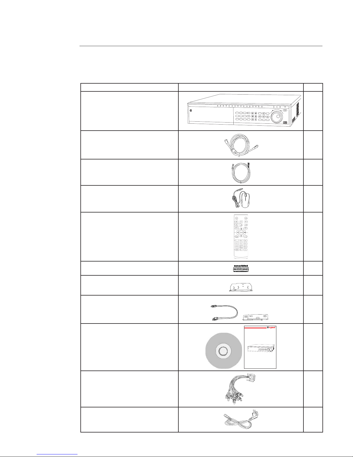
Item description Item picture Qty
DVR
Enter
Mult
Rec
Esc
Fn
1 . ,
2ABC
3DEF
4GHI
5JKL
6MNO
7PQRS
8STU
9WXYZ
-/_
0
1
2
3
4
56
7
89
10
11 12
13
14
15
16
ACT
Status
PWR
Digital Video Recorder
1
HDMI 1
Ethernet 1
Mouse
Remote control
Input / output cables 4
Rack units + screws 2
HDD accessories / HDD power cable
Quick start guide and CD
USER MANUAL
LE04465AA
•Enregistreur LAN HR 4 / 8 / 16 cameras
430 557 / 558 / 559
Enter
Mult
Rec
Esc
Fn
1 . ,
2ABC
3DEF
4GHI
5JKL
6MNO
7PQRS
8STU
9WXYZ
-/_
0
1
2
3
4
56
7
89
10
11 12
13
14
15
16
ACT
Status
PWR
Digital Video Recorder
1
Audio connector
(Not included in the 4 channels DVR)
1
Power cord 1
1. Packing detail
Page 5
5
2. Overview and controls
This section provides information about front panel and rear panel. When you install the DVR, refer to this part rst.
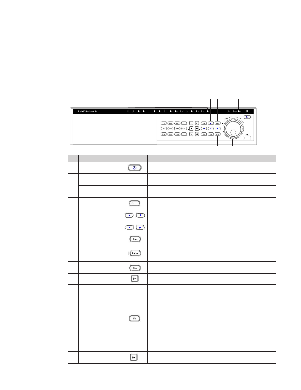
2.1 Front Panel
Front panel buttons information:
Name Icon Function
1 Power button
Power button, press this button for three seconds to boot up or shut
down DVR.
2
Number buttons
0 to 9
0 - 9 Camera select / numeric button.
Input number more
than 10
- / --
If you want to input a number more than 10, click on this button and you
can input more than one number.
3 Shift
In textbox, click on this button to switch between number, small letter,
capital letter and special character. Enable or disable tour.
4 Up / Down
Activate current control, modify setup, and then move up and down. Increase / decrease numeral. Assistant function such as PTZ menu.
5
Left / Right
Shift current activated control, and then move left and right.
When playback, click these buttons to control playback bar.
6 ESC
Go to previous menu, or cancel current operation.
When playback, press to restore real-time monitor mode.
7 Enter
Conrm current operation.
Go to default button.
Go to menu.
8 Record
Manually stop / start recording, working with direction keys or numeral
keys to select the recording channel.
9 Slow play
Multiple slow play speeds or normal playback.
10 Auxilary button
One-window monitor mode, click on this button to display assistant
function: PTZ control and image color.
Backspace function: in numeral control or text control, press it for
1.5 seconds to delete the previous character before the cursor.
In motion detection setup, working with Fn and direction keys to realize
setup.
In text mode, click on it to switch between number, small letter, capital
letter and special character.
In HDD management interface, you can click on it to switch HDD record
information and other information (Menu prompt)
Realize other special functions.
11 Fast Play
Various fast speeds and normal playback.
1
H
J
I
G
8
A
E
C
F
M
L
K
7
4
6
5
B
9
3
N
2
D
Page 6

6
Name Icon Function
12 Play previous
In playback mode, playback the previous video.
13 Reverse / Pause
In normal playback or pause mode, click on this button to reverse
Playback.
In reverse playback, click this button to pause playback.
14 Play Next
In playback mode, playback the next video.
In menu setup, go to down ward of the dropdown list.
15 Play / Pause
In normal playback click on this button to pause playback.
In pause mode, click on this button to resume playback.
16 Window switch
Click on it to switch one-window / multiple-window.
1718Shuttle(outer ring)
Jog(inner dial)
In real-time monitor mode it works as left / right direction key.
Playback mode, counter clockwise to forward and clock wise to backward.
Up / down direction key.
Playback mode, turn the inner dial to realized frame by frame playback.
(Only applies to some special versions.)
19 USB port
To connect USB storage device, USB mouse.
20
Remote control
indication light
ACT Light on the DVR can receive the IR signal from the remote control.
21 Status indication light STATUS If there is “Fn” indication light, current status indication light is null.
22 Power indication light PWR Power indication light.
23 Record light 1 - 16 Incates which channel is recording.
Page 7
7
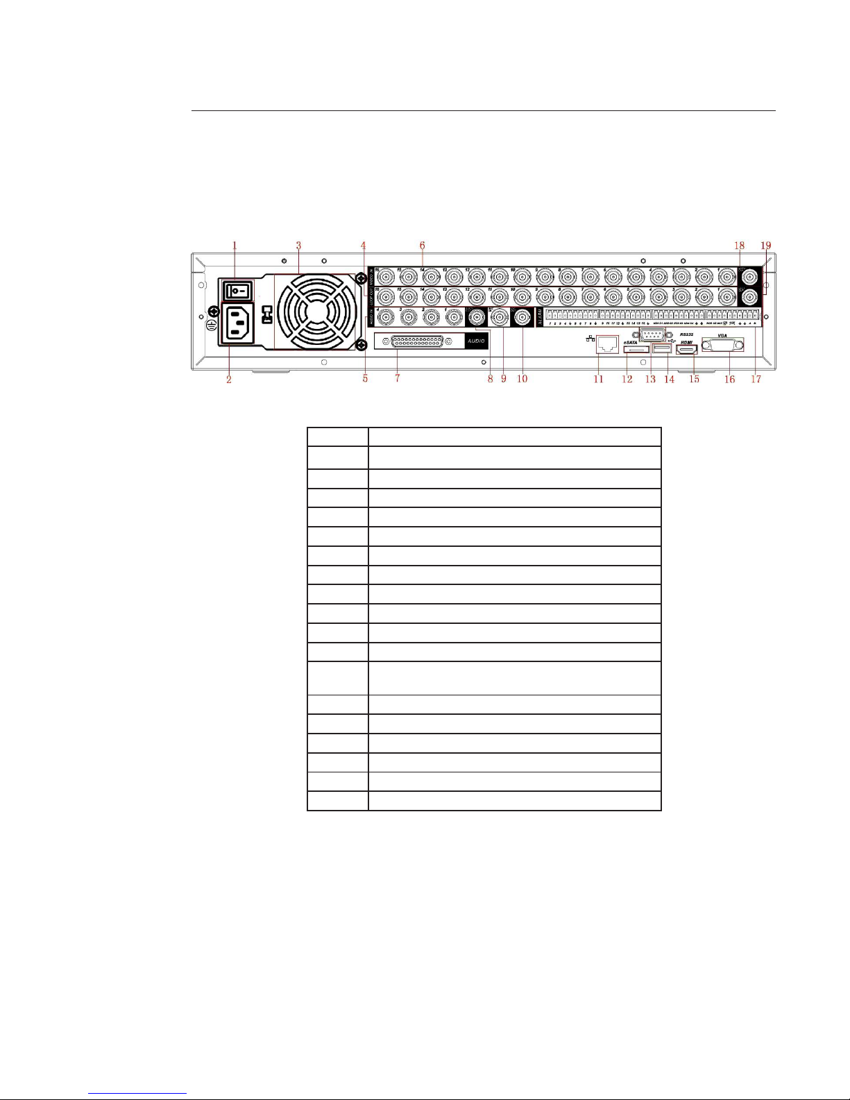
2.2 Rear Panel
Rear panel is shown below.
Rear panel information:
1 Main power switch.
2 Power supply.
3 Fan.
4 Loop video output.
5 1st to 4th-channel audio input.
6 Video input. BNC input port for cameras (4 / 8 / 16).
7 DB25 port (5th to 16th-channel audio input port).
8 Audio output.
9 Bidirectional talk input port.
10 Bidirectional talk output port.
11 Network port.
12 eSATA port for external hard drive.
13 RS232 port. It is for general COM debug to congure IP
adress or transfer transparent COM data.
14 USB port to connect USB key or mousse.
15 HDMI port for HDMI monitor.
16 Video VGA output port for VGA monitor.
17 Alarm input / alarm output / RS485 port, PTZ device.
18 Video CVBS output.
19 Video matrix output.
When you connect the Ethernet port, use crossover cable to connect the PC and use the straight cable to connect to the
switcher or router.
Page 8
8
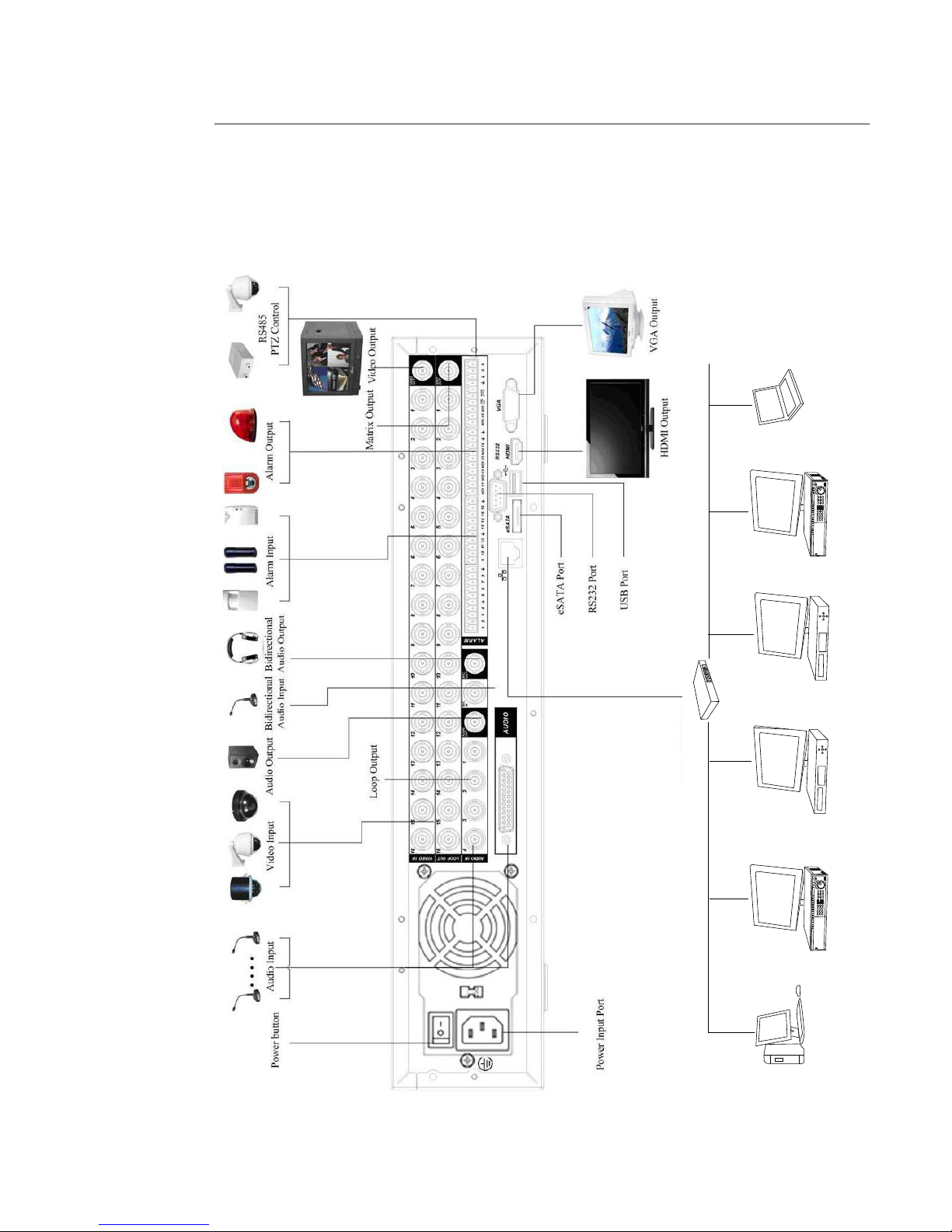
2.3 Connection Sample
Refer to the scheme below for connection sample.
1
2
4
5
7
8
9
A
B
C
D
E
F
H
H
I
J
G
DVR
NVR
NVR
DVR
Net work User
Net work User
Network Switcher
Page 9

99
2.4 Remote control
Name Icon Function
1 Address
When you have several DVR, input the device number you have set
in MAIN MENU -> SETTING -> GENERAL, eld “DVR N°”, so you can
control it.
2 Multiple-window switch Switch between one-window and multiple-window.
3
0-9 number key
Input password, channel or switch channel.
Shift is the button to switch the input method.
In textbox, click this button to switch between number, small,
letter, capital letter and special character.
Open / close tour.
4 Record
Enable or disable record function manually. In record control menu,
working with direction keys to select record channel.
5 Auxiliary key
In 1-ch monitor mode: pop up assistant function: PTZ control and
Video color.
6 Conrm / menu key
Conrm current operation.
Go to the default button.
Go to the menu.
7 Cancel
Go back to the previous menu or cancel current function menu
(Close the upper interface or control.)
In playback mode, play the previous le.
2
3
4
5
6
7
8
9
A
B
1
E
C
D
Page 10

10
Name Icon Fonction
8
,
Up / down
Activate current control, modify setup. Increase / decrease number.
Assistant function such as PTZ menu.
,
Left / right
Shift current activated control.
When playback, click these buttons to control playback bar.
9 Forward Various forward speeds and normal speed playback.
10 Previous Please refer to the previous in the front panel.
11 Backward Various backward speeds and normal speed playback.
12 Next In playback mode, playback the next video
13 Slow play Multiple slow play speeds or normal playback
14 Play / Pause
Reverse playback or paused mode, click this button to realize normal
playback.
In normal playback click this button to pause playback.
In pause mode, click this button to resume playback.
In real-time monitor mode, click this button to enter video search
menu.
Page 11
11
2.5 Mouse operation
Please refer to the following sheet for mouse operation instruction.
Left click
mouse:
System pops up password input dialogue box if you have not logged in.
In real-time monitor mode, you can go to the main menu.
When you have selected one menu item, left click on the mouse to view menu content.
Implement the control operation.
Modify checkbox or motion detection status.
Click on combo box to pop up drop down list.
In input box, you can select input methods.
Left click on the corresponding button on the panel you can input numeral, small letter, capital letter
and special characters.
Double left
click mouse:
Implement special control operation such as double click on an item in the le list to playback the
video. In multiple-window mode, double left click one channel to view in full-window.
Double left click current video again to go back to previous multiple-window mode.
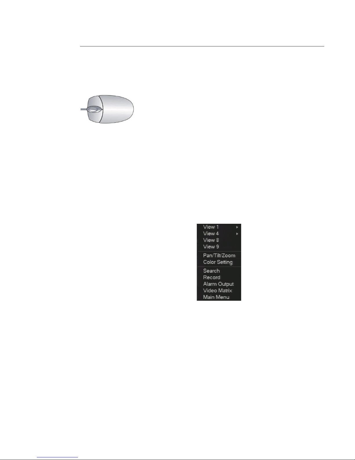
Right click
mouse:
In real-time monitor mode, pops up shortcut menu:
In play back mode, returns to previous windows or previous menu.
Press middle
button:
In numerical input box: Increase or decrease numeral value. Switch the items in the check box. Page
up or page down.
Drag mouse: Select motion detection zone.
Select privacy mask zone.
Page 12

12
2.6 Front Panel
Click “Fn” key and use direction keys to select number you want.
Click on “Enter” button to valid.
Use > or < to shift between small letter and capital letter.
Page 13

13
3 Installation and Connections
Note: All the installation and operations here should conform to your local electric safety rules.
3.1 HDD Installation
The DVR is provided with a SATA HDD and it can be equipped with maximum 8 SATA HDDs.
Recommended models are:
- SEAGATE Barracuda series
- SEAGATE SV35 series
- WESTERN DIGITAL Caviar series.
Follow the instructions below to install hard disk.
1. Loosen the screws of the upper cover
2. Remove the HDD upper bracket 3. Now you can see the bottom
bracket
4. Line up the HDD to the four holes of
the HDD bracket
5. Use four screws to x HDD 6. Install the upper bracket and then
use screws to x HDD in the bracket
7. Unfasten the HDD power cable 8. Insert the HDD power cable 9. Use the special data cable to
connect the HDD and the SATA port.
Close the chassis and x the screws to
secure rmly.
3.2 Rack Installation
The DVR occupies 2 rack units of vertical rack space.
• Use twelve screws to x the unit.
• Please make sure the indoor temperature is below 35°C (95°f).
• Please make sure there is 15cm (6 inches) space around the device to guarantee sound ventilation.
• Please install from the bottom to the top.
• If there are more accessories connected in the rack, please take precaution measures in case the rack power is over-
load.
Page 14
14
3.3 Connecting Power Supply
Please check input voltage and device power button match or not.
We recommend you use UPS to guarantee steady operation, DVR life span, and other peripheral equipments operation
such as cameras.
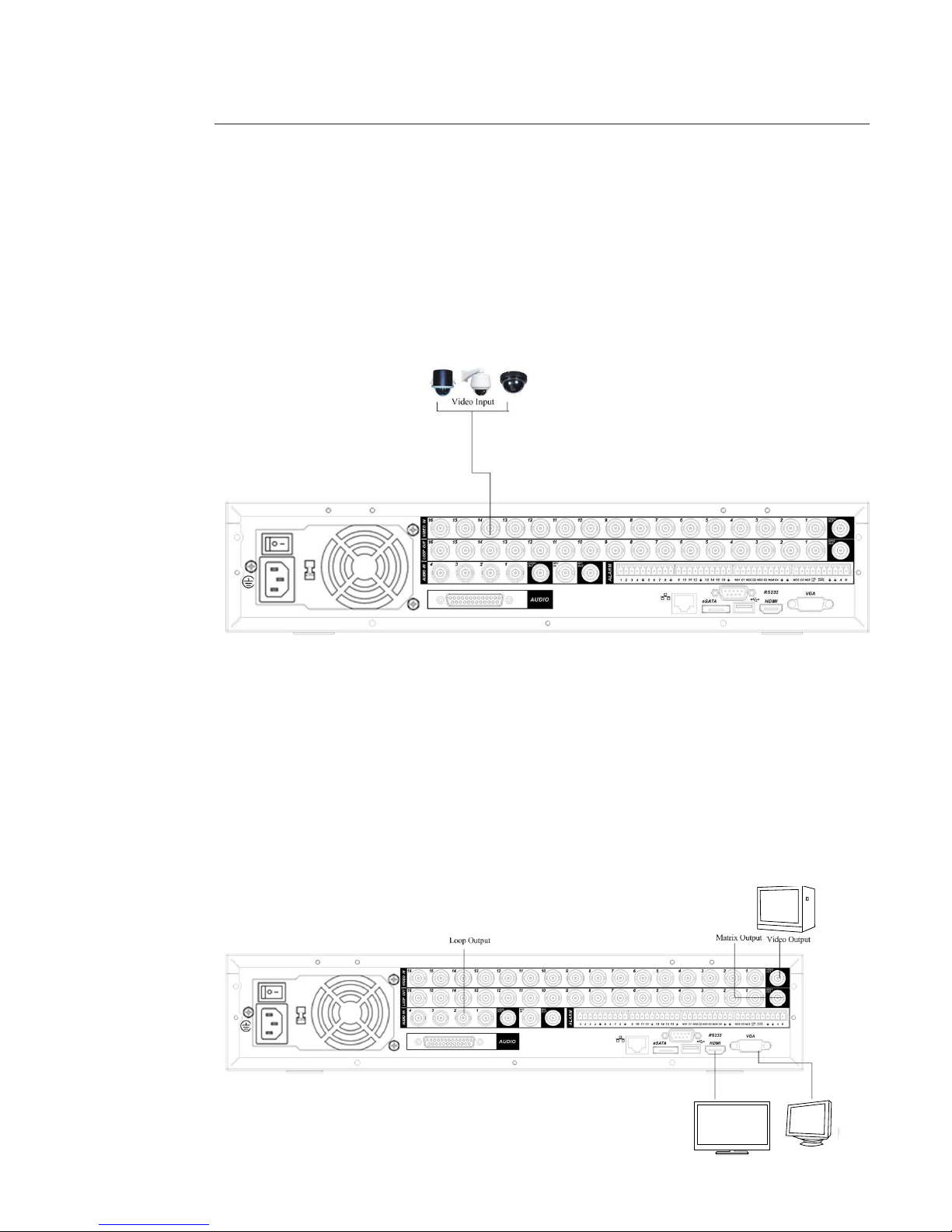
3.4 Connecting Video Input and Output Devices
Connecting Video Input
The video input interface is BNC. The input video format includes: PAL BNC (1.0V.p-p, 75 Ω)
Preferably use VGA or HDMI connections for better image quality.
Connecting Video Output
Video output includes BNC (1.0V.p-p, 75 Ω) output, VGA output and HDMI output.
System supports BNC, VGA and HDMI output at the same time.
When you are using pc-type monitor to replace the monitor, please pay attention to the following points:
• To defer aging, do not allow the pc monitor to run for a long time.
• Regular demagnetization will keep device maintain proper status.
• Keep it away from strong electromagnetic interference devices.
Using TV as video output device is not a reliable substitution method. You also need to reduce the working hour and
control the interference from power supply and other devices. The low quality TV may result in device damage.
HDMI Output
VGA Output
Page 15
15
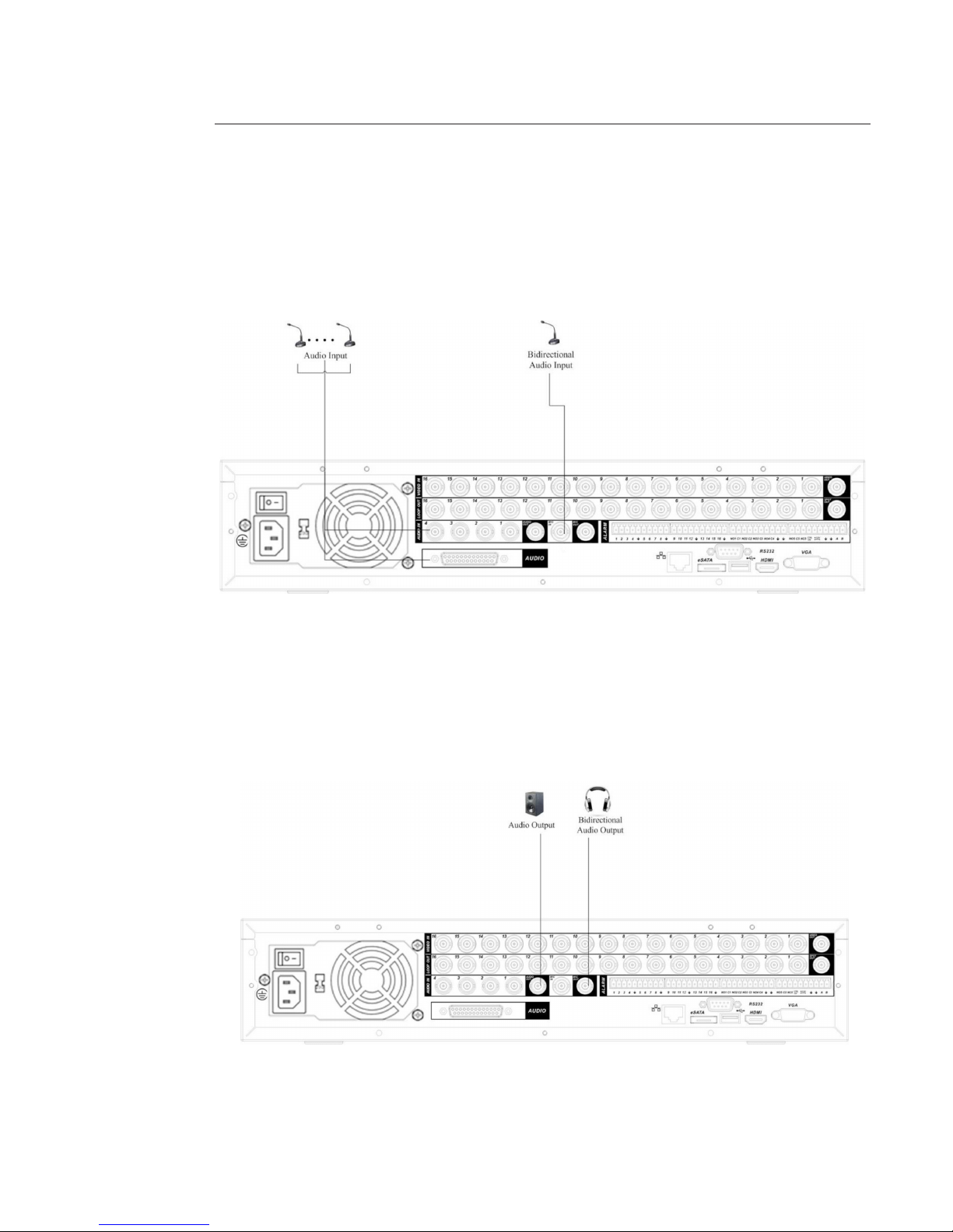
3.5 Connecting Audio Input & Output, Bidirectional Audio
Audio Input
The DVR audio inputs adopt BNC port. Device supports bidirectional talk via BNC.
Due to high impedance of audio input, use active sound pick-up. Audio transmission is similar to video transmission. Try
to avoid interference, dry joint, loose contact and it shall be away from high tension current.
Audio Output
The audio output signal parameter is usually over 200mv 1KΩ (BNC). It can be directly connected to low impedance
earphone, active sound box or amplier-drive audio output device. If the sound box and the pick-up cannot be separated
spatially, it is easy to arouse squeaking. In this case you can adopt the following measures:
• Use better sound pick-up with better directing property.
• Reduce the volume of the sound box.
• Using more sound-absorbing materials in decoration can reduce voice echo and improve acoustics environment.
• Adjust the layout to reduce happening of the squeaking.
Page 16
16
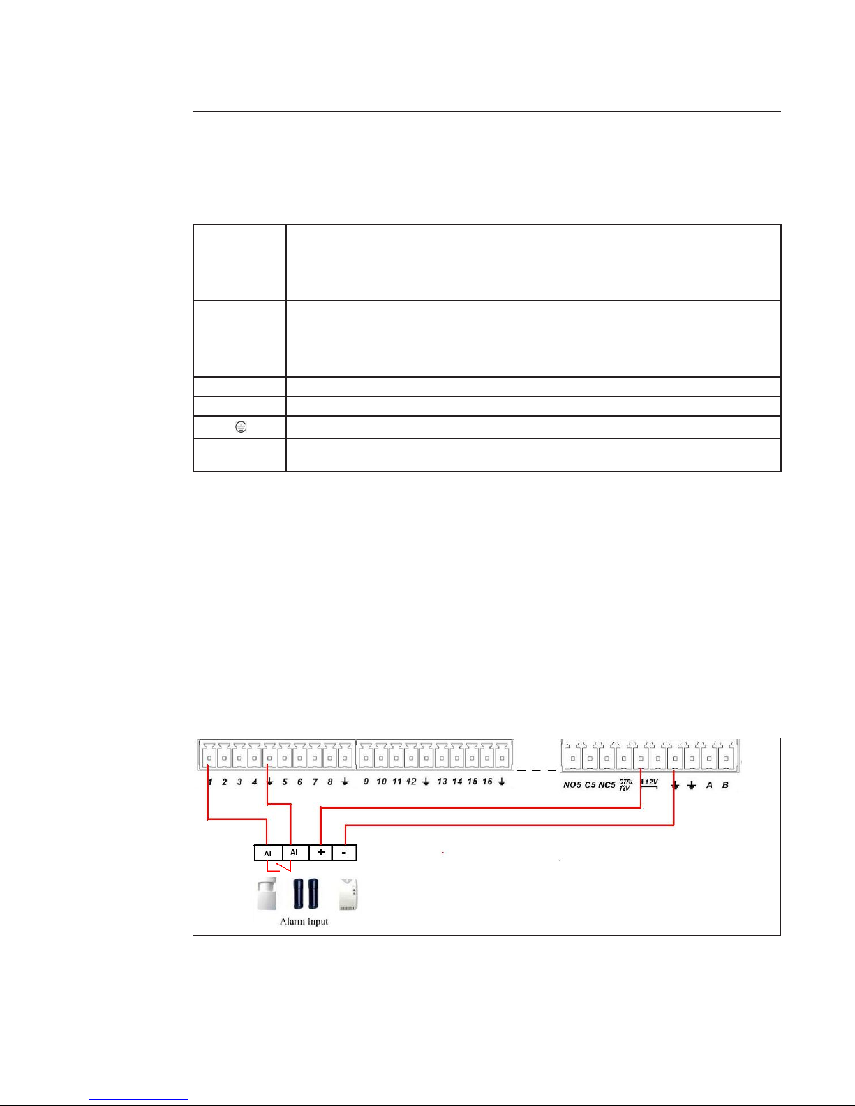
3.6 Alarm Input and Output Connection
Refer to the following sheet for alarm input and output connection.
You can select two alarm input types: Normal Open (NO) and Normal Close (NC).
1. Alarm input
a. Make sure alarm input mode is grounding alarm input.
b. Grounding signal is needed for alarm input.
c. Alarm input needs the low level voltage signal.
d. Alarm input mode can be either NO (Normal Open) or NC (Normal Close).
e. When you are connecting two DVRs or you are connecting one DVR and one other device, use a relay to
separate them.
2. Alarm output
The alarm output port should not be connected to high power load directly (It shall be less than 1A) to avoid high
current which may result in relay damage. Use the contactor to realize the connection between the alarm output port
and the load.
3. How to connect PTZ decoder
a. Ensure the decoder has the same grounding with DVR, otherwise you may not control the PTZ. Shielded
twisted wire is recommended and the shielded layer is used to connect to the grounding.
b. Avoid high voltage. Ensure proper wiring and some thunder protection measures.
c. For too long signal wires, 120Ω should be parallel connected between A, B lines on the far end to reduce
reection and guarantee the signal quality.
d. RS 485 A, B of DVR cannot parallel connect with “RS485 port” of other device.
e. The voltage between of A, B lines of the decoder should be less than 5v.
4. Please make sure the front-end device is linked to ground
Improper grounding may result in product damage.
+ -
Page 17
17
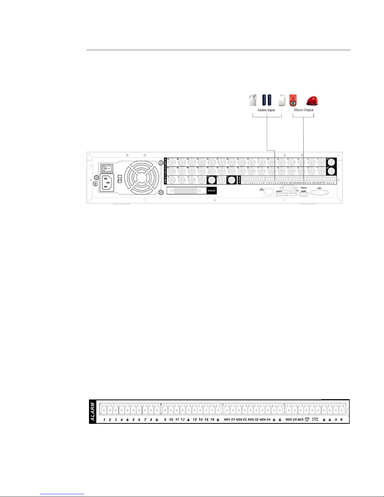
Alarm Input and Output Details
You can refer to the following sheet for input and output alarm information.
From the left to
the right,: 1, 2, 3,
4, 5, 6, 7, 8, 9,10,
11, 12, 13, 14, 15,
16
Alarm input 1 to Alarm input 16. The alarm becomes active in low voltage.
NO1 C1,
NO2 C2,
NO3 C3,
NO4 C4,
NO5 C5 NC5
Alarm output.
The rst four are four groups of Normal Open activation output (“on / o ” button).
For example, connect NO1 to earth.
NO5 C5 NC5 is a group of NO / NC activation output (“on / o” button).
CTRL 12V Control power output. You need to close the device power to cancel the alarm.
+12V It is external power input. Need the peripheral equipment to provide +12V power (below 1A).
Ground cable.
RS485 A, B RS 485 communication port. They are used to control devices such as PTZ. Please parallel connect
120Ω between A+ / B- cables if there are too many PTZ decoders.
Alarm Input Port
Please refer to the following sheet for more information.
• 4 / 8 / 16-ch grounding alarm inputs. (Normal Open or Normal Close type).
• Parallel connect COM end and GND end of the alarm detector (Provide external power to the alarm detector).
• Parallel connect the Ground of the DVR and the ground of the alarm detector.
• Connect the NC port of the alarm sensor to the DVR alarm input (ALARM).
• Use the same ground with that of DVR if you use external power to the alarm device.
• Use the controllable +12V power to reset the smoke sensor remotely.
Example 1: Input alarm connection.
The end device is Normally Open (NO) or Normally Close (NC) and the DVR can be set in MAIN MENU->SETTING->ALARM.
If the end device is NO the alarm setting in the DVR is NO.
If the end device is NC the alarm setting in the DVR is NC.
Page 18
18
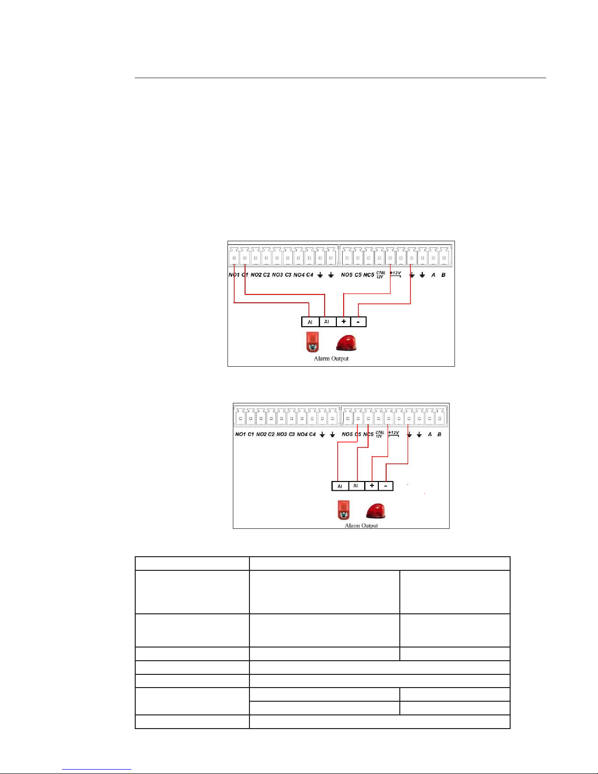
Alarm Output Port
• Provide power to peripheral alarm device.
• To avoid overloading, please read the following relay parameters sheet carefully.
• Controllable +12V, can be used to provide power to devices such as reset smoke sensor.
• RS485 A / B cable is for the A / B cable of the decoder PTZ.
Cabling gives the alarm status NO or NC. The alarms are controlled by “Manual”, “Schedule” and “Stop” actions in the MAIN
MENU->ADVANCED->ALARM OUTPUT.
Example 2: Alarm output NO (Normally Open) connection. N01 C1, N02 C2, N03 C3, N04 C4 and N05 C5.
In this case, the “Stop” action opens the circuit (ex:the light is o ) and the “Manual” action closes the circuit.
Example 3: Alarm output NC connection NC5 C5.
In this case, the “Stop” action closes the circuit (ex:the light is on) and the “Manual” action opens circuit.
Relay Specication
Material of the touch Silver
Rating (Resistance Load) Rated switch capacity
Maximum switch power
Maximum switch voltage
Maximum switch currency
30VDC 2A, 125VAC 1A
125VA 160W
250VAC, 220VDC
1A
Insulation Between touches with same polarity
Between touches with dierent polarity
Between touch and winding
1000VAC 1minute
1000VAC 1minute
1000VAC 1minute
Surge voltage Between touches with same polarity 1500V (10×160us)
Length of open time 3ms max
Length of close time 3ms max
Longevity Mechanical 50×106 times (3Hz)
Electrical 200×103 times (0.5Hz)
Temperature -40°C ~+70°C
Page 19

19
3.7 RS232
You can connect the DVR with POS or Keyboard through RS232.
With POS system, the DVR can communicate through RS232 and the network.
The DVR can also integrate text content and even search the record based on the text.
Please contact the technical support to implement this function.
3.8 RS485
When the DVR receives a camera control command, it transmits that command up the cable to the PTZ device. RS485
is a single-direction protocol; the PTZ device can’t return any data to the unit. To enable the operation, connect the PTZ
device to the RS485 (A,B) input on the DVR.
Since RS485 is disabled by default for each camera, you must enable the PTZ settings rst. This series DVRs support
multiple protocols such as Pelco-D, Pelco-P.
To connect PTZ devices to the DVR:
1. Connect RS485 A+ / B- on the DVR rear panel.
2. Connect the other end of the cable to the proper pins in the connector on the camera.
3. Please follow the instructions to congure a camera to enable each PTZ device on the DVR.
Page 20
20
4 Graphic User Interface Operations
Connect the device to the monitor and to the cameras, insert the mouse and connect the power cable. Push the on / o
button in the rear panel and then you can see the analog video output. You can use the mouse to implement some simple
GUI operation. Refer to the following chapter for detail information.
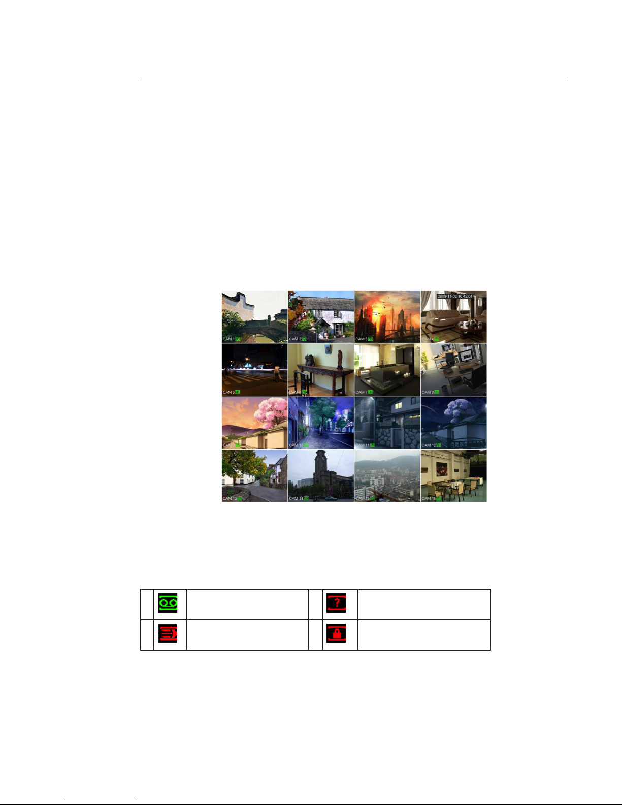
4.1 In live view
After device booted up, the system is in multiple-channel display mode.
You can see system date, time and channel name. If you want to change system date and time, you can refer to general
settings (MAIN MENU -> SETTING -> GENERAL). If you want to modify the channel name, please refer to the display settings (MAIN MENU -> SETTING -> DISPLAY). For detailed operations, see paragraphe 5.5.
The wizard is launched and prompts the user to congure the main menus (“General”, “TV adjust”, “Encode”, “Schedule”,
“Record”, “Control” and “Network”).
Channel display
To display channels and switch between dierent windows, you can use:
- Right click mouse and choose “view 1”, “view 4”, “view 8” or “view 9”
- “Mult” button, on remote control or on front panel.
Information Screen
1 Recording status 3 Video loss
2 Motion detection 4 Camera lock
Page 21
21
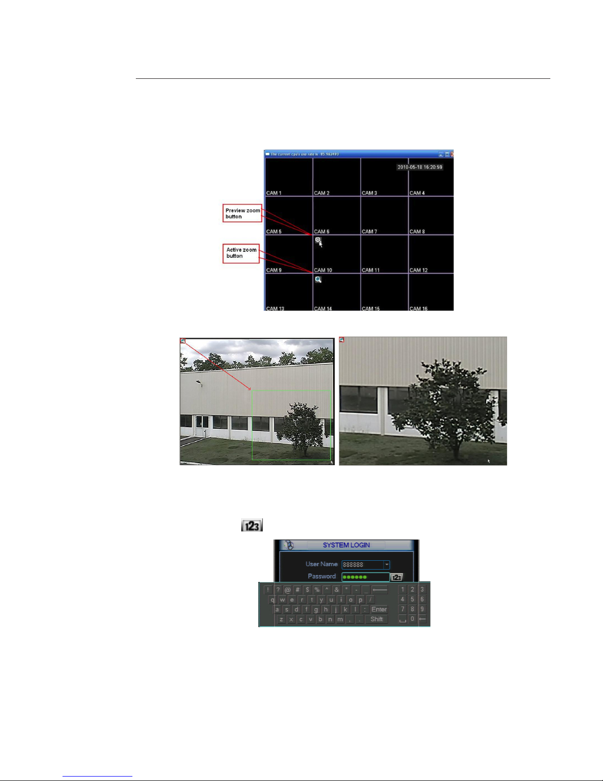
Preview Zoom Function:
Move your mouse to the left top corner of the preview interface; you can see the preview zoom button. You see a hook
icon on the picture below, left click on this one. Now you have enabled the preview zoom function.
You can drag the mouse to zoom in the image.
4.2 Login
After system booted up, default video display is in multiple-window mode.
Click Enter or left click mouse, you can see the login interface. Input user name and password.
You can use USB mouse, front panel, remote control or keyboard to input.
About input method: Click on to switch between number, small and capital letter and special character.
Factory setting consists of four accounts:
• Username: 888888 Password: 888888 (administrator, local only)
• Username: admin Password: admin (administrator, local and network)
• Username: 666666 Password: 666666
(Lower authority user who can only monitor, playback, backup and etc.)
• Username: default password: default (hidden user).
Note:
For security reason, please modify the password after your rst login.
Within 30 minutes, three times login failure will result in system alarm and ve times login failure will result in account
lock!
Page 22
22
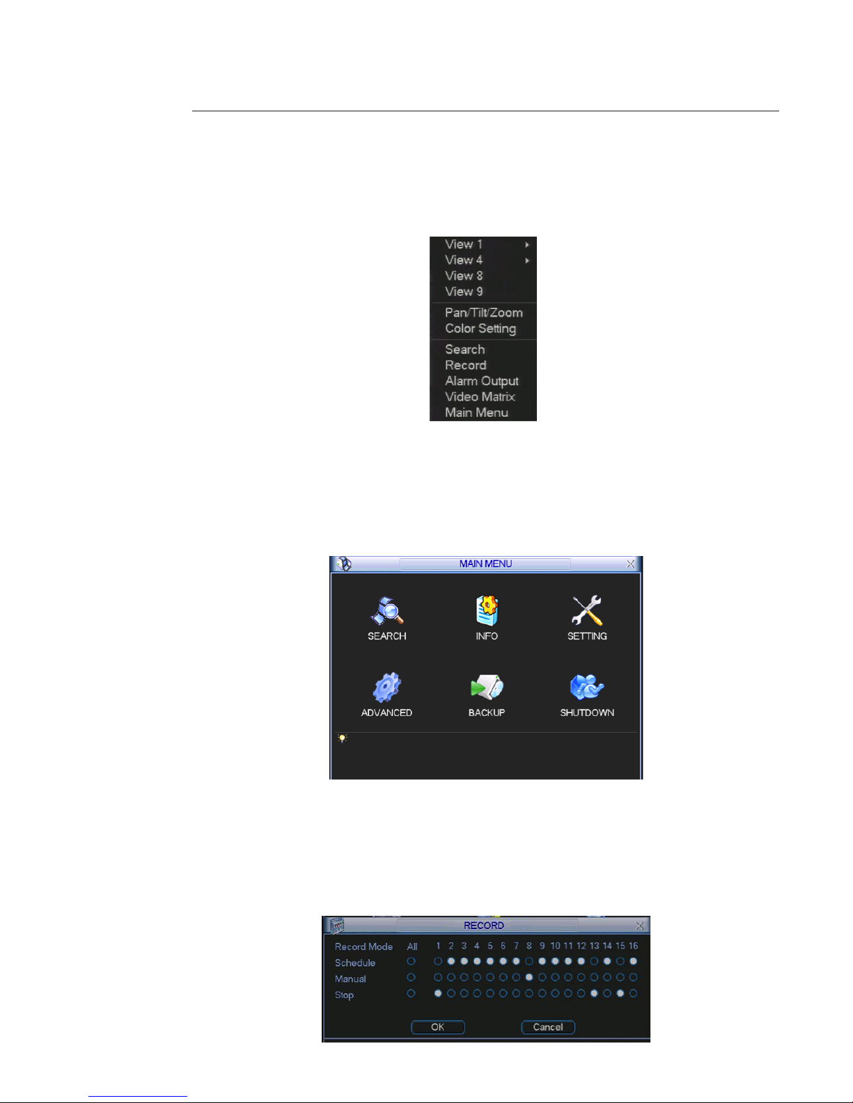
4.3 Right Click Menu
After you logged in the device, a right click mouse, display the short cut menu.
You can set windows display, PTZ control, video color, search record etc. The live view window includes 1 / 4 / 9 / 16.
Important :
Before starting record or setting action, set the language, the date and time system in MAIN MENU -> SETTING ->
GENERAL. Set System time / hour system / language.
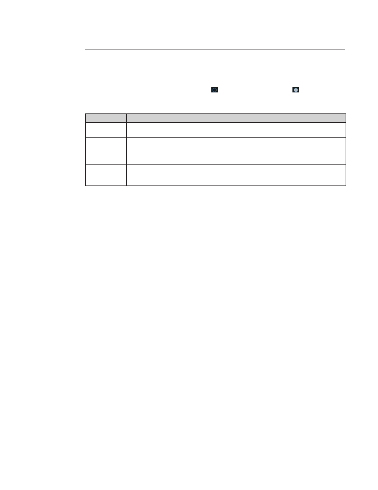
4.4 Main Menu
Left click mouse or select “Main Menu” in short cut menu, there are six icons; “SEARCH”, “INFO”, “SETTING”, “ADVANCED”,
“BACKUP” and “SHUTDOWN”. Move the cursor to highlight the icon, then left click mouse to open the sub-menu.
Right click mouse returns to previous windows or previous menu.
For detailed operations, see paragraphe 5.2.
4.5 Manual record
You need to have proper rights to implement the following operations.
There are several ways to activate manual record:
• The shortcut menu, right click mouse on the screen and select “Record” in the list.
• The long menu, go to the MAIN MENU -> ADVANCED -> RECORD.
• Press “Record” button in the front panel or “Record” button of the remote control.
Page 23
23
Manual record operations
Use mouse or direction key to highlight a channel number, means it is not in recording status, means is in recording
status.
There are three statuses: Schedule / Manual / Stop.
Statuses Functions
Schedule Channel will record as you have previously set in MAIN MENU -> SETTING -> SCHEDULE.
All channel Schedule record: highlight “All” after “Schedule”
Manual The highest priority. After manual setup, all selected channels will begin ordinary recording. When
system is in manual recording, all scheduled set up you have set in the MAIN MENU -> SETTING ->
SCHEDULE will be null.
All channel Manual record: highlight “All” after “Manual.”
Stop All channels stop recording. System stops all channel recording no matter what mode you have set
in the MAIN MENU -> SETTING -> SCHEDULE
Stop all channel recording: highlight “All” after “Stop”.
The record statuses begin after clicking on “OK” button. The corresponding indication light in front panel will turn on or
turn o.
Page 24
24
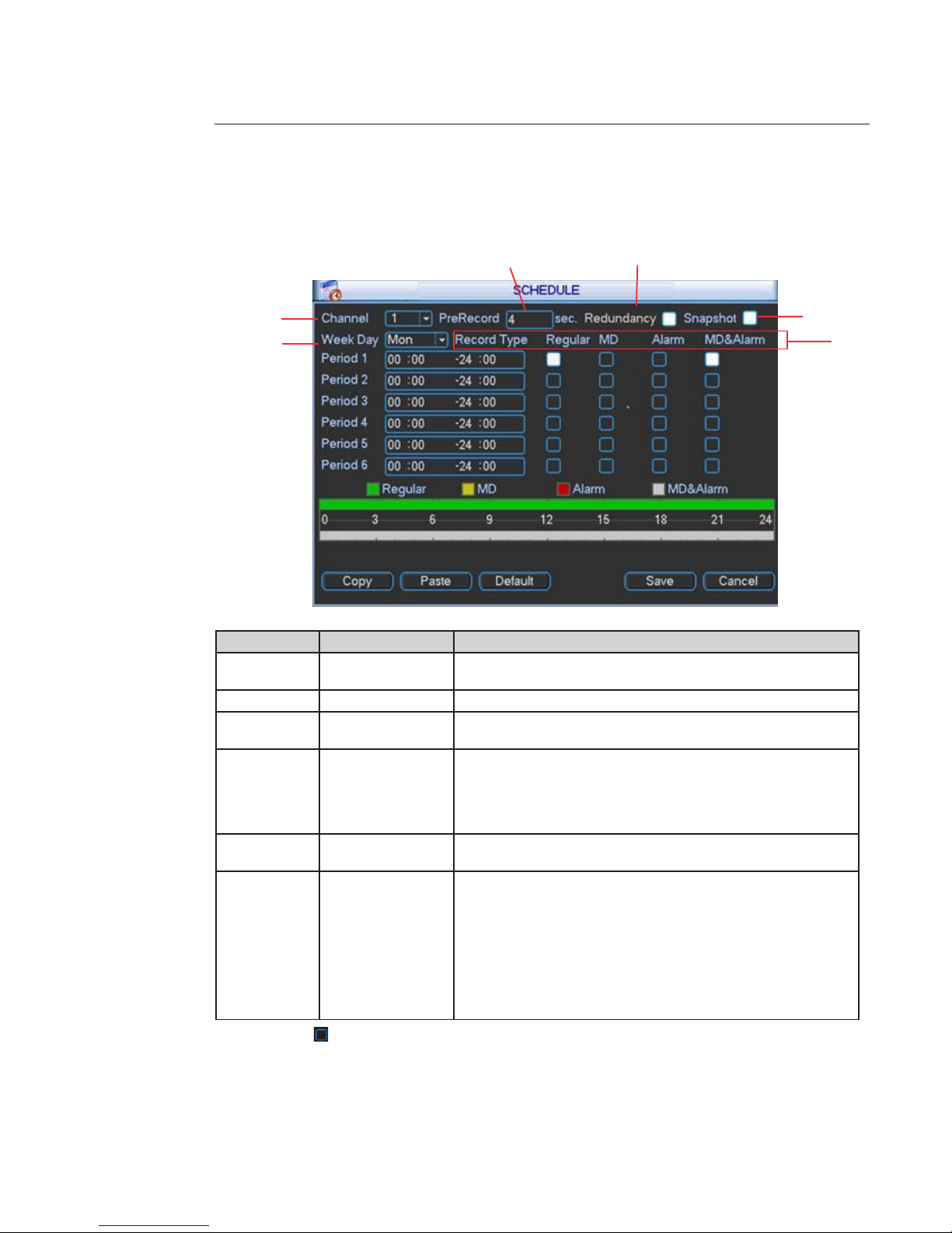
4.6 Schedule
Go to MAIN MENU ->SETTING -> SCHEDULE
The default schedule setting is 24 hours regular mode.
You can dene 6 periods for each week days per channel. If “All” “Week Day” is selected, the periods apply for all the week
days.
Number Item Function
1 Channel
Select the channel number rst. You can select “all” if you want to set for
the whole channels.
2 Week day There are eight options: ranges from Saturday to Sunday and all.
3 Pre-record
system can pre-record the video before the event occurs. The value
ranges from 1 to 30 seconds depending on the bit stream.
4 Redundancy
If there are several HDD discs, system supports redundancy backup
function. It allows you backup recorded le in two disks. You can highlight
“Redundancy” box to activate this function. Before enable this function,
set at least one HDD as redundant in MAIN MENU -> ADVANCED -> HDD
MANAGE. Refer to HDD manage chapter for more detailed information.
5 Snapshot
you can enable this function to take a snapshot when an alarm occurs.
For setting, refer to “Auxiliary Functions” chapter.
6 Record types
there are four types: Regular, Motion Detection (MD), Alarm and MD &
alarm.
At the bottom of the menu, there are color bars for your reference.
The green color stands for regular recording.
The yellow color stands for motion detection and red color stands for
alarm recording.
The white means the MD and Alarm record is setting. Once you have set
to record when the MD and alarm occurs, system won’t record if only
motion detect occurs or if only the alarm occurs.
Highlight the box to select the corresponding function. After completing all the setups click on “Save” button,
the system goes back to the previous menu.
1
2
3 4
5
6
Page 25
2525
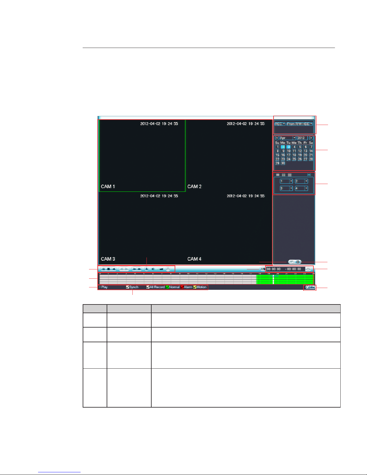
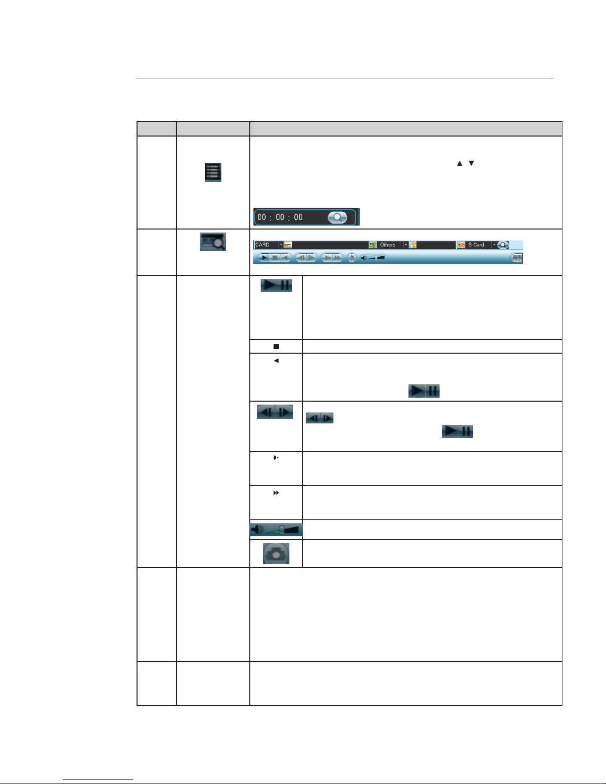
4.7 Research recording and playback
Click search button in the main menu, search interface is shown as below. Usually there are three le types:
- R: Regular recording le.
- A: External alarm recording le.
- M: Motion detection recording le
SN
Name Function
1
Display / window Here is to display the searched picture or le.
Support 1 / 4 / 9 / 16-window playback.
2
Search type Here you can select to search the picture or the recorded le.
When there is displayed picture on the left pane, you can set the corresponding setup.
3
Calendar The blue highlighted date means there is picture or le. Otherwise, there is no picture
or le.
In any play mode, click the date you want to see, you can see the corresponding record
le trace in the time bar.
4
Playback mode
and channel
selection pane
Playback mode 1 / 4 / 9 / 16. (It may vary due to dierent series.)
- In 1-window playback mode: you can select 1-16 channels.
- In 4-window playback mode: you can select 4 channels according to your requirement.
- In 9-window playback mode, you can switch between 1-9 and 10-16 channels.
- In 16-window playback mode, you can switch between1-16 and 17-32 channels.
The time bar will change once you modify the playback mode or the channel option.
2
3
4
56
A
B7
8
C
9
E
D
1
Page 26
26
SN
Name Function
5
File list switch
button
- Double click it, you can view the picture / record le list of current day.
- The le list is to display the rst channel of the record le.
- The system can display max 128 les in one time. Use the / or the mouse to view
the le. Select one item, and then double click the mouse or click the ENTER button to
playback.
- You can input the period in the following interface to begin accurate search.
- File type: R—regular record: A—external alarm record: M—Motion detect record.
6
Card number
search
The card number search interface is shown as below:
7
Playback control
pane
Play / Pause
There are three ways for you to begin playback.
- The play button
- Double click the valid period of the time bar.
- Double click the item in the le list.
In slow play mode, click it to switch between play / pause.
Stop
Backward play
In normal play mode, left click the button, the le begins backward play.
Click it again to pause current play.
In backward play mode, click to restore normal play.
In normal play mode, when you pause current play, you can click
to begin frame by frame playback.
In frame by frame playback mode, click to restore normal
playback.
Slow play.
In playback mode, click it to realize various slow play modes such as
slow play 1, slow play 2, and etc.
Fast forward.
In playback mode, click to realize various fast play modes such as fast
play 1,fast play 2 and etc.
The volume of the playback
Click the snapshot button in the full-screen mode, the system can snapshot 1 picture per second.
8 Time bar
- It is to display the record type and its period in current search criteria.
- In 4-window playback mode, there are corresponding four time bars. In other playback
mode, there is only one time bar.
- Use the mouse to click one point of the color zone in the time bar, system begins
playback.
- The time bar is beginning with 0 o'clock when you are setting the conguration. The
time bar zooms in the period of the current playback time when you are playing the le.
- The green color stands for the regular record le. The red color stands for the external
alarm record le. The yellow stands for the motion detect record le.
9 Time bar unit
The option includes: 24H, 12H, 1H and 30M. The smaller the unit, the larger the zoom
rate. You can accurately set the time in the time bar to playback the record.
The time bar is beginning with 0 o'clock when you are setting the conguration. The
time bar zooms in the period of the current playback time when you are playing the le.
Page 27
2727
SN
Name Function
10 Backup
Select the le(s) you want to backup from the le list. System max supports les from
four channels. Then click the backup button, now you can see the backup menu. Click
the start button to begin the backup operation.
Check the le again you can cancel current selection.
System max supports to display 32 les from one channel.
11 Clip
- It is to edit the le.
- Please play the le you want to edit and then click this button when you want to edit.
You can see the corresponding slide bar in the time bar of the corresponding channel.
You can adjust the slide bar or input the accurate time to set the le end time. Click this
button again and then save current contents in a new le.
12 Record type In any play mode, the time bar will change once you modify the search type.
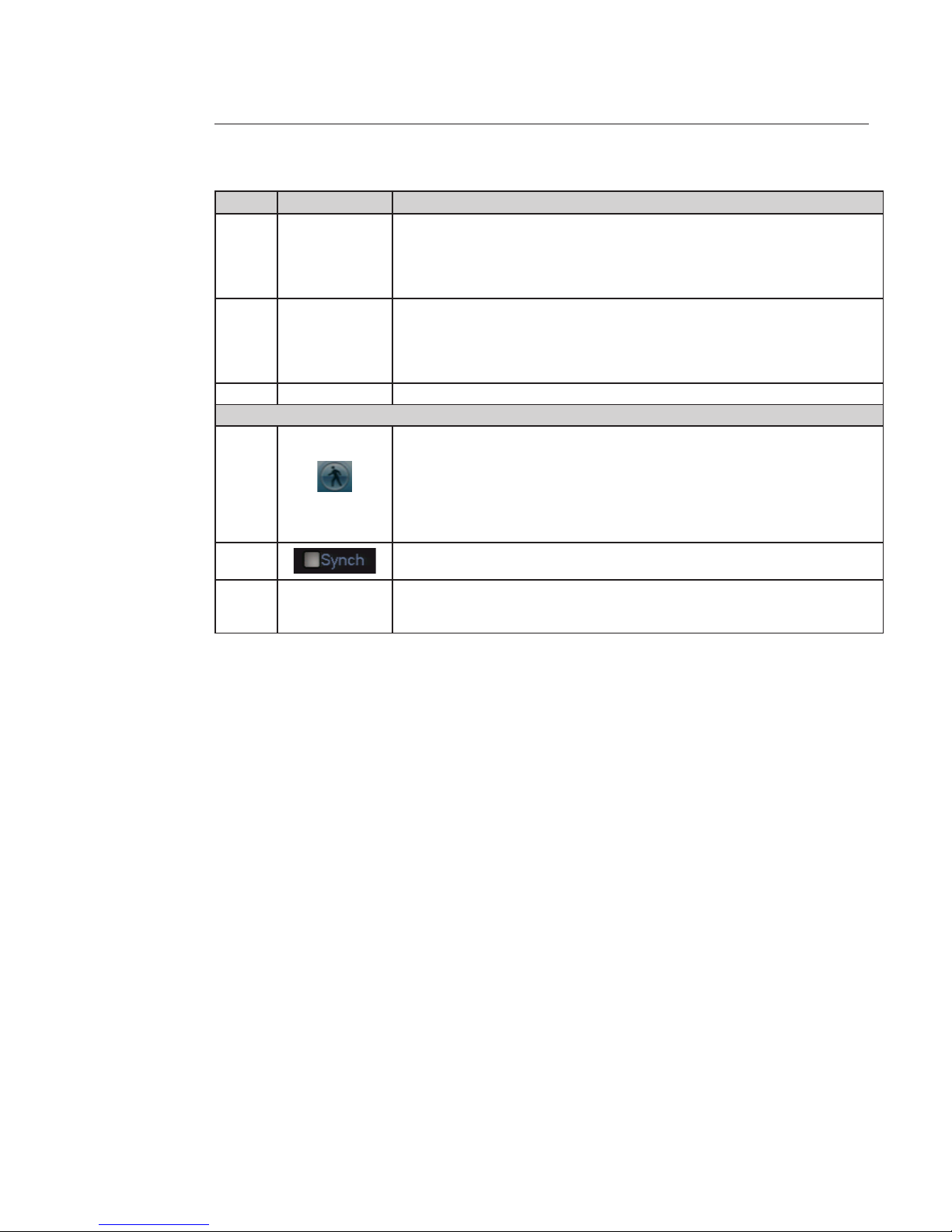
Others functions
13
Smart search
When system is playing, you can select a zone in the window to begin motion detect.
Click the motion detect button to begin play.
Current button is null once the motion detect play has begun.
The system will take the whole play zone as the motion detect region by default.
The motion detect play stopped once you switch the play le.
Operations such as set time bar, click the play button, or any le list operation will stop
current motion detect play.
14
When playing the le, click the number button, system can switch to the same period of
the corresponding channel to play.
15 Digital Zoom
When the system is in full-screen playback mode, left click the mouse in the screen.
Drag your mouse in the screen to select a section and then left click mouse to realize
digital zoom. You can right click mouse to exit.
Page 28
28
Full screen (15)
In full screen mode, the toolbar is hidden, put the cursor on the screen bottom to bring it.
Digital zoom (16)
Drag your mouse in the screen to select a section and then left click mouse to realise digital zoom.
Right click mouse returns to the previous screen.
Page 29
29
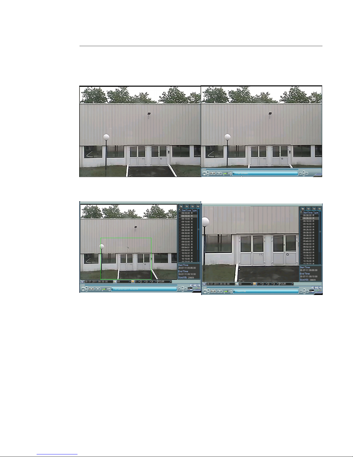
4.8 PTZ
Note: To congure the motorized camera which are in our range you have to congure the DVR. All the operations here
are based on PELCOD protocol and 2400 Bauds. For other protocols, there might be little dierences.
PTZ Setup
Note: The camera video should be in the current screen. Before setup, please check the following connections are right:
• PTZ and decoder connection is right. Decoder address setup is right.
In the MAIN MENU -> SETTING -> PAN / TILT / ZOOM item. The interface is shown below. Here you can set the following
items:
Number Item Function
1 Channel Select the current camera channel.
2 Protocol Select corresponding PTZ protocol such as PELCOD.
3 Address Default address is 1, input corresponding PTZ address.
4 Baud rate
Select corresponding baud rate.
Default value is 9600, input 2400 Bauds
5 Data Bits Select corresponding data bits. Default value is 8.
6 Stop Bits Select corresponding stop bits. Default value is 1.
7 Parity
There are several options: odd / even / none / Mark / Space.
Default setup is none.
After completing all the settings, click on the “Save” button, system goes back to the previous menu.
1
2
3
4
6
7
5
Page 30
30
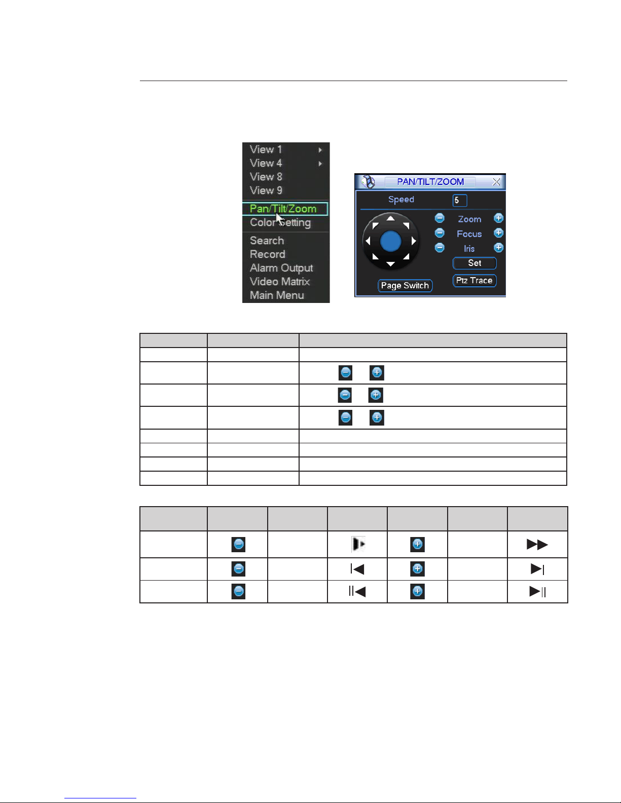
In the short cut menu select “Pan / Tilt / Zoom”, the motorized camera view display and the PTZ control interface appears.
Number Item Function
1 Speed Value ranges from 1 to 8. Set the camera movement speed.
2 Zoom
Click icon and to adjust zoom. (See below for details)
3 Focus
Click icon and to adjust focus if the camera is set in manual focus.
4 Iris
Click icon and to adjust iris if the camera is set in manual iris.
5 Direction arrows Adjust PTZ position. There are 8 direction arrows.
6 Set Manage the preset.
7 Ptz Trace The mouse on the screen can drive the speed dome direction.
8 Page Switch Next page.
Zoom, focus, iris details
Name Key Function
Front pannel
key
Key Function
Front pannel
key
Zoom
Far
Near
Focus
Near
Far
Iris
close
Open
Page 31

31
Preset
Preset Setup
1 - Use eight direction arrows to adjust camera to the proper position.
2 - Click on the “Set” button in the interface below and enter the preset number you want.
3 - The system saves the speed dome position and the preset number when you click on the “Set” button.
You can set the following items:
• Preset : Max 127 positions can be stored as “Preset” position.
The “Preset” number can be assigned from 1 to 128, but 95 is reserved for starting OSD menu.
• Tour => not available
• Pattern => not available
• Border => not available
Activate Preset
Click on the “Page Switch “, you can see the interface below, input preset number in the “No.” blank, and click on the “Preset” button. The speed dome goes to the preset number.
Note:
The “Tour” (Patrol) and the “Pattern” buttons are not available in the auxiliary menu. You can set them using the reserved
Preset through the OSD menu of the speed dome. You need to refer the user’s manual speed dome.
You can dene them as you require.
Page 32

32
To enter in OSD menu, call “Preset 95”. The OSD menu displays.
OSD menu control :
- Use the down and up direction arrows to select parameter.
- Save the value and exit with - focus “near”.
- Modify with the up and down arrow.
- Cancel the value with - focus “far”.
You need to refer to your speed dome user’s manual for “Aux Oper”.
4.9 Remote connections: Interface Web and mobiles applications
Operating system compatibility and navigator for the Web interface
OS Navigator Win XP - Win 7 - Vista Mac os
Internet Explorer 7 – 8 – 9 OK No
Firefox
Google Chrome
Ok with plugin "IE Tab" No
Safari No No
Mobile applications
Platform Iphone
IOS4&5
Ipad
IOS4&5
Android Symbian
(Nokia, Sony /
Ericson)
Android
version 2.x,
3.x, 4.x
Blackberry Win Mobile
Name Apps DMSS (free)
iDMSS (free)
iDMSS-T (free)
DMSS Plus
(not free)
iDMSS
(free)
iDMSSHD (not
free)
General_DMSSSymbian-Direct_Eng_
IS_V1.53.0.R.110311.sis
DMSS (free)
DMSS -Pro
(not free)
gDMSS (free)
gDMSS plus
(not free)
DMSS.alx +
DMSS.cod
General_
DMSS-MobileDirect_Eng_
N5_IS_
V1.22.1.R.
100903.cab
Downloads Appstore Appstore CD Play store CD CD
PTZ operation ok ok No ok No No
Page 33

33
5. Understanding of Menu Operations and Controls
5.1 Menu Tree
SEARCH 4.7
INFO 5.4
________________ HDD INFO 5.4.1
________________ BPS 5.4.2
________________ LOG 5.4.3
________________ VERSION 5.4.4
________________ ONLINE USERS 5.4.5
SETTING 5.5
________________ GENERAL 5.5.1
________________ ENCODE 5.5.2
________________ SCHEDULE 5.5.3
________________ RS232 5.5.4
________________ NETWORK 5.5.5
________________ ALARM 5.5.6
________________ DETECT 5.5.7
________________ PAN / TILT / ZOOM 4.8
________________ DISPLAY 5.5.9
________________ DEFAULT 5.5.10
ADVANCED 5.6
________________ HDD MANAGE 5.6.1
________________ ABNORMALITY 5.6.2
________________ ALARM OUTPUT 5.6.3
________________ RECORD 4.5
________________ ACCOUNT 5.6.5
________________ AUTO MAINTAIN 5.6.6
________________ TV ADJUST 5.6.7
________________ VIDEO MATRIX 5.6.8
________________ TEXT OVERLAY 5.6.9
________________ CONFIG BACKUP 5.6.10
BACKUP 5.7
SHUTDOWN 5.8
5.2 Main Menu
After you logged in, the system main menu is shown below. There are six icons: SEARCH, INFO, SETTING, ADVANCED,
BACKUP and SHUTDOWN. Move the cursor to highlight the icon, then click mouse to open the sub-menu.
5.3 Search
Refer to the “Search Records and Playback” chapter (4.7).
MAIN
MENU
5.2
Page 34

34
5.4 Info
Here is for you to view system information. There are total ve items: HDD INFO (hard disk information), BPS (data stream
statistics), LOG, VERSION, and ONLINE USERS.`
5.4.1 HDD Info
Here is to list hard disk type, total space, free space, video start time and status.
0 means current HDD is normal
X means there is error
- means there is no HDD
“?” means the disk is damaged
When HDD conict occurs, you can check the system time and the HDD time are identical. If they are not identical, Go to
GENERAL menu (MAIN MENU -> SETTING -> GENERAL) to adjust system time or go to HDD MANAGE menu (MAIN MENU
-> ADVANCED ->HDD MANAGE) to format HDD and then reboot the DVR.
After system booted up, if there is any conict, system goes to HDD information interface directly.
Page 35

35
5.4.2 BPS
You can see current video data stream in Kilo Bytes per second (KB / s) and occupied hard disk storage in Mega Bytes per
hour (MB / h).
5.4.3 LOG
You can see the system log le. The log le contents 1024 lines and it lists the following information.
The log types include system operation, conguration operation, data management, alarm event, record operation, log
clear and etc.
Select a start time and an end time then, click on the “Search” button. You can see the log les, if there are more than ten
le use the “Page Up / Down” button.
System also supports the backup function; you can click on the “Backup” button to save the log les in the USB devices.
When you select an event on the log list, you can see the detailed information of this event clicking or “Detail button”. The
following window is displayed.
Page 36

36
5.4.4 VERSION
Here you can view some version information and upgrade the system.
• Channels
• Alarm in
• Alarm out
• System version:
• Build Date
• Web
• Serial No
USB Upgrade instructions
1) Rename the rmware le to “update.bin”.
e.g.: rename “General_DVR0804LB-U_Eng_P_V2.602.0000.1.20080723.bin” to “update.bin”.
2) Insert the USB key into your computer. Copy the “update.bin” le into your USB ash drive.
Warning : please put it in the outmost layer of the USB ash do not put it in any sub folder.
3) Insert the USB key into DVR.
4) Click on “Start” it will start USB upgrade.
Don’t shut down the power during the process.
Page 37

37
5.4.5 ONLINE USERS
Here you can manage online users.
You can disconnect one user or block one user if you have proper system right. Max disconnection setup is 65535
seconds
5.5 Setting
MAIN MENU -> SETTING interface is shown below.
Page 38

38
5.5.1 General
1 - System time: Here is for you to set system time
2 - Date format: There are three types: YYYYY-MM-DD: MM-DD-YYYYY or DD-MM-YYYY.
3 - Date separator: There are three denotations to separate date: dot, beeline and solidus.
4 - DST: Here you can set DST time and date.
(Daylight saving time) Please enable DST function and then click on the “Set” button.
You can see an interface is shown below.
Here you can set start time and end time by setting corresponding
week setup or date setup.
5 - Time format: There are two types: 24-hour mode or 12-hour mode.
6 - Language: System supports various languages.
7 - HDD full: Here you can select working mode when the hard disk is full.
There are two options: “Stop Record” or “Overwrite”. If current working HDD is overwritten
or the current HDD is full while the next HDD is no empty, the system stops recording.
If the current HDD is full and the next HDD is empty, the system overwrites the previous les.
8 - Pack duration: You can specify the record duration. The value ranges from 60 to 120 minutes.
Default value is 60 minutes.
9 - DVR No: When you are using one remote control to control several DVRs,
you can give a number to each DVR for your management.
Use the “Add” button on the remote control
10 - Video standard: PAL.
11 - Auto logout: You can set auto logout interval once login user remains inactive for a specied time.
Value ranges from 0 to 60 minutes.
12 - Device ID You can give a name to NVR.
13 - Startup Wizard Enable / Disable Startup Wizard .
Nota: Since system time is very important, do not modify time casually unless there is a must!
Before the time modication, please stop record operation rst!
After completing all the setups click on the “Save” button, system goes back to the previous menu.
1
2
3
5
6
7
8
9
10
11
4
12
13
Page 39

39
5.5.2 Encode
ENCODE setting includes the following items.
1 - Channel: Select the channel you want.
2 - Type: Select the recording mode associated with the current setting
3 - Compression: System only supports H.264.
4 - Resolution: System supports various resolutions, you can select from the dropdown list.
The main stream supports D1 / HD1 / BCIF / CIF / QCIF and the extra stream supports CIF / QCIF.
5 - Frame rate: It ranges from 1f / s to 30f / s in PAL mode.
6 - Bit rate type: System supports two types: CBR and VBR.
In VBR mode, you can set video quality. There are six levels ranging from 1 to 6.
The sixth level has the highest image quality.
7 - Bit Rate (Kb / s) Is used when the records are downloaded on the network.
8 - Video / audio: You can enable or disable the audio of the main steam and the video / audio
of the extra Stream.
9 - Overlay: Click on the “Overlay” button, you can see the interface below.
- Cover area (Privacy mask): You can set privacy mask section. You can drag you mouse to set proper section size. In
one channel video, system max supports 4 zones in one channel.
- Preview / monitor: privacy mask has two types. Preview and Monitor. Preview means the privacy mask zone cannot be viewed by user when system is in live preview mode. Monitor means the privacy mask zone cannot be
view by the user when system is in record mode.
- Time Display: You can select system displays time or not when you playback. Please click on “Set” button and then
drag the title to the corresponding position in the screen.
- Channel Display: You can select system displays channel number or not when you playback. Please click on “Set”
and then drag the title to the corresponding position in the screen.
10 -Snapshot: Please refer to the “Auxiliary Functions” chapter.
1
2
3
5
6
7
8
9
4
10
Page 40

40
5.5.3 Schedule menu
After system booted up, it is in default 24-hour regular mode.
You can set record type and time in the MAIN MENU -> SETTING -> SCHEDULE,
See below.
1 - Channel: select the channel number rst. You can select “all” if you want to set for the whole channels.
2 - Week day: there are eight options: ranges from Saturday to Sunday and all.
3 - Pre-record: system can pre-record the video before the event occurs.
The value ranges from 1 to 30 seconds depending on the bit stream.
4 - Redundancy: system supports redundancy backup function. It allows you backup recorded le in two disks.
You can highlight “Redundancy” box to activate this function.
Before enable this function, set at least one HDD as redundant in MAIN MENU -> ADVANCED
-> HDD MANAGE. Refer to HDD manage chapter for more detailed information.
5 - Snapshot: you can enable this function to take a snapshot when an alarm occurs.
For setting, refer to “auxiliary functions” chapter.
6 - Record types: there are four types: Regular, Motion Detection (MD), Alarm and MD & alarm.
At the bottom of the menu, there are color bars for your reference.
Green color stands for regular recording, yellow color stands for motion detection and red color
stands for alarm recording.
The white means the MD and Alarm record is setting.
Once you have set to record when the MD and alarm occurs, system won’t record if only
motion detect occurs or if only the alarm occurs.
1
2
3
4 5
6
Page 41

41
Highlight the box
to select the corresponding function. After completing all the setups click on “Save” button, the
system goes back to the previous menu.
Quick Setup : Copy and paste
This function allows you to copy one channel setting to another. After set a channel, you can click on “Paste” button, turn
to another channel and then click on the “Copy” button.
The schedule and the setting are the same for both channels.
You can set for one channel and then click on “Save’ button or you can set for “All” channels and then click on the “Save”
button to memorize all the settings.
Redundancy (for DVR with several HDD)
Redundancy function allows you to memorize record les in several disks. If le damage occurred in one disk, there is a
spare one in the other disk. You can use this function to maintain data reliability and safety.
Redundancy settings
1- In the MAIN MENU -> SETTING -> SCHEDULE, you can highlight “Redundancy” box to enable this function.
1
2
3
4 5
6
Page 42

42
2- In the MAIN MENU -> ADVANCED -> HDD MANAGE, you can set one or more disk(s) as redundant.
You can select from the drop down list.
Note: only read / write disk or read-only disk can backup le and support le search function, so you need to set at least
one read-write disk otherwise you cannot record video.
About redundancy setup:
• If current channel is not recording, current setup gets activated when the channel begin recording the next time.
• If current channel is recording now, current setup will get activated right away, the current le will be packet and
form a le, then system begins recording as you have just set.
After all the setups, click on the “Save’ button, system goes back to the previous menu.
Playback or search in the redundant disk.
You have two ways to playback or search record in the redundant disk.
• Set redundant disk(s) as read-only disk or read-write disk (MAIN MENU -> ADVANCED -> HDD MANAGE). System
needs to reboot to get setup activated. Now you can search or playback le in redundant disk.
• Dismantle the disk and play it in another PC.
Page 43

43
5.5.4 RS232
RS232 interface is shown below. There are ve items. See below
1 - Function: You can select various devices.
2 - Baud rate: Select the proper baud rate.
3 - Data bit: You can select proper data bit. The value ranges from 5 to 8.
4 - Stop bit: There are two values: 1 / 2.
5 - Parity: There are ve choices: none / odd / even / space / mark.
System default setup is:
• Function: Console
• Baud rate:115200
• Data bit:8
• Stop bit:1
• Parity: None
After completing all the setups please click on the “Save” button, system goes back to the previous menu.
5.5.5 NETWORK
You can input network information. See below.
1 - IP address, Subnet Mask
and the Gateway: here you can input the IP address.
2 - DHCP: it is to auto search IP. When enable DHCP function, you cannot modify IP / Subnet mask /
Gateway. These values are from DHCP function.
If you have not enabled DHCP function, IP / Subnet mask / Gateway display as zero.
You need to disable DHCP function to view current IP information.
Besides, when PPPoE is operating, you cannot modify IP / Subnet mask / Gateway.
3 - TCP port: Default value is 37777.
1
2
3
4
5
1
3
4
7
8
9
10
2
6
5
Page 44

44
4 - UDP port: Default value is 37778.
5 - HTTP port: Default value is 80.
6 - Max connection: The system supports maximal 10 users. 0 means there is no connection limit.
7 - Preferred DNS server: DNS server IP address.
8 - Alternate DNS server: DNS server alternate address.
9 - Transfer mode: Here you can select the priority between uency / video qualities.
10 - LAN download: The system can process the downloaded data rst if you enable this function.
The download speed is 1.5X or 2.0X of the normal speed.
After completing all the setups please click on the “Save” button, the system goes back to the previous menu.
ADVANCED SETTING
Advanced setting interface is shown below. Double click current item to go to setup interface.
1) IP Filter
IP lter interface is shown below. You can add IP in the following list. The list supports max 64 IP addresses.
Please Note after you enabled this function, only the IP listed below can access current DVR.
If you disable this function, all IP addresses can access current DVR.
Page 45

45
2) NTP Setup
You need to install SNTP server (Such as Absolute Time Server) in your PC rst.
In Windows XP OS, you can use command “net start w32time” to boot up NTP service.
• Server IP: input the NTP server address or name.
• Port: the DVR supports TCP transmission only. Port default value is 123.
• Time zone: select your corresponding time zone here.
• Update Period: minimum value is 1. Max value is 65535. (Unit: minute)
Time zone setup:
City / Region Name Time Zone
London GMT+0
Berlin GMT+1
Cairo GMT+2
Moscow GMT+3
New Deli GMT+5
Bangkok GMT+7
Beijing (Hong Kong) GMT+8
Tok yo GMT+9
Sydney GMT+10
Hawaii GMT-10
Alaska GMT-9
Pacic Time(P.T) GMT-8
American Mountain
Time(M.T)
GMT-7
American Central
Time(C.T)
GMT-6
American Eastern
Time(E.T)
GMT-5
Atlantic Time GMT-4
Brazil GMT-3
Middle Atlantic Time GMT-2
3) Multicast Setup
MULTICAST setup interface is shown below.
You can set a multiple cast group. Refer to the following sheet for detailed information.
Page 46

46
• IP multiple to cast group address
-224.0.0.0-239.255.255.255
-“D” address space
• The higher four-bit of the rst byte=”1110”
• Reserved local multiple cast group address
-224.0.0.0-224.0.0.255
-TTL=1 When sending out telegraph
-For example
224.0.0.1 All systems in the sub-net
224.0.0.2 All routers in the sub-net
224.0.0.4 DVMRP router
224.0.0.5 OSPF router
224.0.0.13 PIMv2 router
• Administrative scoped addressees
-239.0.0.0-239.255.255.255
-Private address space
• Like the single broadcast address of RFC1918
• Cannot be used in Internet transmission
• Used for multiple cast broadcast in limited space.
Except the above mentioned addresses of special meaning, you can use other addresses. For example:
Multiple cast IP: 235.8.8.36
Multiple cast PORT: 3666.
After you logged in the Web, the Web can automatically get multiple cast address and add it to the multiple cast groups.
You can enable real-time monitor function to view the view.
4) PPPoE
PPPoE interface is shown below
Input “PPPoE name” and “PPPoE password” you get from your ISP (Internet service provider).
Click on the “Save” button, you need to restart to activate your conguration.
After rebooting, the DVR will connect to internet automatically.
The IP in the PPPoE is the DVR dynamic value. You can access this IP to visit the unit.
5) DDNS Setup
DDNS setup interface is shown as below
You need a PC with xed IP in the internet and there is the DDNS software running in this PC.
In network DDNS, please select DDNS type and highlight enable item. Then input your PPPoE name you get from you
IPS and server IP (PC with DDNS ). Click on “Save” button and then reboot system.
Click on the “Save” button, system prompts for rebooting to get all setup activated.
Page 47

47
After rebooting, open IE and input as below:
http : / / (DDNS server IP) / (virtual directory name) / webtest.htm
e.g.: http : / / 10.6.2.85 / DVR _DDNS / webtest.htm.)
Now you can open DDNSServer web search page.
Please Note DDNS includes: CN99 DDNS - NO-IP DDNS - Private DDNS - and Dyndns DDNS.
All the DDNS can be valid at the same time.
6) UPnP
The UPnP interface is represented below. This activates the UPnP protocol in the recorder which allows it to communicate with and be recognised on a PC or by a router which also has the UPnP protocol activated. In the case of a router
supporting this protocol, it allows port forwarding to be opened automatically.
7) Email
EMAIL interface is shown below
Input sender mailbox SMTP, server IP address, port, user name, password and sender mailbox, interval. The title content
supports maximum 32 alphanumeric characters.
System max supports three addresses and SSL encryption mailbox.
The interval value ranges from 0 to 3600 second. 0 means there is no interval. Once you input interval here, when alarm
(motion detection or abnormal event, etc) activates the email, system will not send out the email immediately when an
alarm occurred, system just sends out the email regularly according to the interval you set here. This function is very useful when there is a lot of alarms to be processed which may result in the mail server overload.
8) FTP
Refer to auxiliary functions
Page 48

48
5.5.6 Alarm Setup and Alarm Activation
Before operation, make sure you have properly connected alarm devices such as buzzer.
In the MAIN MENU -> SETTING -> ALARM you can see alarm setup interface. See below:
1- Event type: There are two types. One is local input and the other is network input.
Only Local Alarm is available.
2 - Alarm in: You can select alarm number.
3 - Type: Normal Open or Normal Close.
4 - Period: if you select “Work Day” or “Free Day” in the list you can set for business day.
“Set” button and non-business day. Click on the “Set” button.
1
2
4
6
8 - 9 - 10
11
12
13
14
15
16
3
5
7
Page 49

49
5 - Anti-dither: System only memorizes one event during the anti-dither period.
The value ranges is from 1 to 600 seconds.
6 - Alarm output: When alarm occurred, system enables peripheral alarm devices.
7 - Latch: You can set delay duration, system automatically delays specied seconds in turning o
alarm and activated output after external alarm cancelled.
The value range is from 10 to 300 seconds.
8 - Show message: System can pop up a message to alarm you in the local host screen if you enabled
this function.
9 - Alarm upload: System can upload the alarm signal to the network (including alarm centre) if you enabled
current function.
10 - Send email: System can send out email to alert you when alarm occurs.
You have to configure SMTP and email setting (SETTING -> NETWORK -> Advanced Setting EMAIL).
11 - Record Channel: You can select proper channel to record alarm video (Multiple choices).
At the same time you need to set MD in schedule interface
(MAIN MENU -> SETTING -> SCHEDULE) and select schedule record in record interface
(MAIN MENU -> ADVANCED -> RECORD).
12 - PTZ activation: The system can go to dened preset when there is an alarm.
Click on “Select” button. Input “Preset” and the number preset.
13 - Tour: You can enable tour function in one window when alarm occurs.
Go to MAIN MENU -> SETTING -> DISPLAY to set the tour interval.
14 - Snapshot: You can enable this function to snapshoot image when alarm occurs
(see the “auxiliary function” chapter).
15 - Video matrix: Once you enable this function, the selected alarm channel will be displayed in the
spot video channel.
16 - Buzzer: Highlight the icon to enable this function. The buzzer beeps when an alarm occurs.
Highlight box
to select the corresponding function. After setting all the setups please click on the “Save” button,
system goes back to the previous menu.
Page 50

50
5.5.7 Detect
In the MAIN MENU -> SETTING -> DETECT, you can see motion detection interface. You can see in the dropdown list three
detection types:
- Motion Detect,
- Video Loss,
- Camera Masking.
1) Motion Detection
Analysis the video, system enable motion detection alarm when it detects the motion signal reached the specied sensitivity.
DETECT menu is shown below.
1 - Event type: From the dropdown list you can select Motion Detect.
2 - Channel: Select the channel to activate recording function when an alarm occurred.
Please make sure you have set “MD” record in schedule interface
(MAIN MENU -> SETTING -> SCHEDULE) and set “schedule” record in record interface
(MAIN MENU -> ADVANCED -> RECORD).
3 - Region: Click on “Select” button, a pink screen appears, pink zone is the motion detection zone.
Black zone is the disarmed zone. There are 396 small zones.
- With the mouse: you can deselect the motion detection area.
- With the front panel: here you can set motion detection zone. The green zone is current cursor position. Pink
zone is the motion detection zone. Black zone is the disarmed zone. You can click on the “Fn” button to switch
between the arm mode and disarm mode. In arm mode, you can click on the direction buttons to move the green
rectangle to set the motion detection zone. After you completed the setup, please click on “ENTER” button to exit
current setup. Do remember click on the “Save” button to save current setup. If you click on “ESC” button to exit
the region setup interface system will not save your zone setup.
4 - Sensitivity: System supports 6 levels. The sixth level has the highest sensitivity.
Page 51

51
5 - Period: If you select “Work Day” or “Free Day” in the list you can set for business day and
non-business day. Click on the “Set” button.
6 - Anti-dither: System only memorizes one event during the anti-dither period.
The value ranges is from 0 to 600 seconds.
7 - Alarm output: When alarm occurred, system enables peripheral alarm devices.
8 - Latch: After higger alarm, alarm output will change state during the time set. `
The value range is from 1 to 300 seconds.
9 - Show message: System can pop up a message to alarm you in the local host screen if you enabled
this function.
10 - Alarm upload: System can upload the alarm signal to the network (including alarm centre) if you enabled
current function.
11 - Send email: System can send out email to alert you when alarm occurs. You have to congure SMTP
and email setting (SETTING -> NETWORK -> Advanced Setting EMAIL).
12 - Record Channel: You can select proper channel to record alarm video (Multiple choices).
At the same time you need to set MD in schedule interface
(MAIN MENU -> SETTING -> SCHEDULE) and select schedule record in record interface
(MAIN MENU -> ADVANCED -> RECORD).
13 - PTZ activation: The system can go to dened preset when there is an alarm.
Click on “Select” button. Input “Preset” and the number preset.
Delay: after trigger alarm, record will be kept during the time set. The value is from 0 to 300 seconds.
14 - Tour: You can enable tour function in one window when alarm occurs.
Go to MAIN MENU -> SETTING -> DISPLAY to set the tour interval.
15 - Snapshot: You can enable this function to snapshoot image when alarm occurs
(see the “auxiliary function” chapter).
16 - Video matrix: Once you enable this function, the selected alarm channel will be displayed in the spot video
channel.
17 - Buzzer: highlight the icon to enable this function. The buzzer beeps when alarm occurs.
Please highlight icon
to select the corresponding function. After all the setups please click on the “Save” button, sy-
stem goes back to the previous menu.
Page 52

52
Notes:
- In motion detection mode, you cannot use copy / paste to set channel setup since the video in each channel may not
be the same.
- To activate motion detection go to MAIN MENU -> SETTING -> SCHEDULE and select “MD” or “MD Alarm” for “Channel”
and “Period”.
2) Video Loss
In Detect menu, select “Video Loss” from the type list. You can see the interface below. This function allows you to be
informed when video loss phenomenon occurred. You can enable alarm output channel and then enable show message
function.
Tips:
You can enable preset activation when video loss occurs.
Refer to “Motion Detection” functions for detailed information.
3) Camera Masking
When someone viciously masks the lens, or the output video is in one-color due to the environments light change, the
system can alert you to guarantee video continuity.
Tips:
You can enable preset activation when camera masking occurs.
Please refer to “motion detection” function for detailed information.
Note:
In Detect interface, copy / paste function is only valid for the same type, which means you cannot copy a channel setup in
video loss mode to camera masking mode.
5.5.8 Pan / Tilt / Zoom
Refer PTZ Setup to chapter 4.8
Page 53

53
5.5.9 Display
DISPLAY setup interface is shown below.
1 - Transparency: You can adjust the transparency of the menu display.
The value ranges from 128 to 255.
2 - Channel name: You can modify the channel name. All your modications are only applied to local end.
System max support 25 characters.
1
2
3
7
6
5
8
9
Page 54

54
3 - Time display: You can select to display time or not when system is playback.
4 - Channel display: You can select to channel name or not when system is playback.
5 - Resolution: Four options are available: 1920x1024, 1280x1024 (default), 1280x720, 1024x768.
Make sure your monitor supports the resolution before change it.
6 - Enable Tour: Activate tour function.
In tour mode, you can see the following interface.
On the right corner, right click on it with the mouse or click on the “Shift” button
(front panel or remote control), you can stop the tour
or start it again
.
7 - Interval: System supports 1 / 4 / 8 / 9 / 16-window tour. Input proper interval value here.
The value ranges from 5-120 seconds.
8 - Motion tour type: When the system detects a motion the dened and activated tour in Detect menu begins.
9 - Alarm tour type: When the system detects an alarm the dened and activated tour in Alarm menu begins
Please highlight icon
to select the corresponding function.
After completing all the settings, click on the “Save” button, sthe ystem goes back to the previous menu.
5.5.10 Default
Click on the “DEFAULT” icon, system pops up a dialogue box. You can highlight
to restore default factory setup.
You can “Select all” settings or select menu by menu, General, Encode, Schedule, RS232, Network, Alarm, Detect, Pan / tilt
/ zoom, Display and Channel name.
After all the setups please click on the “Save” button, system goes back to the previous menu.
Warning!
System menu color, language, time display mode, video format, IP address, user account will not maintain previous setup
after default operation!
Page 55

55
5.6 Advanced
Click on the ADVANCED icon in the main window, the inter face is shown below. There are ten function keys: HDD MANAGE,
ABNORMALITY, ALARM OUTPUT, RECORD, ACCOUNT, AUTO MAINTAIN, TV ADJUST, VIDEO MATRIX, TEXT OVERLAY and
CONFIG BACKUP.
5.6.1 HDD manage
You can see and implement hard disk management.
The recorder oers the option of creating hard disk groups using the “HDD Setting” key and assigning each channel to a
group using the “HDD Channel” key.
The “Alarm Set” key opens the “Abnormality” menu.
You can see the current HDD type, the status, the capacity and the record time.
The operation includes the format / restore from error and change the HDD property. When HDD is working properly,
system is shown as “O”. When HDD error occurred, system is shown as “X”.
You can select HDD mode from the dropdown list such as read-only or you can erase all the data on the HDD.
The system needs reboot to get all the modications activated.
Important
The read-write HDD is to storage recorded les.
You can search the records in the read-only HDD and read-write HDD.
If you want to read recorded les in redundant HDD, you have to set the redundant disk as read-write or as read only (see
the SCHEDULE chapter).
Click on the “Alarm Set” button, the interface is shown below (This interface is the ABNORMALITY setup). Please refer to
the ABNORMALITY chapter (below) for more detailed information.
Please highlight icon
to select the corresponding function.
Page 56

56
5.6.2 Abnormality
The abnormality interface is shown above. You can associate an event type and one or several alarm.
1 - Event type: There are several options for you such as “Disk error”, “No disk”, “No space”, “IP conict” ,
“Net disconnection”, “MAC Conicted”.
2 - Alarm output: Please select alarm activation output port (multiple choices).
3 - Latch: Here you can set corresponding delaying time. The value ranges from 10s-300s.
System automatically delays specied seconds in turning o alarm and activated output
after external alarm cancelled.
4 - Show message: System can pop up the message in the local screen to alert you when alarm occurs.
5 - Alarm upload: System can upload the alarm signal to the network (including alarm centre) if you
enabled current function.
6 - Send email: System can send out email to alert you when alarm occurs.
7 - Buzzer: Highlight the icon to enable this function. The buzzer beeps when an alarm occurs.
5.6.3 Alarm Output
You can set proper alarm output.
Please highlight icon
to select the corresponding alarm output.
After all the setups click on “OK”, system goes back to the previous menu.
5.6.4 Record
Please refer to “Manual Record” chapter 4.5.
1
2
3
4
5
7
6
Page 57

57
5.6.5 Account
You can implement the account management.
1 - Add / Modify User
Click on “Add user” button, the interface is shown below.
Input the user name and the password select the group it belongs to from the dropdown list. Then you can check the
corresponding rights for current user. For convenient user management, usually we recommend the general user right is
lower than the admin account.
The “Modify User” interface is similar to the “Add User” interface, select the account user you want modify from the dropdown
list.
2 - Add / Modify Group
Click on “Add Group” button, the interface is shown below.
Here you can input group name and then input some memo information if necessary. There are total 60 rights such as
control panel, shutdown, real-time monitor, playback, record, record le backup, PTZ, user account, system information
view, alarm input / output setup, system setup, log view, clear log, upgrade system, control device and etc. The “Modify
Group” interface is similar to the “Add Group” interface select the account group you want to modify from the dropdown
list.
1
2
3
Page 58

58
3 - Modify Password
Click on “Modify Password” button, the interface is shown below.
Select the account from the dropdown list, input the old password and then input the new password twice. Click the
“Save” button to conrm current modication.
For the users of user account right, it can modify password of other users.
For the account management Note:
- For the user account name and the user group, the string max length is 6 characters. Space in front of or at the back
of the string is invalid. A backspace can be in the middle of the name. The string includes the valid character, letter,
number, underline, subtraction sign, and dot.
- System account adopts two-level management: group and user. No limit to group or user amount.
- For group or user management, there are two levels: admin and user.
- The user name and group name can consist of eight bytes. One name can only be used once.
There are four default users:
admin / 888888 / 666666 and hidden user “default”. Except user 666666, other users have administrator right.
- Hidden user “default” is for system interior use only and cannot be deleted. When there is no login user, hidden user
“default” automatically login. You can set some rights such as monitor for this user so that you can view some channel
view without login.
- One user should belong to one group. User right cannot exceed group right.
- About reusable function: this function allows multiple users use the same account to login.
After all the setups, click on the “Save” button, system goes back to the previous menu.
Page 59

59
5.6.6 Auto Maintain
You can set auto-reboot time for the specied day from the dropdown list and you can auto-delete old les setup it means
the record time.
After all the setups please click on the “Save” button, system goes back to the previous menu.
5.6.7 TV Adjust
Here, you can adjust TV output setup..
Please drag slide bar to adjust each item.
After all the setups please click on “OK” button, the system goes back to the previous menu.
5.6.8 Video Matrix
You can set matrix output (spot out) channel and its interval. You can link it with an alarm and motion detection.
5.6.9 Text Overlay
The Text overlay function is for nancial areas. It includes Snier, information analysis and title overlay function. The Snier
mode includes COM and network.
For the conguration see the Auxiliary Functions.
Page 60

60
5.6.10 Cong Backup
The conguration le backup interface is shown below.
This function allows you to copy current system conguration to other devices.
The “Export” button save the conguration le to a USB device and “Import” button copy the conguration le from the
USB device.
5.7 Backup records or exportation
The DVR supports USB device backup and network download. Here we introduce USB backup and eSATA backup. You can
refer to Chapter on Web Client Operation for network download backup operation.
In SEARCH menu you can export or backup the specic records or a part of a record you have seen (refer to SEARCH menu)
and in MAIN MENU -> BACKUP you can backup the recorded les
1 - Detect a Device
Click on the “Detect” button, you can see an interface below. You can see the devices information name and the total
space and free space.
The device includes DVD / CD-RW, USB burner, ash disk, SD card, USB HDD and eSATA. Select only one device.
1
2 3
Page 61

61
2 - “Backup” button
Select backup device and then select channel, le start time and end time.
Click on “Add” button, system begins to search. All matched les are listed below. System automatically calculates the
needed and remained capacities.
System only backups les with a √ before record name. You can use “Fn“ button and Up / Down arrow on the remote
control or on the front panel to select and deselect a record.
The “Remove” button cancels all the listed records.
Click on “Start” button the system begins to backup. The “Start” button backups all the selected les. You can see the
remaining time and process bar at the left bottom.
When the system completes backup, you can see a dialogue box prompting successful backup. See below.
The le name format usually is: le index + channel number + type + time (Y + M + D + H + S). In the le name, the YDM
format is the same as you set in general interface in MAIN MENU -> SETTING -> GENERAL. File extension name is .dav.
Tips:
During backup process, you can use the “ESC” button on the front panel to exit current interface for other operation. The
system will not terminate backup process.
Note:
When you click on “Stop” button during the backup process, the stop function is activated immediately. For example, if
there are ten les, when you click on “Stop” the system don’t save all the les on the device.
3 - “Erase” Button
The Erase Button allows you to format the selected device.
Page 62

62
5.8 Shutdown
There are two ways to logout
- One is from the menu option : in the “MAIN MENU”, select “SHUTDOWN” icon, system pops up a dialogue
box and you can select:
• Logout menu user: log out menu. You need to input password when you login the next time.
• Shutdown: system shuts down and turns o power.
• Restart system: system begins to reboot.
• Switch user: you can use another account to log in.
- The other way is to press power button on the front panel for at least 3 seconds, system will stop all operation,
then you can press the power button on the rear panel to turn o the DVR.
Page 63

63
6. Auxiliary Menu
Surveillance mode, right click mouse. The interface is shown below:
6.1 View 1, 4, 9, 16
Refer to DISPLAY menu (MAIN MENU -> SETTING -> DISPLAY) chapter 5.5.9
6.2 Pan / Tilt / Zoom Menu
Refer to Pan / Tilt / Zoom chapter 5.5.8
6.3 Color Setting
You can set the camera color according to two dened periods like the day and the night.
6.4 Search
Refer to MAIN MENU -> SEARCH (chapter 4.7 Search & Playback)
6.5 Record
Refer to MAIN MENU -> ADVANCED -> RECORD (chapter 4.5 Manual Record)
6.6 Alarm Output
Refer to MAIN MENU -> ADVANCED -> ALARM OUTPUT (chapter 5.5.6 Alarm Output)
6.7 Video Matrix
Refer to MAIN MENU -> ADVANCED -> VIDEO MATRIX (chapter 5.6.8 VIDEO MATRIX)
6.8 Main Menu
Refer to MAIN MENU chapter 4.4.
Page 64

64
7 Mobile install
You can nd the rmwares for Mobile Phone Symbian, Blackberry and Androïd Windows Mobile on the CD.
7.1 Androïd mobile phone and IPhone 3G (8G)
This software has the following features:
• Use mobile phone to view real-time video.
• Support PTZ control operation.
7.1.1 Software Installation for Androïd
• Copy DMSS apk installation package to the Androïd Mobile Phone via the data cable.
• Find the DMSS apk in the specied folder. Click the DMSS application package to begin the installation.
7.1.2 Software Installation for IPhone
Please follow the steps listed below to install the software.
1) Go to the App Store to install the software.
2) Search DMSS to nd the software.
3) Click the DMSS software to begin the installation. The interface is shown as below after the installation. See below.
Page 65

65
4) Using the application for IPhone and Androïd
Click on “DMSS” button, the initial interface is shown as below.
Please refer to the following tab for detailed information.
PTZ up
PTZ right
Zoom in
Focus +
Aperture +
Channel 1
Channel 2
PTZ down
PTZ left
Zoom out
Focus -
Aperture -
Channel 3
Channel 4
Play / Pause
Full-screen /
normal screen
Snapshot
Setting
About
Next channel
group
Important
The snapshot image is saved in default iPhone image folder with the not free version.
5) If it is your rst time to use the software, or you want to modify current setup, please click
button to
modify the setup. See below.
• Address: DVR IP in WAN or dynamic domain.
• Port: DVR port value.
• User ID: The user name you login the Internet Explorer.
• Password: The password you login the Internet Explorer.
Page 66

66
6) Click the
icon to switch between the normal screen and then full screen.
Normal screen Full screen
When you knife-hold the iPhone, system goes to the full-screen automatically.
7) Select the corresponding channel name, system can open the specied channel and then play the video
automatically. System default setup is to display the channel 1 to channel 4.
Please click on the
icon to display the next four channels (the channel 5 to channel 8). You can click this button again
to go back to previous four channels (channel 1 to channel 4.).
Important
System default setup is to display 8 channels after initialization. That is to say, there are two options: channel 1-4
and channel 5-8.
After the device connected to the iPhone or Androïd, system can support 16-ch or 32-ch according to your device
type.
Page 67

67
7.2 Blackberry mobile phone
7.2.1 Environment
• Just support Blackberry Version 4.6.0 and 5.0
• The connected devices shall support RTSP service.
• You can download the rmware from the CD.
7.2.2 Mobile Phone Software
Please refer to the Blackberry mobile phone user’s manual to install the software to the mobile phone. Usually you need
to use the Blackberry desktop manager to install.
Software Login
In the mobile phone, from Function to the Download, you can see the software shortcut menu.
Click the
button; you have the interface below.
• Device IP: Device IP or domain name.
• Device port: Device login port.
• User name: Please input the user name here.
• Password: Please input the corresponding password.
• Network: Please select the network here. It includes two options: WiFi / Other.
Page 68

68
Mobile phone monitor software can remember the recent login device information, so that you can login conveniently
the next time.
If you cannot login, please check:
• Input information is valid.
• Server is running properly now.
• Network connection is OK (please access a website via browser to make sure you have connected to the Internet.)
7.2.3 Main Interface
When you log in you can see the interface below with the available channels.
• Back: Click on it to exit current interface.
• Exit: Exit the monitor software.
Page 69

69
7.2.4 Video Browser
Please select the corresponding channel you want to see; you can see the channel interface.
• Camera: Go to channel setup interface.
• PTZ: Display / Hide PTZ.
• Full: Click it to go to the full-screen display mode. You can click the rolling ball to exit the full-screen mode. The “space”
button is the full-screen short cut button.
• Set: Go to video monitor setup interface.
• Exit: Exit current monitor software.
7.2.5 PTZ Control
Please select the PTZ button to go to the PTZ operation interface. You can use the rolling ball to select the corresponding
button here.
In the full-screen mode, you can use the rolling ball directly to control the PTZ direction.
In video monitor mode, you can use E / S / X / F to realize the up / down / left / right PTZ operation.
Page 70

70
7.2.6 Set
Click on “Set” button, you can see the following interface
• RTSP port: You can set device listening port. Default value is 554.
• Stream type: You can select the stream type. It includes two options: main stream / extra stream.
7.2.7 Exit
Select “Exit” button, you can see the following interface.
Select the “Yes” button; you can exit the mobile phone monitor software.
Note
This user’s manual is for reference only. Slight dierence may be found in user interface.
All the designs and software here are subject to change without prior written notice.
Page 71

71
7.3 Symbian Mobile Phone
7.3.1 Environment
Technically speaking, this software can support all Symbian S60 3rd Edition Symbian S60 3rd Edition FP1, Symbian S60
3rd Edition FP2, Symbian S60 5th OS mobile phones. We recommend the mobile phone such as E71, N82, N85, 5530XM
that have passed our test.
Important:
Before you install the software, some mobile phone may need to install the Nokia ocial OpenC library plugin glib.SIS,
pips_nokia_1_3_SS.sis, stdcpp.SIS (Provided in the S60_OpenC_1_6.rar le.). If the software installation failed, please install Nokia OpenC library.
The connected device shall support dual-stream function and you have enabled the extra stream.
7.3.2 Software Installation
Connect your mobile phone to the Nokia PC suite 7.1.26 (or higher). Copy the mobile phone monitor software (General_
DMSS-Symbian-Direct_Eng_15_V1.53.O.R.110311-sis) to the phone from the CD (Use PC synchronization software or
network download function).
Click the software and then follow the steps one by one to install the software to the mobile phone.
7.3.3 Mobile Phone Symbian Software
In the mobile phone, from start to the programm, you can see the software shortcut menu. Its icon is (DMSS).
Click DMSS button, you can see the interface :
Input device IP, device port, User name and Password.
Page 72

72
7.3.4 Software Login
Click login button, you can see the following interface.
Mobile phone monitor software can remember the recent login device information, so that you can login conveniently
the next time.
If you can not login, please check if:
- Input information is valid.
- Server is running properly now.
- Network connection is OK (please access a website via IE to make sure you are connected to the Internet.)
- Full screen: Switch to the full screen surveillance interface.
- Exit: Click it to exit the mobile phone surveillance.
Page 73

73
7.3.5 Video Browser
Refer to the following information for button function.
- Back: Switch to the surveillance video.
- Camera: Switch to the channel selection interface.
- PTZ: Hide / display PTZ control interface.
- Full screen: Switch to the full screen surveillance interface.
- Exit: Click it to exit the mobile phone surveillance.
7.3.6 PTZ Control
The running function depends on the mobile phone.
Use the navigation button to select the PTZ item and then click the navigation button; you can see the following interface.
Use the navigation button to select the operation button you desire and then click the navigation button again; you can
realize the corresponding function.
In the full-screen mode, you can use the navigation button directly to control the PTZ direction.
Page 74

74
7.3.7 Exit
Click Right button or click the Exit button, you can see the following interface.
Use the navigation button to select the Yes button; you can exit the mobile phone monitor software.
Note :
Slight dierence may be found in user interface.
All the designs and software here are subject to change without prior written notice.
If there is any uncertainty or controversy, please refer to the nal explanation of ours.
Please visit our website for more information.
Page 75

75
7.4 Windows Mobile Phone
7.4.1 Environment
This software supports Windows Mobile OS (5.0 or higher); Please refer to the following brand list:
- Dopod: C730, HTC Touch, HKC Pearl, HTC6800, HTC6900, HTC6850, P3450, P4550, S1, S420, S730,
Touch; , LG KC1, KS20, 830, 838, 900, Athena, C800(C858), CHT 9000, CHT 9100, D600, D802, D810, E806c, M700, MUSE,
P800W, U1000;
- Mio: A501; OKWAP K868 Plus, K869, A700;
- ASUS: P526, P535, P735;
- Holley: H8800; ;
- Gigabyte: GSmart t600, i350, g-Smart, g-Smart i, i300;
- Samsung: SGH-i718;
- Lenovo: ET980, ET600, ET980T;
- Amoi: E850, E860, E870;
- Gionee: S600;
- Sharp: EM ONE;
- CoolPAD: 728, 728B, 768, 838G2;
- HP: 6925, hw6828, iPAQ rw6818, rw6965;
- UTStarcom: P903, XV6700;
- Toshiba:G500; O2 Flame, Argon, Atom, Atom Life, Exec, mini S, XDA Neo, Orbi, Stealth; i-mate JAMA, JAO3, JAQ, JAQ3,
JAQ4, JASJAR, PDAL and etc.
The connected device shall support dual-stream function.
7.4.2 Software installation
Copy the mobile phone monitor software to the phone (Use PC synchronization software or network download function). Click the software and then follow the steps one by one to install the software to the mobile phone. Or you can
input the device IP address plus mss.cab in the browser address column. In this way, you can install the program to the
mobile phone directly. For example, if your device IP is 10.7.4.74, then you can input http: / / 10.7.4.47 / mss.cab in the
browser.
Then you can see the interface.
You can install the software now.
Page 76

76
After software installation, you can see the following interface.
7.4.3 Surveillance Software
In the mobile phone, from Start to the Program, you can see the software shortcut menu.
Its icon is (DMSS).
Click DMSS button
Input Device IP, Device port, User name and Password.
Page 77

77
7.4.4 Software Login
Click login button, you can see the following interface.
Mobile phone monitor software can remember the recent login device information, so that you can login conveniently
the next time.
If you can not login, please check:
- Input information is valid.
- Server is running properly now.
- Network connection is OK (access a website via Internet Explorer to make sure you are connected to the Internet.)
7.4.5 Video Browser
After you logged in, click Camera button rst, then you can double click the device name in the device tree. Now you
can view the device channel list. You can double click the channel name, or you can select the channel name and then
click Video button to see the video. The interface is shown below.
During the real-time monitor process, there are three ways for you to go to full-screen mode.
- Click the video window once;
- Click the full button;
- Click the icon on the top right corner.
Page 78

78
7.4.6 PTZ Control
There are two ways for you to control PTZ.
- In the full-screen mode (or you have open the PTZ control interface), you can use the direction buttons in the mobile
phone to control the PTZ direction.
- In non-real-time monitor mode, you can click the PTZ button to go to the PTZ control interface.
You can use the direction buttons in the interface to realize the corresponding function.
7.4.7 Exit
Click the icon on the top right corner; you can exit the surveillance software.
Note:
- Slight dierence may be found in user interface.
- All the designs and software here are subject to change without prior written notice.
- Please visit our website for more information.
Page 79

79
7.5 DVR Setup
Please set the connected DVR encode information to make the device suitable for the mobile phone monitor.
You can go to the DVR Web or go to the DVR local end to complete the setup. In this user’s manual, we introduce how to
nish setup at the local end.
7.5.1 ENCODE
In the ENCODE menu you can refer to the following setup:
• Resolution: CIF / QCIF.
• Frame Rate: The value ranges from 5 to 10.
• Bit rate type: CBR
• Bit Rate: 64-256Kb / S
You can adjust the setup according to your mobile phone performance and network environment. You can lower the
frame rate to guarantee uent video if the network is not so good.
7.5.2 ACCOUNT
For mobile phone account, please make sure it is reusable (support multiple users using the same account to login at the
same time) and has PTZ control right.
Then, when other uses are monitor properly, you can use mobile phone to monitor and realize PTZ control operation.
Page 80

80
8 Auxiliary Functions
8.1 Snapshot
To use the snapshot function you have to install a FTP server rst on a computer, the snapshots are only sent by FTP
protocol.
8.1.1 Install and setting FTP with nothing special
You can set the FTP function to sent the snapshot to the FTP server where you want to storage the snapshot, In MAIN
MENU -> SETTING -> NETWORK, select FTP and double click on it.
You can set the FTP server information. Input the FTP server, address, port, the remote directory, time and channel. See
below.
User name and password is the account information for you to login the FTP (example below: my serverIP: 10.10.2.136,
User name: 1 Password: 1).
After completed channel and weekday setup, you can set two periods for one each channel
File length is upload le length. When setup is larger than the actual le length, system will upload the whole le. When
setup here is smaller than the actual le length, system only uploads the set length and auto ignore the left section. When
interval value is 0, system uploads all corresponding les.
Page 81

81
Please highlight the icon
in front of Enable to activate FTP function.
After enable schedule snapshot see below or activation snapshot see below, now system can upload the picture les to
the FTP server.
8.1.2 Set Snapshot function
Get into MAIN MENU -> SETTING ->ENCODE and select “Snapshot” button.
You have this interface:
And set the snapshot mode (Timing or Trigger), the image size and quality and the snapshot frequency as you want.
Page 82

82
Timing
If you set the Timing mode. System will send snapshot by time. So rst you should set the schedule of snapshot. Get into
MAIN MENU -> SETTING -> SCHEDULE
If you set the mode “trigger”, you should set when to trigger the snapshot, the motion detection happen or the alarm
comes.
Get into MAIN MENU -> SETTING -> DETECT
Get into MAIN MENU -> SETTING -> ALARM
Page 83

83
8.2 Text Overlay
The Text overlay function is for nancial areas. It includes Snier, information analysis and title overlay function. The Snier
mode includes COM and network.
8.2.1 COM Type
The COM interface is shown below.
1 - Protocol: Select protocol from the dropdown list.
2 - Setting: Click on COM setting button, the interface is shown as in RS232 interface.
Refer to RS232 Chapter.
3 - Overlay channel: Please select the channel you want to overlay the card number.
4 - Overlay mode: There are two options: preview and encode.
Preview means overlay the card number in the local monitor video encode
means o11verlay the card number in the record le.
5 - Overlay Position: Here you can select the proper overlay position from the dropdown list.
8.2.2 Network Type
The network type interface is shown below.
We take the ATM / POS protocol to continue.
There are two types: with or without the protocol according to client’s requirements.
With the protocol
For ATM / POS with the protocol, you just need to set the source IP, destination IP (sometimes you need to input corresponding port number).
1
2
3
4
5
Page 84

84
Without the protocol
For the ATM / POS without the protocol, the interface is shown below.
Source IP refers to host IP address that sends out information (usually it is the device host).
Destination IP refers to other systems that receive information.
Usually you do not need to set source port and target port.
There are total four groups IP. The record channel applies to one group (optional) only.
Six frame ID groups verication can guarantee information validity and legal.
Click on “Data” button you can see an interface is shown below.
Here you can set oset value, length, title according to your communication protocol and data package.
Page 85

85
9. Web client operation
9.1 Network Connection
Before web client operation, please check the following items:
• Network connection is right.
• DVR and PC network setup is right. Refer to network setup(MAIN MENU -> SETTING -> NETWORK).
• Use order ping ***.***.***.***(* DVR IP address) to check connection is OK or not. Usually the return TTL value should
be less than 255.
• Open the IE and then input DVR IP address.
• System can automatically download latest web control and the new version can overwrite the previous one.
• If you want to un-install the web control, please run uninstall webrec2.0.bat. Or you can go to C:\Program Files\we-
brec to remove single folder. Before you un-install, please close all web pages, otherwise the un-installation might
result in error.
9.2 Login
Open Internet Explorer and input DVR address in the URL address. For example, if your DVR IP is 10.10.3.16, then please
input http: / / 10.10.3.16 in IE address column. See below.
System pops up warning information to ask you whether install webrec.cab control or not. Please click on “Yes” button.
If you can’t download the ActiveX le, please modify your settings as follows.
Input DVR IP
address
Page 86

86
After installation, the interface is shown below.
Please input your user name and password.
Default factory name is “admin” and password is “admin”.
Note: For security reasons, please modify your password after you rst login.
After you are logged in, you can see the main window.
This main window is divided in the following sections:
- Section 1 with ve tab: “SEARCH”, “ALARM”, “CONFIGURATION”, “ABOUT” and “LOGOUT”.
- Section 2 with all the channel names and four function buttons: “Open / Close All”, “Start / End Dialogue”,
“Local Play”, “Refresh”.
- Section 3 with the PTZ management buttons, the “Color” setting tab and the “More” tab in which you can set
the local paths of the pictures (“PIC Path” button) and of the records (“REC Path” button) and you can also
reboot the DVR (“Reboot” button).
- Section 4 with the real time preview window. The current preview is circled by a green rectangle.
- Section 5 with the channel display mode: the windows switch supports full screen / 1-window / 4-window /
6-window / 8-window / 9-window / 13-window / 16-window / 20-window / 25-window / 36-window. See below.
Page 87

87
9.2.1 Real-time Monitor
In section 2, left click on the channel name you want and the corresponding video displays on the current window (section 4).
Section 4, on the top left corner, you can see :
1: Device IP,
2: Channel number,
3: Network monitor bit stream.
On the top right corner, there are six function buttons.
1 2 3 4 5 6
1: Digital zoom: Click on this button and left drag the mouse to zoom in the zone.
A right click mouse system restores original status.
2: Change display mode: resize or switch to full screen mode.
3: Local record. When you click on “local record” button, the system begins to record and this button
becomes highlighted. By default C:\RecordDownload is the directory where the recorded les are.
You can set a new path in the Section 3 click on tab “More” -> “REC Path” button.
4: Capture picture. The “capture picture” button take a snapshot in real time.
By default all the pictures are saved in the directory C:\picture\download (default).
You can set a new path in the Section 3, click on tab “More” -> “PICT Path” button.
5: Audio :Turn on or o audio.(It has no relationship with system audio setup).
6: Close video.
In Section 2, you can select Main Stream or Extra Stream switch.
1 - Open All – Close All : You can click on it to open or close all the channels.
2 - Refresh: You can use button to refresh camera list.
3 - Start Dialogue / End-Dialogue: You can click this button to enable audio talk. Click
to select bidirectional
talk mode. There are two options: DEFAULT / G711a.
The audio input port from the device to the client-end is using the rst
channel audio input port.
During the bidirectional talk process, system will not encode the audio
data from the 1-channel.
4 - Local Play The Web interface can playback the saved les (Extension name is dav) in
the current computer. Click on the “Local Play” button, system pops up the
following interface where you can select local les to play.
1 2 3
1
3
4
2
Page 88

88
9.2.2 PTZ
Section 3: there are PTZ, “color” tab and “more” tab” where you can select “picture path” and “record path” and also you can
reboot the DVR.
Before PTZ operation, please make sure you have properly set PTZ protocol. In MAIN MENU -> SETTING -> PAN / TILT /
ZOOM.
1
3
2
Click on PTZ button, the interface is shown below.
1 - Direction key: There are eight direction keys, to move the PTZ camera.
2 - Speed: System supports eight-level speed. You can select from the dropdown list.
Speed 2 is faster than speed 1.
3 - Zoom / Focus / Iris
Please refer to the following tab for detailled information.
Name Function key Function Function key Function
Zoom
Near
Far
Focus
Near
Far
Iris
close
Open
You can click this icon to
display or hide the PTZ control
platform
Not working
Page 89

89
Click “PTZ setup” button you can see the following interface.
- Auto Scan: (Not available)
- Pattern: (Not available)
- Preset: Move the camera to your desired location and then input preset value.
Click “Add” button, you have set one preset.
- Auto tour: (Not available)
- Assistant: You can select the assistant item from the dropdown list.
- Matrix: This series product supports matrix extension function.
You can control the video input and output switch.
- Light and wiper: If your PTZ protocol supports the light and wiper control function.
You can enable / disable the light or the wiper.
Page 90

90
9.2.3 Color
Click on “Color” tab in section 3. You have this interface.
Here you can select one channel and then adjust its brightness, contrast, hue and saturation. (Current channel border
becomes green).
Or you can click reset button to use system default setup.
9.2.4 Picture Path and Record Path
Click on “More” tab, you can see this interface:
Click picture path button, you can see the follow interface.
Click on “Choose” button to modify path.
Page 91

91
Click record path button, you can see the follow interface.
Click on “Choose” button to modify path.
Click on “reboot” button, system pops up the following dialogue box
Click on “OK” to reboot.
If there is local use logged in the system menu, or the Web logged in user has no right to reboot the device system pops
up a dialogue box to alert you.
9.3 Conguration (in section 1 “CONFIG.”)
9.3.1 System Information
Version Information
You can see the device hardware features and the software version information.
Page 92

92
HDD information
You can see local storage status and network status including, free capacity and total capacity.
Log
Here you can see the system log.
Click on the “Backup” button, you have this interface.
Page 93

93
Refer to the following tab for log parameter information.
Parameter Function
Type Log types include: system operation, conguration operation, data ma-
nagement, alarm event, record operation, user management, log clear
and le operation.
Search You can select log type from the drop down list and then click search
button to see the list.
Clear You can click on this button to delete all displayed log les. Note the
system does not support clear by type.
Backup You can click this button to backup log les to current PC.
9.3.2 System Conguration
Click on “Save” button to save your current setup.
General Setup
You can set system time, record length, video format and etc..
Page 94

94
Refer to the following tab for detailed information.
Parameter Function
System Time
Here is for you to modify system time. Please click on “Save” button after your completed modication.
Sync PC You can click this button to save the system time as your PC current time.
Date
Format
Here you can select date format from the dropdown list.
Data
Separator
Please select separator such as – or / .
Time
Format
There are two options: 24-H and 12-H.
DST Here you can set day night save time begin time and end time. See gures above.
Language
You can select the language from the dropdown list. Device needs to reboot to get the modication activated.
HDD Full
There are two options: stop recording or overwrite the previous les when HDD is full.
When current working HDD is overwriting or it is full now, system stops record.
If current working HDD is full now, system goes to overwrite the previous le.
Pack
Duration
Here you can select record time. The value ranges from 1 to 120. Default setup is 60 minutes.
Device No
When you are using one remote control to manage multiple devices, you can give a serial
numbers to the device.
Video Standard
PAL
Please Note, for the Web user, this information is for reference only. You can not modify.
Encode
Encode interface is shown
Page 95

95
Refer to the following tab for detailed information.
Parameter Function
Channel Here is for you to select a monitor channel.
Channel Name Here is to display current channel name. You can modify it.
Compression H.264
Main Stream
It includes main stream, motion stream and alarm stream. You can select dierent encode frame
rates form dierent recorded events.
System supports active control frame function (ACF). It allows you to record in dierent frame
rates.
For example, you can use high frame rate to record important events, record scheduled event in
lower frame rate and it allows you to set dierent frame rates for motion detection record and
alarm record.
Extra Stream Select extra stream if you enabled the extension stream to monitor.
Audio / Video
For the main stream, recorded le only contains video by default. Need to select audio function.
For extra stream, select the video rst and then select the audio if necessary.
Resolution
Main stream resolution supports D1 / CIF / QCIF.
Extra stream of channel 1 to channel 32 support QCIF only.
Frame Rate PAL: 1 ~ 25f / s;
Bit Rate Type
There are two options: VBR and CBR.
Please Note, you can set video quality in VBR mode only.
Quality The value ranges from 1 to 6. The level 6 is the best video quality.
Bit Rate
In CBR, the bit rate here is the max value. In dynamic video, system needs to low frame rate or
video quality to guarantee the value.
The value is null in VBR mode.
Please refer to recommend bit rate for the detailed information.
Recommended Bit Recommended bit rate value according to the resolution and frame rate you have set.
Color Setting
Here you can set video brightness, contrast ness, hue, saturation and gain.
The value ranges from 0 to 100. Default value is 50.
Cover area
(privacy mask)
Here you can privacy mask the specied video in the monitor video.
One channel max supports 4 privacy mask zones.
The privacy mask includes two options: Never / monitor. Never: It means do not enable privacy
mask function. Monitor: the privacy mask zone can not be viewed in monitor mode.
Time Title
You can enable this function so that system overlays time information in video window.
OSD transparent value ranges from 0 to 255. 0 means complete transparent..
You can use the mouse to drag the time tile position.
Channel Title
You can enable this function so that system overlays channel information in video window.
OSD transparent value ranges from 0 to 255. 0 means complete transparent.
You can use the mouse to drag the channel tile position.
Copy It is a shortcut menu button. You can copy current channel setup to one or more channels.
Save
You can click on “Save” button after you complete setup for one channel, or you can complete the
whole setups and then click on “Save” button.
Refresh Click this button to get device latest conguration information.
Page 96

96
Schedule
Here you can set dierent periods for various days. There are max six periods in one day.
Page 97

97
Parameter Function
Channel Select a channel rst.
Pre-record
Input pre-record value here.
System can record the three to ve seconds video before activating the record operation
into the le. (Depends on data size).
Set
Click on “Set” button, you can go to the corresponding setup interface.
Set schedule period and then select corresponding record or schedule, motion detection
and alarm.
Select date (Current setup applies to current day by default. Select the week to apply the
setup to the whole week.)
After complete setup, click on “OK” button the system go back to the rst interface and then
click on “Save” to save current time period setup.
Copy
It is a shortcut menu button. You can copy current channel setup to one or more (all) channels.
Save
You can click on the “Save” button after you complete setup for one channel, or you can
complete the whole setups and then click on the “Save” button.
Refresh Click this button to get device latest conguration information.
RS232
The RS232 is the following interface.
Page 98

98
Parameter Function
RS232 There are two options: COM 01 and keyboard.
Function Console is to upgrade the program or debug via COM or mini terminal software.
Keyboard: COM control protocol. You can use keyboard to control DVR via COM.
Data Bit The value ranges from 5 to 8.
Stop Bit There are three options: 1 / 2.
Baud Bit You can select corresponding baud bit here.
Parity There are ve options: none / odd / even / space / mark.
System default setup is:
• Function: Console.
• Data bit: 8
• Stop bit: 1
• Baud bit: 115200
• Parity: None.
Network
Network is the following interface.
Page 99

99
Parameter Function
Ethernet Please select the network card rst.
DHCP Dynamically get IP address. You can get the device IP from the DHCP server if you ena-
bled this function.
TCP Port Default value is 37777.
HTTP Port Default value is 80.
UDP Port Default value is 37778.
Max Connection Network user max amount. The value ranges from 0 to 10.
O means there is no user can access current device.
Remote
Host
Multiple
cast group
• Set MULCAST address and port.
• Enable MULCAST function.
PPPOE • Input the PPPoE user name and password you get from the IPS (internet service
provider) and enable PPPoE function. Please save current setup and then reboot
the device to get the setup activated.
• Device connects to the internet via PPPoE after reboot. You can get the IP address
in the WAN from the IP address column.
• Please Note if you want to reboot the device please make sure you have proper
reboot right and there is no login user in current device.
a- Email
The email interface is the following interface
Page 100

100
Parameter Function
SMTP Server Input server address and then enable this function.
Port Input port value here.
User Name The sender email account user name.
Password The sender email account password.
Sender Sender email address.
Subject Input email subject here. Max 32-digit.
Address
Input receiver email address here. Max input three addresses.
Support SSL encryption mailbox.
b- DDNS
The DDNS interface is shown
Parameter Function
Server Type
You can select DDNS protocol from the dropdown list and then enable
DDNS function. The private DDNS protocol means you use your selfdened private protocol to realize DDNS function.
Server IP DDNS server IP address.
Server Port DDNS server port.
Domain Name Your self-dened domain name.
User The user name you input to log in the server.
Password The password you input to log in the server.
Interval
• Device sends out an alive signal to the server regularly.
• You can set interval value between the device and DDNS server
here.
 Loading...