

Page 1

Wattstopper
36'
20%
Ultrasonic
O
c
e
20%
Ul
Overlap
®
360° Dual Technology • Line Voltage Occupancy Sensor (version 3)
with Light Level feature
Double technologie à 360° • Détecteur de mouvement de tension de ligne (v3)
No: 24038 – 10/17 rev. 3
avec les fonctionnalités de niveau de luminosité
Doble tecnología de 360° • Sensor de ocupación de voltaje de línea (v3)
con nivel de luz
Installation Instructions • Instructions d’Installation • Instrucciones de Instalación
Catalog Number • Numéro de Catalogue • Número de Catálogo: DT-355
Country of Origin: Made in China • Pays d’origine: Fabriqué en Chine • País de origen: Hecho en China
DT-355-U is BAA and TAA compliant (Product produced in the U.S.)
SPECIFICATIONS
Voltages ....................................................................120//230/277/347VAC, 50/60Hz
Load Requirements
@120VAC ..........................................................0-800W Ballast/Tungsten/LED
@230VAC (Single Phase) ................................................0-1200W Ballast/LED
@277VAC ........................................................................0-1200W Ballast/LED
@347VAC ........................................................................0-1500W Ballast/LED
Operating Temperature ...................................................... 32° to 131°F (0° to 55°C)
Terminal Torque Rating ........................................... 4.428 inch pound-force (0.5Nm)
Ballast Operating Temperature ........................................... 32° to 131°F (0° to 55°C)
Light Level One-Step Adjustment ..........................................................10FC–300FC
Time Delay Adjustment ..................................................... 30 seconds to 30 minutes
Walk-Through Mode ............................................ 3 minutes if no activity after 30 sec
Test Mode ......................................................................5 sec. upon DIP switch reset
PIR Coverage (Typical) ................................................................................. 1300 ft2
Sensitivity Adjustment ............................................. High or Low (DIP switch setting)
Ultrasonic Coverage (Typical) ....................................................................... 1300 ft2
Sensitivity Adjustment .............................................................. Min. to Max. (trimpot)
Frequency ........................................................................................................ 40kHz
UNIT DESCRIPTION
The Wattstopper DT-355 360° Dual Technology occupancy sensors combine advanced passive infrared (PIR) and ultrasonic
technologies into one unit. The combination of these technologies helps to eliminate false triggering problems even in difficult
applications.
The DT-355 turns lighting systems on and off based on occupancy and ambient light levels. The light level feature can be used to keep
lights from turning on if the ambient light level is sufficient.
The DT-355 offers numerous operating modes that can be combined to create the ideal custom control. The sensors can be configured
to turn lighting on, and hold it on as long as either or both technologies detect occupancy. After no movement is detected for the userspecified time the lights are switched off. A “walk-through” mode can turn lights off after only 3 minutes, if no activity is detected after 30
seconds of an occupancy detection. The DT-355 operates on 120VAC, 230VAC (1Ø), 277VAC, or 347VAC line voltage.
PLACEMENT GUIDELINES
Depending upon obstacles such as furniture or room layout, the area of
coverage may be less or more than the sensing distances shown in the
coverage pattern. This must be considered when planning the number of
sensors and their placement. It is also recommended to place the sensor at
least 4 to 6 feet away from air supply vents.
Mount the sensor to the ceiling. The DT-355 is designed for a ceiling heights of
about 8-12 feet. Mounting above or below this range will significantly affect the
coverage patterns. As a general rule, each occupant should be able to clearly
view the sensor.
Masking the PIR Lens: Opaque adhesive tape is supplied so that sections
of the PIR lens can be masked. This restricts the sensor’s view and allows
you to eliminate PIR coverage in unwanted areas such as hallways outside
of the desired coverage area. Since masking removes bands of coverage,
remember to take this into account when troubleshooting coverage problems.
The Ultrasonic coverage cannot be masked, but you can adjust its sensitivity
to reduce the coverage area.
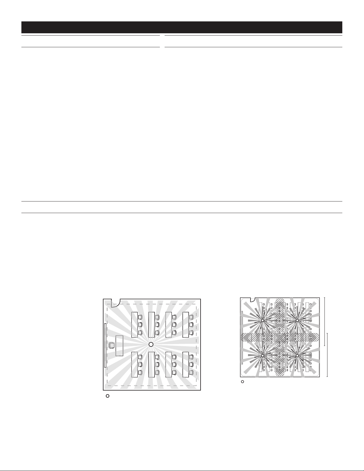
If the space is larger than 30’ x 30’ it will be necessary to
use more than one sensor to ensure complete coverage.
verlap
36'
PIR
Coverage
36 ft
(10.97m)
Ultrasoni
Coverag
36 ft
(10.97m)
Sensor
trasonic
Page 2

Common application – Classroom: Position the sensor so that the maximum
Sensor
36'
36'
(10.97m x 10.97m)
#12 to #16 AWG
Cu Wire Only
Neutral
Neutral
coverage is achievable. Be sure that the sensor is not pointing out the door. To get
complete coverage in an open office area, install multiple sensors so that there is
approximately 20% overlap with each adjacent sensor’s ultrasonic coverage area.
COVERAGE PATTERN
The DT-355 provides a 360° coverage pattern. The
coverage shown represents walking motion at a mounting
height of 8-12 feet. For building spaces with lower levels
of activity or with obstacles and barriers, coverage size
may decrease. The coverage for PIR ONLY trigger mode
varies with mount height. Refer to pattern below for details.
Ultrasonic coverage is roughly the same for 8-12 foot
mount heights. Refer to PIR and Ultrasonic trigger mode
coverage for details.
Top View
PIR
Coverage
Ultrasonic
Coverage
36 ft x 36 ft
8-12 foot Mounting Height
WIRING DIRECTIONS
8ft
(2.4m)
10ft
(3.0m)
12ft
(3.7m)
0
40ft
(12.2m)
36 ft
(10.97m)
30ft
(9.1m)
Side View
20ft
(6.1m)
10ft
(3.0m)
0
10ft
(3.0m)
20ft
(6.1m)
PIR Only Coverage
* Drawings not to scale, representative of PIR
and Ultrasonic Trigger Mode major motion
coverage
30ft
(9.1m)
40ft
(12.2m)
Multiple Sensors Connected in Parallel
Ground
(Optional)
NOTE: This application does not allow for Load to increase
WARNING: DO NOT INSTALL THE SENSOR IN A SPACE
CONTROLLING A TOTAL LOAD THAT IS HIGHER THAN THE RATING
OF THE DEVICE. EACH SENSOR WILL NEED TO SWITCH THE ENTIRE
LOAD EVEN IF ADDITIONAL SENSORS ARE INSTALLED. RISK OF
OVERLOAD, PRODUCT DAMAGE, SMOKE AND/OR FIRE MAY RESULT.
Load
Load
Line
Neutral
Load
Ground
(Optional)
Line
2
Hot
Neutral
WARNING: TURN THE POWER
OFF AT THE CIRCUIT BREAKER
BEFORE INSTALLING SENSORS.
Single Sensor, Single Load
Load
Load Hot
Ground
(Optional)
Strip Gauge
Neutral
Page 3

*
Cover
Wiremold #V5752 box
Ceiling
MOUNTING THE SENSOR
Using a 4-Inch Square Junction Box
1. Pull the line voltage wires into the J-Box through the conduit
knockout.
2. Run the wires through the CA-1 adapter then connect the
line voltage wires to the appropriate terminals on the sensor.
3. Align the CA-1 and the sensor with the J-Box so that the
mounting screw tabs on the box match the mounting holes
on the sensor’s rear housing and the CA-1.
4. Use two machine screws (included with the sensor) to attach
the sensor to the mounting tabs on the J-Box.
5. Snap the front cover onto the sensor.
Mounting to a 4” Square Wiremold V5752 box or 4”
Square Junction Box with Double-Gang Mudring
4" Square
CA-1 Adapter
Rear Housing
Sensor Flange
Screws
Front Cover
Using an Octagonal J-Box
1. Pull the line voltage wires into the J-Box through the conduit
knockout.
2. Connect the line voltage wires to the appropriate terminals
on the sensor.
3. Loosen the appliance mounting screws attached to the J-Box
4. Align the sensor in the J-Box so that the mounting screws on
the box match the key holes on the sensor’s rear housing.
5. Push the sensor up into the J -Box and twist it so that the
mounting screws are seated in the keyhole slots.
6. Tighten the two screws to secure the sensor to the J-Box.
7. Snap the front cover onto the sensor.
Mounting to an Octagonal Junction Box
4" Octagonal, 2.25" Deep
Junction Box
Ceiling
Sensor
Screws
Front
* The Junction Box must be at least 2.25” deep.
If it is not, an extension ring is required.
SENSOR ADJUSTMENT
NOTE: This unit is pre-set for basic operation as described in this guide.
Adjustment is optional.
The sensors are factory preset to allow for quick installation in most
applications. Verification of proper wiring or coverage, or customizing the
sensor’s settings can be done using the following procedures. To make
adjustments, open the Front Cover with a small screwdriver.
There is a 30 second warm-up period when power is first applied.
Before making adjustments, make sure the office furniture is installed,
lighting circuits are turned on, and the HVAC systems are in the overridden/
on position. VAV systems should be set to their highest airflow. Set the Logic
Configuration and Time Delay to the desired settings. See the DIP switch
Configuration Chart.
To Test Occupancy Sensors
1. Ensure the Time Delay is set for Test Mode* using the “Test Mode/20 minutes” setting. (DIP switches 1, 2, & 3 are OFF).
2. Ensure that the Light Level is at default (maximum). Press and hold the pushbutton for 5 seconds or until the Green LED flashes
rapidly. Wait 10 seconds for the flashing to stop.
3. Ensure that the Ultrasonic Sensitivity trimpot is set to about 70%, clockwise.
4. Remain still. The red and green LEDs should not flash. The lights should turn off after 5 seconds. (If not, see “Troubleshooting”).
5. Move around within the coverage area. The lights should come on. Adjust the Ultrasonic Sensitivity as necessary to provide the
desired coverage (Green LED indicates activation from the ultrasonic sensor).
When testing and adjustment is complete, reset DIP Switches and Light Level to the desired settings, and replace the cover on the
sensor.
• Test Mode is a temporary state that starts when you first set the sensor’s DIP switches for the “Test Mode/20 minutes” (switches 1,
2, 3 OFF). If you need to invoke the Test Mode and the DIP switches are already set for Test Mode/20 minutes, toggle DIP switch 1
ON then back to the OFF position. This provides a 10 minute test period. During the test period, the Time Delay is only 5 seconds.
Ultrasonic
sensitivity
trimpot
DIP switches
Ultrasonic
transducer
cones
Ultrasonic
activity
LED (Green)
Light level pushbutton
ECE
8
7
6
5
4
3
ON
2
1
Keyhole slots
(for mounting to
4" octagonal box)
Double gang
mudring
mounting holes
PIR Activity
LED (Red)
PIR lens
3
Page 4

DIP SWITCH SETTING
= OFF
Switch#
Feature
Time Delay: Switches 1, 2, 3
The sensor will hold the lights ON as long as occupancy is detected. The time delay countdown starts
when no motion is detected. After no motion is detected for the length of the time delay, the sensor will turn
the lights OFF.
Walk-through: Switch 4
Walk-through mode turns the lights OFF three minutes after the area is initially occupied, if no motion is
detected after the first 30 seconds. If motion continues beyond the first 30 seconds, the selected time
delay applies.
PIR Sensitivity: Switch 5
• Minimum forces a reduced detection range for the PIR.
• Maximum causes the DT-355 to monitor the controlled environment and automatically select the
maximum sensitivity that will provide reliable operation without false detection. This setting is
constantly updated.
Occupancy Logic: Switches: 6, 7, 8
The DT-355 has 8 logic configurations for occupancy triggers, set with DIP switches 6, 7 & 8. Determine
the appropriate Occupancy Logic Option using the Trigger matrix, then set the DIP switches accordingly.
Initial Occupancy: The method that activates a change from “Standby” (area unoccupied and loads are
OFF) to “Occupied” (area occupied and loads are ON).
• Both requires detection by PIR and Ultrasonic.
• Either requires detection by only one technology.
• PIR requires detection by the PIR.
• Man. requires activation of the Manual Switch. (See Manual ON functions” for further information).
Maintain Occupancy: The method indicating that the area is still occupied and the lights should remain
ON.
Re-trigger: After the time delay elapses and the lights turn OFF, detection by the selected technology
within the number of seconds indicated turns the lights back ON.
Time Delay
Test Mode/20 min
30 seconds
5 minutes
10 minutes
15 minutes
20 minutes
25 minutes
30 minutes
Walk-Through
Enabled
Disabled
PIR Sensitivity
Minimum
Maximum
Settings
Standard
Option 1
Option 2
Option 3
Option 4
Logic
Option 5
Occupancy
Standard
Standard
Trigger
Standard
Occupancy Logic
Both
Option 1
Option 2
PIR
Both PIR Both(5)
Option 3
Option 4
PIR
Option 5
Either
= Factory Setting
= ON
Initial
Occupancy
Maintain
Occupancy
Either
EitherEither
Either
PIR
PIR
123
4
5
67
Re-trigger
Either(5)
Either(5)
Either(5)
PIR(5)
Either(5)
8
duration)
(seconds
LIGHT LEVEL FEATURE
The Light Level feature holds lights off upon initial occupancy if adequate ambient light exists. It will not turn the lights off if they are on.
The default setting is for maximum, meaning that even the brightest ambient light will not hold the lights off.
Notes on Functionality
• Avoid mounting the sensor close to lighting fixtures.
• Adjust during daylight hours when ambient light in the area is at desired level.
• Light Level cannot be enabled while Test Mode is active. Either wait for Test Mode to expire or select any of the other Time Delay
settings before enabling the Light Level feature.
• Ultrasonic occupancy indicator from LED is disabled when the Light Level feature is enabled. PIR occupancy indicator LED may still
respond when lights are being held off. LEDs will also flash periodically to indicate the sensor has Light Level enabled.
• Light Level settings are only saved in the event of a power loss. Disabling Light Level and then reenabling it will not return it to
previous settings.
• If Test Mode is enabled after Light Level has been set, Light Level functionality will cease to function throughout the duration of Test
Mode. When Test Mode period expires, the Light Level functionality will resume, even if the Dip Switches remain set to Test Mode.
Setting Light Level
1. Make sure Test Mode is not active.
2. Toggle the state of the sensor, by briefly pressing the Light Level button, to include or exclude the lighting load from the light level
calibration. Open the Front Cover and locate the Light Level pusbbutton. See Sensor Adjustment.
3. Press and hold the Light Level button for 2 or more seconds, or until the detection LEDs turn On. Do not exceed 5 seconds.*
The sensor enters setup mode, as indicated by the rapidly flashing LEDs. The LEDs will flash throughout the setup process.
Occupancy indications from the LEDs are disabled during setup.
4. Move away from the sensor to avoid interference with light level detection. The sensor measures the light level for a 10 second
period, then averages the readings and automatically sets the level that will be used as the new setting. The sensor will hold lights
off when the ambient light exceeds this setting.
5. When the two LEDs stop flashing, replace the Front Cover.
4
Page 5

Disabling Light Level
Pressing the pushbutton for 5 seconds or more resets the light to default (maximum).
Press and hold the Light Level button for 5 seconds or until the detection LED(s) turn ON and then OFF. The LEDs flash rapidly for 10
seconds after the setting has changed.
TROUBLESHOOTING
For any unexpected operation
1. Check DIP switch settings. Make sure the switches are set according to the defined settings in the DIP Switch Setting chart.
Lights do not turn on when entering the room.
Neither LED Flashes
1. Check that the circuit breaker has been turned back on.
2. Check all sensor connections.
Red LED does not ash
1. When power is initially applied to the sensor, there is a warm-up period of 30 to 60 seconds before the LED becomes active.
2. Make sure PIR sensitivity is set to 100% (DIP switch #5 is in the “off” position).
Green LED is on steady
Check ultrasonic sensitivity trimpot. Fully counterclockwise position is the override for the sensor. Turn trimpot clockwise until LED
flashes only when movement occurs in the desired coverage area.
Red and Green LEDs ash
1. Check all sensor connections.
2. Check if Light Level is enabled.
• If occupancy indicator LEDs blink together every few seconds, sensor is using Light Level feature.
• If Light Level functionality is not desired, press and hold for 5 seconds to return sensor to the default setting (maximum).
Lights do not turn off automatically.
Green LED ashes
Reduce ultrasonic sensitivity by turning adjustment pot counter-clockwise until it only flashes when movement occurs.
Red LED randomly ashes
Set PIR sensitivity to minimum by turning DIP switch 5 to the “on” position.
Lights do not turn off
Check all sensor andconnections.
SERVICE
To override all sensor functions, set the Ultrasonic Sensitivity trimpot to the fully counterclockwise (Service) position.
This bypasses the occupancy control functions of the sensor.
ORDERING INFORMATION
Catalog # Description
DT-355 360° Dual Technology Occupancy Sensor, Line Voltage, w/light level sensor
CA-1 Cosmetic adapter for ceiling installation with 4” square j-box or Wiremold #V5752 box. All sensors are white.
All sensors are White
5
Page 6
INSTRUCTIONS EN FRANÇAIS
36'
36'
36'
20 %
C
d
Portée des
20 %
C
d
es ultrasons
DESCRIPTION DE L’APPAREIL
Les détecteurs de présence à double technologie 360°
DT-355 de Wattstopper associent les technologies
avancées de l’infrarouge passif (IRP) et des ultrasons
dans une seule unité. L’association de ces technologies
permet de contribuer à éliminer les problèmes de faux
déclenchements même dans les applications difficiles.
Le DT-355 allume et éteint les systèmes d’éclairage en
fonction des niveaux de présence et d’éclairage ambiants.
La fonction de niveau d’éclairage peut être utilisée
pour empêcher les lumières de s’allumer si le niveau
d’éclairage ambiant est suffisant.
Le DT-355 propose différents modes de fonctionnement
qui peuvent être associés pour obtenir une régulation
personnalisée idéale. Les détecteurs peuvent être
configurés pour allumer l’éclairage et le maintenir ainsi
tant que l’une des deux ou les deux technologies détectent
une présence. Sans détection de mouvements durant la
temporisation sélectionnée par l’utilisateur, les lumières
s’éteignent. Le mode « passage » permet d’éteindre
les lumières au bout de 3 minutes seulement si aucun
mouvement n’est détecté 30 secondes après la détection
d’une présence.
Le DT-355 fonctionne sur alimentation secteur 120 VCA,
230 VCA (1Ø), 277 VCA, ou 347 VCA.
INSTRUCTIONS DE PLACEMENT
CARACTÉRISTIQUES
Tensions ............................................................. 120//230/277/347 VCA, 50/60 Hz
Exigences en matière de charge
120 VCA ...............................................................0-800 W Ballast/Tungstène/DEL
à 230 VCA (monophasé) .............................................0-1 200 W Ballast/DEL
à 277 VCA ...................................................................0-1 200 W Ballast/DEL
à 347 VCA ...................................................................0-1 500 W Ballast/DEL
Température de fonctionnement ........................................0 à 55 °C (32 à 131 °F)
Couple nominal des bornes................................................... 4,428 po-lb (0,5 N.m)
Réglage du niveau de luminosité en une étape ...............................10 FC–300 FC
Réglage de la temporisation..........................................30 secondes à 30 minutes
Mode passage ...................................... 3 minutes si aucune activité après 30 sec.
Mode test ............................................ 5 sec. après activation de l’interrupteur DIP
Portée IRP (normale) .............................................................................(1 300 pi2)
Réglage de la sensibilité ............................................ Élevée ou faible (réglage de
l’interrupteur DIP)
Portée ultrasonique (normale) ................................................................ (1 300 pi2)
Réglage de la sensibilité .................................Min. à Max. (potentiomètre d’ajustement)
Fréquence .................................................................................................... 40 kHz
UL & CUL listés pour une utilisation avec les blocs d’alimentation Wattstopper
En fonction des obstacles, tels que des meubles ou la disposition de la pièce, la portée de l’unité peut être réduite ou augmentée par
rapport aux distances de perception illustrées dans le schéma de la portée. Cela doit être pris en compte dans le choix du nombre de
détecteurs et de leur placement. Il est également conseillé de placer le détecteur à une distance de 1,2 à 1,8 mètres (4 à 6 pieds)
minimum des conduits d’aération.
Montez le détecteur sur le plafond. Le DT-355 est conçu pour une hauteur de plafond d’environ 2,44 à 3,66 m (de 8 à 12 pi). Le placer à
une hauteur supérieure ou inférieure à celle recommandée affectera de manière significative la portée de l’appareil. En règle générale,
chaque occupant doit être capable de voir clairement le détecteur.
Obstruction de la lentille IRP: du ruban adhésif opaque est fourni de manière à pouvoir masquer des parties de la lentille IRP. Cela
limite le champ de vision du détecteur et permet d’empêcher la portée de l’IRP dans les zones non désirées, telles que des couloirs
hors de la zone de portée souhaitée. Étant donné que cette obstruction diminue la portée, n’oubliez pas d’en tenir compte en cas de
dépannage des problèmes de portée. La portée des ultrasons ne peut pas être bloquée, mais vous pouvez réglez la sensibilité pour
réduire la zone de portée.
Application habituelle –
Salle de classe Placez le
détecteur de telle sorte que
la portée maximum puisse
36'
Portée
IRP 36 pi
(10,97 m)
être obtenue. Assurezvous que le détecteur n’est
pas dirigé vers la porte.
Pour obtenir une portée de
hevauchement
es ultrasons
détection complète dans
un bureau à aires ouvertes,
installez plusieurs détecteurs
de manière à obtenir un
chevauchement d’environ
20 % entre les zones de
portée de deux détecteurs à
ultrasons adjacents.
Détecteur
double technologie
hevauchement
Si l’espace mesure plus de 9,15 m par 9,15 m (30 pi x
30 pi), il sera nécessaire d’utiliser plus d’un détecteur
ultrasons
36 pi
(10,97 m)
pour assurer une portée sur l’ensemble de l’espace.
6
Page 7

PORTÉE
12.2m
(40pi)
(10.97m)
(10.97m x 10.97m)
#12 à #16 AWG
Câble en cuivre uniquement
Neutre
Neutre
Le DT-355 présente une portée à 360°. La portée indiquée
dans le schéma représente un mouvement de marche
pour une hauteur de montage de 2,44 à 3,66 mètres
(8-12 pi). Pour les bâtiments avec une activité plus faible
ou avec des obstacles et barrières, la zone de portée
risque de diminuer. La portée en mode de déclenchement
par IRP UNIQUEMENT varie selon la hauteur de
montage. Consultez le schéma ci-dessous pour plus de
renseignements. La portée ultrasonique est à peu près la
même lorsque la hauteur de montage se trouve entre 2,44
et 3,66 mètres (8 et 12 pi). Consultez la partie concernant le
mode de déclenchement par IRP et ultrasons pour plus de renseignements.
Vue du haut
IRP
Portée
Ultrasons
Portée
36 pi x 36 pi
2.4m
(8pi)
3.0m
(10pi)
3.7m
(12pi)
0
12.2m
(40pi)
9.1m
(30pi)
Vue latérale
6.1m
(20pi)
3.0m
(10pi)
Portée de l’IRP seul
36 pi
Hauteur de montage de 2,44 à 3,66 m
(de 8 à 12 pi)
0
3.0m
(10pi)
6.1m
(20pi)
9.1m
(30pi)
Les schémas ne sont pas à l’échelle
et représentent la portée principale
du mode de déclenchement des
ultrasons et du système IRP
INSTRUCTIONS DE CÂBLAGE
ATTENTION: NE PAS INSTALLER LE DÉTECTEUR DANS UN
ESPACE CONTRÔLANT UNE CHARGE TOTALE SUPÉRIEURE À
LA VALEUR NOMINALE DE L’APPAREIL. CHAQUE DÉTECTEUR DEVRA
PRENDRE ACTIVER TOUTE LA CHARGE MÊME SI DES DÉTECTEURS
SUPPLÉMENTAIRES SONT INSTALLÉS. RISQUE DE SURCHARGE,
D’ENDOMMAGEMENT DU PRODUIT, DE FUMÉE ET / OU D’INCENDIE.
Plusieurs détecteurs connectés en parallèle
Charge
Sous tension
Charge
Terre
(en option)
Secteur
Neutre
AVERTISSEMENT: Cette application ne permet pas d’augmenter la charge
Charge
Terre
(en option)
Secteur
Neutre
ATTENTION: COUPEZ
L’ALIMENTATION DU DISJONCTEUR
AVANT D’INSTALLER LES DÉTECTEURS.
Détecteur seul, charge seule
Charge
Charge
Sous tension
Terre
(en option)
Gabarit de dénudage
Neutre
7
Page 8

MONTAGE DU DÉTECTEUR
Plafond
Collerette du détecteur
Boîtier de raccordement
e
Potentiomètre
de l’activité
Avec un boîtier de raccordement carré de 10,16 cm de
côté (4 po)
1. Acheminez les fils de tension de ligne dans le boîtier de
raccordement par l’alvéole sectionnable du conduit.
2. Passez les fils dans l’adaptateur CA-1 puis connectez les fils
de tension de ligne aux bornes correspondantes du détecteur.
3. Alignez l’adaptateur CA-1 et le détecteur avec le boîtier de
raccordement de sorte que les pattes de fixation du boîtier
correspondent aux trous de montage de la partie arrière du
boîtier du détecteur et de l’adaptateur CA-1.
4. Utilisez deux vis à métaux (fournies avec le détecteur)
pour fixer le détecteur aux pattes de fixation du boîtier de
raccordement.
5. Clipsez le couvercle frontal sur le détecteur.
Fixation sur un boîtier carré Wiremold V5752 de 10,16 cm de côté
(4 po) ou sur un boîtier de raccordement carré de 10,16 cm de
côté (4 po) avec orices de montage du cadre doubles
10,16 cm (4 po.) carré
10,16cm (4po) carrée
Adaptateur CA-1
Avec un boîtier de raccordement octogonal
1. Acheminez les fils de tension de ligne dans le boîtier
de raccordement par l’alvéole sectionnable du conduit.
2. Raccordez les fils de tension de ligne aux bornes
correspondantes du détecteur.
3. Alignez le détecteur dans le boîtier de raccordement
de sorte que les pattes de fixation du boîtier
correspondent aux fentes en trou de serrure du boîtier
arrière du détecteur.
4. Utilisez deux vis à métaux (fournies avec le boîtier de
raccordement) pour fixer le détecteur aux pattes de
fixation du boîtier de raccordement.
5. Clipsez le couvercle frontal sur le détecteur.
Fixation sur un boîtier de raccordement octogonal
octogonal de 10,16cm
(4po) par 5,72cm
(2,25po) de profondeur*
Plafond
Boîtier arrière
Vis
Couvercle frontal
RÉGLAGE DU DÉTECTEUR
NOTE: L’unité est préréglée pour un fonctionnement de
base, comme décrit dans ce guide. LE RÉGLAGE EST
OPTIONNEL.
Les détecteurs sont préréglés en usine afin de vous permettre de
l’installer rapidement dans la plupart des applications. Pour vérifier que le
câblage ou la portée sont corrects, ou pour personnaliser les réglages du
détecteur, suivez les procédures suivantes. Pour effectuer les réglages,
ouvrez le couvercle frontal en tirant sur les pattes du couvercle.
Lorsque l’unité est mise sous tension pour la première fois, elle passe
tout d’abord par une période de réchauffement de 30 secondes.
Avant d’effectuer des réglages, assurez-vous que les meubles de la zone
de travail sont installés, que les circuits d’éclairage sont allumés et que
les systèmes CVCA sont en position neutralisé/marche. Les systèmes
DAV doivent être réglés sur le débit d’air le plus important. Paramétrez
la configuration logique et la temporisation en adoptant les réglages
souhaités. Consultez le « Tableau des configurations logiques ».
Pour tester les détecteurs de présence
1. Assurez-vous que la temporisation est réglée sur le Mode Test* en utilisant le réglage « Mode test/20 minutes ». (Interrupteurs
DIP 1, 2 et 3 sur ARRÊT).
2. Assurez-vous que le niveau de luminosité est sur son réglage par défaut (maximum). Appuyez sur le bouton poussoir et
maintenez-le enfoncé pendant 5 secondes ou jusqu’à ce que la DEL verte clignote rapidement. Attendez 10 secondes jusqu’à la
fin du clignotement.
3. Assurez-vous que le potentiomètre d’ajustement de la sensibilité aux ultrasons est placé à environ 70 % dans le sens horaire.
4. Restez immobile. Les DEL rouge et verte ne doivent pas clignoter. Les lumières doivent normalement s’éteindre au bout de 5
secondes. (Dans le cas contraire, voir « Dépannage ».)
Détecteur de présenc
Vis
Couvercle
* Le boîtier de raccordement doit avoir une profondeur d’au
moins 5,72 cm (2,25 po) Dans le cas contraire, un anneau de
prolongement est requis.
d’ajustement
de la sensibilité
aux ultrasons
Interrupteurs DIP
Cônes du
transducteur
à ultrasons
DEL de l’activité
ultrasonique (verte)
Bouton-poussoir du
niveau de luminosité
ECE
8
7
6
5
4
3
MARCHE
2
1
Fentes en trou de serrure
[pour le montage sur la boîte
octogonale de 10,16 cm (4 po)]
8
Orifices de montage
du cadre doubles
DEL
IRP (rouge)
Lentille PIR
Page 9

5. Déplacez-vous dans la zone de portée. Les lumières doivent s’allumer. Réglez la sensibilité ultrasonique comme nécessaire pour
= ARRÊT
Paramètre
obtenir la portée désirée (la DEL verte indique l’activation du détecteur d’ultrasons).
Lorsque le test et le réglage sont terminés, paramétrez de nouveau les interrupteurs DIP et le niveau d’éclairage avec les réglages
souhaités et remettez le couvercle sur le détecteur.
• Le Mode Test est un état temporaire qui démarre lorsque vous mettez les interrupteurs DIP du détecteur sur le « Mode test/20
minutes » pour la première fois (interrupteurs 1, 2 et 3 sur ARRÊT). Si vous avez besoin de lancer le Mode test et que les
interrupteurs DIP sont déjà réglés sur le Mode Test/20 minutes, faites basculer l’interrupteur DIP 1 sur MARCHE, puis de nouveau
sur ARRÊT. Cette action fournit une période de test de 10 minutes. Pendant cette période de test, la temporisation n’est que de 5
secondes.
RÉGLAGE DE L’INTERRUPTEUR DIP
Temporisation : Interrupteurs 1, 2, 3
Le détecteur maintient les lumières ALLUMÉES tant qu’une présence est détectée. Le compte à
rebours de temporisation démarre lorsqu’aucun mouvement n’est détecté. En l’absence de mouvement
pendant toute la durée de la temporisation, le détecteur ÉTEINT les lumières.
Mode passage : Interrupteur4
Le mode passage COUPE l’éclairage trois minutes après la première détection de présence, si aucun
mouvement n’est détecté après les 30 premières secondes. Si le mouvement persiste au-delà des 30
premières secondes, la temporisation sélectionnée se déclenche.
Sensibilité IRP Interrupteur 5
• Minimum impose une réduction de la portée de détection de l’IRP.
• Maximum oblige le DT-355 à surveiller l’environnement contrôlé et à choisir automatiquement la
sensibilité maximum qui garantit un fonctionnement fiable sans fausse détection. Ce réglage est
constamment mis à jour.
Logique de présence : Interrupteurs : 6, 7, 8
Le DT-355 a 8 configurations logiques de déclencheurs de présence, correspondant aux interrupteurs
DIP 6, 7 et 8. Déterminez l’option de logique de présence adaptée en vous servant du tableau des
types de déclenchement, puis réglez les interrupteurs DIP en conséquence.
Présence initiale : permet de passer du mode « Veille » (zone non occupée et charges COUPÉES) à «
Occupé » (zone occupée et charges ACTIVÉES).
• Les deux impliquent que la détection s’effectue via IRP et ultrasons.
• L’un ou l’autre implique que la détection s’effectue via l’une des deux technologies.
• IRP indique que la détection s’effectue uniquement par IRP.
• Man. nécessite une activation de l’interrupteur manuel. (Voir « Fonctions de MARCHE manuelle »
pour plus d’informations.)
Maintien de la présence : méthode qui indique que la zone est toujours occupée et que les lumières
doivent rester ALLUMÉES.
Re-déclenchement : après l’expiration de la temporisation et l’EXTINCTION des lumières, la détection
par la technologie choisie avant la fin du délai indiqué en secondes RALLUME les lumières.
Déclencher
Standard
Option 1
Option 2
Option 3
Option 4
Logique de présence
Option 5
Temporisation
Mode test/20 min
30 secondes
5 minutes
10 minutes
15 minutes
20 minutes
25 minutes
30 minutes
Mode passage
Sensibilité IRP
Minimum
Maximum
Activé
Désactivé
Réglages
Standard
Option 1
Option 2
Option 3
Option 4
Option 5
présence
Logique de
Standard
Standard
Maintenir
Présence
Initiale
L’un ou
Les
l’autre
deux
L’un ou
L’un ou
l’autre
l’autre
L'un ou
IRP
l’autre
Les
IRP
deux
IRP
IRP
L’un ou
IRP
l’autre
= Réglage d’usine
= MARCHE
la présence
N° d’interrupteur
123
4
5
67
Re-déclen-
chement
L’un ou
l’autre (5)
L’un ou
l’autre (5)
L’un ou
l’autre (5)
L’un ou
l’autre (5)
IRP (5)
L’un ou
l’autre (5)
8
(durée en
secondes)
FONCTION DU NIVEAU DE LUMINOSITÉ
La fonction de niveau de luminosité laisse les lumières éteintes si un éclairage ambiant suffisant existe au moment de la présence
initiale. Elle n’éteindra pas les lumières si elles sont allumées. Le réglage par défaut est au maximum, ce qui signifie que même en cas
d’environnement extrêmement lumineux, les lumières s’allumeront.
Remarques sur le fonctionnement
• Évitez d’installer le détecteur près des luminaires
• Effectuez le réglage pendant la journée, lorsque la luminosité ambiante est au niveau souhaité dans la zone.
• Le niveau de luminosité ne peut pas être activé lorsque le Mode test est en marche. Avant d’activer la fonction de niveau de
luminosité, attendez la fin du Mode test ou sélectionnez un autre réglage de temporisation.
• La DEL du détecteur de présence à ultrasons est éteinte lorsque la fonction de niveau de luminosité est activée. La DEL
du détecteur de présence à IRP peut toujours réagir lorsque les lumières restent éteintes. Les DEL clignotent également
périodiquement pour indiquer que la fonction de niveau de luminosité du détecteur est activée.
• Les réglages du niveau de luminosité sont uniquement sauvegardés en cas de coupure de l’alimentation. Le fait de désactiver puis
réactiver la fonction de niveau de luminosité ne permettra pas de retrouver les réglages précédents.
9
Page 10

• Si le Mode test est activé après l’activation de la fonction de niveau de luminosité, celle-ci cessera de fonctionner pendant toute la
durée du Mode test. Lorsque le Mode test arrive à sa fin, la fonction de niveau de luminosité se réactive, même si les interrupteurs
DIP restent en Mode test.
Réglage du niveau de luminosité
1. Assurez-vous que le Mode test est désactivé.
2. Basculez l’état du détecteur en appuyant brièvement sur le bouton de niveau de luminosité, pour inclure ou exclure la charge
lumineuse du calibrage du niveau de luminosité. Ouvrez le couvercle frontal et localisez le bouton-poussoir du niveau de
luminosité. Voir Réglage du détecteur.
3. Appuyez sur le bouton de réglage du niveau de luminosité et maintenez-le enfoncé pendant 2 secondes ou plus, ou jusqu’à ce
que les DEL de détection s’allument. Ne pas dépasser 5 secondes.* Le détecteur passe en mode de réglage, indiqué par le
clignotement rapide des DEL. Les DEL clignotent pendant toute la procédure de réglage. Les notifications de présence des DEL
sont désactivées pendant le réglage.
4. Éloignez-vous du détecteur pour éviter toute interférence pendant la détection du niveau de luminosité. Le détecteur mesure le
niveau de luminosité pendant 10 secondes, puis fait la moyenne des relevés et règle automatiquement le niveau à utiliser comme
nouveau réglage. Le détecteur laisse les lumières éteintes lorsque la luminosité ambiante est supérieure à ce réglage.
5. Lorsque les deux DEL ne clignotent plus, replacez le couvercle frontal.
Désactivation du niveau de luminosité
Appuyez sur le bouton-poussoir pendant 5 secondes ou plus pour remettre la fonction du niveau de luminosité au réglage par défaut
(maximum).
Appuyez sur le bouton du niveau de luminosité et maintenez-le enfoncé pendant 5 secondes ou jusqu’à ce que la/les DEL de détection
s’ALLUMENT puis s’ÉTEIGNENT. Les DEL clignotent rapidement pendant 10 secondes après le changement du réglage.
DÉPANNAGE
En cas de fonctionnement inattendu
1. Vérifiez les réglages de l’interrupteur DIP.
2. Assurez-vous que les interrupteurs sont réglés d’après les réglages définis dans le tableau des réglages des interrupteurs DIP.
Les lumières ne s’allument lorsque quelqu’un entre dans la pièce.
Aucune des deux DEL ne clignote
1. Vérifiez que le disjoncteur de circuit a bien été réenclenché.
2. Vérifiez tous les raccordements du détecteur.
La DEL rouge ne clignote pas
1. Lorsque le détecteur est mis sous tension pour la première fois, il passe tout d’abord par une période de réchauffement de 30 à 60
secondes avant que la DEL ne s’active.
2. Vérifiez que la sensibilité de l’IRP est réglée sur 100 % (interrupteur DIP 5 en position « Arrêt »).
La DEL verte est constamment allumée
Vérifiez le potentiomètre d’ajustement de la sensibilité ultrasonique. Lorsqu’il est entièrement tourné dans le sens antihoraire, le
détecteur est neutralisé. Tournez le potentiomètre d’ajustement dans le sens horaire jusqu’à ce que la DEL ne clignote qu’en cas de
mouvements dans la zone de portée souhaitée.
Les DEL rouge et verte clignotent
1. Vérifiez tous les raccordements du détecteur.
2. Vérifiez que la fonction niveau de luminosité est bien activée.
• Si les DEL de présence clignotent en même temps à intervalles de quelques secondes, le détecteur utilise la fonction de niveau
de luminosité.
• Si la fonction de niveau de luminosité ne doit pas être utilisée, appuyez sur le bouton et maintenez-le enfoncé 5 secondes pour
remettre le détecteur au réglage par défaut (maximum).
Les lumières ne s’éteignent pas automatiquement.
La DEL verte clignote
Réduisez la sensibilité ultrasonique en tournant le potentiomètre d’ajustement dans le sens antihoraire jusqu’à ce qu’elle ne clignote
qu’en cas de mouvements.
La DEL rouge clignote brièvement et la DEL verte ne clignote pas
Regardez si le raccordement de l’interrupteur manuel a été utilisé. Ne raccordez rien à cette borne si vous n’utilisez pas d’interrupteur
instantané basse tension entre le détecteur et le bloc d’alimentation.
La DEL rouge clignote de manière aléatoire
Réglez la sensibilité de l’IRP au minimum en plaçant l’interrupteur DIP 5 sur la position « marche ».
Les lumières ne s’éteignent pas
Vérifiez tous les raccordements du détecteur.
10
Page 11

ENTRETIEN
Pour neutraliser toutes les fonctions du détecteur, tournez le potentiomètre d’ajustement de la sensibilité ultrasonique complètement
dans le sens antihoraire (Fonctionnement).
Cette action permet d’outrepasser les fonctions de contrôle de la présence par le détecteur, tout en laissant la possibilité de réguler
manuellement les lumières à l’aide d’un interrupteur d’éclairage, si un tel dispositif a été installé.
INFORMATIONS CONCERNANT LES COMMANDES
N° de référence Description
DT-355 Détecteur de présence avec technologie double à 360°, tension secteur, avec détecteur de niveau de luminosité
CA-1 Adaptateur décoratif pour installation sur plafond avec boîtier de raccordement carré de 10,16 cm de côté (4 po) ou
boîtier Wiremold #V5752.
Tous les détecteurs sont blancs.
11
Page 12

Sensor
36'
36'
36'
S
uperposición ultrasónica
INSTRUCCIONES EN ESPAÑOL
DESCRIPCIÓN DE LA UNIDAD
Los sensores de presencia con doble tecnología de 360°
DT-355 Wattstopper combinan tecnologías infrarrojas
pasivas (PIR) con tecnologías ultrasónicas avanzadas en
una unidad. La combinación de estas tecnologías ayuda
a eliminar las falsas activaciones, incluso en aplicaciones
difíciles.
El sensor DT-355 enciende y apaga los sistemas de
iluminación según la presencia y los niveles de luz
ambiental. La función de nivel de luz se puede utilizar
para evitar que las luces se enciendan si el nivel de luz
ambiente es suficiente.
El sensor DT-355 ofrece muchos modos de funcionamiento
que se pueden combinar para crear el control
personalizado ideal. Los sensores pueden configurarse
para encender la iluminación y mantenerla encendida
hasta que una o ambas tecnologías detecten una
presencia. Luego de no detectar movimiento durante el
tiempo especificado por el usuario, las luces se apagan.
El modo de “recorrido” puede apagar las luces después
de solo 3 minutos si no se detecta actividad después de
30 segundos de que se detecte una presencia.
El sensor DT-355 funciona con voltaje de línea de 120 V
CA, 230 V CA (1Ø), 277 V CA o 347 V CA.
GUÍAS PARA LA COLOCACIÓN
ESPECIFICACIONES
Voltajes: ...........................................................120//230/277/347 V CA, 50/60 Hz
Requerimientos de carga
A 120 V CA ..............................................0 a 800 W balasto/tungsteno/LED
A 230 V CA (monofásica) ...................................... 0 a 1200 W balasto/LED
A 277 V CA ............................................................ 0 a 1200 W balasto/LED
A 347 V CA ............................................................ 0 a 1500 W balasto/LED
Temperatura de funcionamiento ....................................... 0° a 55° (32 °a 131° F)
Capacidad nominal de torsión de la terminal
.......................................................4,428 librafuerza por pulgada. (0,5 Nm)
Ajuste de nivel de luz en un paso ...............................................10 FC a 300 FC
Ajuste de la demora de tiempo................................... 30 segundos a 30 minutos
Modo de recorrido .........3 minutos si no hay actividad después de 30 segundos
Modo de prueba ............................ 5 s en el restablecimiento del interruptor DIP
Cobertura PIR (típica) ............................................................................. 1300 ft2
Ajuste de sensibilidad .................... Alto o bajo(configuración del interruptor DIP)
Cobertura ultrasónica (típica) .................................................................. 1300 ft2
Ajuste de sensibilidad .............................................. Mín. a máx. (potenciómetro)
Frecuencia ................................................................................................. 40 kHz
Calificado por UL y CUL para el uso con paquetes de alimentación Wattstopper
Según los obstáculos como muebles o distribución de la habitación, el área de cobertura puede ser menor o mayor que las distancias de
detección que se muestran en el perfil de cobertura. Esto debe considerarse cuando se planifica el número de sensores y su colocación.
También se recomienda colocar el sensor a 4 a 6 pies como mínimo de distancia de los respiraderos de suministro de aire.
Montaje de sensor en cielo raso. El sensor DT-355 está diseñado para una altura de cielo raso de aproximadamente 8 a 12 pies. El
montaje por encima o por debajo de este rango afectará significativamente los diagramas de cobertura. Como regla general, cada
ocupante debería poder ver el sensor claramente.
Enmascaramiento de la lente PIR: Se proporciona una cinta adhesiva opaca para que se puedan enmascarar secciones de la lente
PIR. Esto restringe la visualización del sensor y permite eliminar la cobertura PIR en áreas no deseadas, como los vestíbulos que se
encuentran fuera del área cubierta deseada. Dado que el enmascaramiento quita franjas de cobertura, recuerde tener esto en cuenta al
resolver problemas de cobertura. La cobertura ultrasónica no puede enmascararse, pero se puede ajustar la sensibilidad de esta para
reducir el área de cobertura.
Aplicación común
– Aula: Posicione el
sensor de manera que se
pueda alcanzar el límite
máximo de cobertura.
36'
Cobertura PIR de
36 pies
(10,97 m)
Asegúrese de que el
sensor no apunte hacia
la puerta. Para obtener
una cobertura completa
en un área abierta de
oficina, instale varios
sensores para que haya
un 20% de superposición
aproximadamente con
el área de cobertura
ultrasónica de cada
sensor adyacente.
20 %
Superposición
ultrasónica
sensor
Cobertura
ultrasónica de 36
pies
(10,97 m)
Si el espacio es superior a 30' x 30', se deberá utilizar
más de un sensor para asegurar una cobertura completa.
12
Page 13

PERFILES DE COBERTURA
12.2m
(10.97m)
(10.97m x 10.97m)
Neutro
Calibre AWG n.° 12 a 16
Cable de cobre únicamente
Neutro
El sensor DT-355 proporciona un perfil de cobertura de 360°.
La cobertura que se muestra representa el movimiento de
recorrido a una altura de montaje de 8 a 12 pies. En las áreas
de edificios con menos nivel de actividad o con obstáculos
y barreras, el alcance de la cobertura puede disminuir. La
cobertura para el modo de activación de PIR SOLAMENTE
varía según la altura del montaje. Consulte el siguiente perfil
para obtener información detallada. La cobertura ultrasónica
es aproximadamente la misma para las alturas de montaje de
8 a 12 pies. Consulte la cobertura del modo de activación PIR
y ultrasónica para obtener información detallada.
Vista superior
PIR
Cobertura
Cobertura
Ultrasonica
2.4m
(8ft)
3.0m
(10ft)
3.7m
(12ft)
Vista lateral
0
12.2m
(40ft)
9.1m
(30ft)
6.1m
(20ft)
3.0m
(10ft)
0
3.0m
(10ft)
6.1m
(20ft)
9.1m
(30ft)
(40ft)
Cobertura PIR solamente
Los diagramas no son a escala y son
representativos de la cobertura de
movimiento principal del modo de
activación PIR y ultrasónica
36 ft
36 ft x 36 ft
Altura de montaje 8 a 12 pies
INSTRUCCIONES DE CABLEADO
PRECAUCIÓN: NO INSTALE EL SENSOR DONDE LA CARGA
TOTAL ES SUPERIOR A LA CAPACIDAD DEL DISPOSITIVO. CADA
SENSOR NECESITARÁ MANEJAR TODA LA CARGA, INCLUSO SI SE
INSTALAN SENSORES ADICIONALES. PUEDE PRODUCIRSE UN RIESGO
DE SOBRECARGA, DAÑOS AL PRODUCTO, HUMO Y / O INCENDIO.
Sensores múltiples conectados en paralelo
Carga
Carga
Tierra
(Opcional)
Línea
Neutro
ADVERTENCIA: Esta aplicación no permite un aumento de carga.
Carga
Tierra
(Opcional)
Línea
Vivo
Neutro
PRECAUCIÓN: DESCONECTE LA
ENERGÍA DEL DISYUNTOR ANTES
DE INSTALAR LOS PAQUETES DE
ALIMENTACIÓN,
LOS INTERRUPTORES O LOS SENSORES.
Un sensor, una carga
Carga
Carga Vivo
A tierra
(opcional)
Calibre guía para
pelar cables
Neutro
13
Page 14

MONTAJE DEL SENSOR
Caja Wiremold #V5752
Cielo raso
Cielo raso
Caja de conexiones
togonal de 4" y 2,25"
Ranuras de orificios tipo
Uso de una caja de conexiones cuadrada de 4 in
1. Pase los cables de voltaje de línea hacia dentro de la caja
de conexiones por el troquel del conducto.
2. Pase los cables por el adaptador CA-1 y conecte los cables
de voltaje de línea con las terminales correspondientes del
sensor.
3. Alinee el adaptador CA-1 y el sensor con la caja de
conexiones de modo que las pestañas de los tornillos de
montaje en la caja de conexiones coincidan con los orificios
de montaje en el alojamiento trasero del sensor y del
adaptador CA-1.
4. Use dos tornillos maquinados (incluidos con el sensor)
para fijar el sensor a las pestañas de montaje de la caja de
conexiones.
5. Encastre la cubierta frontal en el sensor.
Montaje en una caja Wiremold V5752 cuadrada de 4" o una caja
de conexiones cuadrada de 4" con marco empotrable para caja de
cables con salida doble
cuadrada de 4"
Adaptador CA-1
Uso de una caja de conexiones octogonal
1. Pase los cables de de voltaje de línea hacia dentro de la
caja de conexiones por el troquel del conducto.
2. Conecte los cables de de voltaje de línea con las terminales
correspondientes del sensor.
3. Alinee el sensor en la caja de conexiones, de modo que las
pestañas de los tornillos de montaje de la caja coincidan
con los orificios del alojamiento trasero del sensor.
4. Use dos tornillos maquinados (incluidos con la caja de
conexiones) para fijar el sensor a las pestañas de montaje
de la caja de conexiones.
5. Encastre la cubierta frontal en el sensor.
Montaje en una caja de conexiones octogonal
oc
de profundidad*
Alojamiento trasero
Brida del sensor
Tornillos
Cubierta frontal
*La caja de conexiones debe tener una profundidad de 2,25"
Sensor
Tornillos
Cubierta
como mínimo. En caso contrario, se necesita un anillo de
extensión.
AJUSTE DEL SENSOR
NOTE: Esta unidad se preconfigura en fábrica para el funcionamiento básico como se describe en esta guía. El ajuste es
opcional.
Los sensores vienen con ajuste predeterminado de fábrica para
permitir una instalación rápida en la mayoría de las aplicaciones.
Con los siguientes procedimientos, se puede verificar que el
cableado o la cobertura sean adecuados o personalizar los ajustes
del sensor. Para hacer ajustes, abra la cubierta frontal tirando de la
lengüeta de la cubierta.
Hay un período de calentamiento de 30 segundos cuando se
emplea la energía por primera vez.
Antes de hacer ajustes, asegúrese de que los muebles de
oficina estén instalados, de que los circuitos de iluminación estén
encendidos y de que los sistemas de HVAC estén en la posición
de anulación/encendido. Los sistemas VAV deben configurarse
con su máximo caudal de aire. Establezca la configuración lógica y
la demora de tiempo en el valor deseado. Consulte el “Cuadro de
configuración lógica”.
Potenciómetro de
sensibilidad
ultrasónica
Interruptores DIP
Conos de
transductor
ultrasónico
LED de
actividad
ultrasónica
(verde)
Botón de nivel de luz
ECE
8
7
6
5
4
3
Encendido
2
1
bocallave (para montaje
en caja octogonal de 4")
Orificios de montaje
del marco empotrable
para caja de cables
con salida doble
LED de actividad
PIR (roja)
Lente PIR
Para probar los sensores de ocupación
1. Asegúrese de que la demora de tiempo se configure para el modo de prueba* mediante la configuración “Modo de prueba/20
minutos”. (los interruptores DIP 1, 2 y 3 están APAGADOS).
2. Asegúrese de que el nivel de luz esté en el valor predeterminado (máximo). Presione y mantenga presionado el botón durante 5
segundos o hasta que la luz LED verde destelle rápidamente. Espere 10 segundos hasta que la luz deje de destellar.
3. Asegúrese de que el potenciómetro de sensibilidad ultrasónica esté configurado en aproximadamente 70 % en el sentido de las
manecillas del reloj.
14
Page 15

4. No se mueva. Las luces LED roja y verde no deberían destellar. Las luces deberían apagarse luego de 5 segundos. (En caso
= APAGADO
Función
contrario, consulte “Solución de problemas”).
5. Desplácese dentro del área de cobertura. Las luces deberían encenderse. Ajuste de la sensibilidad ultrasónica según sea
necesario para proporcionar la cobertura deseada (la luz LED verde indica activación desde el sensor ultrasónico).
Cuando la prueba y el ajuste se hayan completado, restablezca los interruptores DIP y el nivel de luz a las configuraciones deseadas, y
vuelva a colocar la cubierta en el sensor.
• El modo de prueba es un estado temporal que comienza cuando ajusta por primera vez los interruptores DIP del sensor para el
“Modo de prueba/20 minutos” (interruptores 1, 2, 3 apagados). Si usted necesita iniciar el modo de prueba y los interruptores DIP
ya están configurados para el “Modo de prueba/20 minutos”, mueva el interruptor DIP 1 a la posición de ENCENDIDO y, luego, a la
posición de APAGADO. Esto proporciona un período de prueba de 10 minutos Durante el período de prueba, el tiempo de retardo
es de solo 5 segundos.
CONFIGURACIÓN DEL INTERRUPTOR DIP
Tiempo de demora: Interruptores 1, 2, 3
El sensor mantendrá las luces ENCENDIDAS siempre y cuando se detecte una presencia. La
cuenta regresiva del tiempo de retardo se inicia cuando no se detecta movimiento. Si no se detecta
movimiento durante la duración de la demora de tiempo, el sensor APAGA las luces.
Recorrido: Interruptor 4
El modo de recorrido APAGA las luces tres minutos después de que el área esté ocupada
inicialmente, si no se detecta movimiento después de los primeros 30 segundos. Si el movimiento
continúa más allá de los primeros 30 segundos, se aplica el tiempo de retardo seleccionado.
PIR Sensitivity (Sensibilidad PIR): interruptor 5
• El mínimo obliga un rango de detección reducido para la tecnología PIR.
• El máximo hace que el DT-355 supervise el ambiente controlado y que seleccione
automáticamente la sensibilidad máxima que ofrecerá un funcionamiento confiable sin falsas
detecciones. Esta configuración se actualiza constantemente.
Lógica de presencia: Interruptores: 6, 7, 8
El DT-355 tiene 8 configuraciones lógicas para los activadores de presencia establecidas en los
interruptores DIP 6, 7 y 8. Determine la opción de lógica de presencia adecuada usando la matriz
de activación y, luego, configure los interruptores DIP en consecuencia.
Ocupación inicial: El método que activa un cambio de “Espera” (área sin presencia y cargas
APAGADAS) a “Ocupado” (área con presencia y cargas ENCENDIDAS).
Mantener ocupación: El método que indica que el área aún está ocupada, y las luces deberían
permanecer ENCENDIDAS.
Reinicio: Después de que transcurre la demora de tiempo y las luces se APAGAN, la detección
mediante la tecnología seleccionada dentro de la cantidad de segundos indicados ENCIENDE
nuevamente las luces.
• Ambos requieren una detección mediante tecnologías PIR y ultrasónica.
• Cualquiera requiere detección mediante solo una tecnología.
• PIR requiere detección mediante PIR.
• Man. requiere activación del interruptor manual. (Consulte “Función de encendido manual” para
obtener más información).
Tiempo de retardo
prueba/20 min.
Mínimo
Carga
Configuración
inicial
Activador
Estándar
Opción 1
Opción 2
Opción 3
Opción 4
Lógica de presencia
Opción 5
Presencia
Ambas
Cualquiera
PIR
Ambas
PIR
Cualquiera
= ENCENDIDO
Interruptor n.°
123
Modo de
30 segundos
5 minutos
10 minutos
15 minutos
20 minutos
25 minutos
30 minutos
Recorrido
Habilitado
Desactivado
Sensibilidad
del PIR
4
5
7
6
Estándar
Opción 1
Opción 2
Opción 3
Opción 4
Opción 5
de presencia
Estándar
Estándar
inicial
inicial
Mantener
Cualquiera
Cualquiera
Cualquiera
PIR
PIR
PIR
= Configuración de fábrica
8
Reinicio
segundos)
(duración en
Cualquiera (5)
Cualquiera (5)
Cualquiera (5)
Ambas (5)
PIR (5)
Cualquiera (5)
FUNCIÓN DE NIVEL DE LUZ
La función de nivel de luz mantiene las luces apagadas durante la presencia inicial si hay una luz ambiente adecuada. No apagará las
luces si están encendidas. La configuración predeterminada está ajustada al máximo, lo que significa que aun con la luz ambiente más
brillante no se mantendrán las luces apagadas.
Notas sobre la funcionalidad
• Evite montar el sensor cerca de dispositivos de iluminación.
• Realice los ajustes durante el día cuando la luz ambiente en el área esté en el nivel deseado.
• El nivel de luz no se puede activar mientras esté activo el modo de prueba. Espere a que finalice el modo de prueba o seleccione
cualquiera de las configuraciones adicionales de demora de tiempo antes de activar la función de nivel de luz.
• El indicador de presencia ultrasónico de la LED se desactiva cuando se activa la función de nivel de luz. El indicador LED de
presencia PIR quizás aún responda cuando las luces se mantienen apagadas. Las luces LED también destellarán periódicamente
para indicar que el sensor tiene el nivel de luz activado.
• Las configuraciones de nivel de luz solo se guardan en el caso de una pérdida de energía. Si se desactiva el nivel de luz y, luego,
se lo vuelve a activar, esto no restituirá las configuraciones anteriores.
15
Page 16

• Si se activa el modo de prueba después de haber establecido el nivel de luz, la funcionalidad de nivel de luz dejará de funcionar
durante todo el período de duración del modo de prueba. Cuando expire el período del modo de prueba, se reanudará la
funcionalidad de nivel de luz, aun cuando los interruptores DIP permanezcan configurados en el modo de prueba.
Conguración del nivel de luz
1. Asegúrese de que el modo de prueba no esté activo.
2. Alterne el estado del sensor, pulsando brevemente el botón de nivel de luz, para incluir la carga de iluminación en la calibración
del nivel de luz o excluirla de esta. Abra la cubierta frontal y encuentre el botón de nivel de luz. Consulte Ajuste del sensor.
3. Presione y mantenga presionado el botón de nivel de luz durante 2 o más segundos, o hasta que las luces LED de detección se
enciendan. No supere los 5 segundos.* El sensor ingresa al modo de configuración, como lo indican las luces LED que destellan
rápidamente. Las luces LED destellarán durante todo el proceso de configuración. Los indicios de presencia de las luces LED se
desactivan durante la configuración.
4. Aléjese del sensor para evitar la interferencia con la detección de nivel de luz. El sensor mide el nivel de luz durante un período
de 10 segundos, luego realiza un promedio de las lecturas y establece automáticamente el nivel que se utilizará como la nueva
configuración. El sensor mantendrá las luces apagadas cuando la luz ambiente exceda esta configuración.
5. Cuando las dos luces LED dejen de destellar, vuelva a colocar la cubierta frontal.
Desactivación del nivel de luz
Al presionar el botón durante 5 segundos o más, se restablece la luz al valor predeterminado (máximo).
Presione y mantenga presionado el botón de nivel de luz durante 5 segundos o hasta que las luces LED de detección se enciendan y
se apaguen. Las LED destellarán rápidamente durante 10 segundos después de que haya cambiado la configuración.
SOLUCIÓN DE PROBLEMAS
Para cualquier funcionamiento inesperado
1. Verifique la configuración del interruptor DIP.
2. Asegúrese de que los interruptores estén configurados según los ajustes definidos en el cuadro de configuración del interruptor
DIP.
Las luces no se encienden cuando ingresa a la habitación.
Ninguna luz LED destella
1. Verifique que el disyuntor se haya encendido de nuevo.
2. Verifique todas las conexiones del sensor.
La luz LED roja no destella.
1. Cuando se energiza el sensor inicialmente, hay un período de calentamiento de 30 a 60 segundos antes de que la LED se active.
2. Asegúrese de que la sensibilidad PIR esté configurada en 100 % (el interruptor DIP n.º 5 está en la posición de apagado).
La luz LED verde está encendida de manera constante.
Verifique el potenciómetro de sensibilidad ultrasónica. La posición completamente contraria a las manecillas del reloj es la anulación del
sensor. Gire el potenciómetro en el sentido de las manecillas del reloj hasta que la luz LED destelle solamente cuando se produce el
movimiento en el área de cobertura deseada.
Las luces LED rojo y verde destellan
1. Controle todas las conexiones del sensor y del paquete de alimentación.
2. Verifique que el nivel de luz esté activado.
• Si los indicadores LED de presencia parpadean juntos cada unos pocos segundos, el sensor está utilizando la función de nivel
de luz.
• Si no se desea la funcionalidad de nivel de luz, presione y mantenga presionado durante 5 segundos para volver el sensor a la
configuración predeterminada (máximo).
Las luces no se apagan automáticamente.
La luz LED verde destella.
Reduzca la sensibilidad ultrasónica moviendo el potenciómetro de ajuste en sentido contrario a las manecillas del reloj hasta que solo
destelle cuando se produce el movimiento.
La luz LED roja destella brevemente y la luz LED verde no destella.
Verifique que haya utilizado la conexión del interruptor manual. No haga ninguna conexión a esta terminal si no está usando un
interruptor momentáneo de bajo voltaje entre el sensor y el paquete de alimentación.
La luz LED roja destella aleatoriamente.
Fije la sensibilidad PIR al mínimo girando el interruptor DIP 5 a la posición de encendido.
Las luces no se apagan.
Controle todas las conexiones del sensor.
16
Page 17

SERVICIO
Para anular todas las funciones del sensor, ajuste el potenciómetro de sensibilidad ultrasónica completamente en sentido contrario
a las manecillas del reloj (servicio). Esto omite las funciones de control de presencia del sensor, pero permite que las luces puedan
controlarse manualmente con un interruptor de luz, si hay uno instalado.
INFORMACIÓN PARA PEDIDOS
del atenuador Descripción
DT-355 Sensor de presencia con doble tecnología de 360°, voltaje de línea con sensor de nivel de luz
CA-1 Adaptador estético para la instalación en cielo raso con caja de conexiones o caja Wiremold #V5752 cuadradas de 4”.
Todos los sensores son blancos.
WARRANTY INFORMATION INFORMATIONS RELATIVES À LA GARANTIE INFORMACIÓN DE LA GARANTÍA
Wattstopper warranties its products to be free
of defects in materials and workmanship for a
period of five (5) years. There are no obligations
or liabilities on the part of Wattstopper for
consequential damages arising out of, or in
connection with, the use or performance of this
product or other indirect damages with respect
to loss of property, revenue or profit, or cost of
removal, installation or reinstallation.
No. 24038 – 10/17 rev. 3
© Copyright 2017 Legrand All Rights Reserved.
© Copyright 2017 Tous droits réservés Legrand.
© Copyright 2017 Legrand Todos los derechos reservados.
Wattstopper garantit que ses produits sont
exempts de défauts de matériaux et de fabrication
pour une période de cinq (5) ans. Wattstopper
ne peut être tenu responsable de tout dommage
consécutif causé par ou lié à l’utilisation ou
à la performance de ce produit ou tout autre
dommage indirect lié à la perte de propriété, de
revenus, ou de profits, ou aux coûts d’enlèvement,
d’installation ou de réinstallation.
Wattstopper garantiza que sus productos
están libres de defectos en materiales y mano
de obra por un período de cinco (5) años. No
existen obligaciones ni responsabilidades por
parte de Wattstopper por daños consecuentes
que se deriven o estén relacionados con el
uso o el rendimiento de este producto u otros
daños indirectos con respecto a la pérdida
de propiedad, renta o ganancias, o al costo
de extracción, instalación o reinstalación.
800.879.8585
www.legrand.us/wattstopper
 Loading...