

Page 1
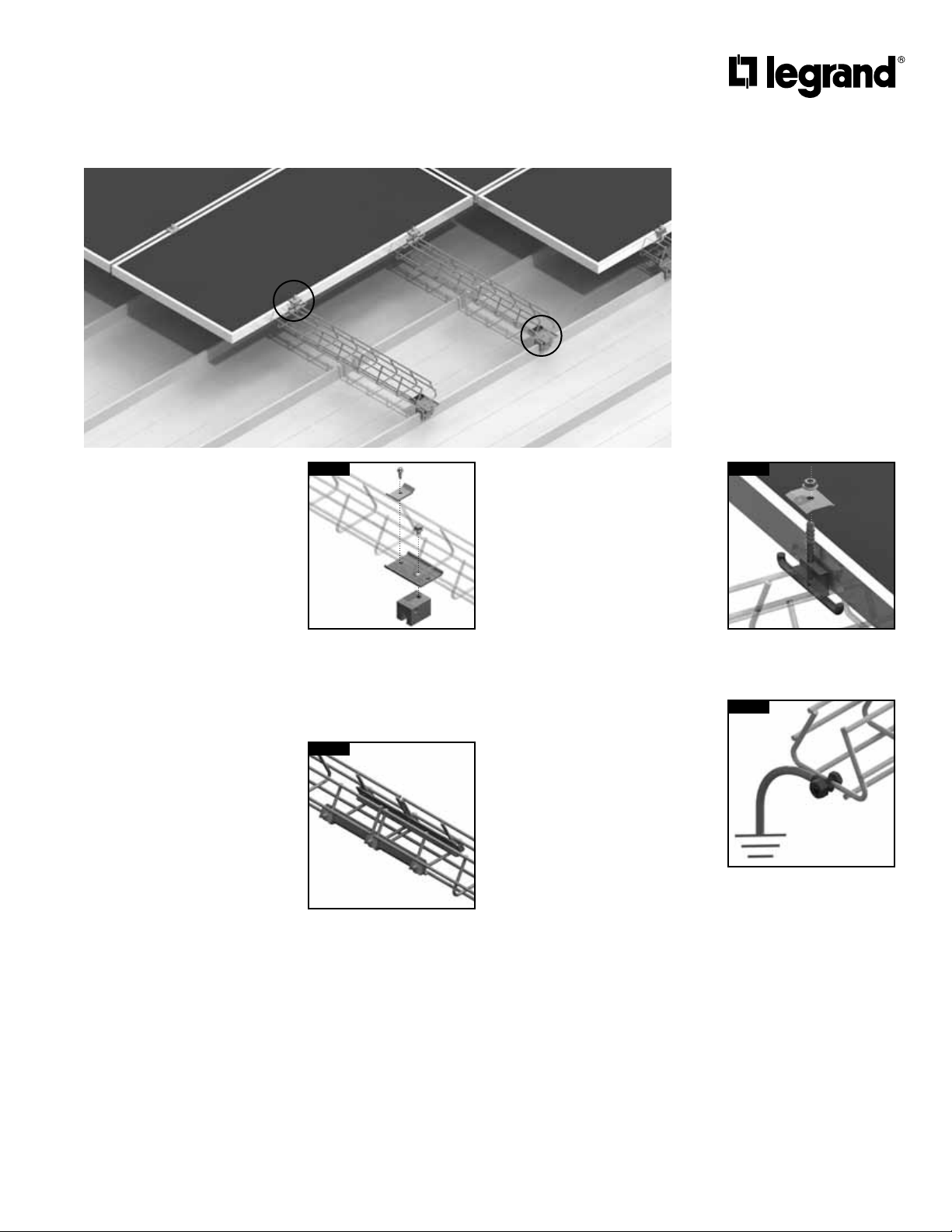
Solar panels supported by Delta Strut
on Metal Raised Seam Roof
C
A
Legrand Delta Strut Solar Systems
have passed electrical/bonding
testing per UL 2703. The following
paragraph states the scope of the
UL standards:
These requirements cover rack
mounting systems and clamping devices
for flat-plate photovoltaic modules and
panels that comply with the standard
for Flat-Plate Photovoltaic Modules
and Panels, UL 1703, intended for
installation on or integral with buildings,
or to be freestanding (i.e., not attached
to buildings), in accordance with the
National Electrical Code, ANSI/NFPA 70
and Model Building Codes.
Installation Instructions:
1. Snap chalk lines for each DS
(Delta Strut) stringer row.
Rows should be located at even
intervals allowing roughly 1/4 of
the total PV length to overhang
the top and bottom stringer
(Allow 1/8” minimum between
panel rows for expansion).
2. Install DS-S5 clamps to roof
seams as required. Install on
roof seams (not exceeding
maximum span of 60” or roof
loading requirements).
3. Attach DSBRSW washer to
DS-S5 seam clamps using
bolt provided. Then attach DS
stringers to DSBRSW/DS-S5
assembly using DSPCC clamp
and self-threading screws
(sold separately). [Figure A]
4. Splice sections of DS together
using a DSSA splice kit (install
splices on both inside corners
of DS for a single splice). Torque
nuts to 6-8 ft/lbs. [Figure B]
FIGURE A
DSPCC
DSBRSW
DS-S5
For optimal holding strength,
screw tension should be 160
to 180 inch pounds on 22
ga. steel and 130 to 150 inch
pounds for all other metals
and thinner gauges of steel.
FIGURE B
DSSA
Use two DSSA to splice any two
sections of Delta Strut tray.
5. Pull string cabling into DS
stringer row.
6. Position first PV panel at the
beginning of first run, checking
for position and square, then
attach to DS using DSEHDC
(End Bolt/Clamp). Torque nuts
to 6-8 ft/lbs.
7. Connect PV cables to stringer
cables and secure cabling to
DS. Be aware that cabling is live
at this point.
8. Add next PV panel in run. Use
DSMHDC (Middle Bolt/Clamp Patent Pending) in areas where
two panels adjoin, ending each
row by utilizing a DSEHDC
(End Bolt/Clamp). Torque nuts
to 6-8 ft/lbs. [Figure C]
9. Each solar row to be connected
to Earth as specified in NEC
using proper sized ground
conductor and UL Listed
Split-bolt lug connected to
Delta Strut. [Figure D]
FIGURE C
DSMHDC is spring-loaded and
stays in position while panels
are positioned.
FIGURE D
Use GNDSB split-bolt lug
grounding connector to
properly ground each solar
support row.
DSMHDC
GNDSB
Page 2
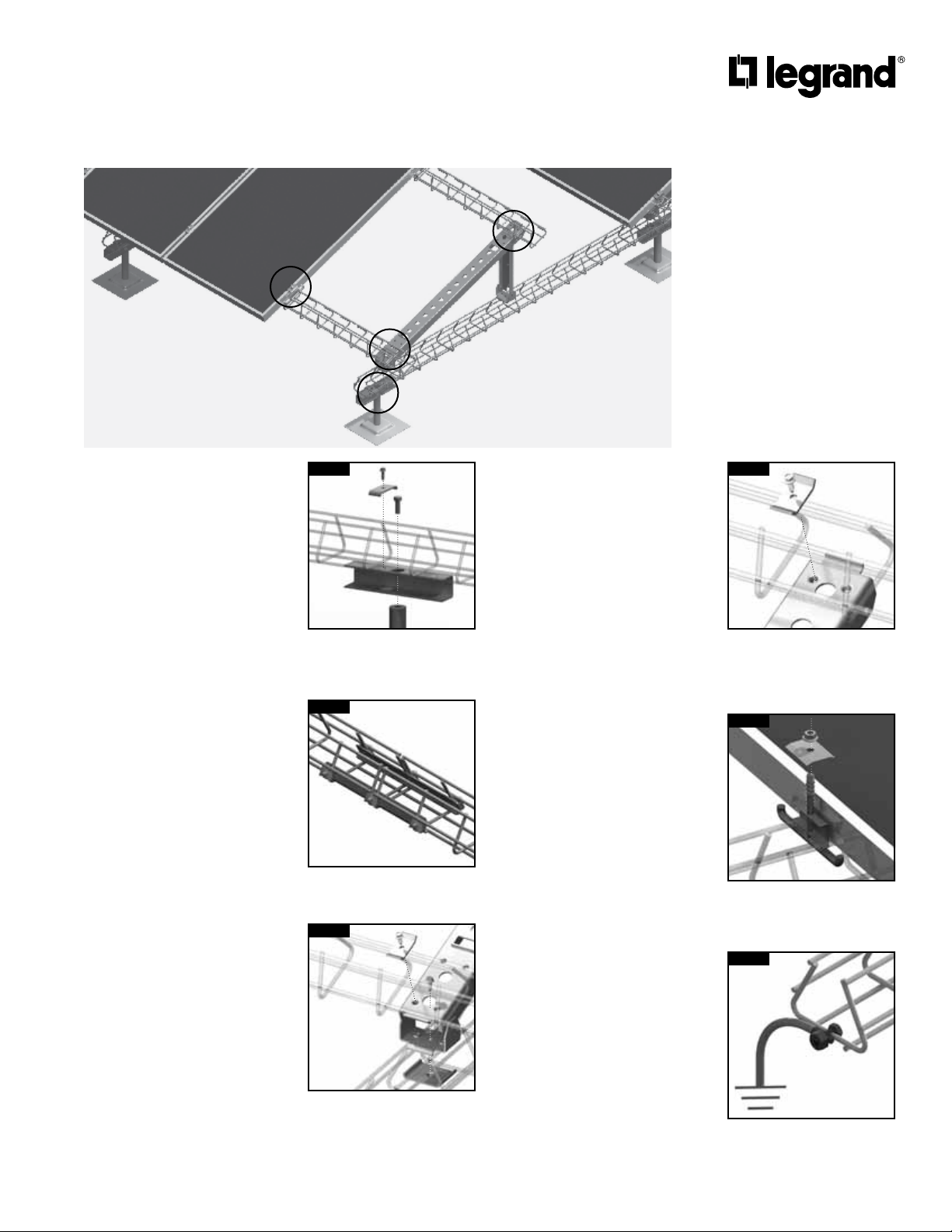
Solar panels mounted to Delta Strut
on Membrane Roof with Stanchions
D
E
C
A
Legrand Delta Strut Solar Systems
have passed electrical/bonding
testing per UL 2703. The following
paragraph states the scope of the
UL standards:
These requirements cover rack
mounting systems and clamping devices
for flat-plate photovoltaic modules and
panels that comply with the standard
for Flat-Plate Photovoltaic Modules
and Panels, UL 1703, intended for
installation on or integral with buildings,
or to be freestanding (i.e., not attached
to buildings), in accordance with the
National Electrical Code, ANSI/NFPA 70
and Model Building Codes.
Installation Instructions:
1. Snap chalk lines for each DS
(Delta Strut) support row.
Rows should be located at
even intervals (not exceeding
maximum span of 60” or roof
loading requirements).
2. Snap a second set of chalk lines
at a right angle to position angle
support legs. Actual spacing
should be in accordance with
the drawings provided with each
DS shipment.
3. Install stanchions along support
row according to manufacturer’s
recommendations and roofing
requirements. Install at even
intervals with (not exceeding
maximum span of 60” or roof
loading requirements).
4. Attach DS to stanchions with
DSPEBK (Pedestal Extension
Bracket Kit). [Figure A]
5. Splice sections of DS together
using a DSSA splice (install
splices on both inside corners
of DS for a single splice). Torque
nuts to 6-8 ft/lbs. [Figure B]
6. Install and splice all DS rows
before beginning next steps.
7. Install DSBEA (Angle Support
Assemblies). Attach rear
support to DS support first by
pivoting leg forward then secure
to DS using clamp and selfthreading screw. Attach front
clamp in the same manner.
[Figure C]
FIGURE A
DSPEBK
Bolt is tightened using socket
wrench or power drill thru
access hole.
FIGURE B
DSSA
Use two DSSA to splice any two
sections of Delta Strut tray.
FIGURE C
DSPCC
DSBEA
DSBPW
Self-threading screw is
tightened using socket wrench
or power drill thru access hole.
8. Install DS stringers to angle
supports. Position DS in angle
bracket saddle, then secure
with a DSPCC (Connection
Clamp and self-threading
screw). [Figure D]
9. Splice sections of DS stringers
together using a DSSA splice
kit (install splices on both
inside corners of DS for a single
splice).
10. Position first PV panel at the
beginning of first run, check for
position and square, then attach
to DS using DSEHDC (End Bolt/
Clamp). Torque nuts to 6-8 ft/lbs.
11. Add next PV panel in run. Use
DSMHDC (Middle Bolt/Clamp Patent Pending) in areas where
two panels adjoin. Torque nuts
to 6-8 ft/lbs. [Figure E]
12. Pull feeder cabling into DS
stringer row. Connect PV cables
to feeder cables and secure
cabling to DS. Be aware that
cabling is live at this point.
13. Each solar row to be connected
to Earth as specified in NEC
using proper sized ground
conductor and UL Listed
Split-bolt lug connected to
Delta Strut. [Figure F]
FIGURE D
Use punched pilot hole on
either side of bracket to allow
connection clamp clearance
from cross wire.
FIGURE E
DSMHDC is spring-loaded and
stays in position while panels
are positioned.
FIGURE F
Use GNDSB split-bolt lug
grounding connector to
properly ground each solar
support row.
DSPCC
DSMHDC
GNDSB
Page 3

Solar panels mounted to Delta Strut
on Membrane Roof with Cablo-Port
supports and hold down stanchions
E
B
D
A
Legrand Delta Strut Solar Systems
have passed electrical/bonding
testing per UL 2703. The following
paragraph states the scope of the
UL standards:
These requirements cover rack
mounting systems and clamping devices
for flat-plate photovoltaic modules and
panels that comply with the standard
for Flat-Plate Photovoltaic Modules
and Panels, UL 1703, intended for
installation on or integral with buildings,
or to be freestanding (i.e., not attached
to buildings), in accordance with the
National Electrical Code, ANSI/NFPA 70
and Model Building Codes.
Installation Instructions:
1. Snap chalk lines for each DS
support row. Rows should be
located at even intervals with
a maximum distance of 60”.
Actual spans should be based
upon roof loading requirements.
2. Snap a second set of chalk lines
at a right angle to position angle
support legs. Actual spacing
should be in accordance with
the drawings provided with each
DS shipment.
3. Position each Cablo-Port
support along support row at
even intervals with a maximum
distance of 60”. Always follow
roof load requirements provided
by a certified engineer. No
gluing is necessary.
4. Install hold down stanchions
along support row
according to manufacturer’s
recommendations and roofing
requirements.
5. Lay-in sections of DS and insert
into metal brackets on top of
the Cablo-Port. Secure with fold
down tabs. [Figure A]
6. Attach DS to hold down
stanchions with DSBRSW
washer and bolt. Torque nuts to
6-8 ft/lbs. [Figure B]
7. Splice sections of DS together
using a DSSA splice kit splice
(install splices on both inside
corners of DS for a single
splice). Install and splice all DS
support rows before beginning
next steps. [Figure C]
FIGURE A
Secure each Cablo-Port using
only a screwdriver.
FIGURE B
DSBRSW
Use DSBRSW washer and bolt
to secure array from wind lift.
FIGURE C
DSSA
Use two DSSA to splice any two
sections of Delta Strut tray.
8. Install DSBEA (Angle Support
Assemblies). Attach rear
support to DS support first by
pivoting leg forward then secure
to DS using clamp and selfthreading screw. Attach front
clamp in the same manner.
[Figure D]
9. Install DS stringers to angle
supports. Position DS in angle
bracket saddle, then secure
with a DSPCC (Connection
Clamp) and self-threading
screw. [Figure D]
10. Splice sections of DS stringers
together using a DSSA splice
(install splices on both inside
corners of DS for a single
splice).
11. Position first PV panel at the
beginning of first run, check for
position and square, then attach
to Delta Strut using DSEHDC
(End Bolt/Clamp). Torque nuts
to 6-8 ft/lbs.
12. Add next PV panel in run. Use
DSMHDC (Middle Bolt/Clamp Patent Pending) in areas where
two panels adjoin. Torque nuts
to 6-8 ft/lbs. [Figure E]
13. Pull feeder cabling into DS
stringer row. Connect PV cables
to feeder cables and secure
cabling to DS. Be aware that
cabling is live at this point.
14. Each solar row to be connected
to Earth as specified in NEC
using proper sized ground
conductor and UL Listed Splitbolt lug connected to Delta
Strut. [Figure F]
FIGURE D
DSPCC
DSBEA
DSBPW
Self-threading screw is
tightened using socket wrench
or power drill thru access hole.
FIGURE E
DSMHDC is spring-loaded and
stays in position while panels
are positioned.
FIGURE F
Use GNDSB split-bolt lug
grounding connector to
properly ground each solar
support row.
DSMHDC
GNDSB
Page 4

Solar panels mounted to Delta Strut
on Membrane Roof with Pan Ballast
D
A
C
Legrand Delta Strut Solar Systems
E
have passed electrical/bonding
testing per UL 2703. The following
paragraph states the scope of the
UL standards:
These requirements cover rack
mounting systems and clamping devices
for flat-plate photovoltaic modules and
panels that comply with the standard
for Flat-Plate Photovoltaic Modules
and Panels, UL 1703, intended for
installation on or integral with buildings,
or to be freestanding (i.e., not attached
to buildings), in accordance with the
National Electrical Code, ANSI/NFPA 70
and Model Building Codes.
Installation Instructions:
1. Snap chalk lines for each DS
support row. Rows should be
located at even intervals with
a maximum distance of 60”.
Actual spans should be based
upon roof loading requirements.
2. Snap a second set of chalk lines
at a right angle to position angle
support legs. Actual spacing
should be in accordance with
the drawings provided with each
DS shipment.
3. Center each pan at the
intersection of each chalk line
to position it at the base of each
angle support leg. Attach DS to
proper sized DSXXX ballast pan
with a DSPCC (clip) and bolt.
[Figure A]
4. Splice sections of DS together
using a DSSA splice (install
splices on both inside corners
of DS for a single splice). Torque
nuts to 6-8 ft/lbs (see image
above). [Figure B]
5. Load DSXXX ballast pans with
concrete ballast on both sides of
DS support row.
6. Install DSBEA (Angle Support
Assemblies). Attach rear
support to DS support first by
pivoting leg forward then secure
to DS using clamp and selfthreading screw. Attach front
clamp in the same manner.
[Figure C]
FIGURE A
Load DSXXX ballast pans
with standard 4” x 8” x 16”
concrete blocks.
FIGURE B
DSSA
Use two DSSA to splice any two
sections of Delta Strut tray.
FIGURE C
DSPCC
DSBEA
DSBPW
7. Install DS stringers to angle
supports. Position DS in angle
bracket saddle, then secure
with a DSPCC (Connection
Clamp) and self-threading
screw. [Figure D]
8. Splice sections of DS stringers
together using a DSSA splice
install splices on both inside
corners of DS for a single
splice).
9. Position first PV panel at the
beginning of first run, check for
position and square, then attach
to Delta Strut using DSEHDC
(End Bolt/Clamp). Torque nuts
to 6-8 ft/lbs.
10. Add next PV panel in run. Use
DSMHDC (Middle Bolt/Clamp Patent Pending) in areas where
two panels adjoin. Torque nuts
to 6-8 ft/lbs. [Figure E]
11. Pull feeder cabling into DS
stringer row. Connect PV cables
to feeder cables and secure
cabling to DS. Be aware that
cabling is live at this point.
12. Each solar row to be connected
to Earth as specified in NEC
using proper sized ground
conductor and UL Listed Splitbolt lug connected to Delta
Strut. [Figure F]
FIGURE D
Use punched pilot hole on
either side of bracket to allow
connection clamp clearance
from cross wire.
FIGURE E
DSMHDC is spring-loaded and
stays in position while panels
are positioned.
FIGURE F
DSPCC
DSMHDC
GNDSB
Self-threading screw is
tightened using socket wrench
or power drill thru access hole.
Use GNDSB split-bolt lug
grounding connector to
properly ground each solar
support row.
Page 5

Solar panels mounted Delta Strut
on Gravel Roof with Concrete Pier Ballast
C
A
Legrand Delta Strut Solar Systems
have passed electrical/bonding
testing per UL 2703. The following
paragraph states the scope of the
UL standards:
These requirements cover rack
mounting systems and clamping devices
for flat-plate photovoltaic modules and
panels that comply with the standard
for Flat-Plate Photovoltaic Modules
and Panels, UL 1703, intended for
installation on or integral with buildings,
or to be freestanding (i.e., not attached
to buildings), in accordance with the
National Electrical Code, ANSI/NFPA 70
and Model Building Codes.
Installation Instructions:
1. Snap chalk lines for each DS
support row. Rows should be
located at even intervals with
a maximum distance of 60”.
Actual spans should be based
upon roof loading requirements.
2. Snap a second set of chalk
lines at a right angle to position
DSCBP10-160 (concrete pier
ballast). Actual spacing should
be in accordance with the
drawings provided with each DS
shipment.
3. Place DSCBP10-160 (concrete
pier ballast) using a dolly (or
transfer bar).
4. Install DS stringers to
DSCBP10-160 concrete pier
ballast. Position DS stringer
over poured-in metal mounting
bracket and secure with a
DSPCC (Connection Clamp) and
self-threading screw. [Figure A]
5. Splice sections of DS together
using a DSSA splice (install
splices on both inside corners
of DS for a single splice). Torque
nuts to 6-8 ft/lbs. [Figure B]
FIGURE A
Concrete pier ballasts are
weather resistant and keep
array in place during high
wind events.
FIGURE B
DSSA
Use two DSSA to splice any two
sections of Delta Strut tray.
6. Position first PV panel at the
beginning of first run, check for
position and square, then attach
to DS using DSEHDC (End Bolt/
Clamp). Torque nuts to 6-8 ft/lbs.
7. Add next PV panel in run. Use
DSMHDC (Middle Bolt/Clamp Patent Pending) in areas where
two panels adjoin. Torque nuts
to 6-8 ft/lbs. [Figure C]
8. Pull feeder cabling into DS
stringer row. Connect PV cables
to feeder cables and secure
cabling to DS. Be aware that
cabling is live at this point.
9. Each solar row to be connected
to Earth as specified in NEC
using proper sized ground
conductor and UL Listed Splitbolt lug connected to Delta
Strut. [Figure D]
FIGURE C
DSMHDC is spring-loaded and
stays in position while panels
are positioned.
FIGURE D
Use GNDSB split-bolt lug
grounding connector to
properly ground each solar
support row.
DSMHDC
GNDSB
Page 6

Roof mounted solar panels supported by
Delta Strut and USS Angle Support
E
A
B/C
Legrand Delta Strut Solar Systems
have passed electrical/bonding
testing per UL 2703. The following
paragraph states the scope of the
UL standards:
These requirements cover rack
mounting systems and clamping devices
for flat-plate photovoltaic modules and
panels that comply with the standard
for Flat-Plate Photovoltaic Modules
and Panels, UL 1703, intended for
installation on or integral with buildings,
or to be freestanding (i.e., not attached
to buildings), in accordance with the
National Electrical Code, ANSI/NFPA 70
and Model Building Codes.
Installation Instructions:
1. Snap chalk lines for each
Universal Solar Support (USS)
row. Rows should be located at
even intervals with a maximum
distance of 60”. Actual spans
should be based upon roof
loading requirements.
2. Snap a second set of chalk
lines at a right angle to
correctly position the Delta
Strut stringers. Actual spacing
will vary based upon PV
panes size, angle and shading
requirements.
3. Place USS according to
chalk lines.
4. Load USS with concrete ballast
blocks in each of the three
cavities. Additional ballast can
be added to each USS base by
stacking ballast blocks on both
sides of the base. This should
be done within the loading
requirements of the roof and the
wind requirements of the array.
[Figure A]
5. Install Delta Strut stringers to
angle supports. Position Delta
Strut using the built-in position
tabs, then secure with a DSPCC
Connection Clamp and selfthreading screw. [Figures B, C]
FIGURE A
Load Universal Solar Support
(USS) with standard 4” x
8” x 16” concrete blocks.
Ballast blocks can be
stacked for greater wind load
requirements.
FIGURE B
Position Delta Strut stringers
using built in positioning tabs
on USS.
FIGURE C
DSPCC
6. Splice sections of Delta Strut
together using a DSSA splice
kit. Use both splices in the kit
for a single splice. Torque nuts
to 6-8 ft/lbs. [Figure D]
7. If you are using an Adjustable
Universal Solar Support (USSA),
you can adjust the support
height to make allowances for
low areas in the roof.
8. Attach cable bracing onto rear
and front of USS supports using
Cable Bracing Kit.
9. Place feeder cables into Delta
Strut stringer row(s).
10. Position first PV panel at the
beginning of first run, check for
position and square, then attach
to Delta Strut using DSEHDC
End Bolt/Clamp. Torque nuts to
6-8 ft/lbs.
11. Add next PV panel in run. Use
DSMHDC (Middle Bolt/Clamp Patent Pending) in areas where
two panels adjoin. Torque nuts
to 6-8 ft/lbs. [Figure E]
12. Connect PV cables and secure
cabling to Delta Strut. Be aware
that cabling is live at this point.
13. Each solar row to be connected
to Earth as specified in NEC
using proper sized ground
conductor and UL Listed Splitbolt lug connected to Delta
Strut. [Figure F]
FIGURE D
DSSA
Use two DSSA to splice any two
sections of Delta Strut tray.
FIGURE E
DSMHDC is spring-loaded and
stays in position while panels
are positioned.
FIGURE F
DSMHDC
GNDSB
Use punched pilot hole in USS
to allow connection clamp
clearance from cross wire.
Use GNDSB split-bolt lug
grounding connector to
properly ground each solar
support row.
 Loading...