

Page 1
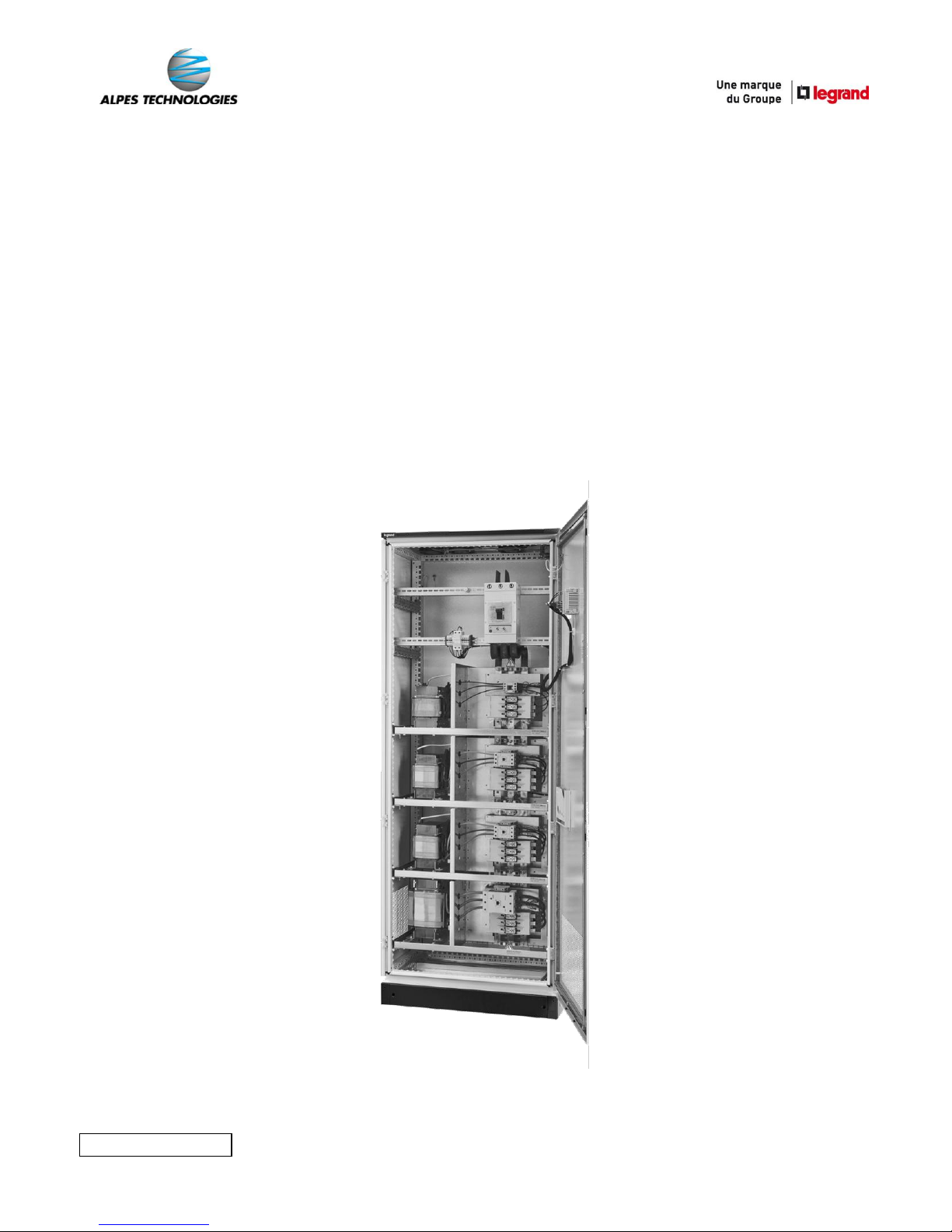
__________________________________________________________________
BATTERIES DE CONDENSATEURS
AUTOMATIQUES ALPIMATIC/BX
Guide d’installation
Installation guide
LE09913AA_1
Page 2

_____________________________________________________________________________________________________
1
Page 3

_____________________________________________________________________________________________________
2
SOMMAIRE GENERAL / GENERAL SUMMARY
CONTENIDO GENERAL / ALGEMENE SAMENVATTING
ОБЩЕЕ РЕЗЮМЕ
Français ..................................................................................................... 04
English ...................................................................................................... 26
Español ..................................................................................................... 48
Nederlands ............................................................................................... 70
Рyccкий .................................................................................................... 92
Page 4

_____________________________________________________________________________________________________
3
Page 5

_____________________________________________________________________________________________________
4
FR
BATTERIES DE CONDENSATEURS
AUTOMATIQUES ALPIMATIC/BX
Guide d’installation
Page 6

_____________________________________________________________________________________________________
5
Page 7

_____________________________________________________________________________________________________
6
FR
SOMMAIRE
1 – Consignes de sécurité .......................................................................... 07
2 – Caractéristiques techniques
A – Batterie de condensateurs automatique
I – Caractéristiques générales ................................................ 09
II – Armoire ............................................................................. 10
III – Condensateurs ALPIVAR/BX ............................................... 10
IV – Gammes ........................................................................... 10
B – Caractéristiques du local d’installation ......................................... 11
C – Kit de sécurité............................................................................... 12
3 – Raccordement
A – Protection .................................................................................... 13
B – Circuit puissance .......................................................................... 13
C – Circuits auxiliaires
I – Raccordement du transformateur de courant T.C ............. 17
II – Fonctionnement sur groupe électrogène ........................... 19
4 – Mise sous tension
A – 1ere mise sous tension ................................................................. 20
B – Contrôle de la position du T.C ...................................................... 21
C – Régulateur ALPTEC
I – Présentation des régulateurs ............................................ 22
II – Descriptif de l’afficheur LCD .............................................. 23
III – Mesures ............................................................................ 24
5 – Maintenance .......................................................................................... 25
Page 8
_____________________________________________________________________________________________________
7
1 – CONSIGNES DE SECURITE
Généralités
Les batteries de condensateurs automatiques doivent être installées conformément aux règles
d’installation qui sont décrites dans les notices. En cas de choc externe, les condensateurs ou
batteries de condensateurs ne doivent ni être connectés ni utilisés.
Une installation et une utilisation incorrectes peuvent entraîner des risques de choc électrique ou
d’incendie. Les batteries de condensateurs doivent être utilisées dans les conditions normales, c’està-dire qu’elles ne doivent pas être soumises à des valeurs de Tension / Courant / Fréquence / Taux
d’harmoniques / Températures autres que spécifiées dans le catalogue commercial et la notice.
Utiliser exclusivement les accessoires préconisés par le groupe Legrand dans le catalogue
commercial et dans les notices.
Soucieux de garantir constamment les meilleurs niveaux de performance de nos produits, ceux-ci
peuvent donc être soumis à des modifications. Merci de vérifier l’exactitude des spécifications produit
lors des opérations d’installation et de mise en service, et de vous reporter aux notices
correspondantes. Pour toute question ou demande de précision, merci de contacter votre
interlocuteur du groupe Legrand.
Les opérations d’installation, d’utilisation et de maintenance d’une batterie de condensateurs
automatique doivent être effectuées par du personnel qualifié, formé et habilité, en accord avec les
règles en vigueur propres à chaque pays.
Toute modification de la batterie de condensateurs automatiques non autorisée
préalablement par le groupe Legrand annule l’intégralité des responsabilités, droits à
remplacement et garanties.
Risques de chocs électriques, de brûlures et d’explosion
Porter les EPI (équipements de protection individuelle) nécessaires aux interventions sur des
produits sous tension.
Respecter les règles de sécurité liées aux travaux électriques.
Un usage électrique et mécanique inapproprié des équipements peut être dangereux et risqué et
peut entrainer des blessures corporelles ou dégâts matériels.
Assurer une bonne mise à la terre des batteries de condensateurs automatiques
Couper toutes les alimentations de la batterie de condensateurs avant d’intervenir sur celle-ci.
Avant toute intervention sur les parties actives, attendre au moins 5 minutes afin que les
condensateurs se déchargent, puis court-circuiter les bornes et mettre le condensateur à la terre.
Lors d’opérations qui impliquent l’accès à l’intérieur de la batterie, prendre garde aux risques de
brûlure avant de toucher les produits ainsi que les parties métalliques (en fonctionnement ou juste
après l’arrêt de la batterie).
Avant de remettre la batterie sous tension s’assurer que toutes les protections physiques ont été
remises en place (exemple : écran, capotage, porte).
Tout manquement à la stricte application des procédures et avertissements peut induire à une
défaillance prématurée, explosion, ou départ de feu de l’équipement.
Page 9
_____________________________________________________________________________________________________
8
FR
Limites de garanties / Responsabilités
Les points listés ci-après s'appliquent à tous les produits nommés dans cette publication et à tout autre
support technico-commercial du groupe Legrand :
Les recommandations de cette publication sont basées sur notre connaissance des conditions
typiques d’utilisation de nos produits dans les domaines d’application usuellement rencontrés.
Cependant, il incombe toujours au client de vérifier et valider que les produits de Legrand (avec les
spécifications techniques décrites) sont adaptés à son installation.
Pour les applications qui requièrent un niveau de sécurité très élevé (ex : dans lesquelles la
défaillance d’un composant peut mettre en danger la vie du personnel ou sa santé), le client doit
s’assurer des bonnes pratiques d’installation, de maintenance et d’exploitation du matériel pour éviter
tout risque de blessure du personnel ou dégât matériel en cas de défaillance du produit.
Les règles de stockage, manutention, installation, maintenance ainsi que les précautions et
avertissements adéquats doivent être observés et appliqués.
Page 10
_____________________________________________________________________________________________________
9
2 – CARACTERISTIQUES TECHNIQUES
A – BATTERIE DE CONDENSATEURS AUTOMATIQUE :
I – Caractéristiques générales :
Etiquette signalétique :
o N° (lot de fabrication + référence produit)
o Puissance (kVAr)
o Tension (V)
o Intensité (A)
o Fréquence (Hz)
o Phases
o Isolement (KV)
o Puissance gradin
o Réf (référence produit fini)
Voir l’étiquette à l’intérieur de l’armoire pour le détail des valeurs.
Facteur de perte : 2 W/kVAr (sans self), 6 W/kVAr (avec self)
Température maximale de fonctionnement à l’intérieur de armoire : +45°C
Température moyenne de fonctionnement à l’intérieur armoire sur 24H : 40°C
Conformité norme : CEI 61439- 2 et CEI 61921
Détails des gradins :
Condensateurs simple Condensateurs avec self anti harmoniques
Fusibles de
protection
Contacteur avec
auxiliaire de
commande
Self anti
harmonique
Condensateur
Page 11
_____________________________________________________________________________________________________
10
FR
II – Armoire :
Enveloppe :
o Indice de protection : IP 30
o Tenue aux chocs mécaniques : IK 10
o Couleur armoire : RAL 7035 + socle noir
(1)
Borniers contacts groupe électrogène : OUI
(2)
Borniers contacts raccordement secondaire du T.C. : OUI
(2)
Borniers contacts + kit de sécurité détection de fumée : OUI
(2)(3)
III – Condensateurs ALPIVAR/BX :
Tolérance de capacité : ± 5%
Surtension admissible : 1.18 x Un (12/24 H)
Conformité norme : CEI 60831-1/2
IV – Gammes :
Type
THDu (%)
THDi (%)
SH/ST (%)
S
≤ 3
≤ 10
≤ 15
H
≤ 4
≤ 15
≤ 25
SAH
(4)
≤ 6
≤ 30
≤ 35
SAH renforcé
(4)
≤ 8
≤ 40
≤ 50
SAH sur-renforcé
(4)
≤ 11
(5)
≤ 55
(5)
≤ 65
(5)
THDu : taux de distorsion harmonique en tension
THDi : taux de distorsion harmonique en courant
SH : puissance foisonnée des générateurs d’harmoniques présents au secondaire du
transformateur HTA/BT à compenser (en kVA)
ST : puissance du transformateur (en kVA)
(1)
Sauf sur les armoires dont la puissance est ≤ 125 kVAr.
(2)
Voir le chapitre raccordement/circuits auxiliaires page 16 pour plus d’informations.
(3)
Non inclus dans les armoires sans selfs de hauteur 770 mm, en version avec disjoncteur avec une puissance ≤ 125 kVAr,
en Version sans disjoncteur avec une puissance ≤ 150 kVAr.
(4)
Armoire avec self anti-harmoniques, vérifiez la compatibilité de fréquence avec votre fournisseur d’électricité. Pour d’autres
fréquences, veuillez consulter votre interlocuteur du groupe Legrand.
(5)
A partir de ce niveau d’harmoniques, veuillez consulter votre interlocuteur du groupe Legrand pour réaliser un audit sur
l’installation et vous proposer une solution adaptée à vos besoins (compensation, traitement d’harmoniques).
Page 12
_____________________________________________________________________________________________________
11
B - CARACTERISTIQUES DU LOCAL D’INSTALLATION
Les préconisations ci-dessous garantissent le bon fonctionnement de la batterie de
condensateurs :
Température mini/maxi : -5°C à + 40°C
Température moyenne sur 24H : +35°C
Altitude maxi ≤ 2000 m
Environnement :
o Taux d’humidité maximum ≤ 80 %
o Exempt de poussière
o Pas de présence de produits corrosifs.
Ventilation :
o Espacement mini de 200 mm impératif au niveau des ouïes de ventilation
(mur, plafond, autres éléments).
o Les entrées et sorties d’air ne doivent pas obturées.
o La ventilation de la batterie de condensateurs s’effectue par flux d’air :
Entrée en partie inférieure, les ouïes d’aération se situent sur les faces
Avant et Arrière ainsi que sur les cotés.
Sortie en partie supérieure :
Batteries sans selfs anti-harmonique extraction
naturelle par les ouïes en faces Avant et Arrière ainsi
que les cotés.
Batteries avec selfs anti-harmonique extraction
forcée
(1)
par les ventilateurs situés sur le toit de l’armoire.
(1)
Extraction naturelle pour les armoires type SAH ayant une puissance ≤ 150 kVAr
Tout manquement à la stricte application des procédures et avertissements peut
induire à une défaillance prématurée, explosion, ou départ de feu de l’équipement, et
entrainera automatiquement la perte de la garantie de l’armoire
Page 13
_____________________________________________________________________________________________________
12
Il est nécessaire d’effectuer les opérations suivantes pour garantir le bon
fonctionnement du kit de détection :
Effectuer une maintenance annuelle (nettoyage, resserrage) sur le kit de sécurité.
Effectuer un contrôle annuel des détecteurs de fumée.
Effectuer le changement du détecteur de fumée selon les préconisations du guide
de maintenance.
Tout manquement à la stricte application des procédures et avertissements peut
induire à une défaillance prématurée, explosion, ou départ de feu de l’équipement,
et entrainera automatiquement la perte de la garantie de l’armoire
FR
C – KIT DE SECURITE
Les batteries sont équipées de série d’un kit de sécurité
(1)
:
Chaque cellule est équipée de son propre détecteur de fumée.
En cas de détection de fumée par le kit de sécurité :
o Coupure de l’alimentation du régulateur “ALPTEC”.
o Les contacteurs passent en position “ouvert”.
o Activation du buzzer
(2)
en façade de l’armoire avec émission d’un signal
sonore et visuel.
o Ouverture d’un contact NF repéré “X1/X2” pour permettre une signalisation
à distance. Cette signalisation doit être impérativement exploitée par le
client.
o Coupure de la ventilation
(3)
.
Maintien du défaut jusqu’à la coupure de la batterie
(4)
.
(1)
Non inclus dans les armoires sans selfs de hauteur 770 mm, en version avec disjoncteur avec une puissance ≤ 125 kVAr,
en version sans disjoncteur avec une puissance ≤ 150 kVAr.
(2)
Référence Legrand : 041525
(3)
Pour les armoires avec ventilation forcée.
(4)
Veuillez consulter votre interlocuteur du groupe Legrand pour effectuer un diagnostic de votre armoire de compensation
impactée.
Attention, la batterie peut toujours être sous tension même si le régulateur est éteint.
Page 14

_____________________________________________________________________________________________________
13
3 – RACCORDEMENT
A - PROTECTION
Les batteries de condensateurs non équipées de série d’un système de protection général doivent
obligatoirement en posséder un. Il devra être installé au départ du câble d'alimentation avec :
Un disjoncteur :
o à relais thermique
(1)
avec un réglage au minimum de 1.4 x In
o à relais magnétique
(1)
avec un réglage entre 8 et 10 x In
Un interrupteur-fusibles HPC type gG, le calibre étant au minimum de 1.4 x In
B – CIRCUIT PUISSANCE
Veuillez respecter les préconisations suivantes pour le raccordement des batteries de
condensateurs à l’alimentation générale :
Le raccordement doit être réalisé avec des câbles de puissance dimensionnés au
minimum pour :
I = 1.43 x In
(2)
Le calcul de la section doit tenir compte des coefficients habituels liés à la nature
des câbles :
o Type
o Longueur
o Mode de pose
Le raccordement des phases L1/L2/L3 doit être respecté suivant le repérage du jeu de
barres interne.
Pour les armoires composées de plusieurs cellules, le jeu de barres dans chaque
cellule doit être obligatoirement raccordé à l’alimentation amont par le biais de
câbles de puissances de même quantités et sections afin de garantir une
répartition équilibrée des courants
(1)(3)
.
La mise à la terre de la batterie de condensateurs doit être réalisée avec un câble de
section conforme à la norme en vigueur.
(1)
Pour tout aide au choix, vous pouvez consulter le tableau en page 14.
(2)
Voir page 14 le tableau des sections préconisés pour les câbles d’alimentation.
(3)
Sauf sur les versions avec système de protection général intégré.
Page 15

_____________________________________________________________________________________________________
14
FR
Préconisations des sections des câbles d’alimentation
(1)
:
Puissance
400V
(kVAr)
In
(A)
Protection
De tête
(2)
Calibre
In (A)
Réglage
thermique
Ir (A)
Section
armoire
simple
(mm²)
Section
armoire
double
(mm²)
Section
armoire
triple
(mm²)
10
14
DPX3 160
25
20 4 - - 15
22
DPX3 160
40
32 6 - - 20
29
DPX3 160
40
40
10 - -
25
36
DPX3 160
63
50
16 - -
30
43
DPX3 160
63
63
16 - -
35
51
DPX3 160
80
80
25 - -
40
58
DPX3 160
80
80
25 - -
47.5
69
DPX3 160
100
100
35 - -
50
72
DPX3 160
100
100
35 - -
60
87
DPX3 160
125
125
50 - -
67.5
97
DPX3 160
160
128
50 - -
75
108
DPX3 160
160
160
70 - -
80
115
DPX3 160
160
160
70 - -
87.5
126
DPX3 250
200
180
95 - -
100
144
DPX3 250
200
200
95 - -
112.5
162
DPX3 250
250
225
150 - -
125
180
DPX3 250
250
250
150 - -
150
217
DPX3 630
400
300
185 - -
175
253
DPX3 630
400
350
240 - -
200
289
DPX3 630
400
400
300 - -
225
325
DPX3 630
630
441
400 - -
250
361
DPX3 630
630
504
400 - -
275
397
DPX3 630
630
567
500 - -
300
433
DPX3 630
630
599
630
2x(1x240)
-
325
469
DPX3 630
630
630
630
2x(1x300)
-
350
505
DPX3 1600
800
720
2x400
2x(1x400)
-
375
541
DPX3 1600
800
760
2x400
2x(1x400)
-
400
577
DPX3 1600
800
800
2x400
2x(1x400)
-
450
650
DPX3 1600
1000
900
2x500
2x(1x500)
-
500
722
DPX3 1600
1000
1000
2x630
2x(1x630)
-
550
794
DPX3 1600
1250
1063
2x630
2x(1x630)
-
600
866
DPX3 1600
1250
1188
3x500
2x(2x400)
3x(1x500)
650
938
DPX3 1600
1250
1250
3x500
2x(2x400)
3x(1x500)
675
974
DPX3 1600
1600
1360
3x630
2x(2x500)
3x(1x630)
700
1010
DPX3 1600
1600
1440
3x630
2x(2x500)
3x(1x630)
750
1083
DPX3 1600
1600
1520
4x500
2x(2x500)
3x(2x400)
800
1155
DPX3 1600
1600
1600
4x630
2x(2x630)
3x(2x400)
850
1227
DMX
3
2000
1700
4x630
2x(2x630)
3x(2x400)
900
1299
DMX
3
2000
1800
4x630
2x(2x630)
3x(2x500)
950
1371
DMX
3
2000
1900
5x630
2x(3x500)
3x(2x500)
1000
1443
DMX
3
2000
2000
5x630
2x(3x500)
3x(2x500)
(1)
Valeurs indicatives basées sur les éléments suivant :
* norme CEI 61439-1 et 60364-5-52
* calcul pour des conducteurs / câbles en cuivre groupés et enfermés avec une température admissible de 70°C et une
température ambiante autour des câbles de 55°C
* la longueur des câbles n’est pas prise en compte
(2)
Les armoires équipées d’une protection de tête sont équivalentes pour les sections d’alimentation à une armoire simple,
même si l’armoire est double ou triple.
Page 16
_____________________________________________________________________________________________________
15
Pour la vérification des couples de serrage suivant le planning de maintenance,
veuillez vous rapporter au guide de maintenance.
Appliquer le bon couple de serrage selon le matériel utilisé pour le raccordement du
circuit de puissance à la batterie de condensateurs.
Couple de serrage raccordement circuit de puissance/batterie de compensation
Type
Couple de serrage maxi
Alimentation par disjoncteurs
DPX3 160
8 N.m
(1)
7 N.m
DPX3 250
10 N.m
DPX3 630
24 N.m
DPX3 1600
14 N.m (x2 vis)
Alimentation sans disjoncteur
Jeu de barres
15 N.m
Accessoire de mesure
T.C.
1 N.m
Bornier Viking
0,8 N.m (pour une section de 2.5mm²)
1,4 N.m (pour une section de 6 mm²)
Vérifier visuellement, à l’aide du vernis présent sur les têtes de vis,
qu’il n’y a pas eu de desserrage.
Vérifier le couple de serrage des bornes des contacteurs.
(1)
En cas d’utilisation de borne à cage
Tout manquement à la stricte application des procédures et avertissements peut
induire à une défaillance prématurée, explosion, ou départ de feu de l’équipement, et
entrainera automatiquement la perte de la garantie de l’armoire
Page 17
_____________________________________________________________________________________________________
16
FR
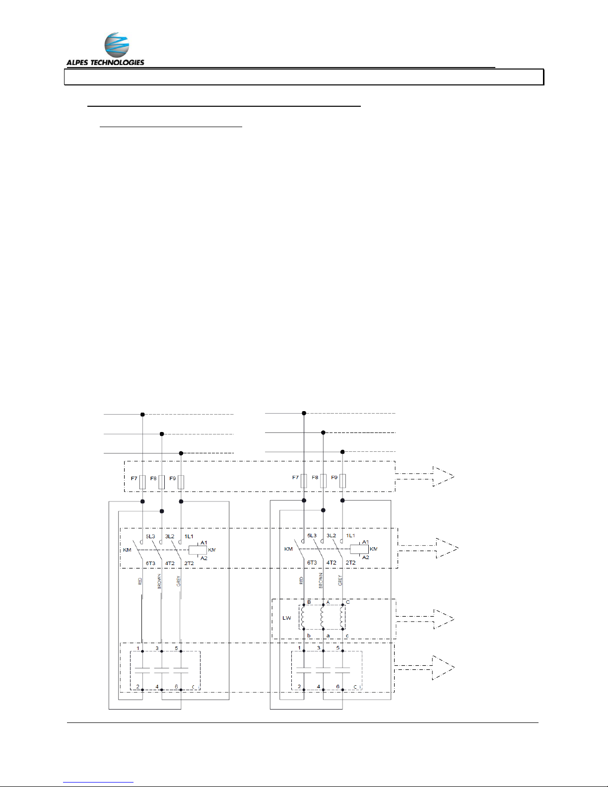
C – CIRCUITS AUXILIAIRES
Le bon fonctionnement de votre batterie est assuré avec le branchement des équipements
suivants :
Transformateur de courant T.C.
Délestage du groupe électrogène
(1)
Kit sécurité
(2)(3)
Les équipements annexes se raccordent sur un ensemble borniers :
Kit sécurité
Groupe électrogène
Transformateur de
courant
Caractéristiques
Contact NF
Puissance : 600VA
maxi
Borne pour contact de
délestage
Consommation : 10,5 W
Entrée courant : 1A ou 5A
Puissance : 10 VA mini
Classe 1
Section des
câbles
2,5 mm²
2,5 mm²
2,5 mm² à 6 mm²
Bornes
X1/X2
G/E
S1/S2
(1)
Dans le cas ou un groupe électrogène est présent sur le réseau interne
(2)
Non inclus dans les armoires sans selfs de hauteur 770mm, en version avec disjoncteur avec une puissance ≤ 125Kvar,
en version sans disjoncteur avec une puissance ≤ 150 Kvar.
(3)
Veuillez vous reporter à la page 12 pour plus d’informations.
Page 18
_____________________________________________________________________________________________________
17
Veillez à garder le cavalier en cas de maintenance ou changement de régulateur pour
réaliser le court-circuit des bornes auxiliaires S1/S2. Vous pouvez vous procurer des
cavaliers supplémentaires en référence : 037508 sur le catalogue Legrand.
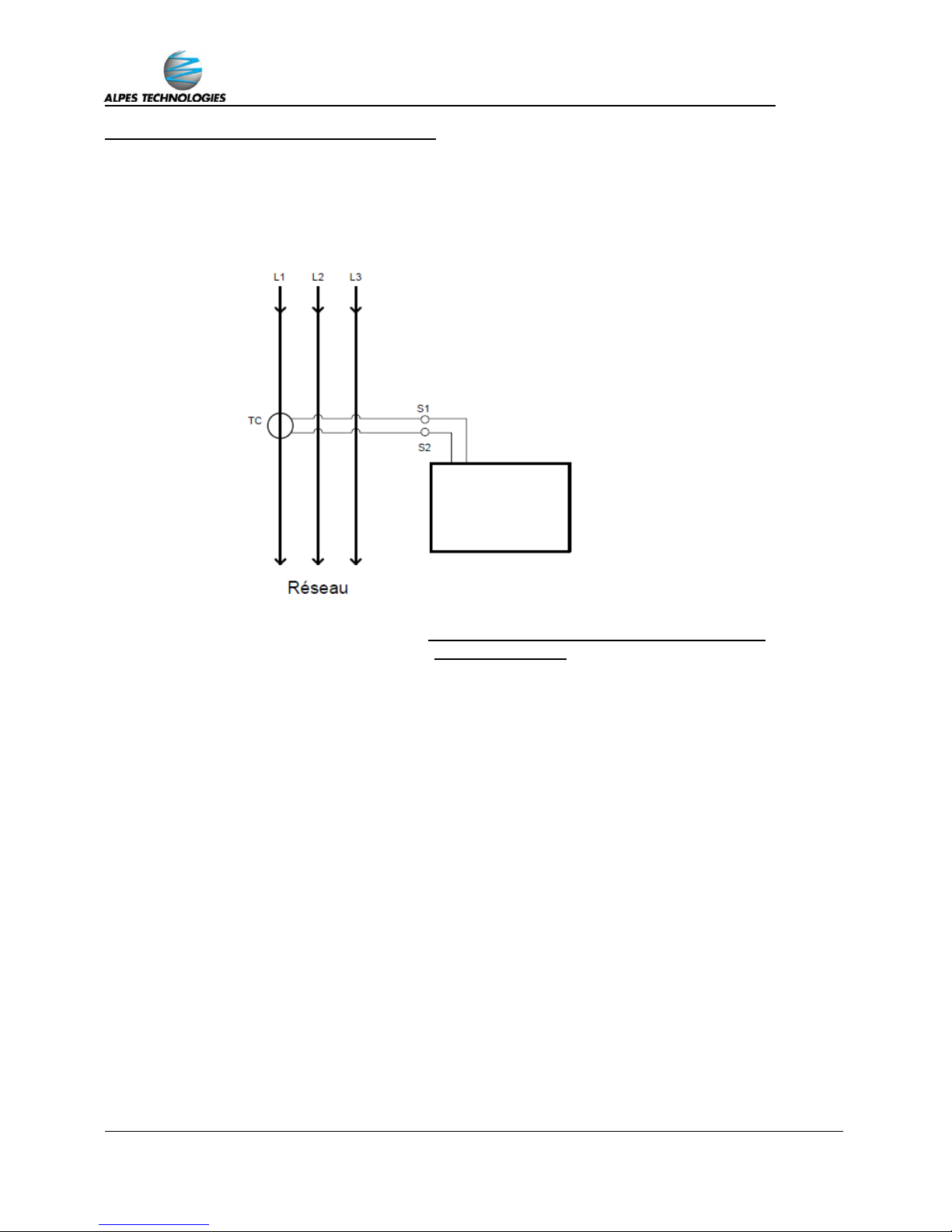
I – Raccordement du transformateur de courant T.C. :
Le T.C. est à positionner sur la phase L1 de l’installation à compenser, en amont de tous les
récepteurs à compenser et de la batterie de condensateurs.
Le branchement s’effectue de la façon suivante :
Les bornes S1 & S2 sont livrées court-circuitées par un cavalier.
Connectez sur les bornes les câbles du T.C., puis enlevez le cavalier pour assurer
le fonctionnement du régulateur par le biais du T.C.
En cas d’intervention ou maintenance sur le T.C., veuillez reprendre les étapes dans le
sens inverse.
Le T.C. peut se positionner de 3 façons différentes selon le type d’installation :
Installation avec un transformateur :
ALPTEC
Page 19
_____________________________________________________________________________________________________
18
FR
Installation avec deux transformateurs :
Vous devez prévoir sur cette installation :
o 1 T.C. sur la phase L1 de chaque transformateur
o 1 T.C. général sommateur 5+5…/5A
La valeur du primaire à programmer dans le régulateur sera la somme
des primaires de chaque transformateur
Installation avec deux transformateurs et système de couplage :
Vous devez prévoir sur cette installation:
o 1 T.C. sur la phase L1 principale de chaque transformateur
o 1 T.C. sur la phase L1 de regroupement pour chaque transformateur
o 1 T.C. général sommateur 5+5…/5A pour chaque transformateur
La valeur du primaire à programmer dans le régulateur sera la valeur du
primaire du transformateur auquel il est raccordé
ALPTEC
ALPTEC 1
ALPTEC 2
Page 20
_____________________________________________________________________________________________________
19
Veillez à garder le cavalier en cas de maintenance pour réaliser le court-circuit des
bornes auxiliaires G/E. Vous pouvez vous procurer des cavaliers supplémentaires en
référence : 037508 sur le catalogue Legrand.
II – Fonctionnement sur groupe électrogène :
En cas de coupure du réseau de distribution électrique, l’alimentation de l’installation peut être
assurée par l’intermédiaire d’un groupe électrogène. Lors de son fonctionnement, il est impératif
que la batterie de condensateurs se déconnecte automatiquement.
Pour cela il faut raccorder le groupe électrogène au niveau du bornier
des auxiliaires
(1)
.
Le branchement s’effectue de la façon suivante :
Les bornes G & E sont court-circuitées par un cavalier qu’il faut retirer
en premier.
Connectez sur les bornes un contact à ouverture pour le fonctionnement du
groupe électrogène.
Au démarrage du groupe électrogène, la batterie de condensateurs sera
automatiquement déconnectée.
En cas d’intervention ou maintenance sur le groupe électrogène, veuillez
reprendre les étapes dans le sens inverse.
(1)
Voir le paragraphe raccordement des auxiliaires page 16
Page 21
_____________________________________________________________________________________________________
20
Avant la premiére mise sous tension :
Vérifier les caractéristiques techniques du local d’installation en page 11.
Vérifier les réglages des protections et le raccordement des câbles de
puissance.
Effectuer le resserrage des connexions de puissance interne.
Vérifier le positionnement du T.C. en pages 14 et 15.
Tout manquement à la stricte application des procédures et avertissements peut
induire à une défaillance prématurée, explosion, ou départ de feu de l’équipement.
FR
4 – MISE SOUS TENSION
A – 1ere MISE SOUS TENSION
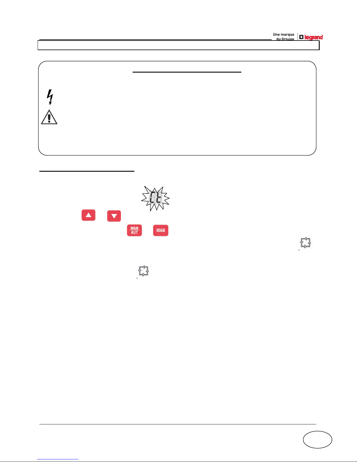
Si la batterie de condensateurs est livrée sans T.C. :
1 / L’écran principal affiche le code
1 / Utilisez ou pour modifier la valeur du primaire.
2 / Validez en appuyant sur ou .
Le régulateur sauvegarde la valeur du paramètre est se lance en mode .
Si la batterie de condensateurs est livrée, sur demande, avec son T.C. :
1 / la batterie démarre en mode .
Vous n’avez à apporter aucune modification.
Page 22
_____________________________________________________________________________________________________
21
B - CONTROLE DE LA POSITION DU TC
En cas de mauvaise lecture du cos φ par le régulateur il est nécessaire de contrôler la position
du T.C.
(1)
:
1 / Vérifiez que celui-ci soit bien positionné sur la phase L1 en amont de toutes les charges à
compenser.
2 / A l’aide d’un voltmètre vérifiez que la tension est nulle entre la phase L1 réseau sur
laquelle vous avez installé le T.C. et la phase L1 batterie.
(1)
Se reporter aux pages 17 et 18 pour plus d’informations
ALPTEC
Page 23
_____________________________________________________________________________________________________
22
FR
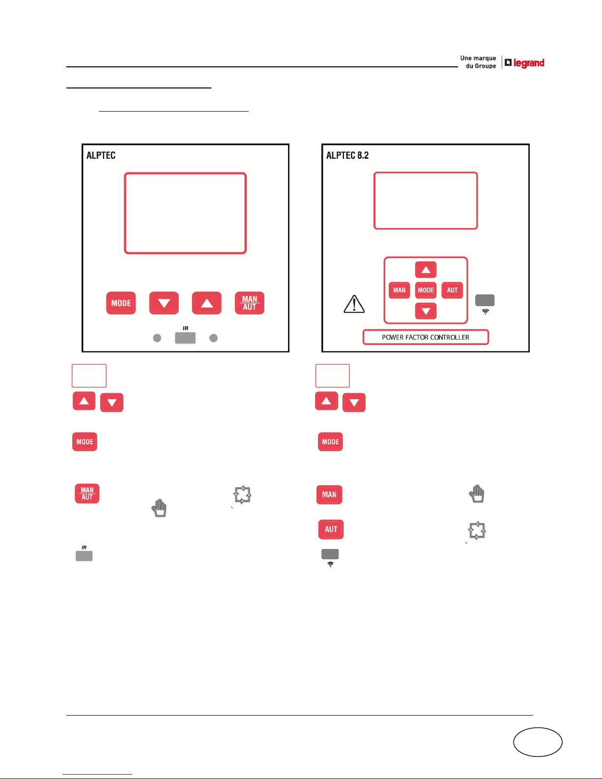
C – REGULATEUR ALPTEC
I – Présentation des régulateurs :
ALPTEC 3.2/5.2 ALPTEC 8.2
- : Ecran à affichage LCD retro-éclairé - : Ecran à affichage LCD retro-éclairé
- : Réglage des valeurs et sélection - : Réglage des valeurs et sélection
des gradins. des gradins.
- : sélection des mesures disponibles, - : sélection des mesures disponibles,
accès aux menus de programmations accès aux menus de programmations
et verrouillage clavier
(1)
. et verrouillage clavier
(1)
.
- : passage entre mode “AUT” - : Passage en mode “MAN”
et “MAN” .
- : passage en mode “AUT”
- : Port optique à haute vitesse, compatible - : Port optique à haute vitesse, compatible
USB et Wi-Fi. USB et Wi-Fi.
(1)
Se reporter à la notice du régulateur pour plus d’informations.
Page 24
_____________________________________________________________________________________________________
23
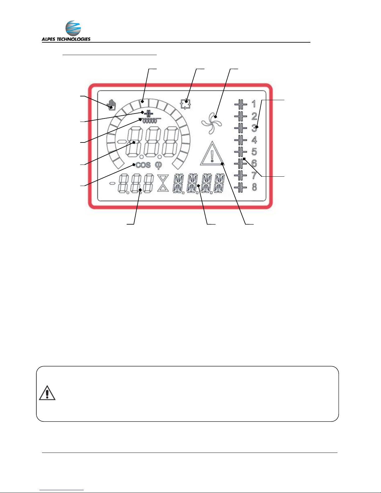
II – Descriptif de l’afficheur LCD :
1 : Nombre de gradins installés dans la batterie
2 : Etat des gradins (enclenché/non-enclenché)
3 : Etat de l’alarme (non-active/active)
4 : Zone alphanumérique (unités, menus, codes alarmes)
5 : Zone numérique (indications des valeurs)
6 : Affichage du cos φ (actif/non actif)
7 : Zone d’affichage principale (cos φ, menu principal, codes paramètres)
8 : Mode inductif
9 : Mode capacitif
10 : Mode manuel
11 : Barre graphique configurable (par défaut : % de la puissance enclenchée)
12 : Mode automatique
13 : Fonctionnement des ventilateurs (marche/arrêt)
Pour tout autre réglage (cos φ) ou manipulation (mode manuel, verrouillage
clavier), veuillez vous rapporter à la notice d’utilisation du régulateur.
13
12
11
10
Toute modification des paramètres du régulateur en mode avancé (excepté les
paramètres du primaire T.C. et cos φ) comporte le risque d’usure prématurée voire de
destruction de l’équipement, comportant les risques sur son environnement et sur les
personnes, et la non disponibilité de l'installation, et se fera sous l’entière et stricte
responsabilité de l’utilisateur. Le groupe Legrand décline toute responsabilité et toute
garantie.
1 2 3 4 5 6 7 8 9
Page 25
_____________________________________________________________________________________________________
24
FR
III – Mesures :
Le régulateur ALPTEC fournit un ensemble de mesures sur l’écran alphanumérique, en liaison
avec le cos phi qui est toujours affiché sur l’écran principal.
La touche permet d’accéder à différentes mesures dont vous pouvez trouver le détail ci-
dessous :
Mesure
Icône
Description
Delta-kvar
∆kvar
kVAr nécessaire pour atteindre le cos phi de consigne. Si >0 des
gradins seront enclenchés, si <0 ils seront déconnectés.
kvar
kVAr total de l’installation.
∆STEP
Nombres de gradins équivalents.
Tension
V
Tension RMS de l’installation.
V HI
Valeur maximale de la tension.
Courant
A
Courant RMS de l’installation.
A HI
Valeur maximale de l’installation.
Cosphi hebdo
WPF
Cos phi hebdomadaire moyen.
PF
Cos phi instantané.
Courant condo
%C.CU
Calcul du courant condensateur, en % de leur valeur nominale.
%C.HI
Valeur maximale de la mesure.
Température
°C °F
Température.
°CHI
°FHI
Valeur maximale de la température.
THD Tension
THDV
Distortion harmonique totale tension % (THD) de l’installation.
VH02...
...VH15
Harmonique de tension individuelle, %, du rang 2 au rang 15.
THD Courant
THDI
Distortion harmonique totale courant % (THD) de l’installation.
IH02...
...IH15
Harmonique de courant individuelle, %, du rang 2 au rang 15
Cosphi
Consigne
IND
CAP
Réglage du cos phi de consigne.
Page 26
_____________________________________________________________________________________________________
25
Pour toutes résolutions de problèmes, veuillez vous rapporter au guide de
maintenance
5 – MAINTENANCE
Durant son utilisation, votre batterie de condensateurs automatique peut être exposée à
différents facteurs tels que les harmoniques, une température élevée, des surtensions, une évolution de
l’installation, la pollution ambiante (poussières, vapeurs), usure de fonctionnement (contacteur,
condensateur), etc.
Ces facteurs sont susceptibles d’avoir des conséquences néfastes sur la batterie de
compensation automatique et de réduire la durée de vie de cette dernière.
Il est donc important de réaliser les opérations de maintenances selon les préconisations du plan
de maintenance annuel de votre guide de maintenance, et ainsi prolonger la durée de vie de votre
batterie de compensation.
Pour réaliser une maintenance préventive et curative de qualité de votre batterie de
condensateurs, vous pouvez compter sur notre réseau commercial d’experts en contactant votre
interlocuteur du groupe Legrand qui vous apportera la meilleure solution adaptée à votre besoin.
Page 27

_____________________________________________________________________________________________________
26
EN
ALPIMATIC/BX AUTOMATIC
CAPACITOR BANKS
Installation Guide
Page 28

_____________________________________________________________________________________________________
27
Page 29

_____________________________________________________________________________________________________
28
EN
CONTENTS
1 – Safety instructions ............................................................................... 29
2 – Technical characteristics
A – Automatic capacitor bank
I – General characteristics ....................................................... 31
II – Enclosure ........................................................................... 32
III – Capacitors .......................................................................... 32
IV – Ranges ............................................................................... 32
B – Installation site characteristics ..................................................... 33
C – Safety kit ....................................................................................... 34
3 – Connection
A – Protection .................................................................................... 35
B – Power circuit ................................................................................ 35
C – Auxiliary circuits
I – Connecting the current transformer (CT) ........................... 38
II – Generator operation .......................................................... 41
4 – Switch-on
A – 1st switch-on ................................................................................ 42
B – Checking the CT position .............................................................. 43
C – ALPTEC controller
I – Overview of controllers ..................................................... 44
II – Description of the LCD display ........................................... 45
III – Measures ........................................................................... 45
5 – Maintenance .......................................................................................... 47
Page 30
_____________________________________________________________________________________________________
29
1 – SAFETY INSTRUCTIONS
General
The automatic capacitor banks must be installed in accordance with the installation instructions
described in the manuals. If they have suffered any external knocks or blows, do not connect or use
the capacitors or capacitor banks.
Incorrect installation and use may lead to the risk of electric shock or fire. Capacitor banks must be
used in normal conditions, in other words they must not be subjected to any other
Voltage/Current/Frequency/Harmonic distortion/Temperature values than those specified in the sales
catalogue and manual.
Only use accessories recommended by the Legrand Group in the sales catalogue and manuals.
As we are keen to ensure the highest levels of performance of our products, they may be subject to
modification. Please check the accuracy of the product specifications during installation and
commissioning operations, and refer to the relevant manuals. If you have any questions or need any
clarification, please contact your Legrand Group representative.
Installation, use and maintenance of an automatic capacitor bank must only be undertaken by trained
and authorised staff, in accordance with the regulations in force specific to each country.
Any modification of the automatic capacitor banks which has not previously been authorised
by the Legrand Group voids all liability, replacement rights and warranties.
Risks of electric shocks, burns and explosion
Wear the necessary PPE (personal protective equipment) when working on live products.
Comply with the safety procedures associated with electrical work.
Inappropriate electrical and mechanical use of equipment can be dangerous and can result in
physical injury or material damage.
Ensure that the automatic capacitor banks are correctly earthed.
Switch off all the capacitor bank power supplies before working on it.
Before working on live parts, wait at least 5 minutes for the capacitors to discharge, then short-circuit
the terminals and earth the capacitor.
During operations involving access inside the capacitor bank, beware the risk of burns when touching
the products or metal parts (during operation or just after the capacitor bank has been switched off).
Before restoring power to the capacitor bank, check that all the physical protection devices have
been replaced (for example: shield, cover, door).
Any failure to follow procedures and warnings to the letter can lead to premature failure,
explosion, or an outbreak of fire in the equipment.
Page 31

_____________________________________________________________________________________________________
30
EN
Warranty limits/Responsibilities
The points listed below apply to all products mentioned in this publication and all other Legrand Group
technical sales material:
The recommendations in this publication are based on our knowledge of the typical conditions of use
for our products in the application areas usually encountered. However, it is always incumbent on
customers to check and confirm that Legrand products (with the technical specifications described)
are suitable for their installation.
For applications which require a very high level of safety (e.g. where failure of a component might
endanger the life or health of personnel), customers need to ensure good practice is followed in
installation, maintenance and use of the equipment to prevent any risk of injury to personnel or
damage to equipment if the product fails.
The rules for storage, handling, installation and maintenance, as well as appropriate precautions and
warnings, must be observed and applied.
Page 32

_____________________________________________________________________________________________________
31
2 – TECHNICAL CHARACTERISTICS
A – CAPACITOR BANK:
I – General characteristics:
Identification label:
o No. (manufacturing batch + product reference)
o Power (kVAr)
o Voltage (V)
o Current (A)
o Frequency (Hz)
o Phases
o Insulation (kV)
o Step power rating
o Ref. (finished product reference)
See the label inside the enclosure for the detailed values.
Loss factor: 2 W/kVAr (without reactor), 6 W/kVAr (with reactor)
Enclosure maximum internal temperature: +45°C
Enclosure average internal temperature over 24 hrs: 40°C
Conformity with standards: IEC 61439- 2 and IEC 61921
Details of steps:
Simple capacitors Capacitors with detuned reactor
Protection
fuses
Capacitor with
control auxiliary
Detuned
reactor
Capacitor
Page 33

_____________________________________________________________________________________________________
32
EN
II – Enclosure:
Casing:
o Protection index: IP 30
o Mechanical impact resistance: IK 10
o Enclosure colour: RAL 7035 + black base
(1)
Generator set contact terminal blocks: YES
(2)
CT secondary connection contact terminal blocks: YES
(2)
Contact terminal blocks + smoke detector safety kit: YES
(2)(3)
III – ALPIVAR capacitors:
Capacitance tolerance: ± 5%
Permissible overvoltage: 1.18 x Un (12/24 hrs)
Conformity with standards: IEC 60831-1/2
Loss factor: 0.3 W/kVAr (this consumption value includes the discharge resistors)
IV – Ranges:
Type
THDu (%)
THDi (%)
SH/ST (%)
S
≤ 3
≤ 10
≤ 15
H
≤ 4
≤ 15
≤ 25
SAH
(4)
≤ 6
≤ 30
≤ 35
Reinforced SAH
(4)
≤ 8
≤ 40
≤ 50
Extra-reinforced
SAH
(4)
≤ 11
(5)
≤ 55
(5)
≤ 65
(5)
THDu: voltage total harmonic distortion
THDi: current total harmonic distortion
SH: expanded power of the harmonic generators in the secondary of the MV/LV
transformer to be compensated (in kVA)
ST: transformer power (in kVA)
(1)
Except on enclosures with power ≤ 125 kVAr.
(2)
See connection/auxiliary circuits section on page 38 for more information.
(3)
Not included in 770 mm high enclosures without reactors, in version with circuit breaker with power ≤ 125 kVAr, in version
without circuit breaker with power ≤ 150 kVAr.
(4)
Enclosure with detuned reactor, check the frequency is compatible with your electricity supplier. For other frequencies, please
consult your Legrand Group representative.
(5)
Above this harmonic level, please contact your Legrand Group representative who can do an audit of the installation and offer
you a bespoke solution to meet your requirements (compensation, harmonic processing).
Page 34

_____________________________________________________________________________________________________
33
B – INSTALLATION SITE CHARACTERISTICS
Following the recommendations below will ensure the capacitor bank works correctly:
Min./max. temperature: -5°C to +40°C
Average temperature over 24 hrs: +35°C
Max. altitude ≤ 2000 m
Environment:
o Maximum humidity rate ≤ 80%
o Free of dust
o No corrosive products present
Ventilation:
o 200 mm minimum space must be left around the ventilation louvres
(wall, ceiling, other elements)
o The air intakes and outlets must not be blocked
o Ventilation of the capacitor bank is provided by the flow of air:
Air intake via the bottom, as the ventilation louvres are located on the
front and back as well as on the sides.
Outlet via the top:
Banks without detuned reactors natural extraction
through the louvres on the front and back as well as on
the sides.
Banks with detuned reactors forced extraction
(1)
through the fans located on the enclosure roof.
(1)
Natural extraction for SAH type enclosures with power ≤ 150 kVAr.
Any failure to follow procedures and warnings to the letter can lead to premature
failure, explosion, or an outbreak of fire in the equipment, and will automatically
invalidate the enclosure warranty.
Page 35

_____________________________________________________________________________________________________
34
The following operations must be undertaken to ensure the detector kit works
correctly:
Perform annual maintenance (cleaning, tightening) on the safety kit.
Conduct an annual check of the smoke detectors.
Change the smoke detector as often as recommended in the maintenance guide.
Any failure to follow procedures and warnings to the letter can lead to premature
failure, explosion, or an outbreak of fire in the equipment, and will automatically
invalidate the enclosure warranty.
Beware, the capacitor bank can be under voltage even if the controller is switched off
EN
C – SAFETY KIT
Capacitor banks are equipped as standard with a safety kit
(1)
:
Each cubicle is equipped with its own smoke detector.
If smoke is detected by the safety kit:
o “ALPTEC” controller power supply switched off.
o The contactors switch to the “open” position.
o Buzzer
(2)
on the front of the enclosure activated with transmission of an
audible and visual signal.
o An NC contact marked “X1/X2” opens to enable remote signalling.
This signalling must always be done by the customer.
o Fan
(3)
switched off.
The fault is maintained until the capacitor bank
(4)
is switched off.
(1)
Not included in 770 mm high enclosures without reactors, in version with circuit breaker with power ≤ 125 kVAr, in version
without circuit breaker with power ≤ 150 kVAr.
(2)
Legrand Cat. No. 041525.
(3)
For enclosures with forced ventilation.
(4)
Please contact your Legrand Group representative to request diagnostics on your affected capacitor bank enclosure.
Page 36

_____________________________________________________________________________________________________
35
3 – CONNECTION
A – PROTECTION
Capacitor banks not equipped as standard with a general protection system must always be
fitted with one. It should be installed at the start of the power supply cable with:
A circuit breaker:
o with a thermal relay
(1)
set to 1.4 x In minimum
o with a magnetic relay
(1)
set to between 8 and 10 x In
A gG type HPC switch-fuse, with a rating of 1.4 x In minimum
B – POWER CIRCUIT
The recommendations below must be followed when connecting capacitor banks to the main
power supply:
The power cables used for connection must have minimum dimensions of:
I = 1.43 x In
(2)
The cross-section calculation must take account of the usual coefficients associated with
the cable type:
o Type
o Length
o Installation method
Phases L1/L2/L3 must be connected as marked on the internal busbar.
For enclosures made up of several cubicles, the busbar in each cubicle MUST be
connected to the upstream power supply via power cables of the same quantities
and cross-sections in order to ensure balanced distribution of the currents
(1)(3)
.
The capacitor bank must be earthed with a cable whose cross-section complies with the
current standard.
(1)
To help you choose, you can consult the table on page 36.
(2)
See the table of recommended cross-sections for the power supply cables on page 36.
(3)
Except on versions with built-in general protection system.
Page 37

_____________________________________________________________________________________________________
36
EN
Recommended power supply cable cross-sections
(1)
:
Power
400 V
(kVAr)
In
(A)
Supply end
protection
(2)
Rating
In (A)
Thermal
setting
Ir (A)
Single
enclosure
x-section
(mm²)
Double
enclosure
x-section
(mm²)
Triple
enclosure
x-section
(mm²)
10
14
DPX3 160
25
20 4 - - 15
22
DPX3 160
40
32 6 - - 20
29
DPX3 160
40
40
10 - -
25
36
DPX3 160
63
50
16 - -
30
43
DPX3 160
63
63
16 - -
35
51
DPX3 160
80
80
25 - -
40
58
DPX3 160
80
80
25 - -
47.5
69
DPX3 160
100
100
35 - -
50
72
DPX3 160
100
100
35 - -
60
87
DPX3 160
125
125
50 - -
67.5
97
DPX3 160
160
128
50 - -
75
108
DPX3 160
160
160
70 - -
80
115
DPX3 160
160
160
70 - -
87.5
126
DPX3 250
200
180
95 - -
100
144
DPX3 250
200
200
95 - -
112.5
162
DPX3 250
250
225
150 - -
125
180
DPX3 250
250
250
150 - -
150
217
DPX3 630
400
300
185 - -
175
253
DPX3 630
400
350
240 - -
200
289
DPX3 630
400
400
300 - -
225
325
DPX3 630
630
441
400 - -
250
361
DPX3 630
630
504
400 - -
275
397
DPX3 630
630
567
500 - -
300
433
DPX3 630
630
599
630
2x(1x240)
-
325
469
DPX3 630
630
630
630
2x(1x300)
-
350
505
DPX3 1600
800
720
2x400
2x(1x400)
-
375
541
DPX3 1600
800
760
2x400
2x(1x400)
-
400
577
DPX3 1600
800
800
2x400
2x(1x400)
-
450
650
DPX3 1600
1000
900
2x500
2x(1x500)
-
500
722
DPX3 1600
1000
1000
2x630
2x(1x630)
-
550
794
DPX3 1600
1250
1063
2x630
2x(1x630)
-
600
866
DPX3 1600
1250
1188
3x500
2x(2x400)
3x(1x500)
650
938
DPX3 1600
1250
1250
3x500
2x(2x400)
3x(1x500)
675
974
DPX3 1600
1600
1360
3x630
2x(2x500)
3x(1x630)
700
1010
DPX3 1600
1600
1440
3x630
2x(2x500)
3x(1x630)
750
1083
DPX3 1600
1600
1520
4x500
2x(2x500)
3x(2x400)
800
1155
DPX3 1600
1600
1600
4x630
2x(2x630)
3x(2x400)
850
1227
DMX
3
2000
1700
4x630
2x(2x630)
3x(2x400)
900
1299
DMX
3
2000
1800
4x630
2x(2x630)
3x(2x500)
950
1371
DMX
3
2000
1900
5x630
2x(3x500)
3x(2x500)
1000
1443
DMX
3
2000
2000
5x630
2x(3x500)
3x(2x500)
(1)
Indicative values based on the following elements:
* IEC 61439-1 and 60364-5-52
* calculation for copper conductors / cables grouped and enclosed with a permissible temperature of 70 ° C and an ambient
temperature around 55 ° C cables
* the length of the cables is not taken into account
(2)
For power supply cross-sections, enclosures equipped with supply end protection are equivalent to a single enclosure, even if the
enclosure is double or triple.
Page 38

_____________________________________________________________________________________________________
37
For checking of tightening torques according to the maintenance schedule, please
refer to the maintenance guide.
Apply the correct tightening torque according to the equipment used to connect the power
circuit to the capacitor bank .
Tightening torque of the power circuit/capacitor bank connection
Type
Max. tightening torque
Power supply with circuit breakers
DPX3 160
8 N.m
(1)
7 N.m
DPX3 250
10 N.m
DPX3 630
24 N.m
DPX3 1600
14 N.m (x2 screws)
Power supply without circuit breaker
Busbar
15 N.m
Measurement accessory
CT
1 N.m
Viking terminal block
0.8 N.m (for a 2.5 mm² cross-section)
1.4 N.m (for a 6 mm² cross-section)
Check visually, looking at the varnish on the screw heads, that none of them
have come loose.
Check the contactor terminal tightening torque
(4)(5)
.
(1)
If using a cage terminal.
Any failure to follow procedures and warnings to the letter can lead to premature
failure, explosion, or an outbreak of fire in the equipment, and will automatically
invalidate the enclosure warranty.
Page 39

_____________________________________________________________________________________________________
38
EN
C – AUXILIARY CIRCUITS
Your capacitor bank is guaranteed to work if the following equipment is connected:
Current transformer (CT)
Generator load shedding
(1)
Safety kit
(2)(3)
The ancillary equipment is connected to a set of terminal blocks:
Safety kit
Generator set
Current transformer
Characteristics
NC contact
Power: 600 VA max.
Terminal for load-
shedding contact
Consumption: 10.5 W
Current input: 1 A or 5 A
Power: 10 VA min.
Class 1
Cable cross-
section
2.5 mm²
2.5 mm²
2.5 mm² to 6 mm²
Terminals
X1/X2
G/E
S1/S2
(1)
When there is a generator on the internal supply.
(2)
Not included in 770 mm high enclosures without reactors, in version with circuit breaker with power ≤ 125 kVAr, in version
without circuit breaker with power ≤ 150 kVAr.
(3)
Please refer to page 31 for more information.
Page 40

_____________________________________________________________________________________________________
39
Make sure you keep the jumper for controller maintenance or replacement operations
so you can short-circuit the S1/S2 auxiliary terminals. Extra jumpers can be obtained
quoting Cat. No. 037508 from the Legrand catalogue.
I – Connecting the current transformer (CT):
The CT should be positioned on phase L1 of the installation to be compensated, upstream of all
the receivers to be compensated and the capacitor bank.
It is connected as follows:
Terminals S1 & S2 are supplied short-circuited by a jumper.
Connect the CT cable terminals, then remove the jumper so the controller works via
the CT.
If work or maintenance is being carried out on the CT, repeat these steps in reverse
order.
The CT can be positioned in 3 different ways depending on the type of installation:
Installation with one transformer:
ALPTEC
CT CT
CT
Page 41

_____________________________________________________________________________________________________
40
EN
Installation with two transformers:
This installation requires:
o 1 CT on phase L1 of each transformer
o 1 general summation CT 5+5…/5 A
The value of the primary to be programmed in the controller should be the
sum of the primaries of each transformer
Installation with two transformers and coupling system:
This installation requires:
o 1 CT on the main phase L1 of each transformer
o 1 CT on the group phase L1 for each transformer
o 1 general summation CT 5+5…/5 A for each transformer
The value of the primary to be programmed in the controller should be the
value of the primary for the transformer to which it is connected
ALPTEC
CT 1
CT 2
Page 42

_____________________________________________________________________________________________________
41
Make sure you keep the jumper for maintenance operations so you can short-circuit
the G/E auxiliary terminals. Extra jumpers can be obtained quoting Cat. No. 037508
from the Legrand catalogue.
II – Generator operation:
In the event of failure of the electrical distribution system, the installation can be supplied with
power by a generator. During generator operation, the capacitor bank must disconnect itself
automatically.
For this to happen, the generator needs to be connected to the terminal
block for the auxiliaries
(1)
.
It is connected as follows:
Terminals G & E are short-circuited by a jumper which needs to be removed
prior to connection.
Connect an NC contact to the terminals in order for the generator to work.
When the generator starts, the capacitor bank will be disconnected
automatically.
If work or maintenance is being carried out on the generator, repeat these
steps in reverse order.
(1)
See the section on connecting the auxiliaries on page 38.
Page 43

_____________________________________________________________________________________________________
42
EN
Before 1st switch on :
Check the technical characteristics of the installation site on page 33.
Check the power cable protection and connection settings
Tighten the internal power connections.
Check the CT positioning on pages 39 and 40.
Any failure to follow procedures and warnings to the letter can lead to premature
failure, explosion, or an outbreak of fire in the equipment.
4 – SWITCH-ON
A – 1ST SWITCH-ON
If the capacitor bank is supplied without a CT:
1 / The main screen displays the code
1 / Use or to change the value of the primary.
2 / Confirm by pressing or .
The controller saves the parameter value and starts up in mode.
If the capacitor bank is supplied, on request, with its own CT:
1 / The capacitor bank starts in mode.
You don’t need to change anything.
Page 44

_____________________________________________________________________________________________________
43
C – CHECKING THE CT POSITION
If the controller reads the cos φ incorrectly, you need to monitor the CT position.
(1)
:
1 / Check it is positioned correctly on phase L1 upstream of all the loads to be compensated.
2 / Using a voltmeter, check that the voltage is zero between the mains phase L1 on which
you have installed the CT and the capacitor bank phase L1.
(1)
Refer to pages 39 and 40 for more information.
ALPTEC
CT
Page 45

_____________________________________________________________________________________________________
44
EN
D – CONTROLLER
I – Overview of controllers:
ALPTEC 3.2/5.2 ALPTEC 8.2
-
: Backlit screen with LCD display
-
: Backlit screen with LCD display
-
: Set the values and select
the steps.
-
: Set the values and select
the steps.
-
: Selection of available measurements,
access to the programming and
keyboard lock menus
(1)
.
-
: Selection of available measurements,
access to the programming and
keyboard lock menus
(1)
.
-
: Switch between “AUT” mode
and “MAN” mode
-
: Switch to “MAN” mode
-
: Switch to “AUT” mode
-
: High-speed optical port,
USB and Wi-Fi compatible.
-
: High-speed optical port,
USB and Wi-Fi compatible.
(1)
Refer to the controller manual for more information.
Page 46

_____________________________________________________________________________________________________
45
II – Description of the LCD display:
1: Number of steps installed in the capacitor bank
2: Step status (activated/non-activated)
3: Alarm status (inactive/active)
4: Alphanumeric area (units, menus, alarm codes)
5: Numeric area (indications of values)
6: Cos φ display (active/inactive)
7: Main display area (cos φ, main menu, parameter codes)
8: Leading mode
9: Trailing mode
10: Manual mode
11: Configurable bar graph (by default: % of the power activated)
12: Automatic mode
13: Fan operation (on/off)
For all other settings (cos φ) or manipulations (manual mode, keyboard lock),
please refer to the controller manual.
13
12
11
Any modification of the controller advanced mode parameters (except for the primary CT
and cos φ parameters) carries the risk of premature wear or even destruction of the
equipment, involving risks to its environment and people, leading to unavailability of the
installation, and the user is wholly responsible for any such action. The Legrand Group
accepts no liability and the warranty is rendered null and void.
10
1 2 3 4 5 6 7 8 9
Page 47

_____________________________________________________________________________________________________
46
EN
III – Measures :
The ALPTEC controller provides a set of measurements on the alphanumeric display, in
conjunction with the cos phi which is always displayed on the main screen.
The key allows access to different measures which you can find the detail below :
Measure
Icon
Description
Delta-kvar
∆kvar
kVAr needed to reach the cosphi setpoint. If delta-kvar is positive
cpacitors need to be inserted, if negative to be disconnected.
kvar
Total kVAr of the plant.
∆STEP
Number of equivalent steps.
Voltage
V
RMS voltage of the plant current.
V HI
Maximum peak of measure.
Current
A
RMS current of the plant voltage.
A HI
Maximum peak of measure.
Week PF
WPF
Weekly average power factor.
PF
Instantaneous total power factor.
Capacitor
Curr.
%C.CU
Calculated capacitor current, in % of their nominal.
%C.HI
Maximum peak of measure.
Temperature
°C °F
Temperature of internal sensor.
°CHI
°FHI
Maximum peak of measure.
THD Voltage
THDV
Total harmonic distortion % (THD) of plant voltage.
VH02...
...VH15
% voltage harmonic content from 2.nd up to 15.th orde.r
THD Current
THDI
Total harmonic distortion % (THD) of plant current.
IH02...
...IH15
% current harmonic content from 2.nd up to 15.th order.
Set Cosphi
IND
CAP
Setting of desired cosphi setpoint.
Page 48

_____________________________________________________________________________________________________
47
For all problem solving, please refer to the maintenance guide.
6 – MAINTENANCE
During use, your automatic capacitor bank may be exposed to different factors such as
harmonics, high temperatures, voltage surges, an installation upgrade, environmental pollution (dust,
vapours), and wear and tear (contactor, capacitor), etc.
These factors are likely to have harmful consequences on the automatic capacitor bank and
therefore to reduce its service life.
It is therefore important to carry out maintenance operations as outlined in the annual
maintenance schedule in the maintenance guide, thereby extending the service life of your capacitor
bank.
If you would like high-quality preventive and remedial maintenance to be performed on your
capacitor bank, our network of expert sales advisers is ready to help. Please contact your usual Legrand
Group representative who will offer you the optimum solution to meet your needs.
Page 49

________________________________________________________________________________
48
ESP
BATERÍAS DE CONDENSADORES
AUTOMÁTICOS ALIMATIC/BX
Guía de instalación
Page 50

________________________________________________________________________________
49
Page 51

_____________________________________________________________________________________________________
50
ESP
CONTENIDO
1. Información de seguridad ............................................................................. 51
2. Características técnicas
A. Batería de condensadores automático
I. Características generales .............................................................. 53
II. Armario ........................................................................................ 54
III. Condensadores ALPIVAR/BX ......................................................... 54
IV. Gamas .......................................................................................... 54
B. Características del local de instalación .................................................... 55
C. Kit de seguridad ...................................................................................... 56
3. Conexión
A. Protección ............................................................................................... 57
B. Circuito de alimentación ......................................................................... 57
C. Circuitos auxiliares
I. Conexión del transformador de corriente T.C ............................... 61
II. Funcionamiento en grupo electrógeno ......................................... 63
4. Conexión a la corriente eléctrica
A. Conexión a la corriente eléctrica por primera vez ................................... 64
B. Control de la posición del T.C .................................................................. 65
C. Regulador ALPTEC
I. Presentación de reguladores ......................................................... 66
II. Descripción de la pantalla LCD ..................................................... 67
III. Pasos ........................................................................................... 68
5. Mantenimiento ................................................................................................ 69
Page 52

________________________________________________________________________________
51
1. INFORMACIÓN DE SEGURIDAD
Aspectos generales
Las baterías de condensadores automáticas deben instalarse de conformidad con las normas de
instalación recogidas en las instrucciones. En el supuesto de que se produzca una descarga
externa, no utilice ni conecte los condensadores ni sus baterías.
Una instalación y un uso incorrectos pueden provocar descargas eléctricas o incendios. Las baterías
de condensadores deben utilizarse en condiciones normales, esto es, no deben someterse a valores
de tensión/corriente/frecuencia/tasa armónica/termperaturas distintos a los especificados en las
instrucciones y el catálogo comercial.
Utilice exclusivamente los accesorios recomendados por Legrand en las instrucciones y el catálogo
comercial.
Nos comprometemos a garantizar el mejor rendimiento posible de nuestros productos en todo
momento, por lo que pueden estar sujetos a modificaciones. Recomendamos comprobar la exactitud
de las especificaciones de nuestros productos para las operaciones de instalación y de puesta en
servicio, así como consultar las instrucciones correspondientes. Para toda duda o aclaración, le
invitamos a ponerse en contacto con su representate del grupo Legrand.
Las operaciones de instalación, uso y mantenimiento de una batería de condensador automático
deberán ser realizadas por personal cualificado, formado y autorizado con arreglo a las normativas
específicas en vigor de cada país.
Cualquier modificación de la batería de condensadores automática no autorizada previamente
por Legrand anulará toda responsabilidad, los derechos a obtener sustitución y las garantías.
Peligro de descarga eléctrica, quemaduras y explosión
Utilice los equipos de protección individual (EPI) necesarios para la manipulación de productos bajo
tensión.
Respete las normas de seguridad relativas a trabajos eléctricos.
Un uso eléctrico y mecánico inadecuado de los equipos puede ser peligroso y provocar lesiones
corporales o daños materiales.
Asegúrese de que las baterías de condensadores automáticas tienen una puesta a tierra correcta
Corte toda corriente de la batería de condensadores antes de trabajar en ella.
Antes de trabajar en las piezas activas, espere 5 minutos como mínimo para permitir la descarga
total del condensador y, a continuación, cortocircuite los bornes y ponga el condensador a tierra.
Para la realización de operaciones que impliquen el acceso al interior de la batería, tome las
precauciones necesarias para no sufrir quemaduras antes de tocar el producto o las piezas
metálicas (en funcionamiento o justo después de haber detenido la batería).
Antes de volver a conectar la batería, asegúrese de haber puesto en su lugar todas las protecciones
físicas (p. ej.: pantalla, tapa, puerta).
Todo incumplimiento de los procesos e instrucciones de seguridad puede comportar un fallo
prematuro, explosión o incendio del equipo.
Page 53

_____________________________________________________________________________________________________
52
ESP
Límites de la garantía/responsabilidades
Los puntos siguientes afectan a todos los productos citados en este documento y a cualquier otro
servicio de asistencia técnica/comercial del grupo Legrand:
Las recomendaciones de este documento se basan en nuestros conocimientos relativos a las
condiciones de uso típicas de nuestros productos en los sectores de aplicación habituales. No
obstante, es responsabilidad final del cliente comprobar y verificar (por medio de las
especificaciones técnicas) que los productos Legrand son compatibles con su instalación.
Para aquellas aplicaciones que exijan un nivel de seguridad muy alto (p.ej. operaciones en las que el
fallo de un componente puede poner en peligro la vida o integridad física del personal), el cliente
deberá garantizar el respeto de las buenas prácticas de instalación, mantenimiento y uso del
material para evitar todo riesgo de lesión del personal o de daño material en caso de fallo del
producto.
Deberán respetarse y aplicarse las normas de almacenamiento, conservación, instalación,
mantenimiento así como las precauciones y notificaciones correspondientes.
Page 54

________________________________________________________________________________
53
2. CARACTERÍSTICAS TÉCNICAS
A. BATERÍA DE CONDENSADORES:
I. Características generales:
Etiqueta de señalización:
o N° (lote de fabricación + referencia del producto)
o Potencia (kVAr)
o Tensión (V)
o Intensidad (A)
o Frecuencia (Hz)
o Fases
o Aislamiento (kV)
o Potencia de paso
o Ref (referencia del producto acabado)
Para conocer los valores, consulte la etiqueta del interior del armario.
Factor de pérdida: 2 W/kVAr (sin filtro), 6 W/kVAr (con filtro).
Temperatura máxima interna del armario: +45 °C
Temperatura media interna del armario durante 24 h: 40 °C
Cumplimiento de las normas: CEI 61439- 2 y CEI 61921
Detalles de los pasos:
Condensador simple Condensador con filtros antiarmónicos
Fusibles de
protección
Contactor con
control auxiliar
Filtro
antiarmónico
Condensador
Page 55

_____________________________________________________________________________________________________
54
ESP
II. Armario:
Envolvente:
o Índice de protección: IP 30
o Resistencia a los golpes mecánicos: IK 10
o Color del armario: RAL 7035 + zócalo negro
(1)
Borneros de los contactos del grupo electrógeno: SÍ
(2)
Borneros de los contactos de conexión secundaria del T.C.: SÍ
(2)
Borneros de los contactos + kit de seguridad de detección de humo: SÍ
(2)(3)
III. Condensadores ALPIVAR/BX:
Tolerancia de capacidad: ± 5%
Sobretensión admisible: 1,18 x Un (12/24 h)
Cumplimiento de las normas: CEI 60831-1/2
IV. Gamas:
Tipo
THDu (%)
THDi (%)
SH/ST (%)
S
≤ 3
≤ 10
≤ 15
H
≤ 4
≤ 15
≤ 25
SAH
(4)
≤ 6
≤ 30
≤ 35
SAH reforzado
(4)
≤ 8
≤ 40
≤ 50
SAH
sobrerreforzado
(4)
≤ 11
(5)
≤ 55
(5)
≤ 65
(5)
THDu: tasa de distorsión armónica en tensión
THDi: tasa de distorsión armónica en corriente
SH: potencia aumentada de los generadores de armónicos presentes en el secundario
del transformador HTA/BT por compensar (en kVA)
ST: potencia del transformador (en kVA)
(1)
Salvo en armarios con una potencia ≤ 125 kVAr.
(2)
Para obtener más información, véase el capítulo de conexión/circuitos auxiliares, página 60.
(3)
No se incluye en los armarios sin filtros con una altura de 770 mm, modelo con automático con una potencia de ≤ 125 kVAr,
modelo sin automático con una potencia de ≤ 150 kVAr.
(4)
Armario con filtro antiarmónicos, compruebe la compatibilidad de frecuencia con su proveedor eléctrico. Para otras
frecuencias, póngase en contacto con su representante del grupo Legrand.
(5)
A partir de este nivel de armónicos, póngase en contacto con su representante de Legrand a fin de realizar un estudio de la
instalación y obtener una solución adaptada a sus necesidades (compensación, tratamiento de armónicos).
Page 56

________________________________________________________________________________
55
B. CARACTERÍSTICAS DEL LOCAL DE INSTALACIÓN
Las recomendaciones siguientes garantizan el correcto funcionamiento de la batería de
condensadores:
Temperatura mín/máx: de -5 °C a +40 °C
Temperatura media en 24 h: +35 °C
Altura máxima ≤ 2000 m
Entorno:
o Tasa de humedad máxima ≤ 80%
o Sin polvo
o Sin presencia de productos corrosivos.
Ventilación:
o Espacio mínimo obligatorio de 200 mm a la altura de las rejillas de
ventilación (pared, techo, otros elementos).
o Las entradas y salidas de aire deben estar despejadas.
o La ventilación de la batería de condensadores se realiza por flujo de aire:
Entrada en la parte inferior, las rejillas de ventilación se sitúan en las
caras delantera, trasera y laterales.
Salida en la parte superior:
Baterías sin filtros antiarmónicos extracción natural
por medio de las rejillas situadas en las caras delantera,
trasera y laterales.
Baterías con filtros antiarmónicos extracción forzosa
(1)
por medio de los ventiladores situados en el techo del
armario.
(1)
Extracción natural para armarios de tipo SAH con una potencia ≤ 150 kVAr
Todo incumplimiento de los procesos e instrucciones de seguridad puede comportar
un fallo prematuro, explosión o incendio del equipo y supondrá la pérdida automática
de la garantía del armario.
Page 57

_____________________________________________________________________________________________________
56
Es obligatorio realizar las operaciones siguientes para garantizar el correcto
funcionamiento del kit de detección:
Realizar un mantenimiento anual (limpieza, reajuste) del kit de seguridad
Realizar un control anual de los sensores de humo
Realizar el cambio del sensor de humo con arreglo a las recomendaciones
de la guía de mantenimiento.
Todo incumplimiento de los procesos e instrucciones de seguridad puede comportar
un fallo prematuro, explosión o incendio del equipo y supondrá la pérdida automática
de la garantía del armario.
Atención, la batería puede estar en tensión incluso si el regulador esta apagado.
ESP
C. KIT DE SEGURIDAD
Las baterías están equipadas con un kit de seguridad de serie
(1)
:
Cada célula cuenta con su propio sensor de humo.
En caso de que el kit de seguridad detecte humo:
o Se cortará la alimentación del regulador "ALPTEC".
o Los contactores pasarán a posición "abierta".
o Activación del avisador acústico
(2)
situado en la parte delantera del armario
y emisión de una señal acústica y visual.
o Apertura de un contacto NC con referencia "X1/X2" para permitir una
señalización a distancia. El cliente debe ejecutar obligatoriamente esta
señalización.
o Interrupción de la ventilación
(3)
.
Mantenimiento de la opción predeterminada hasta el corte de la batería
(4)
.
(1)
No se incluye en los armarios sin filtros con una altura de 770 mm, modelo con automático con una potencia de ≤ 125 kVAr,
modelo sin automático con una potencia de ≤ 150 kVAr.
(2)
Referencia Legrand: 041525
(3)
Para les armarios con ventilación forzosa.
(4)
Para realizar un diagnóstico de su armario de compensación afectado, póngase en contacto con su representante de Legrand.
Page 58

________________________________________________________________________________
57
3. CONEXIÓN
A. PROTECCIÓN
Las baterías de condensadores que carezcan de un sistema de protección general deberán
poseer obligatoriamente uno. Deberá instalarse al inicio del cable de alimentación con:
Un automático:
o de relé térmico
(1)
con una configuración minima de 1,4 x In
o de relé magnético
(1)
con una configuración de entre 8 y 10 x In
Un interruptor de fusibles HPC de tipo gG, con un calibre mínimo de 1,4 x In
B. CIRCUITO DE ALIMENTACIÓN
Respete las instrucciones siguientes para realizar la conexión de las baterías de condensadores
a la red de alimentación general:
La conexión debe realizarse con cables de alimentación dimensionados como mínimo
para:
I = 1,43 x In
(2)
Para el cálculo de la sección hay que tener en cuenta los coeficientes habituales
vinculados a la naturaleza de los cables:
o Tipo
o Longitud
o Modo de puesta
Debe respetarse la conexión de las fases L1/L2/L3 según la referencia del juego de
barras interno.
Para los armarios con numerosas células, los juegos de barras de cada célula deben
conectarse obligatoriamente a la alimentación por medio de cables de
alimentación de la misma cantidad y secciones para garantizar un reparto
equilibrado de la corriente
(1)(3)
.
La puesta a tierra de la batería de condensadores debe realizarse con un cable de
sección que cumpla las normativas en vigor.
(1)
Para obtener más información sobre las distintas opciones, consulte la tabla de la página 58.
(2)
Para obtener más información sobre los cables de alimentación, consulte la página 58.
(3)
Excepto para los modelos con sistema de protección general integrado
Page 59

_____________________________________________________________________________________________________
58
ESP
Especificaciones relativas a los cables de alimentación
(1)
:
Potencia
400 V
(kVAr)
In
(A)
Protección
de cabeza
(2)
Calibre
In (A)
Ajuste
térmico
Ir (A)
Sección
armario
simple
(mm²)
Sección
armario
doble
(mm²)
Sección
armario
triple
(mm²)
10
14
DPX3 160
25
20 4 - - 15
22
DPX3 160
40
32 6 - - 20
29
DPX3 160
40
40
10 - -
25
36
DPX3 160
63
50
16 - -
30
43
DPX3 160
63
63
16 - -
35
51
DPX3 160
80
80
25 - -
40
58
DPX3 160
80
80
25 - -
47.5
69
DPX3 160
100
100
35 - -
50
72
DPX3 160
100
100
35 - -
60
87
DPX3 160
125
125
50 - -
67.5
97
DPX3 160
160
128
50 - -
75
108
DPX3 160
160
160
70 - -
80
115
DPX3 160
160
160
70 - -
87,5
126
DPX3 250
200
180
95 - -
100
144
DPX3 250
200
200
95 - -
112,5
162
DPX3 250
250
225
150 - -
125
180
DPX3 250
250
250
150 - -
150
217
DPX3 630
400
300
185 - -
175
253
DPX3 630
400
350
240 - -
200
289
DPX3 630
400
400
300 - -
225
325
DPX3 630
630
441
400 - -
250
361
DPX3 630
630
504
400 - -
275
397
DPX3 630
630
567
500 - -
300
433
DPX3 630
630
599
630
2x(1x240)
-
325
469
DPX3 630
630
630
630
2x(1x300)
-
350
505
DPX3 1600
800
720
2x400
2x(1x400)
-
375
541
DPX3 1600
800
760
2x400
2x(1x400)
-
400
577
DPX3 1600
800
800
2x400
2x(1x400)
-
450
650
DPX3 1600
1000
900
2x500
2x(1x500)
-
500
722
DPX3 1600
1000
1000
2x630
2x(1x630)
-
550
794
DPX3 1600
1250
1063
2x630
2x(1x630)
-
600
866
DPX3 1600
1250
1188
3x500
2x(2x400)
3x(1x500)
650
938
DPX3 1600
1250
1250
3x500
2x(2x400)
3x(1x500)
675
974
DPX3 1600
1600
1360
3x630
2x(2x500)
3x(1x630)
700
1010
DPX3 1600
1600
1440
3x630
2x(2x500)
3x(1x630)
750
1083
DPX3 1600
1600
1520
4x500
2x(2x500)
3x(2x400)
800
1155
DPX3 1600
1600
1600
4x630
2x(2x630)
3x(2x400)
850
1227
DMX
3
2000
1700
4x630
2x(2x630)
3x(2x400)
900
1299
DMX
3
2000
1800
4x630
2x(2x630)
3x(2x500)
950
1371
DMX
3
2000
1900
5x630
2x(3x500)
3x(2x500)
1000
1443
DMX
3
2000
2000
5x630
2x(3x500)
3x(2x500)
(1)
Valores indicativos basados en los siguientes elementos:
* IEC 61439-1 y 60364-5-52
* cálculo para conductores de cobre / cables agrupados y cerrados con una temperatura admisible de 70 ° C y una
temperatura ambiente de alrededor de 55 ° C de cables
* la longitud de los cables no se toma en cuenta
(2)
Los armarios equipados con una protección de cabeza equivalen en lo relativo a las secciones de alimentación a un armario
simple, aunque este sea doble o triple.
Page 60

________________________________________________________________________________
59
Para verificar los pares de apriete según el programa de mantenimiento, consulte la
guía de mantenimiento.
Todo incumplimiento de los procesos e instrucciones de seguridad puede comportar
un fallo prematuro, explosión o incendio del equipo y supondrá la pérdida automática
de la garantía del armario.
Aplicar el par de apriete corrececto según el material utilizado para la conexión del
circuito de alimentación a la batería de condensadores
(4)
Par de apriete de la conexión del circuito de alimentación/batería de compensación
Tipo
Par de apriete máximo
Alimentación por automático
DPX3 160
8 N.m
(1)
7 N.m
DPX3 250
10 N.m
DPX3 630
24 N.m
DPX3 1600
14 N.m (x2 tornillos)
Alimentación sin automático
Juego de barras
15 N.m
Accesorio de medida
T.C.
1 N.m
Borna Viking
0,8 N.m (para una sección
de 2,5 mm²)
1,4 N.m (para una sección de 6 mm²)
Compruebe visualmente que no se ha producido ningún aflojamiento.
Para ello, utilice el barniz presente en las cabezas de los tornillos.
(1)
En caso de utilizar bornes de estribo.
Page 61

_____________________________________________________________________________________________________
60
ESP
C. CIRCUITOS AUXILIARES
Se garantiza el correcto funcionamiento de la batería por la conexión de los equipos siguientes:
Transformadores de corriente T.C.
Desprendimiento de carga del grupo electrógeno
(1)
Kit de seguridad
(2)(3)
Los equipos anexos se conectan con un conjunto de borneros:
Kit de seguridad
Grupo electrógeno
Transformador de corriente
Características
Contacto NC
Potencia: 600 VA máx.
Borne para contacto de
desprendimiento de carga
Consumo: 10,5 W
Entrada de corriente: 1A o 5A
Potencia: 10 VA mín.
Clase 1
Sección de
cables
2,5 mm²
2,5 mm²
de 2,5 mm² a 6 mm²
Bornes
X1/X2
G/E
S1/S2
(1)
En caso de que haya presente un grupo electrógeno en la red interna
(2)
No incluido en los armarios sin filtros con una altura de 770 mm, modelo con automático con una potencia de ≤ 125 Kvar,
modelo sin automático con una potencia de ≤ 150 Kvar.
(3)
Para obtener más información al respecto, consulte la página 56.
Page 62

________________________________________________________________________________
61
Conserve el puente en caso de mantenimiento o de cambio del regulador para
cortocircuitar los bornes auxiliares S1/S2. Puede obtener puentes suplementarios con
la referencia siguiente: 037508 en el catálogo Legrand.
I. Conexión del transformador de corriente T.C.:
El T.C. debe colocarse en la fase L1 de la instalación de compensación, antes de cualquier receptor
de compensación y de la batería de condensadores.
La conexión se realiza de la forma siguiente:
Los bornes S1 y S2 se ofrecen cortocircuitados por un puente.
Conecte a los bornes los cables del T.C. y, a continuación, retire el puente para
garantizar el funcionamiento del regulador a través del T.C.
En caso de intervención o mantenimiento del T.C., repita los pasos anteriores en sentido
inverso.
El T.C. puede colocarse de 3 formas distintas en función del tipo de instalación:
Instalación con un transformador:
Page 63

_____________________________________________________________________________________________________
62
ESP
Instalación con dos transformadores:
Para esta instalación deberá tenerse en cuenta:
o 1 T.C. en la fase L1 de cada transformador
o 1 T.C. general sumador 5+5…/5A
El valor del principal que hay que programar en el regulador corresponderá
a la suma de los principales de cada transformador
Instalación con dos transformadores y sistema de acoplamiento:
Para esta instalación deberá tenerse en cuenta:
o 1 T.C. en la fase L1 principal de cada transformador
o 1 T.C. en la fase L1 de reagrupación de cada transformador
o 1 T.C. general sumador 5+5…/5A para cada transformador
El valor del principal que hay que programar en el regulador corresponderá
al valor del principal del transformador al que está conectado
Page 64

________________________________________________________________________________
63
Conserve el puente en caso de mantenimiento o de cambio del regulador para
cortocircuitar los bornes auxiliares G/E. Puede obtener puentes suplementarios con
la referencia siguiente: 037508 en el catálogo Legrand.
II. Funcionamiento con grupo electrógeno:
En caso de corte de la red de distribución eléctrica, podrá garantizarse la alimentación de la
instalación por medio de un grupo electrógeno. Para su funcionamiento, es obligatorio que la
batería de condensadores se desconecte automáticamente.
Para ello, deberá conectarse el grupo electrónico al nivel del bornero de los
auxiliares
(1)
.
La conexión se realiza de la forma siguiente:
Los bornes G y E están cortocircuitados por un puente que hay que retirar
en primer lugar.
Conecte a los bornes un contacto de apertura para el funcionamiento del
grupo electrógeno.
La batería de condensadores se desconectará automáticamente al arrancar
el grupo electrógeno.
En caso de intervención o mantenimiento del grupo electrógeno, repita los
pasos anteriores en sentido inverso.
(1)
Consulte el párrafo relativo a la conexión de auxiliares de la página 60.
Page 65

_____________________________________________________________________________________________________
64
Antes de conectar a la corriente eléctrica por primar vez
Compruebe las características técnicas del local de instalación de la página
55.
Compruebe la configuración de las protecciones y la conexión de los cables
de alimentación.
Realice el reajuste de las conexiones de potencia interna.
Compruebe la colocación del T.C. de las páginas 61 y 62.
Todo incumplimiento de los procesos e instrucciones de seguridad puede comportar
un fallo prematuro, explosión o incendio del equipo.
ESP
4. CONEXIÓN A LA CORRIENTE ELÉCTRICA
A. ANTES DE CONECTAR A LA CORRIENTE ELÉCTRICA POR PRIMERA VEZ:
A. CONEXIÓN A LA CORRIENTE ELÉCTRICA POR PRIMERA VEZ
Si la batería de condensadores se suministra sin T.C.:
1. La pantalla principal muestra el código
1. Utilice o para modificar el valor del primario.
2. Confirme pulsando en o .
El regulador guardará el valor del parámetro y entrará en modo .
Si la batería de condensadores se suministra, a petición, con su T.C.:
1. La batería arrancará en modo .
No es necesario realizar modificación alguna.
Page 66

________________________________________________________________________________
65
B - CONTROL DE LA POSICION DEL T.C.
En caso de que el regulador realice una reproducción incorrecta del cos φ, deberá controlarse la
posición del T.C.
(1)
:
1. Compruebe que está bien colocado en fase L1 por encima de las cargas que hay que
compensar.
2. Con la ayuda de un voltímetro, compruebe que la tensión es nueva entre la fase L1 de red
en la que ha instalado el T.C. y la fase L1 de batería.
(1)
Para obtener más información, consulte las páginas 61 y 62
Page 67

_____________________________________________________________________________________________________
66
ESP
C. REGULADOR ALPTEC
I. Presentación de reguladores:
ALPTEC 3.2/5.2 ALPTEC 8.2
- : Pantalla LCD retroiluminada - : Pantalla LCD retroiluminada
- : - :
- : paso al modo "AUT" - : Paso al modo "MAN"
y "MAN"
- : paso al modo "AUT"
- : Puerto óptico de alta velocidad, - : Puerto óptico de alta velocidad,
compatible con USB y Wi-Fi. compatible con USB y Wi-Fi.
(1)
Para obtener más información, consulte las instrucciones del regulador.
Ajuste de valores y selección de
pasos.
Ajuste de valores y selección de
pasos.
: selección de medidas disponibles,
acceso a los menús de programación y
bloqueo de teclado
(1)
.
: selección de medidas disponibles,
acceso a los menús de programación y
bloqueo de teclado
(1)
.
Page 68

________________________________________________________________________________
67
II. Descripción de la pantalla LCD:
1: Número de pasos instalados en la batería
2: Estado de los pasos (activado/no activado)
3: Estado de la alarma (no activo/activo)
4: Zona alfanumérica (unidades, menús, códigos de alarmas)
5: Zona numérica (indicaciones de valores)
6: Visualización del cos φ (activo/no activo)
7: Zona de visualización principal (cos φ, menú principal, código de parámetros)
8: Modo inductivo
9: Modo capacitativo
10: Modo manual
11: Barra gráfica configurable (valor predeterminado: % de la potencia activada)
12: Modo automático
13: Funcionamiento de los ventiladores (en funcionamiento/en parada)
Para cualquier otra configuración (cos φ) o manipulación (modo manual,
bloqueo del teclado), consulte las instrucciones de uso del regulador.
13
12
11
10
Toda modificación de los parámetros del regulador de modo avanzado (salvo los
parámetros del T.C. principal y el cos φ) conlleva el riesgo de desgaste prematuro,
véase la destrucción del equipo, y los consiguientes riesgos para el entorno y personas,
así como la indisponibilidad de la instalación, y se llevará a cabo bajo la entera y
absoluta responsabilidad del usuario. El grupo Legrand declinará toda responsabilidad
y garantía en estos casos.
1 2 3 4 5 6 7 8 9
Page 69

_____________________________________________________________________________________________________
68
ESP
III – Pasos :
El regulador ALPTEC proporciona un conjunto de medidas en la pantalla alfanumérica, junto con
el cos phi que siempre se muestra en la pantalla principal.
La tecla permite el acceso a diferentes medidas que puede encontrar el detalle a
continuación :
paso
Icono
Descripción
Delta-kvar
∆kvar
kVAr necesarios para alcanzar el cos phi de consigna. Si >0, los
escalones estan conectados, si <0 estan desconectados.
kvar
kVAr total de la instalación.
∆STEP
Numero de escalones equivalentes.
Tensión
V
Tensión RMS de la instalación.
V HI
Tensión máxima.
Corriente
A
Corriente RMS de la instalación.
A HI
Corriente máxima.
Cosphi hebdo
WPF
Cos phi semanal medio.
PF
Cos phi instantaneo.
Corriente
condo
%C.CU
Calculo de corriente condesador, en% del valor nominal.
%C.HI
Valor maximo de la medida.
Temperatura
°C °F
Temperatura.
°CHI
°FHI
Valor máximo de la temperatura.
THD Tensión
THDV
Distorsion armónica Total Tensión % (THD).de la instalación.
VH02...
...VH15
Armonico de tensión individual, %, del rango 2 hasta rango 15.
THD Corriente
THDI
Distorsión armónica Total Corriente % (THD).de la instalación.
IH02...
...IH15
Armonico de corriente individual, %, del rango 2 hasta el rango 15.
Cosphi
Consigne
IND
CAP
Regulación del cos phi de conisgna.
Page 70

________________________________________________________________________________
69
Para resolver todos los problemas, consulte la guía de mantenimiento.
5. MANTENIMIENTO
Durante el uso, la batería de condensadores automática puede verse expuesta a distintos
factores, como por ejemplo, armónicos, temperaturas elevadas, sobretensiones, cambió de la
instalación, contaminación ambiental (polvo, vapor), desgaste por uso (contactor, condensador), etc.
Dichos factores pueden suponer consecuencias nefastas para la batería de compensación
automática y reducir su vida útil.
Por ello, es de suma importancia realizar las operaciones de mantenimiento recogidas en el plan
de mantenimiento anual que encontrará en la guía de mantenimiento y, de este modo, prolongar la vida
útil de la batería de compensación.
Puede confiar en nuestra red comercial de expertos para realizar un mantenimiento preventivo y
conservar la calidad de la batería de condensadores. Póngase en contacto con su representante del
grupo Legrand para obtener la solución que mejor se adapte a sus necesidades.
Page 71

_____________________________________________________________________________________________________
70
NL
AUTOMATISCHE
CONDENSATORENBATTERIJEN
ALPIMATIC / BX
Installatiegids
Page 72

________________________________________________________________________________
71
Page 73

_____________________________________________________________________________________________________
72
NL
INHOUDSOPGAVE
1 – Veiligheidsinstructies ......................................................................... 73
2 - Technische kenmerken
A – Automatische condensatorenbatterij
I – Algemene kenmerken ...................................................... 75
II – Kast .................................................................................. 76
III – Condensatoren ALPIVAR/BX ............................................. 76
IV – Gamma's .......................................................................... 76
B – Kenmerken van het installatielokaal ............................................ 77
C – Veiligheidskit voor rookdetectie .................................................. 78
3 – Aansluiting
A – Beveiliging………………………………………………………………………..……….79
B – Vermogenscircuit………………………………………………………………….…..79
C – Hulpcircuits
I – Aansluiting van de stroomtransformator TC ..................... 83
II – Werking op stroomaggregaat ............................................ 85
4 – Inschakeling
A – 1ste inschakeling ........................................................................ . 86
B – Controle van de positie van de T.C .............................................. 87
C – ALPTEC-regelaar
I- Voorstelling van de regelaars .............................................. 88
II – Beschrijving van het lcd-scherm ........................................ 89
III – Maatregelen ...................................................................... 90
5 – Onderhoud............................................................................................ 91
Page 74

________________________________________________________________________________
73
1 – VEILIGHEIDSINSTRUCTIES
Algemeen
De automatische condensatorbatterijen dienen in overeenstemming met de in de handleiding
beschreven installatieregels te worden geïnstalleerd. Bij een externe schok mogen de condensatoren
of condensatorbatterijen niet aangesloten of gebruikt worden.
Een foutieve installatie en foutief gebruik kunnen een risico op elektrische schokken of brand met
zich meebrengen. De condensatorbatterijen dienen in normale omstandigheden gebruikt te worden,
dat wil zeggen dat ze niet onderworpen mogen worden aan waarden van Spanning / Stroom /
Frequentie / Vervormingsfactoren / Temperaturen die afwijken van deze die gespecificeerd worden in
de commerciële catalogus en de handleiding.
Gebruik enkel de accessoires die in de commerciële catalogus en de handleiding aanbevolen
worden door de groep Legrand.
Met het oog op het voortdurend garanderen van de beste prestatieniveaus van onze producten,
kunnen wijzigingen noodzakelijk zijn. Gelieve de juistheid van de productspecificaties te controleren
bij de installatiehandelingen en inwerkingstelling, en gebruik te maken van de desbetreffende
handleidingen. Gelieve uw contactpersoon bij de groep Legrand te contacteren voor alle vragen of
informatie.
De handelingen voor de installatie, het gebruik en het onderhoud van een automatische
condensatorbatterij dienen uitgevoerd te worden door gekwalificeerd, opgeleid en ervaren personeel
en volgens de geldende regels die eigen zijn aan elk land.
Elke wijziging van de automatische condensatorbatterij die niet vooraf goedgekeurd werd
door de groep Legrand annuleert de volledige aansprakelijkheid, het recht op vervanging en
garanties.
Risico op elektrische schokken, brandwonden en explosie
PBM (persoonlijke beschermingsmiddelen) dragen die noodzakelijk zijn bij interventies aan
producten onder spanning.
Naleven van de veiligheidsregels die verband houden met werken met elektriciteit.
Ongepast elektrisch en mechanisch gebruik van de uitrustingen kan gevaarlijk en risicovol zijn en
kan leiden tot lichamelijke letsels of materiële schade.
Zorg voor een goede aarding van de automatische condendatorbatterijen
Onderbreek alle voedingen van de condesatorbatterij alvorens eraan te werken.
Vóór elke interventie aan de actieve delen, wacht u ten minste 5 minuten tot de condensatoren
ontladen, daarna de klemmen kortsluiten en de condensator aarden.
Tijdens de handelingen waarvoor de toegang tot de binnenkant van de batterij nodig is, let u op de
risico's op brandwonden alvorens de producten of metalen onderdelen (in werking of vlak na het
stoppen van de batterij) aan te raken.
Controleer vooraleer de batterij onder spanning te zetten of alle fysieke beveiligingen aangebracht
werden (voorbeeld: scherm, omkasting, deur).
Het niet strikt toepassen van de procedures en waarschuwingen kan leiden tot een
vroegtijdige storing, explosie of ontbranding aan de uitrusting.
Page 75

_____________________________________________________________________________________________________
74
NL
Limieten van de garanties / aansprakelijkheden
De punten die hierna opgesomd worden zijn van toepassing op alle producten die opgesomd worden in
deze publicatie en op elke andere technisch-commerciële drager van de groep Legrand:
De aanbevelingen van deze publicatie zijn gebaseerd op onze kennis van de kenmerkende
gebruiksomstandigheden van onze producten in de gebruikelijke toepassingsdomeinen. De klant
dient echter te controleren of en te bevestigen dat de producten van Legrand (met de beschreven
technische specificaties) geschikt zijn voor zijn installatie.
Voor de toepassingen die een zeer hoog veiligheidsniveau vereisen (vb.: waarbij de storing van een
onderdeel het leven of de gezondheid van het personeel in gevaar kan brengen), dient de klant te
controleren of het materiaal goed geïnstalleerd, onderhouden en gebruikt wordt om elk risico op
letsels bij het personeel of materiële schade te voorkomen bij een storing van het product.
De regels voor de opslag, verlading, installatie, het onderhoud en de passende
voorzorgsmaatregelen en waarschuwingen dienen nageleefd en toegepast te worden.
Page 76

________________________________________________________________________________
75
2 - TECHNISCHE KENMERKEN
A – AUTOATISCHE CONDENSATORBATTERIJ:
I – Algemene kenmerken:
Productidentificatielabel:
o Nr. (productielot + productreferentie)
o Vermogen (kVAr)
o Spanning (V)
o Stroomsterkte (A)
o Frequentie (Hz)
o Fases
o Isolatie (KV)
o Trapvermogen
o Ref (referentie afgewerkt product)
Raadpleeg het etiket aan de binnenkant van de kast voor de
gedetailleerde waarden.
Verliesfactor: 2 W/kVAr (zonder spoel), 6 W/kVAr (met spoel)
Maximale binnentemperatuur kast: +45°C
Gemiddelde binnentemperatuur kast over 24u: 40°C
Conformiteit norm: IEC 61439- 2 en IEC 61921
Details van de trappen:
Enkelvoudige condensator Condensator met anti-harmonische spoel
Smeltzekeringen
Contactor met
bedieningshulpstuk
antiharmonische
spoel
Condensator
Page 77

_____________________________________________________________________________________________________
76
NL
II – Kast:
Behuizing:
o Beschermingsindex: IP 30
o Gedrag bij mechanische schokken: IK 10
o Kastkleur: RAL 7035 + zwarte sokkel
(1)
Contactklemmen stroomaggregaat: JA
(2)
Contactklemmen secundaire aansluiting van de T.C.: JA
(2)
Contactklemmen + veiligheidskit rookdetectie: JA
(2)(3)
III – Condensatoren ALPIVAR/BX:
Capaciteitsspeling: ± 5%
Toelaatbare overspanning: 1,18 x Un (12/24 u)
Conformiteit norm: IEC 60831-1/2
IV – Gamma's:
Type
THDu (%)
THDi (%)
SH/ST (%)
S
≤ 3
≤ 10
≤ 15
H
≤ 4
≤ 15
≤ 25
SAH
(4)
≤ 6
≤ 30
≤ 35
Versterkte SAH
(4)
≤ 8
≤ 40
≤ 50
Versterkte SAH
(4)
≤ 11
(5)
≤ 55
(5)
≤ 65
(5)
THDu: harmonische vervorming in spanning
THDi: harmonische vervorming in stroom
SH: expansievermogen van de generatoren van harmonischen secundair aanwezig bij de
HSA/LS-transformator om te compenseren (in kVA)
ST: vermogen van de transformator (in kVA)
(1)
Behalve de kasten met een vermogen van ≤ 125 kVAr.
(2)
Zie het hoofdstuk aansluiting/hulpcircuits pagina 82 voor meer informatie.
(3)
Niet inbegrepen en de kasten zonder spoel met een hoogte van 770 mm, bij de versie met een schakelaar met een vermogen
van ≤ 125 kVAr, bij de versie zonder schakelaar met een vermogen van ≤ 150 kVAr.
(4)
Kast met antiharmonische spoel, controleer de frequentiecompatibiliteit bij uw elektriciteitsleverancier. Gelieve voor andere
frequenties uw contactpersoon bij de groep Legrand te contacteren.
(5)
Gelieve vanaf dit niveau van harmonischen uw contactpersoon bij de groep Legrand te contacteren om een audit uit te voeren
op de installatie en u een oplossing aan te bieden die aangepast is aan uw behoeften (compensatie, behandeling van
harmonischen).
Page 78

________________________________________________________________________________
77
B - KENMERKEN VAN HET INSTALLATIELOKAAL
Onderstaande aanbevelingen garanderen de goede werking van de condensatorbatterij:
Minimum-/maximumtemperatuur: -5°C tot +40°C
Gemiddelde temperatuur over 24u: +35°C
Maximumhoogte ≤ 2000 m
Omgeving:
o Maximale vochtigheidsgraad ≤ 80 %
o Vrij van stof
o Geen bijtende producten aanwezig.
Ventilatie:
o Speling van ten minste 200 mm ter hoogte van de ventilatieopeningen
(muur, plafond, andere elementen) is verplicht.
o De luchtin- en -uitgangen mogen niet verstopt worden.
o De ventilatie van de condensatorbatterij gebeurt via luchtstromen:
Ingang onderaan, de verluchtingsopeningen bevinden zich aan de
voor- en achterzijde en aan de zijkant.
Uitgang bovenaan:
Batterijen zonder antiharmonische spoel natuurlijke
extractie door de openingen aan de voor- en achterzijde
en de zijkant.
Batterijen met antiharmonische spoel gedwongen
extractie
(1)
via de ventilatoren in het dak van de kast.
(1)
Natuurlijke extractie voor de kasten van het type SAH met een vermogen van ≤ 150 kVAr
Het niet strikt toepassen van de procedures en waarschuwingen kan leiden tot een
vroegtijdige storing, explosie of ontbranding aan de uitrusting en zal automatisch
leiden tot het vervallen van de garantie op de kast.
Page 79

_____________________________________________________________________________________________________
78
Het is noodzakelijk de volgende handelingen uit te voeren om de goede werking van de
detectiekit te garanderen:
Uitvoeren van een jaarlijkse onderhoud (reiniging, aandraaiing) op de
veiligheidskit.
Uitvoeren van een jaarlijkse contrôle van de rookdetectoren.
De rookdetector vervangen naargelang de bepalingen van de onderhoudsgids.
Het niet strikt toepassen van de procedures en waarschuwingen kan leiden tot een
vroegtijdige storing, explosie of ontbranding aan de uitrusting en zal automatisch
leiden tot het vervallen van de garantie op de kast.
NL
C – VEILIGHEIDSKIT VOOR ROOKDETECTIE
De batterijen zijn in serie uitgerust met een veiligheidskit
(1)
:
Elke cel is uitgerust met een eigen rookdetector.
Bij detectie van rook door de veiligheidskit:
o Onderbreking van de voeding van de 'ALPTEC'-regelaar.
o De relais gaan in de 'open' stand staan.
o Activering van de buzzer
(2)
vooraan in de kast met een hoorbaar en
zichtbaar signaal.
o Opening van een met 'X1/X2' gemarkeerd NF-contact om een signalisatie
op afstand mogelijk te maken. Deze signalisatie dient verplicht door de
klant beheerd te worden.
o Onderbreking van de ventilatie
(3)
.
Storing duurt tot de onderbreking van de batterij
(4)
.
(1)
Niet inbegrepen bij de kasten zonder spoel met een hoogte van 770 mm, bij de versie met een schakelaar met een vermogen
van ≤ 125 kVAr, bij de versie zonder schakelaar met een vermogen van ≤ 150 kVAr.
(2)
Referentie Legrand: 041525
(3)
Voor kasten met geforceerde ventilatie.
(4)
Gelieve contact op te nemen met uw contactpersoon bij de groep Legrand voor het uitvoeren van een diagnose op de
betreffende compensatiekast
Opgelet, het is dus mogelijk dat de batterij onder spanning staat zelfs als de regelaar
uitgeschakeld is.
Page 80

________________________________________________________________________________
79
3 – AANSLUITING
A - BEVEILIGING
De condensatorbatterijen die niet in serie uitgerust zijn met een algemeen beveiligingssysteem
zijn verplicht er één te hebben. Deze dient geïnstalleerd te worden aan het begin van de
voedingskabel met:
Een schakelaar:
o met thermisch relais
(1)
met een instelling van ten minste 1,4 x In
o met magnetisch relais
(1)
met een instelling tussen 8 en 10 x In
Een HPC schakelaar-zekering van het type gG, met een kaliber van ten minste 1,4 x In
B – VERMOGENCIRCUIT
Gelieve volgende aanbevelingen voor de aansluiting van de condensatorbatterijen op de
stroomvoorziening na te leven:
De aansluiting dient uitgevoerd te worden met vermogenskabels met een minimumafmeting
voor:
I = 1,43 x In
(2)
Bij de berekening van de doorsnede dient rekening te worden gehouden met de
gebruikelijke coëfficiënten die verband houden met de aard van de kabels:
o Type
o Lengte
o Plaatsingswijze
De aansluiting van de fases L1/L2/L3 dient nageleefd worden volgens de markering van
de interne rails.
Voor de kasten die bestaan uit verschillende cellen dienen de rails in elke cel verplicht
aangesloten te worden op de bovenvoeding via vermogenskabels met dezelfde
grootheden en doorsneden om een evenwichtige stroomverdeling te
garanderen
(1)(3)
.
Het goede aandraaimoment toepassen naargelang het materiaal dat wordt gebruikt voor
de aansluiting van het vermogenscircuit op de condensatorbatterij
.
De aarding van de condensatorbatterij dient te worden uitgevoerd met een kabel met een
doorsnede die in overeenstemming is met de geldende norm.
(1)
Om u te helpen bij uw keuze kunt u de tabel op pagina 80 raadplegen.
(2)
Zie pagina 80 voor de tabel met aanbevolen doorsneden voor de voedingskabels
(3)
Behalve op de versies met een geïntegreerd algemeen beveiligingssysteem
Page 81

_____________________________________________________________________________________________________
80
NL
Aanbevelingen voor doorsneden van voedingskabels
(1)
:
Vermogen
400V
(kVAr)
In
(A)
Hoofdbescherming
(2)
Kaliber
In (A)
Warmteregeling
Ir (A)
Doorsnede
enkelvoudige
kast
(mm²)
Doorsnede
dubbele
kast
(mm²)
Doorsnede
drievoudige
kast
(mm²)
10
14
DPX3 160
25
20 4 - - 15
22
DPX3 160
40
32 6 - - 20
29
DPX3 160
40
40
10 - -
25
36
DPX3 160
63
50
16 - -
30
43
DPX3 160
63
63
16 - -
35
51
DPX3 160
80
80
25 - -
40
58
DPX3 160
80
80
25 - -
47.5
69
DPX3 160
100
100
35 - -
50
72
DPX3 160
100
100
35 - -
60
87
DPX3 160
125
125
50 - -
67.5
97
DPX3 160
160
128
50 - -
75
108
DPX3 160
160
160
70 - -
80
115
DPX3 160
160
160
70 - -
87.5
126
DPX3 250
200
180
95 - -
100
144
DPX3 250
200
200
95 - -
112.5
162
DPX3 250
250
225
150 - -
125
180
DPX3 250
250
250
150 - -
150
217
DPX3 630
400
300
185 - -
175
253
DPX3 630
400
350
240 - -
200
289
DPX3 630
400
400
300 - -
225
325
DPX3 630
630
441
400 - -
250
361
DPX3 630
630
504
400 - -
275
397
DPX3 630
630
567
500 - -
300
433
DPX3 630
630
599
630
2x(1x240)
-
325
469
DPX3 630
630
630
630
2x(1x300)
-
350
505
DPX3 1600
800
720
2x400
2x(1x400)
-
375
541
DPX3 1600
800
760
2x400
2x(1x400)
-
400
577
DPX3 1600
800
800
2x400
2x(1x400)
-
450
650
DPX3 1600
1000
900
2x500
2x(1x500)
-
500
722
DPX3 1600
1000
1000
2x630
2x(1x630)
-
550
794
DPX3 1600
1250
1063
2x630
2x(1x630)
-
600
866
DPX3 1600
1250
1188
3x500
2x(2x400)
3x(1x500)
650
938
DPX3 1600
1250
1250
3x500
2x(2x400)
3x(1x500)
675
974
DPX3 1600
1600
1360
3x630
2x(2x500)
3x(1x630)
700
1010
DPX3 1600
1600
1440
3x630
2x(2x500)
3x(1x630)
750
1083
DPX3 1600
1600
1520
4x500
2x(2x500)
3x(2x400)
800
1155
DPX3 1600
1600
1600
4x630
2x(2x630)
3x(2x400)
850
1227
DMX
3
2000
1700
4x630
2x(2x630)
3x(2x400)
900
1299
DMX
3
2000
1800
4x630
2x(2x630)
3x(2x500)
950
1371
DMX
3
2000
1900
5x630
2x(3x500)
3x(2x500)
1000
1443
DMX
3
2000
2000
5x630
2x(3x500)
3x(2x500)
(1)
Indicatieve waarden op basis van de volgende elementen:
* IEC 61439-1 en 60364-5-52
* berekening voor koperen geleiders / kabels gegroepeerd en ingesloten met een toelaatbare temperatuur van 70 ° C en
een omgevingstemperatuur rond 55 ° C kabels
* de lengte van de kabels wordt niet in aanmerking genomen.
(2)
De doorsneden van de voeding van kasten met een hoofdbescherming zijn dezelfde als die van een enkelvoudige kast, zelfs
wanneer de kast dubbel of drievoudig is.
Page 82

________________________________________________________________________________
81
Raadpleeg de onderhoudshandleiding om de aanhaalmomenten volgens het
onderhoudsschema te controleren.
Het niet strikt toepassen van de procedures en waarschuwingen kan leiden tot een
vroegtijdige storing, explosie of ontbranding aan de uitrusting en zal automatisch
leiden tot het vervallen van de garantie op de kast.
Het goede aandraaimoment toepassen naargelang het materiaal dat wordt gebruikt voor
de aansluiting van het vermogenscircuit op de condensatorbatterij
.
Aandraaimoment aansluiting vermogenscircuit/compensatiebatterij
Type
Maximaal aandraaimoment
Voeding via beveiligingsschakelaars
DPX3 160
8 N.m
(1)
7 N.m
DPX3 250
10 N.m
DPX3 630
24 N.m
DPX3 1600
14 N.m(1)
Voeding zonder beveiligingsschakelaar
Relais
15 N.m
Meetaccessoire
T.C.
1 N.m
Viking aansluitblok
0,8 N.m (voor een doorsnede
van 2,5 mm²)
1,4 N.m (voor een doorsnede
van 6 mm²)
Controleer visueel aan de hand van het vernis op de schroefkoppen of de
schroeven niet werden losgezet.
Page 83

_____________________________________________________________________________________________________
82
NL
C – HULPCIRCUITS
De goede werking van uw batterij wordt verzekerd door de aansluiting van volgende uitrustingen:
TC stroomtransformator
Tijdelijke stroomafsluiting van het stroomaggregaat
(1)
Beveiligingskit
(2)(3)
De bijhorende uitrustingen worden aangesloten op een klemmeneenheid:
Veiligheidskit
Stroomaggregaat
Stroomtransformator
Kenmerken
NF-contact
Vermogen: maximaal
600VA
Klem voor
stroomafsluitingscontact
Verbruik: 10,5 W
Ingangsstroom: 1A of 5A
Vermogen: ten minste 10 VA
Klasse 1
Doorsnede van
de kabels
2,5 mm²
2,5 mm²
2,5 mm² tot 6 mm²
Klemmen
X1/X2
G/E
S1/S2
(1)
Indien een stroomaggregaat aanwezig is op het interne netwerk
(2)
Niet inbegrepen en de kasten zonder spoel met een hoogte van 770 mm, in versie met een schakelaar met een vermogen van
≤ 125 kVAr, in versie zonder schakelaar met een vermogen van ≤ 150 kVAr.
(3)
Zie pagina 78 voor meer informatie.
Page 84

________________________________________________________________________________
83
Let erop de draadbrug bij onderhoud te behouden om de kortsluiting van de
hulpklemmen S1/S2 te bekomen. U kunt extra draadbruggen verkrijgen met referentie:
037508 in de catalogus van Legrand.
I – Aansluiting van de stroomtransformator TC:
De TC dient te worden geplaatst op de fase 1 van de te compenseren installatie en boven alle te
compenseren ontvangers en de condensatorbatterij.
De aansluiting gebeurt als volgt:
De klemmen S1 & S2 worden kortgesloten geleverd door draadbrug.
Sluit de kabels van de TC aan op de klemmen en verwijder vervolgens de draadbrug om
de werking van de regelaar via de TC te verzekeren.
Let er bij een interventie op of onderhoud aan de TC op alle stappen in omgekeerde
volgorde te doorlopen.
De TC kan op 3 verschillende manieren worden geplaatst naargelang het type installatie:
nstallatie met een transformator:
Page 85

_____________________________________________________________________________________________________
84
NL
Installatie met twee transformatoren:
Op deze installatie dient u het volgende te voorzien:
o 1 TC op de fase L1 van elke transformator
o 1 algemene TC sommeerversterker 5+5…/5A
De in te stellen waarde van de primaire wikkeling in de regelaar
zal de som van de primaire wikkelingen in elke transformator zijn
Installatie met twee transformatoren en ontkoppelingssysteem:
Op deze installatie dient u het volgende te voorzien:
o 1 TC op de hoofdfase L1 van elke transformator
o 1 TC op de hergroeperingsfase L1 van elke transformator
o 1 algemene TC sommeerversterker 5+5…/5A voor elke transformator
De in te stellen waarde van de primaire wikkeling in de regelaar zal de
waarde zijn van de primaire wikkeling van de transformator waarop hij
is aangesloten
Page 86

________________________________________________________________________________
85
Let erop de draadbrug bij onderhoud te behouden om de kortsluiting van de
hulpklemmen G/E te bekomen. U kunt extra draadbruggen verkrijgen met referentie:
037508 in de catalogus van Legrand.
II – Werking met een stroomaggregaat:
Bij stroomonderbreking van het distributienet kan de stroom voor de installatie verzekerd worden
met behulp van een stroomaggregaat. Tijdens de werking is het verplicht dat de
condensatorbatterij automatisch uitschakelt.
Hiervoor dient u het stroomaggregaat aan te sluiten ter hoogte van de
hulpklemmen
(1)
.
De aansluiting gebeurt als volgt:
De klemmen G & E worden kortgesloten door een kabelbrug die eerst
verwijderd dient te worden.
Sluit op de klemmen een normaal gesloten contact aan voor de werking
van het stroomaggregaat.
Bij de opstart van het stroomaggregaat zal de condensatorbatterij
automatisch uitgeschakeld worden.
Gelieve er bij een interventie of onderhoud aan het stroomaggregaat op te
letten alle stappen in omgekeerde volgorde te doorlopen.
(1)
Zie de paragraaf aansluiting van de hulpfuncties pagina 82
Page 87

_____________________________________________________________________________________________________
86
Controleren van de technische kenmerken van het installatielokaal op pagina 77.
Controleren van de beveiligingsinstellingen en de aansluiting van
vermogenskabels.
Uitvoeren van de aandraaiing van de interne vermogensaansluitingen.
Controleren van de plaatsing van de TC op pagina's 83 en 84.
Het niet strikt toepassen van de procedures en waarschuwingen kan leiden tot een
vroegtijdige storing, explosie of ontbranding aan de uitrusting.
NL
4 – INSCHAKELING
A – 1STE INSCHAKELING
Indien de condensatorbatterij wordt geleverd zonder TC:
1 / Het hoofdscherm toont de code
1 / Gebruik of om de waarde van de primaire wikkeling te wijzigen.
2 / Bevestigen door op of te drukken.
De regelaar slaat de waarde van de parameter op en start in de modus .
Indien de condensatorbatterij, op vraag, geleverd wordt met TC:
1 / de batterij start in de modus .
U dient geen enkele wijziging aan te brengen.
Page 88

________________________________________________________________________________
87
C - CONTROLE VAN DE POSITIE VAN DE TC
Bij het slecht lezen van de cos φ door de regelaar is het noodzakelijk de positie van de T.C.
(1)
te controleren:
1 / Controleer of deze goed op de fase L1 geplaatst is boven alle te compenseren ladingen.
2 / Met behulp van de voltmeter controleert u of de spanning nul is tussen de L1 netfase
waarop u de TC geïnstalleerd heeft en de L1 batterijfase.
(1)
Zie pagina's 83 en 84 voor meer informatie
Page 89

_____________________________________________________________________________________________________
88
NL
D - REGELAAR
I – Voorstelling van de regelaars:
ALPTEC 3.2/5.2 ALPTEC 8.2
- : lcd-scherm met achtergrondverlichting - : lcd-scherm met achtergrondverlichting
- : - :
- : overstap van de modus 'AUT' - : Overstap op de modus 'MAN'
en “MAN” .
- : overstap op de modus 'AUT'
- :
- : Optische poort met hoge snelheid, - : Optische poort met hoge snelheid,
compatibel met USB en wifi. compatibel met USB en wifi.
(1)
Zie de handleiding van de regelaar voor meer informatie.
Page 90

________________________________________________________________________________
89
Elke wijziging van de instellingen van de regelaar in de geavanceerde modus (met
uitzondering van de parameters van de primaire wikkeling van de TC en cos φ) omvat
het risico op voortijdige slijtage hetzij beschadiging van de uitrusting, met inbegrip van
de risico’s voor de omgeving en personen en de niet beschikbaarheid van de installatie
en zal gebeuren onder de strikte en volledige verantwoordelijkheid van de gebruiker.
De groep Legrand ziet af van elke aansprakelijkheid en garantie.
II – Beschrijving van het lcd-scherm:
1: Aantal in de batterij ingestelde trappen
2: Status van de trappen (ingeschakeld/niet ingeschakeld)
3: Status van het alarm (niet actief / actief)
4: Alfanumerieke zone (eenheden, menu's, alarmcodes)
5: numerieke zone (waardeaanduidingen)
6: Weergave van de cos φ (actief/niet actief)
7: Hoofdweergavezone (cos φ, hoofdmenu, parametercodes)
8: Inductieve modus
9: Capacitieve modus
10: Handmatige modus
11: Configureerbare grafische balk (standaard: % van het ingeschakelde vermogen)
12: Automatische modus
13: Werking van de ventilatoren (werking/stop)
Voor elke andere instelling (cos φ) of hantering (handmatige modus,
schermvergrendeling), zie de gebruikshandleiding van de regelaar.
13
12
11
10
1 2 3 4 5 6 7 8 9
Page 91

_____________________________________________________________________________________________________
90
III – Maatregelen :
De ALPTEC-regelaar biedt een reeks metingen op het alfanumerieke display, in combinatie met
de cos phi die altijd op het hoofdscherm wordt weergegeven.
De sleutel biedt toegang tot verschillende maatregelen, waarvan de details hieronder te
vinden zijn :
Maatregel
Icoon
Beschrijving
Delta-kvar
∆kvar
Aantal Kvar die nodig zijn om de cos phi-instelwaarde te bereiken.
Als > 0, zullen de trappen worden ingeschakeld; als < 0 worden ze
ontkoppeld.
kvar
totale kvar van de installatie.
∆STEP
Aantal equivalent e trappen.
Spanning
V
RMS-spanning van de installatie.
V HI
Maximale waarde van de spanning.
Stroom
A
RMS-stroom van de installatie.
A HI
Maximale waarde van de spanning.
Cosphi
wekelijks
WPF
Gemiddelde wekelijkse cos phi-waarde.
PF
Onmiddellijke cos phi-waarde.
Stroom condo
%C.CU
Berekening van de condensatorstroom, in % van hun nominale
waarde.
%C.HI
Maximale waarde van de meting.
Temperatuur.
°C °F
Temperatuur.
°CHI
°FHI
Maximale waarde van de meting.
THD Spanning
THDV
Totale harmonische vervorming spanning % (THD) van de
installatie
VH02...
...VH15
Individuele spanningsharmonische, %, van rang 2 tot rang 15.
THD Stroom
THDI
Totale harmonische vervorming stroom % (THD) van de installatie.
IH02...
...IH15
Individuele stroomharmonische, %, van rang 2 tot rang 15.
Cosphi
instelwaarde
IND
CAP
Instelling van de cos phi- instelwaarde.
NL
Page 92

________________________________________________________________________________
91
Raadpleeg de onderhoudshandleiding voor alle probleemoplossingen.
6 – ONDERHOUD
Tijdens het gebruik kan uw automatische condensatorbatterij blootgesteld worden aan
verschillende factoren zoals de harmonischen, een hoge temperatuur, overspanning, verandering aan
de installatie, omgevingsvervuiling (stof, damp), werkingsslijtage (relais, condensator)...
Deze factoren kunnen nefaste gevolgen op de automatische compensatiebatterij en kunnen de
levensduur van deze laatste verkorten.
Het is dus belangrijk de onderhoudshandelingen uit te voeren volgens de aanbevelingen van het
jaarlijks onderhoudsplan van uw onderhoudsgids, en zo de levensduur van uw compensatiebatterij te
verlengen.
Om een preventief en curatief onderhoud uit te voeren van de kwaliteit van uw
condensatorbatterij kunt u rekenen op ons netwerk van commerciële experts door contact op te nemen
met uw contactpersoon bij de groep Legrand, die u de beste oplossing voor uw behoefte zal voorstellen.
Page 93

_____________________________________________________________________________________________________
92
РУС
АВТОМАТИЧЕСКИЕ КОНДЕНСАТОРНЫЕ
БАТАРЕИ ALPIMATIC / BX
Руководство по установке
Page 94

________________________________________________________________________________
93
Page 95

_____________________________________________________________________________________________________
94
РУС
СОДЕРЖАНИЕ
1 – Правила техники безопасности ........................................................................ 95
2 – Технические характеристики
A – Конденсаторная батарея
I – Общие характеристики ................................................................... 97
II – Шкаф ................................................................................................. 98
III – Конденсаторы .................................................................................. 98
IV – Диапазоны ....................................................................................... 98
B – Требования к помещению для установки ................................................. 99
C – Комплект противопожарной безопасности ............................................ 100
3 – Подключение
A – Защита ....................................................................................................... 101
B – Силовая цепь ............................................................................................ 101
C – Вспомогательные цепи
I – Подключение трансформатора тока (ТТ) ...................................... 105
II – Работа блока питания ..................................................................... 107
4 – Включение
A – Первое включение ................................................................................... 108
B – Контроль расположения ТТ ...................................................................... 109
C – Контроллер ALPTEC
I – Обзор контроллеров ...................................................................... 110
II – Описание ЖК-дисплея ................................................................... 111
III – измерений ..................................................................................... 112
5 – Техническое обслуживание .............................................................................. 113
Page 96

________________________________________________________________________________
95
1 – ПРАВИЛА ТЕХНИКИ БЕЗОПАСНОСТИ
Обзор
Автоматические конденсаторные батареи должны устанавливаться в соответствии с правилами
установки, как описано в инструкциях. В случае наличия внешних повреждений конденсаторы или
конденсаторные батареи не должны ни подключаться, ни использоваться.
Неправильные установка и использование могут повлечь за собой риск поражения электрическим
током или возгорания. Конденсаторные батареи должны использоваться в нормальных условиях,
то есть они не должны подвергаться воздействию напряжения/тока/частоты/коэффициента
нелинейных искажений/температур, отличных от тех, которые указаны в коммерческом каталоге
и руководстве.
Используйте только аксессуары, рекомендуемые группой Legrand в коммерческом каталоге
и руководстве.
Чтобы гарантировать поддержание производительности наших продуктов на самом высоком
уровне в них могут быть внесены модификации. Проверьте правильность технических
характеристик продукта во время его установки и ввода в эксплуатацию, обратившись
к соответствующей документации. По любым вопросам просьба обращаться к вашему
представителю Legrand.
Установка, эксплуатация и техническое обслуживание автоматической конденсаторной батареи
должны выполняться квалифицированным, обученным и авторизованным персоналом
в соответствии с нормами, действующими в каждой стране.
Внесение в автоматическую конденсаторную батарею любых модификаций,
предварительно не согласованных с группой Legrand, ведет к отмене всех обязательств,
права на замену и гарантий.
Опасность поражения электрическим током, получения ожогов и взрыва
Используйте СИЗ (средства индивидуальной защиты), необходимые для работ с оборудованием,
находящимся под напряжением.
Соблюдайте правила техники безопасности во время электромонтажных работ.
Неправильное использование оборудования с нарушением правил электрической или
механической безопасности может быть опасным и может привести к травмам или нанесению
материального ущерба.
Убедитесь в том, что конденсаторные батареи заземлены надлежащим образом.
Перед проведением работ с конденсаторной батареей отключите ее от всех источников питания.
Перед началом работ с активными частями подождите не менее 5 минут, пока конденсатор не
разрядится, затем закоротите клеммы и заземлите конденсатор.
При проведении работ во внутренней части батареи помните, что физический контакт с изделием
и металлическими деталями несет в себе риск получения ожогов (при работающей батарее или
сразу после выключения батареи).
Перед повторным включением батареи (подачей на нее напряжения) убедитесь, что все
элементы физической защиты находятся на месте (например, экран, крышка, дверь).
Несоблюдение правил и предупреждений может привести к преждевременному отказу,
взрыву или выходу оборудования из строя.
Page 97

_____________________________________________________________________________________________________
96
РУС
Ограничения гарантий/обязательства
Приведенная ниже информация относится ко всем продуктам, указанным в настоящей брошюре,
и к любой другой техническо-коммерческой документации группы Legrand:
Рекомендации, приведенные в этой брошюре, основаны на наших знаниях о типичных
условиях использования наших продуктов в типичных областях применения. Вместе с тем,
клиенту всегда следует проверить и удостовериться в том, что продукты Legrand подходят для
его целей (согласно приведенным техническим характеристикам).
В условиях, где требуется очень высокий уровень безопасности (например, когда отказ
компонента может поставить под угрозу жизнь персонала или его здоровье), клиент отвечает
за надлежащую установку, техническое обслуживание и эксплуатацию оборудования во
избежание риска получения травмы или повреждения оборудования в случае неисправности
продукта.
Следует соблюдать и применять правила хранения, транспортировки, установки, технического
обслуживания и надлежащие меры предосторожности.
Page 98

________________________________________________________________________________
97
2 – ТЕХНИЧЕСКИЕ ХАРАКТЕРИСТИКИ
A – КОНДЕНСАТОРНАЯ БАТАРЕЯ:
I – Общие характеристики:
Маркировка:
o № (производственная партия + артикул продукта)
o Мощность (кВАр)
o Напряжение (В)
o Ток (A)
o Частота (Гц)
o Фазы
o Изоляция (кВ)
o Ступень мощности
o Арт. (артикул конечного продукта)
Для подробной информации см. маркировку внутри шкафа.
Коэффициент потерь: 2 Вт/кВАр (без фильтром), 6 Вт/кВАр (с фильтром).
Максимальная внутренняя температура шкафа: +45°C
Средняя внутренняя температура шкафа за 24 часа: 40°C
Стандарты соответствия: CEI 61439-2 и CEI 61921
Подробная информация о ступенях:
Простой конденсатор Конденсатор с фильтром гармоник
Защитные
предохранители
Контактор
с блоком
управления
Фильтр
гармоник
Конденсатор
Page 99

_____________________________________________________________________________________________________
98
РУС
II – Шкаф:
Корпус:
o Индекс защиты: IP 30
o Устойчивость к механическим воздействиям: IK 10
o Цвет шкафа: RAL 7035 + черное основание
(1)
Контактные клеммы блока питания: OUI
(2)
Контактные клеммы для дополнительного подключения ТТ : OUI
(2)
Контактные клеммы + комплект для обнаружения дыма: OUI
(2)(3)
III – Конденсаторы:
Допуск емкости: ± 5 %
Допуск перенапряжения: 1,18 x ед. (12/24 ч)
Стандарты соответствия: CEI 60831-1/2
IV – Диапазоны:
Тип
THDu (%)
THDi (%)
SH/ST (%)
S
≤ 3
≤ 10
≤ 15
H
≤ 4
≤ 15
≤ 25
SAH
(4)
≤ 6
≤ 30
≤ 35
SAH с усилением
(4)
≤ 8
≤ 40
≤ 50
SAH с
дополнительным
усилением
(4)
≤ 11
(5)
≤ 55
(5)
≤ 65
(5)
THDu: коэффициент гармонических искажений напряжения
THDi: коэффициент гармонических искажений тока
SH: расширенная мощность гармонических генераторов на вторичной обмотке
трансформатора HTA/BT для компенсации (в кВА)
ST: мощность трансформатора (в кВА)
(1)
За исключением шкафов с номинальной мощностью ≤ 125 кВАр.
(2)
См. дополнительную информацию в разделе «Подключение вспомогательной цепи» на стр. 82.
(3)
Не включено в шкафы без дросселей высотой 770 мм, в версии с автоматическим выключателем мощностью
≤ 125 кВар, в версии без автоматического выключателя мощностью ≤ 150 кВАр.
(4)
Шкаф с фильтром гармоник, уточните совместимость частот у поставщика электроэнергии. В случае несовпадения
частот обратитесь к представителю Legrand.
(5)
Начиная с этого уровня гармоник (и выше) свяжитесь с вашим представителем Legrand, чтобы он проверил установку
и предложил вам решение, соответствующее вашим потребностям (компенсация, фильтр гармоник).
Page 100

________________________________________________________________________________
99
B – УСЛОВИЯ УСТАНОВКИ НА МЕСТЕ
Соблюдение следующих требований гарантирует правильную работу конденсаторной
батареи:
Мин/макс. температура: -5°C ... +40°C
Средняя температура за 24 ч: +35°C
Максимальная высота ≤ 2000 м
Условия эксплуатации:
o Максимальная влажность ≤ 80 %
o Отсутствие пыли
o Отсутствие коррозии.
Вентиляция:
o Минимальное расстояние в зонах вентиляционных отверстий: 200 мм
(от стен, потолка, других элементов).
o Воздухозаборники и воздуховоды не должны быть заблокированы.
o Конденсаторная батарея вентилируется воздушным потоком:
Входные отверстия в нижней части: вентиляционные отверстия
расположены на передней и задней сторонах, а также по бокам.
Выходные отверстия в верхней части:
Батареи без фильтров гармоник естественная
вытяжка через отверстия на передней и задней
сторонах, а также по бокам.
Батареи с фильтрами гармоник принудительная
вытяжка
(1)
вентиляторами, расположенными на
крыше шкафа.
(1)
Естественная вытяжка для шкафов типа SAH мощностью ≤ 150 кВар
Несоблюдение правил и предупреждений может привести к преждевременному
отказу, взрыву или выходу оборудования из строя и автоматической потере
гарантии на шкаф
 Loading...