

Page 1

DAKER DK Plus
1 kVA - 3 kVA
Manuel d’installation • Installation manual
Page 2

DAKER DK Plus
1 kVA - 3 kVA
Table of Contents
1. Introduction 34
1.1 Use of the manual 35
1.2 Guarantee terms 35
1.3 Copyright 35
2. Safety Instructions 36
3. Installation 38
3.1 Package content 38
3.2 Tower configuration setup 39
3.2.1 UPS 39
3.2.2 UPS + battery cabinet (optional) 40
3.3 Rack configuration setup 41
3.4 Rear panel 43
3.5 Installation procedure 44
4. Operation 45
4.1 Control Panel 45
4.1.1 LCD Panel 45
4.1.2 Display description 46
4.2 Operating modes 47
4.3 Start-up procedure 48
4.3.1 Normal mode 48
4.3.2 Cold start 48
4.4 Shutdown 49
4.5 UPS Measurements 49
4.6 UPS settings 50
4.7 Settings shortcuts 55
4.8 Emergency Power Off (EPO) 55
4.9 Communication devices 56
5. Troubleshooting 57
6. Warehousing and dismantling 59
6.1 Warehousing 59
6.2 Dismantling 59
EN
33
Page 3
1 Introduction
Congratulations on your recent LEGRAND purchase!
ATTENTION
It is necessary to read the whole manual carefully before doing any operation.
DAKER DK Plus must be used only in residential, commercial industrial environments.
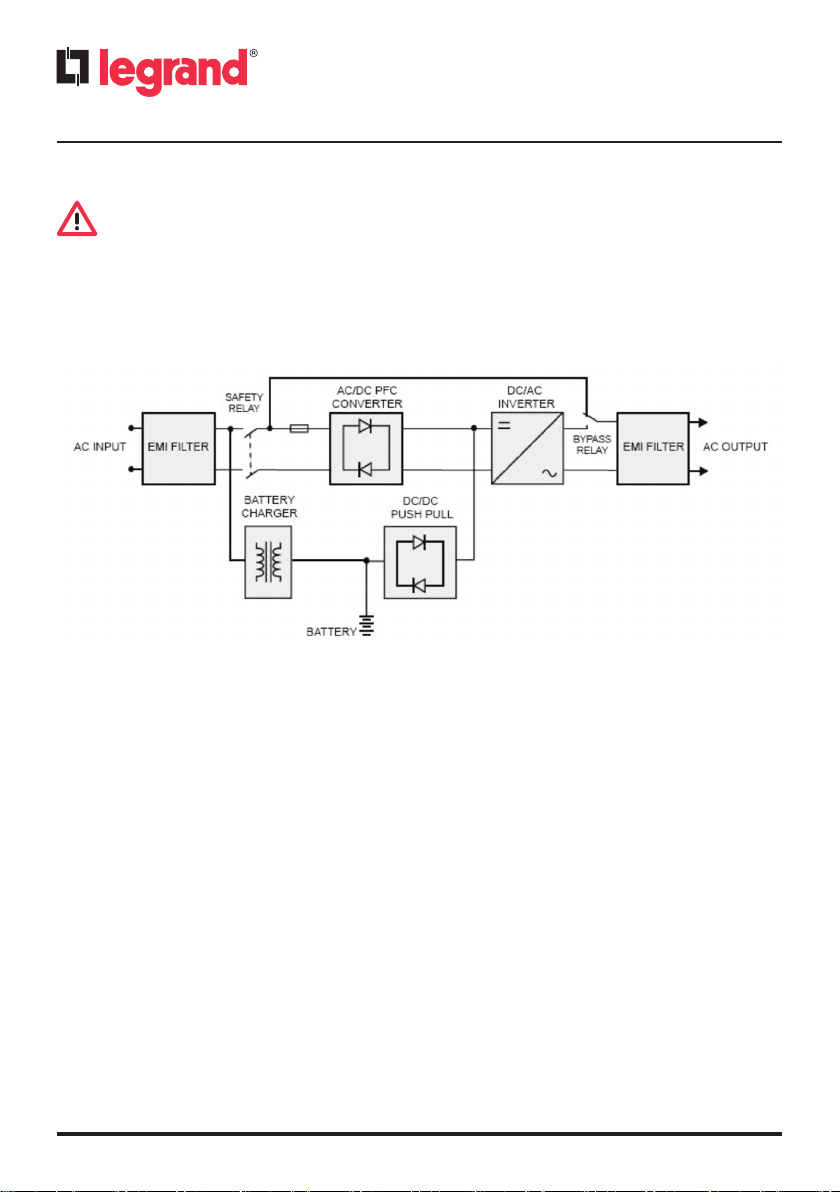
The following diagram illustrates the architecture of the UPS system:
The major modules consist of:
• An AC-to-DC power converter (rectifier) with PFC control circuit.
• A DC-to-AC high frequency inverter.
• A battery charger.
• A battery bank.
• A DC-to-DC push/pull converter control circuit.
• A static bypass loop.
• Input and output EMI filters.
34
Page 4

DAKER DK Plus
1 kVA - 3 kVA
1.1 Use of the manual
This manual must be kept in a safe, dry place and must always be available for consultation.
The manual reflects the state of the art when the equipment was put onto the market. This publication conforms to the standards current on that date; the manual cannot be considered inadequate when new standards come into force or modifications are made to the equipment.
INDICATION
The installation manual is an integral part of the equipment supplied and must therefore be kept
for its entire lifetime. In case of need (for example in the case of damage that even partially compromise its consultation) a new copy must be requested from the Manufacturer, quoting the publication code on the cover.
1.2 Guarantee terms
The terms of the guarantee may vary depending on the country where the UPS is sold. Check the
validity and duration with LEGRAND’s local sale representative.
The Manufacturer declines all indirect or direct responsibility arising from:
- failure to observe the installation instructions and use of the equipment which differs from the
specifications in the installation manual;
- use by personnel who have not read and thoroughly understood the content of the installation
manual;
- use that does not comply with the specific standards used in the country where the equipment
is installed;
- modifications made to the equipment, software, functioning logic unless they have been authorized by the Manufacturer in writing;
- repairs that have not been authorized by the LEGRAND Technical Support Service;
- damage caused intentionally, through negligence, by acts of God, natural phenomena, fire or
liquid infiltration.
EN
1.3 Copyright
The information contained in this manual cannot be disclosed to third parties. Any partial or total
duplication of the manual which is not authorized in writing by the Manufacturer, by photocopying or other systems, including by electronic scanning, violates copyright conditions and may lead
to prosecution.
LEGRAND reserves the copyright of this publication and prohibits its reproduction wholly or in
part without previous written authorisation.
35
Page 5
2 Safety Instructions
This section contains important safety instructions that should always be followed during the installation, use and maintenance of the UPS.
• This product should be installed in compliance with installation rules, preferably by a qualified
electrician. Incorrect installation and use can lead to risk of electric shock or fire. Before carrying out the installation, read the instructions and take account of the product’s specific mounting location. Do not open up, dismantle, alter or modify the device except where specifically
required to do so by the instructions. All Legrand products must be opened and repaired exclusively by personnel trained and approved by Legrand. Any unauthorised opening or repair
completely cancels all liabilities and the rights to replacement and guarantees. Use only Legrand
brand accessories.
• If any visible damage is found on the product during the unpacking operation, do not install the
UPS but repack the unit and return it to your reseller or distributor.
• Before operating the UPS or connecting any load equipment, ensure the UPS is connected to a
properly grounded electrical supply.
• The load applied must not exceed the one indicated on the type label of the UPS.
• The ON/OFF button of the UPS does not electrically isolate the internal parts. To isolate the UPS,
unplug it from the mains power socket.
• Do not attempt to open or disassemble the UPS; there are no user replaceable parts. Opening
the case will void the warranty and introduces the risk of electric shock even when the mains
plug is disconnected.
• The mains socket outlet that supplies the UPS shall be installed near the UPS and shall be easily
accessible.
• Do not plug non-computer-related items such as medical, life-support and house electric equip-
ments to the UPS output.
• Do not plug laser printers to the UPS output because they have a high start-up current.
• The UPS has its own internal energy source (batteries). If the UPS is switched on when no AC
power is available, there is hazardous voltage at the output sockets.
The batteries inside the UPS are not user-replaceable. Servicing of batteries must be
performed only by electrical hazard authorized personnel.
CAUTION: A battery can present a risk of electrical shock and high short circuit current.
The following precautions should be observed when working on batteries:
a) Remove watches, rings or other metal objects.
b) Use tools with insulated handles.
c) Wear rubber gloves and boots.
d) Do not lay tools or metal parts on top of batteries.
e) Disconnect the charging source prior to connecting or disconnecting battery terminals.
f) Determine if battery is inadvertently grounded. If inadvertently grounded, remove source
from ground. Contact with any part of a grounded battery can result in electrical shock.
36
Page 6
DAKER DK Plus
1 kVA - 3 kVA
The likelihood of such shock can be reduced if such grounds are removed during installation and maintenance (applicable to equipment and remote battery supplies not having a
grounded supply circuit).
CAUTION: Do not dispose of batteries in a fire. The batteries may explode.
CAUTION: Do not open or mutilate batteries. Released electrolyte is harmful to the skin and
eyes. It may be toxic.
• This UPS has dangerous high voltages on its input and output connections. Contact with these
voltages may be life threatening.
• In case of emergency, immediately turn off the equipment and disconnect the power cord from
the AC power supply to disable the UPS.
• Do not allow any liquid or any foreign object to enter the UPS.
• The UPS is intended for indoor installation in a ventilated, controlled indoor environment with
a range of temperature between 0°C (+32°F) and +40°C (+104°F) and non-condensing humidity
between 20% and 80%.
• Do not install the UPS in locations with sparks, smoke and hazardous gas or where there is water
and excessive humidity. Dusty, corrosive, and salty environments can damage the UPS.
• Do not plug the UPS input into its own output.
• Do not attach a power strip or surge suppressor to the UPS.
• Do not cover the cooling vents and keep a clearance of 20 cm beyond the UPS rear panel. Avoid
exposing it to direct sunlight or installing it near heat emitting appliances.
• Unplug the UPS prior to cleaning and do not use liquid or spray detergent.
• Do not place the UPS near equipments that generate strong electromagnetic fields and/or near
equipments that are sensible to electromagnetic fields.
WARNING
All the UPSs are category C2 products according to the EN 62040-2. In a residential environment, these equipments may cause radio interference, in which case the user may be required to take additional measures.
EN
37
Page 7
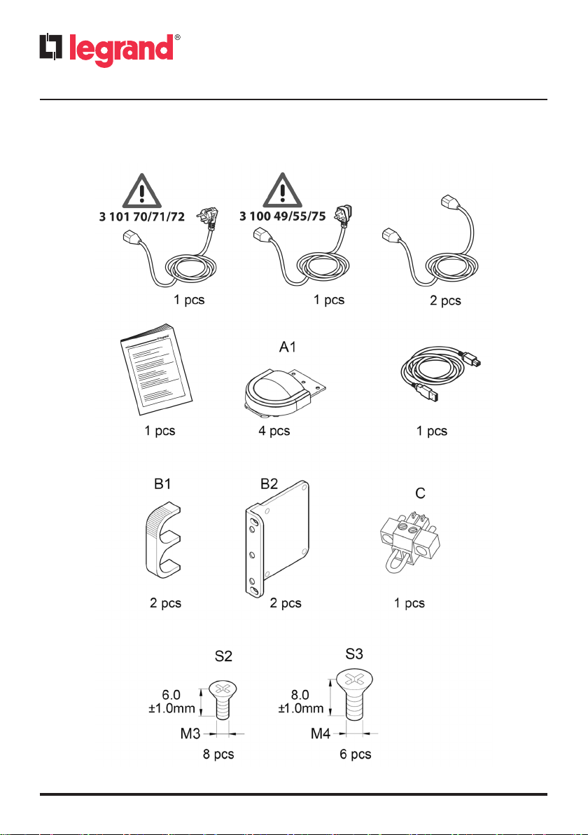
3.1 Package content
Check for the following package content:
3 Installation
38
Page 8
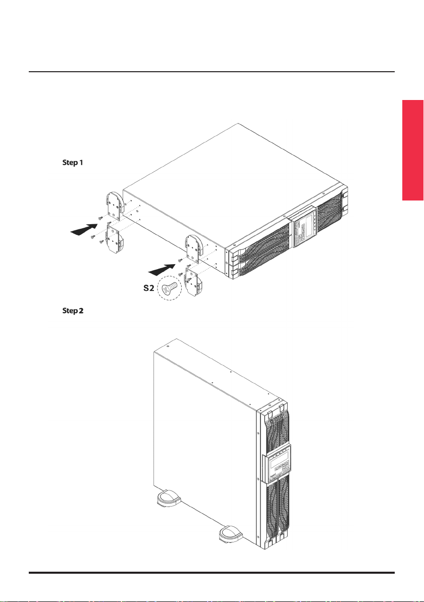
3.2 Tower configuration setup
3.2.1 UPS
DAKER DK Plus
1 kVA - 3 kVA
EN
39
Page 9
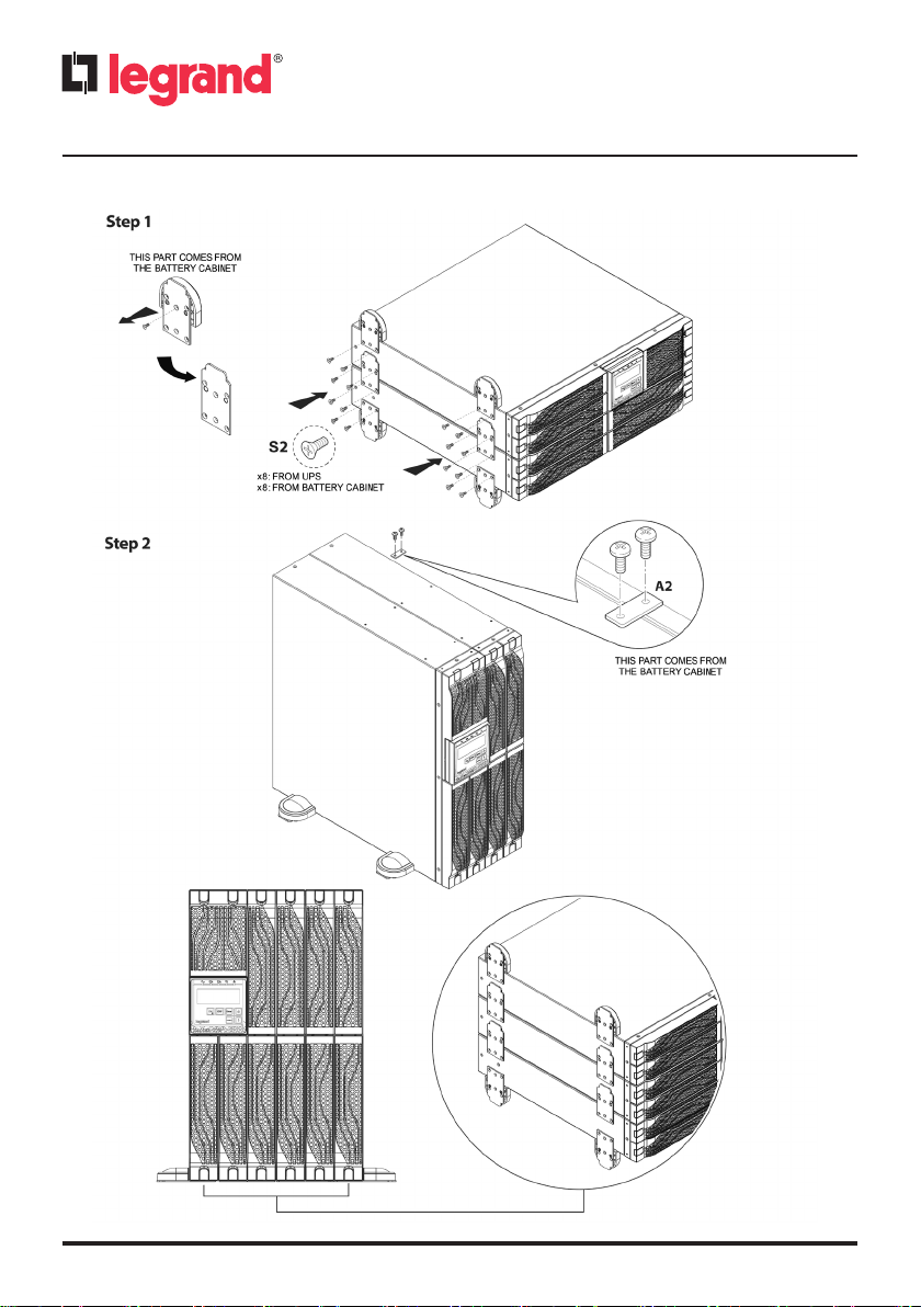
3.2.2 UPS + battery cabinet (optional)
3 Installation
S1
40
Page 10

DAKER DK Plus
1 kVA - 3 kVA
3.3 Rack configuration setup
INDICATION
For the rack configuration setup it is also possible to use the rack support bracket kit 3 109 52. In
this case, follow the instruction sheet contained in the kit.
EN
41
Page 11

3 Installation
42
Page 12

3.4 Rear panel
DAKER DK Plus
1 kVA - 3 kVA
EN
1. Emergency Power Off (EPO)
2. USB port
3. RS-232 port
4. Cooling fans
5. External battery connector
6. SNMP slot
7. AC input inlet
8. Input circuit breaker
9. Output circuit breakers
10. IEC type F outlets
11. IEC type J outlet
43
Page 13

3 Installation
3.5 Installation procedure
WARNING
Read the safety instructions on chapter 2 before installing the UPS.
1. Position the UPS so that the cooling fans are not obstructed, as visible in the following figure:
2. Connect the IEC input and output cables provided to the appropriate inlet and outlets.
3. Connect the loads to the IEC output cables, ensuring that the switches of the various loads are
in the off position.
4. Plug the UPS input cable into a main socket with a suitable voltage and current.
5. Connect the EPO contact in the UPS (normally closed)
44
Page 14

4 Operation
4.1 Control Panel
4.1.1 LCD Panel
DAKER DK Plus
1 kVA - 3 kVA
EN
ITEM DESCRIPTION
a
b
c d
e
f
g
h
i
j
k
l
Display
The steady green LED indicates that the mains voltage is within the admittable
input voltage range
The green LEDs indicate that the programmable outlets 1 and 2 are activated
The green LED blinks if the UPS is in bypass mode.
The steady green LED indicates that the UPS is in ECO mode.
The steady red LED indicates that there is an alarm
UPS power ON/Silence alarm
UPS power OFF
Special functions access menu
Go to the next screen
Go to the previous screen or change the setting of the UPS
Confirm a changed setting
45
Page 15

4.1.2 Display description
SIGN DESCRIPTION
4 Operation
Bypass Fault
Utility Input Fault
Site wiring Fault
Buzzer Silent
Overload
46
UPS Service mode
(reserved for LEGRAND Technical Support Service)
Alarm
UPS operation diagram
3-Digit Measurement Display
Measured item
Battery fault
Battery low
Battery test
Page 16

DAKER DK Plus
1 kVA - 3 kVA
4.2 Operating modes
UPS OPERATING MODE LEDs/DISPLAY INDICATION BUZZER
NORMAL MODE
on-line, double conversion
STORED ENERGY MODE
The loads are supplied through
the batteries connected
to the UPS
BYPASS MODE
The loads are supplied directly
from the mains. The UPS does
not protect the loads.
The UPS is in bypass mode after
a setting shortcut (paragraph
4.7), a generic alarm
or a prolonged overload
in normal mode.
ECO MODE
The loads are supplied directly
from the mains through
the automatic bypass circuit
inside the UPS. The output
voltage and frequency
are the same as the mains.
CVCF 50/60
The UPS maintains constant the
output voltage and the output
fre quency to 50 Hz or 60 Hz
according to the setting.
With this operating mode it is
available only the 75% of the
nominal output power.
LEDs: steady
DISPLAY:
LEDs: steady
DISPLAY:
LEDs: steady
DISPLAY:
LEDs: steady
DISPLAY:
LEDs: steady
DISPLAY:
, ,
, ,
, ,
, , ,
, ,
No sound
Beep every
second
Beep every two
seconds
No sound
No sound
EN
See also paragraph 4.6 to set the operating mode.
47
Page 17

4 Operation
4.3 Start-up procedure
4.3.1 Normal mode
1. Make sure the input breaker is not tripped. If it is, reset it.
2. Plug the UPS input cable into the mains socket.
3. The UPS turns to the standby mode in 5 seconds. The green LED
voltage is within the admittable range and the fans spin. The battery charger is active. In this
condition the loads are not powered. The display looks like the following figure:
4. Press and hold it until the buzzer sounds twice.
lights up if the input
The green LEDs
5. The start-up procedure is completed. Make sure that the batteries are fully charged or that the
UPS has been plugged to the wall receptacle at least for 4 hours before connecting the loads.
light up. The display looks like the following figure:
4.3.2 Cold start
1. Make sure the internal batteries or the external battery cabinets are connected to the UPS.
2. Press
the following figure:
3. Press again and hold it until the buzzer sounds twice. If the second key confirmation is not
completed within 10 seconds, the UPS does not perform the cold start and shuts off.
and hold it until the buzzer sounds twice; then release the key. The display looks like
48
Page 18

DAKER DK Plus
1 kVA - 3 kVA
4. Few seconds after the second key confirmation, the UPS turns on in stored energy mode and the
loads are powered. The alarm LED
an intermittent sound alarm.
The display looks like the following figure:
5. The start-up procedure is completed. If the UPS is not plugged to the mains outlet, the loads are
powered till the end of the backup time.
INDICATION
The output frequency is the same that there was at the input before the UPS was shutdown. The
default value is 50 Hz but if before the UPS shutdown the input frequency was 60 Hz, then the
output frequency after the cold start will be 60 Hz.
4.4 Shutdown
1. Press and hold until the buzzer sounds twice.
2. The UPS stops powering the loads and turns to the standby mode. The green LEDs
switch off. The ventilating fans continue spinning.
3. Unplug the UPS from the wall receptacle if there is still input voltage. After 10 seconds, the fans
stop working and the UPS completely shuts down.
and the green LEDs light up. It is audible
EN
4.5 UPS Measurements
After the UPS is turned on, it is possible to check the UPS measurements by pressing or
.
The display sequence is:
- AC input voltage and current;
- AC input frequency;
- output voltage;
- output frequency;
- load percentage;
- output current;
- battery voltage;
- battery autonomy;
- UPS internal temperature;
- battery status, real and apparent power.
49
Page 19

4 Operation
4.6 UPS settings
After the UPS is turned on, it is possible to check the UPS settings by pressing . The different
parameters can be scrolled pressing
It is possible to change only three parameters while the UPS is supplying the loads. One of these is
reserved to the LEGRAND Technical Support Service.
PARAMETER SETTING DISPLAY
BUZZER
.
ON
OFF
OFF
QUICK
BATTERY TEST
BATTERY STATUS
TEST
This function
is reserved to
the LEGRAND
Technical Support
Service and must
not be activated
by the user
50
ON
OFF
ON
Page 20

Follow this procedure to change the buzzer setting:
DAKER DK Plus
1 kVA - 3 kVA
- press the
- press
- confirm the choice by pressing
The quick battery test can be performed to check the operation of the batteries. The test must be
performed only after the batteries are fully charged, the mains is available and the UPS is powering
the loads. Follow this procedure to perform the battery test:
- press
- press
- press
the loads are always powered with no voltage dip;
- if at the end of the test the UPS transfers back to normal mode without any alarm code, the bat-
teries are working properly.
To change all the other settings, the UPS must be in standby mode. In this condition the loads are
not powered, therefore all the needed settings must be performed before turning on the UPS.
Follow this procedure to change the UPS settings:
- press simultaneously
twice. The LCD displays the first setting indicated in the next table (“buzzer”);
- all the different settings can be scrolled pressing
- except for the buzzer and the battery test, all the other settings may be changed by pressing
;
. The buzzer setting is displayed;
to select ON or OFF;
.
;
to display the battery test setting;
to select ON. The UPS transfers to stored energy mode for 10 seconds. During the test,
and for approximately three seconds, until the buzzer sounds
;
EN
- after changing settings, scroll to the “End” screen and then press
- the UPS restarts automatically. However, it is also suggested to remove the mains for at least 30
seconds.
to save all changes;
51
Page 21

PARAMETER SETTING DISPLAY
ON
BUZZER
(this setting can’t be
changed with this
procedure)
OFF
QUICK
BATTERY TEST
(this setting can’t be
changed with this
procedure)
BATTERY
STATUS TEST
(this setting can’t
be changed with
this procedure and
it is reserved to the
LEGRAND Technical
Support Service)
OFF
OFF
4 Operation
BYPASS VOLTAGE
RANGE
52
LOW
HIGH
Page 22

DAKER DK Plus
1 kVA - 3 kVA
PARAMETER SETTING DISPLAY
If during the normal
BYPASS
FREQUENCY
RANGE
OUTPUT
VOLTAGE
functioning the bypass
frequency goes beyond
the setting, the UPS
enters in lock mode
(alarm and output
disconnected)
120 V
208 V
220 V
230 V
240 V
NORMAL MODE
EN
OPERATING
MODE
(see paragraph
4.2)
ECO MODE
CVCF 50 Hz
CVCF 60 Hz
53
Page 23

PARAMETER SETTING DISPLAY
0 %
- 1 %
- 2 %
- 3 %
+ 3 %
OUTPUT
VOLTAGE
ADJUSTMENT
functioning of the UPS
slightly below or above
the desired value, this
setting allows to adjust it
+ 2 %
+ 1 %
If during the normal
the output voltage is
4 Operation
EXTERNAL
BATTERY
CABINETS
END SCREEN
INDICATION
If the UPS is connected to one or more battery cabinets, it is necessary to set their number to
fore cast a realistic backup time. This can be done from the display of the UPS or by using the software “UPS S etting Tool”.
external battery cabinets
1c - 9c
Select the number of
connected to the UPS
Press
to save all
changes
54
Page 24

4.7 Settings shortcuts
There are two settings shortcuts:
DAKER DK Plus
1 kVA - 3 kVA
- Bypass Mode: while the UPS is in normal mode (on-line, double conversion) press
simultaneously for approximately three seconds, until the buzzer sounds twice. The UPS
transfers from normal mode to bypass mode. During this functioning mode, the bypass LED
blinks and the buzzer sounds intermittently. Press again and simultaneously
until the buzzer sounds twice to return to normal mode.
- Eco Mode: while the UPS is in normal mode (on-line, double conversion) press
simultaneously for approximately three seconds, until the buzzer sounds twice. The UPS transfers from normal mode to eco mode. During this functioning mode, the bypass LED
Press again
mode.
and simultaneously until the buzzer sounds twice to return to normal
and
and
is on.
4.8 Emergency Power Off (EPO)
The UPS has an external normally closed contact that can be opened to activate the immediate
stop of the UPS. It is possible to connect to each other several EPO contacts of UPS Daker DK Plus
to a unique emergency pushbutton.
The EPO terminal is at the back of the UPS and it is needed for the functioning of the UPS.
EN
55
Page 25

4 Operation
4.9 Communication devices
The UPS has one RS232 serial port, one USB port and one SNMP slot.
Only one communication interface at a time can control the UPS, according to the following priority:
1) optional interface card;
2) USB;
3) RS232.
The following figures show the pinout of the RS232 and USB interfaces:
Pin 3: RS-232 Rx
Pin 2: RS-232 Tx
Pin 5: Ground
Pin 1: VCC (+5V)
Pin 2: D Pin 3: D+
Pin 4: Ground
It is possible to download some free of charge software from the website http://www.ups.legrand.com
The software can be used for the following functions:
- display of all the operations and diagnostic data in case of problems (UPS Communicator);
- setup of special functions (UPS Setting Tool). For instance, the UPS has two programmable out-
puts for less critical loads. These sockets may be disabled or timed during stored energy mode to
ensure the supply of the more critical loads;
- automatic shutdown of the local computer (UPS Communicator).
56
Page 26

5 Troubleshooting
INDICATION DIAGNOSTIC SOLUTION
Fault LED
Check the error code on
the display
(see error code table)
The UPS doesn’t work
in stored energy mode
or the backup time is
shorter than its intended
performance.
The UPS is working
normally but the loads are
not powered
Er05, Er39
intermittent sound
alarm
Er12
continuous alarm sound
Site wiring/Ground fault
Er11, Er14
intermittent sound
alarm
other error codes
-
-
DAKER DK Plus
1 kVA - 3 kVA
The batteries don’t work properly.
Check for proper battery connection
and measure battery voltage to ensure
that batteries are charged.
Recharge the batteries for 8 hours.
If the problem persists or if it is
necessary to replace them, contact the
LEGRAND Technical Support Service.
Disconnect some non-critical loads
from the UPS output until the overload
ceases.
Check if there is any short-circuit between
the output cables due to a faulty
insulation. Replace the cables if necessary.
Check if the power cord is properly
plugged, respecting the “L” and “N”
wires. If not, re-plug the cord on the
socket turning it of 180°.
If the power cord is properly plugged,
check if the ground-neutral voltage
exceeds the limits.
Verify that the ventilating fans work
properly.
If the problem persists or if it necessary
to replace them, contact the LEGRAND
Technical Support Service.
Check the error code table.
If the problem persists, contact the
LEGRAND Technical Support Service.
If the backup time remains
unsatisfactory after 8 hours of battery
charging, contact the LEGRAND
Technical Support Service.
Check that all power cords are properly
connected.
If the problem persists, contact the
LEGRAND Technical Support Service.
EN
57
Page 27

5 Troubleshooting
INDICATION DIAGNOSTIC SOLUTION
The UPS switches into
stored energy mode and
then back into normal
mode when a connected
device is turned on or the
UPS switches back and
forth between the two
modes.
Strange noise or smell -
The UPS switches o after
a total discharge of the
batteries
Error code table
ERROR CODE MEANING
Er05 Battery weak or faulty
Er06 Output short-circuit
Er07 EPO mode
Er11 UPS over-temperature
Er12 Inverter overload
Er14 Fans out of order
Er28 Bypass overload
Er39 Battery problem during the start-up process of the UPS
-
-
A power strip could be connected to
the UPS. Do not use it.
See also if there is any damage to the
utility wall receptacle or if the cord plug
is faulty. Replace them if needed.
If the problem persists, contact the
LEGRAND Technical Support Service.
Shut down immediately the UPS.
Disconnect the mains and contact the
LEGRAND Technical Support Service.
The function of autorestart is enabled
by default. When the mains is available,
the UPS restarts in normal mode to
supply the loads.
58
Page 28

DAKER DK Plus
1 kVA - 3 kVA
6 Warehousing and dismantling
6.1 Warehousing
The UPS must be stored in an environment with a room temperature between +20°C (+68°F) and
+25°C (+77°F) and humidity less than 90% (not condensing).
The batteries installed inside the UPS are lead/acid sealed and do not require maintenance (VRLA).
The batteries should be charged for 12 hours every 3 months by connecting the UPS to the utility supply. Repeat this procedure every two months if the storage ambient temperature is above
+25°C (+77°F).
CAUTION
The UPS must never be stored if the batteries are partially or totally discharged.
LEGRAND is not liable for any damage or bad functioning caused to the UPS by wrong warehousing.
6.2 Dismantling
DANGER
Dismantling and disposal operations may only be done by a qualified electrician. These instructions are to be considered indicative: in every country there are different regulations with regard
to the disposal of electronic or hazardous waste such as batteries. It is necessary to strictly adhere
to the standards in force in the country where the equipment is used.
Do not throw any component of the equipment in the ordinary rubbish.
Batteries must be disposed of in a site intended for the recovery of toxic waste. Disposal in
the traditional rubbish is not allowed.
Apply to the competent agencies in your countries for the proper procedure.
EN
WARNING
A battery may constitute a risk of an electric shock and high short-circuit current.
When working on batteries, the prescriptions indicated in chapter 2 are to be adhered to.
It is important to dismantle the various parts the UPS consists of. For these operations, Personal
Protective Equipment must be worn.
Sub-divide the components separating the metal from the plastic, from the copper and so on according to the type of selective waste disposal in the country where the equipment is dismantled.
If the dismantled components must be stored before being properly disposed, be careful to keep
them in a safe place protected from atmospheric agents to avoid soil and groundwater contamination.
For the disposal of electronic waste it is necessary to refer to the industry standards.
This symbol indicates that in order to prevent any negative eects on the environment
and on people, this product should be disposed of separately from other household
waste, by taking it to authorised collection centres, in accordance with the EU countries
local waste disposal legislations. Disposing of the product without following local regulations may be punished by law. It is recommended that you check that in your country this product is subject to WEEE legislations.
59
 Loading...