

Page 1
®
Daker DK 4.5-10 kVA
Parallel installation quick start
Part. LE08927AA-09/15-01 GF
Page 2

Daker DK 4.5-10 kVA
®
ENGLISH 3
UK
2
Page 3

Daker DK 4.5-10 kVA
Index
Introduction 2
1 Important Safety Instructions 2
2 Parallel system installation 3
3 Single Unit Check 5
4 Parallel Setting 7
4 Parallel Mode Start up 8
5 Trouble Shooting 9
3
Page 4

®
Introduction
This document is a reference guide to install the Daker DK UPS 4,5-10kVA in parallel for N+1
redundancy operation. The parallel installation and configuration procedure is divided in 4 phases :
Parallel system installation – To physically connect each unit.
Single Unit check – To verify and confirm that each unit works properly with the correct
parameters and output voltage
Parallel Setting – To setup each units’ parameters to work in parallel mode.
Parallel Mode Start up – To verify that the parallel system works normally.
1 Important Safety Instructions
• Only qualified and trained electricians are allowed to install the UPSs in single unit or parallel
systems.
• Please read the Installation guide carefully before installing these UPSs to avoid electrical
hazards or damages to the UPS and the loads connected.
• To prevent potential leakage current hazard, ensure that the AC main supply is securely grounded.
• Please note that the Parallel function of the UPS can be enabled only in “Normal Mode” operation.
• Before to set a parallel installation, ensure that the output voltage tolerance for each UPS at
zero-load condition is less than 0.5Vac.Please consult your authorized dealer if any of the UPS
output voltage has the tolerance over 0.5Vac.
• Ensure that the communication cables plugged into the UPS RJ45 connectors are connected
securely to avoid damage to both the UPS and the output devices.
• Ensure that two and only two UPS units of the parallel system have the terminal resistors on the
rear set in “On” position.
• Only UPS with the same rating and type can be installed in parallel.
• Please ensure to add a 40Arms/250Vac and 30Arms/250Vac NFB(Non-fuse Breaker)at the input
and output of each UPS respectively.
4
Page 5
Daker DK 4.5-10 kVA
2 Parallel system installation
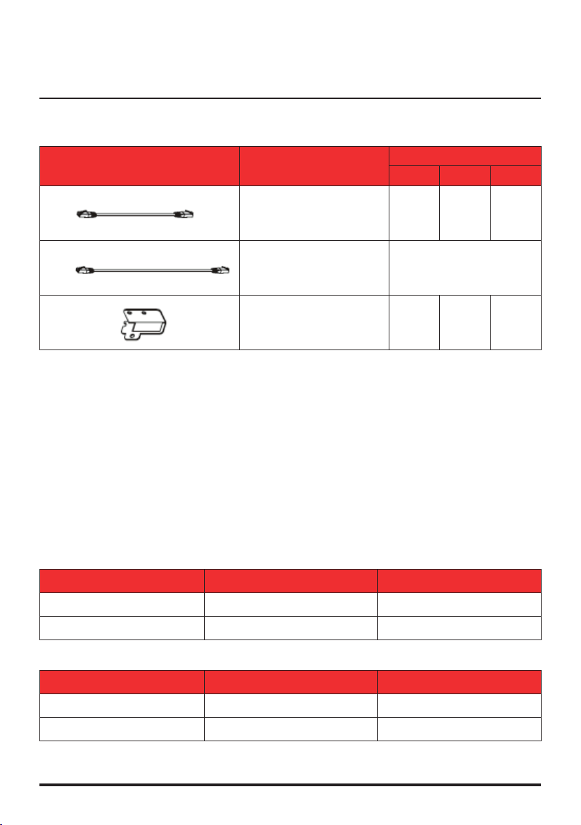
Accessories
The following accessories (included in the parallel kit) are requested to install the UPS in parallel mode.
ACCESSORIES DESCRIPTION
Standard cat5 cable
C1
C2
F1
• The design of the air flow for the convertible UPS is to flow in from the front ventilation holes
to the rear ventilation holes.
It is recommended to leave at least 30 cm around the UPS and Battery bank to allow good
ventilation conditions.
Please refer to the UPS manual for the detailed installation guide.
• To reduce noise interference do not cross or mix input , output, and battery cables.
• Please install the communication wires for parallel and control signal functions (including
cat5, serial, usb and EPO cables) keeping them away from input/output and battery cables.
• To prevent potential leakage current hazard, ensure that the AC main supply is securely
grounded.
• Please refer to the single UPS input/output current specifications and recommended conduc-
tors listed below:
AC input and output
with Rj45 connector
(max length: 1050mm)
Standard cat5 cable
with Rj45 connector
(max length: 1900)
Bracket to secure
C1 and C2 to the UPS box
QUANTITIES
2 UPS 3 UPS 4 UPS
x 1 x 2 x 3
x 1
x 2 x 3 x 4
MODEL MAXIMUM CURRENT CONDUCTOR SECTION
4,5-6KVA 33A AWG #9
Battery Input
MODEL MAXIMUM CURRENT CONDUCTOR SECTION
4,5-6KVA 25A AWG #10
10KVA
10KVA
54,3A AWG #7
41A AWG #10
5
Page 6

®
2 Parallel system installation
Recommended Circuit Breakers to be installed at the UPS input/output
MODEL INPUT CBi OUTPUT CBo
4,5-6KVA 40A 30A
10KVA
The breaker type should be “C” or “D” with the following current ratings:
• Install and connect the UPS units according to the diagrams in figure 2, 3, 4, 5.
CAUTION
The MTBS is an optional for maintenance.
63A 63A
Figure 1
CBi : installation input breakers
CBo : installation output breakers
CB1 : UPS utility input breaker
6
Utility input
UPS output
Page 7

Daker DK 4.5-10 kVA
• Connect the parallel CAT5E cables as a “Ring Network” (Figure 3) using the parallel kit plate to
fix them to the UPS rear panel (Figure 4)
2 units parallel
3 units parallel
4 units parallel
Figure 2 Figure 3
CAUTION
The maximum length of the communication connecting wires shall be less than 7M.
All the Input/ output power cable should have the same length (max 25m)
1050mm RJ-45
communication
connecting wire
1900mm RJ-45
communication
connecting wire
Max. 25M; all Input
Power cables shall
be with the same
lenght
1900mm RJ-45
communication
connecting wire
Figure 4
7
Page 8

®
3 Single Unit Check
Parameters Check
CAUTION
The following operations have to be done on each UPS separately and independently.
• Ensure that all the circuit breakers at the input (Cbi) and output (Cbo) are set to off position.
• Ensure that all the utility input breakers (CB1) for each UPS is set to off position
• Turn on the AC input of the UPS to be checked :
Turn on only the input breaker CBi connected to the UPS to be checked, and the utility breakers
CB1 on the rear panel of the UPS itself. DO NOT TURN ON THE INVERTER !
Figure 5
• Enter in setting mode by pressing <On> & <
• Verify that all the UPS’s parameters match with the default values (Table 1)
8
> keys simultaneously for 3 seconds (Figure 6).
Page 9

Daker DK 4.5-10 kVA
Item
Press < >
to change
Buzzer on/off
Self-Test
Bypass Voltage
Range
Inverter Synchronize
Frequency range
Inverter
Output Voltage *
Operation Mode
Output Voltage
Adjustment
Default
Display List
Press <
> to change
(Available in Line-Mode Only)
Parallel ID
Number **
Parallel Function
On/Off ***
SAVE
After Saved
UPS Locked
Table 1
** Single unit ID number must be “01”, or UPS will have an Er17 error occurred.
*** Single unit Parallel function must be “OFF” (P 01), or UPS will have an Er21 error occurred.
Press < > to Save
Shut off AC input power to reset the UPS
9
Page 10

®
3 Single Unit Check
CAUTION
“Bypass Voltage Range”, “Inverter Synchronize Frequency Range”, “Inverter Output Voltage”
and “Output Voltage Adjustment“ are adjustable parameters but for parallel function eve-
ry unit must have the same settings
• Change item by pressing <
setting.
• Turn off the UPS utility input breaker (CB1) while the LCD shows “LINE OFF” to reset the UPS.
> until the display shows the text “Save”. Press < Enter > to save the
Basic Function Check
• Turn on the AC input (UPS utility input breaker) and then turn on the UPS inverter (press <ON>)
• Test the UPS switching from normal mode to stored energy mode and viceversa
• Verify that the LCD panel works normally and doesn’t display errors.
Output Error Voltages Check
• Verify the output voltage for each UPS unit (at 0 load), and make sure the voltage difference
between each unit is under 0.5Vac.
• If the voltage difference is between 0.5~1.0Vac, the parallel error current will be higher.
• If the voltage difference is over 1.0Vac, a calibration should be performed on the unit(s) which
has over-limit error voltage otherwise the parallel could fail (If this condition occurs please contact your local dealer for technical support)
Turn off the inverter (press <off>) and then the AC input (Turn off CBi and the UPS utility input
breaker) and restart the process for the next unit.
10
Page 11

Daker DK 4.5-10 kVA
4 Parallel Setting
Terminal resistor setting
Each UPS unit is equipped with a terminal resistor “S1” placed on the rear panel (Figure 7) besides
the RJ45 connectors.
• Set the terminal resistor according to the configuration shown in the Table 2
PARALLEL UNITS
2 UNITS ON ON -- --
3 UNITS ON OFF ON --
4 UNITS
Table 2
CAUTION
Only 2 UPS units must have the terminal resistor in ON position. A wrong Terminal Resistor
setting will cause unpredictable failure or UPS burned out. Eventual error can’t be detected
automatically by the UPS.
TERMINAL RESISTOR STATUSOUTPUT CBo
UPS1 UPS2 UPS3 UPS4
ON OFF OFF ON
Parallel Function Enable and ID Numbers setting
• Ensure that all the circuit breakers at the input and output are set to off position.
• Turn on the AC input of the UPS to be configured
Turn on only the input breakers CBi connected to the UPS to be checked, and the utility breakers
CB1 on the rear panel of the UPS itself.
DO NOT TURN ON THE INVERTER !
• Enter the UPS in Setup Mode (See single unit check)
• Set the UPS ID . Each UPS must have a different ID number.
CAUTION
One of the UPS must have the “Id01”. This UPS will be the default master unit of the parallel
system.
11
Page 12

®
4 Parallel Setting
• Set the Parallel function to “Enable” (P 02)
UPS# UPS#1 UPS#2 UPS#3 UPS#4
ID NUMBER
PARALLEL
FUNCTION
Table 3
Turn off the inverter and then the AC input (Turn off CBi and CB1 of the UPS) and restart the process
for the next unit.
4 Parallel Mode Start up
Er21 Check (Communication Failure or Can not find ID1 unit)
• Ensure that the AC input and the inverter is off for all the UPS connected.
• Turn on the AC input only for UPS#2, UPS#3, UPS#4
The UPS#2, UPS#3, UPS#4 LCD will show “Er21”.
• Turn on UPS#1 AC input.
The UPS#2, UPS#3, UPS#4 stop showing “Er21”
UPS# UPS#1 UPS#2 UPS#3 UPS#4
TEST AC OFF
TEST OK
Table 4
If the error Er21 still appear on the display of one UPS please verify and eventually repeat the
setting and wiring process described above to solve eventual communication problem.
CAUTION
do not start the UPSs inverters before the Er21 test is passed to avoid unpredictable failures
or damages.
12
Page 13

Daker DK 4.5-10 kVA
4 Parallel Mode Start up
Start up procedure
• Ensure that the input and output circuit breakers are set to off position for all the UPS.
• Turn on the input breaker (CBi and CB1) of all the UPS connected ( all the units are now in bypass mode)
• Turn on the inverter of the first unit (ID01). The other units will turn off the bypass line.
• When the bypass line of the other UPSs is off, turn on them progressively.
• Turn on all the output breakers connected to the UPSs (CBo and CBoutput)
Redundancy Function Check
If the parallel system is working properly ( N+1 redundancy operation) the N+1 redundancy LED
is on.
CAUTION
If the N+1 led is off the loads exceed the
redundancy level. The load has to be reduced
until the N+1 redundancy LED turn ON.
• To verify that the redundancy function indicator works properly repeat the start up procedure
turning on only part of the UPS connected in parallel, and apply a load above the values shown
in the below table, the N+1 LED will turn off.
PARALLEL UNITS
2 UNITS 50%
3 UNITS 66%
4 UNITS
• If the redundancy check is positive repeat again the start up procedure turning on all the UPS
connected
The Installation procedure is finished !
REDUNDANCY LEVEL LOAD %
75%
13
Page 14

®
5 Trouble Shooting
ERROR DESCRIPTION CAUSE
Er16 Output
Parameters
Setting Error
Er17 ID Numbers in
conict in or ID
number Error in
single unit
Er27 The UPS Must
Be Operated in
Normal-Mode in
Parallel System
Er08 DC BUS High
Level Abnormal
If an Er16 appear during
the parallel installation test,
then there are one or more
parameters setting conict
between the UPS units.
1. Two or more units have
the same ID number.
(Parallel system)
2. Parallel function is not
enabled, but ID number is
not 01. (Single unit)
The UPS is not working
in “Normal Mode.
“ECO Mode” and
“Frequency-Converter Mode”
are not supported
for parallel system.
1. If the output voltage
dierence between each
unit is higher than 1.0Vac,
an Er08 could
Appear on the display
panel during the parallel
system start up.
2. Improper installation
or parallel system
communication failure.
POSSIBLE
SOLUTION
Possible solution: repeat
the process described in the
paragraph “parameters check“
2and make sure that the
common setting are the same
for each units Process test 1.1
and check each parameters
are the same setting between
each unit.
1. Change ID number setting.
2. Change ID number as 01.
Change UPS setting as
“Normal mode”.
1. Check the inverter output
voltage independently for
each unit and apply the
calibration procedures to
the units with abnormal
output voltage.
2. Check the parallel setting
and repeat the Er-21
checks described in the
Test start up paragraph.
Er34 Balance
Function
Conict
14
New UPS version unit(s)
paralleled with older version
unit(s).
Use “UPS Setting Tool”
software to enable special
function ag #8 to make the
new version compatible with
the old one
Page 15

Page 16

World Headquarters and
®
International Department
87045 LIMOGES CEDEX FRANCE
: 33 5 55 06 87 87
Fax : 33 5 55 06 74 55
www.legrandelectric.com
Legrand se réserve le droit de modier à tout moment le contenu de cet imprimé et de communiquer,
sous n’importe quelle forme et modalité, les changements apportés.
 Loading...