

Page 1
INSTRUCTION / INSTALLATION SHEET
5-Port Fast Ethernet Switch
301 Fulling Mill Road, Suite G
Middletown, PA 17057
Phone (800) 321-2343 / Fax (717) 702-2546
www.onqlegrand.com
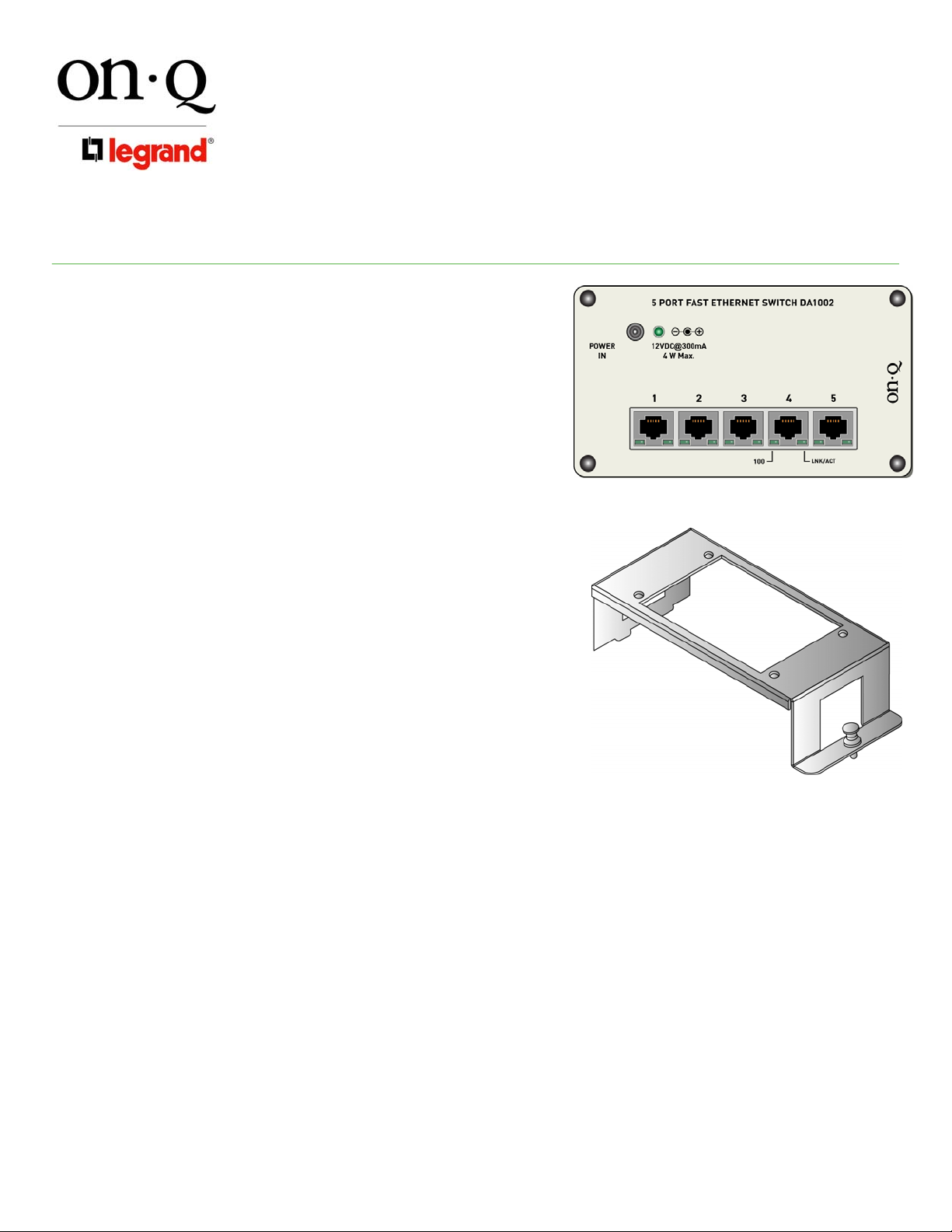
1. INTRODUCTION
The On-Q/Legrand 5-Port Fast Ethernet Switch (P/N DA1002)
supports up to five computer connections in an Ethernet local
area network at a throughput of up to 200 Mbps, and acts as a
high-speed Cat 5e termination point for digital data services (see
Figure 1).
2. DESCRIPTION
The On-Q/Legrand 5 Port Fast Ethernet Switch improves
computer performance by providing dedicated bandwidth to
every user, and offers the following benefits:
• Includes single bay bracket (P/N 364890-01) for mounting
in On-Q style enclosure (see Figure 2)
• Automatically adjusts each port to the highest speed
available; No configuration/service interruptions when
migrating from 10Mbps to 100Mbps
NOTE: The LED on the left below each RJ45 jack will light
to indicate 100Mbps operation. The LED on the right
below each RJ45 indicates a valid Ethernet link and/or
data activity (see Figure 1).
• Multiple switches can be cascaded together using a
standard Cat 5 patch cable
3. POWER REQUIREMENTS
The 5-Port Fast Ethernet Switch's power requirements are:
• Voltage: +12 VDC
• Current: 300 mA
• Power: 4 W Max
• Polarity: Tip (+) Barrel (-)
IS-0394 Rev. O
Figure 1
Figure 2
Note: On-Q/Legrand offers several options for power, which range from a dedicated power cube (F7760)
designed to accommodate one module to power solutions designed to accommodate multiple module
installations.
Please refer to the On-Q/Legrand Catalog or the On-Q/Legrand website (http://www.onqlegrand.com)
for more information.
4. INSTALLATION
A. MOUNT THE SWITCH ONTO THE ENCLOSURE.
1. Pull out the plungers which are located at each corner of the 5-Port Fast Ethernet Switch
2. Insert the module onto the included single bay bracket and depre ss each of the four plungers to secure
the module to the bracket
3. To mount the bracket with module into the enclosure, insert the tabs on the left side of the bracket into
the slots in the enclosure and push the bracket pushpin into the appropriate hole in the enclosure to
secure the bracket (with module) to the enclosure
©Copyright 2007 by On-Q/Legrand All Rights Reserved. Page 1 of 2
Page 2
INSTRUCTION / INSTALLATION SHEET
5-Port Fast Ethernet Switch
301 Fulling Mill Road, Suite G
Middletown, PA 17057
Phone (800) 321-2343 / Fax (717) 702-2546
www.onqlegrand.com
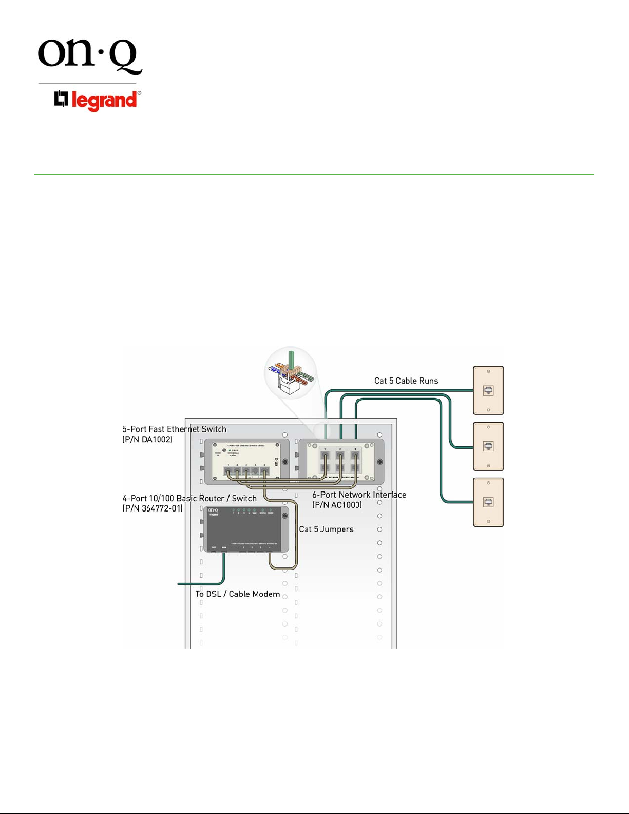
B. TERMINATE WIRING
NOTE: The following example illustrates one use of the 5-Port Fast Ethernet Switch.
1. Terminate each Cat 5e cable run at it's respective wallplate w/RJ45 connector
2. Terminate each Cat 5e cable it's respective connector on the back of the 6-Port Network Interface, as
shown in Figure 3
3. Run Cat 5e jumpers from the Ethernet Switch to the 6-Port Network Interface
4. Run another Cat 5e jumper from a free port on the Ethernet Switch to one of the LAN ports on the Router
5. Connect the Cat 5e cable coming from the DSL/Cable modem to the WAN connection on the Router.
IS-0394 Rev. O
Figure 3
C. APPLY POWER
1. Once all connections have been made, plug the power supply cable into the POWER IN jack on the front
of the 5-Port Fast Ethernet Switch and the supply into an AC outlet.
2. The LED on the front of the 5-Port Fast Ethernet Switch next to the POWER IN jack should light to
indicate power is available. If it does not light, check the AC outlet to insure it is providing power.
©Copyright 2007 by On-Q/Legrand All Rights Reserved. Page 2 of 2
 Loading...