

Page 1

d45 SYSteM
tHe HigH
peRFoRMaNce
AUdio & Video
door entrY
SYSteM
Project And
inStAllAtion
technicAl gUide
the global specialist in door entrY SYSteM
Page 2

Page 3

technical guide
GENERAL FEATURES
GENERAL RULES FOR INSTALLATION
WIRING DIAGRAMS AND VARIANTS
CATALOGUE
TECHNICAL SHEETS
Page 4

Page 5

Contents
GENERAL FEATURES
World presence & Technical assistance . . . . . . . . . . . . . . . . . . . . . . . . . .2
Software . . . . . . . . . . . . . . . . . . . . . . . . . . . . . . . . . . . . . . . . . . . . . 3
Glossary . . . . . . . . . . . . . . . . . . . . . . . . . . . . . . . . . . . . . . . . . . . . . . 5
D45 System introduction . . . . . . . . . . . . . . . . . . . . . . . . . . . . . . . . . . . 6
The main devices . . . . . . . . . . . . . . . . . . . . . . . . . . . . . . . . . . . . . . . . 8
Products list and main features . . . . . . . . . . . . . . . . . . . . . . . . . . . . . . 12
System composition . . . . . . . . . . . . . . . . . . . . . . . . . . . . . . . . . . . . . 13
The configuration . . . . . . . . . . . . . . . . . . . . . . . . . . . . . . . . . . . . . . 22
System functions . . . . . . . . . . . . . . . . . . . . . . . . . . . . . . . . . . . . . . . 23
GENERAL RULES FOR INSTALLATION
System layout . . . . . . . . . . . . . . . . . . . . . . . . . . . . . . . . . . . . . . . . . 30
System cable . . . . . . . . . . . . . . . . . . . . . . . . . . . . . . . . . . . . . . . . . 31
Standard RJ45 connections for CAT5 cable . . . . . . . . . . . . . . . . . . . . . . . 33
RJ45 connections . . . . . . . . . . . . . . . . . . . . . . . . . . . . . . . . . . . . . . . 34
Entrance panels and indoor handsets installation . . . . . . . . . . . . . . . . . . 36
Entrance panel installation . . . . . . . . . . . . . . . . . . . . . . . . . . . . . . . . . 37
Small entrance panel installation . . . . . . . . . . . . . . . . . . . . . . . . . . . . . 38
General configuration concept . . . . . . . . . . . . . . . . . . . . . . . . . . . . . . 39
EP configuration examples . . . . . . . . . . . . . . . . . . . . . . . . . . . . . . . . . 43
Handset configuration examples . . . . . . . . . . . . . . . . . . . . . . . . . . . . . 45
Accessory configuration examples . . . . . . . . . . . . . . . . . . . . . . . . . . . . 47
Lock type and distance limits . . . . . . . . . . . . . . . . . . . . . . . . . . . . . . . 55
Power supply installation rules . . . . . . . . . . . . . . . . . . . . . . . . . . . . . . 57
Power supply check and calculation . . . . . . . . . . . . . . . . . . . . . . . . . . . 62
Maximum system limits . . . . . . . . . . . . . . . . . . . . . . . . . . . . . . . . . . . 67
Troubleshooting . . . . . . . . . . . . . . . . . . . . . . . . . . . . . . . . . . . . . . . 72
WIRING DIAGRAMS
WWW.LEGRAND.COM
Diagram 1 . . . . . . . . . . . . . . . . . . . . . . . . . . . . . . . . . . . . . . . . . . . 76
Handsets riser connection with floor shunt 323002
Diagram 2 . . . . . . . . . . . . . . . . . . . . . . . . . . . . . . . . . . . . . . . . . . . 78
Riser with 2 branches video splitter 323007
Diagram 3 . . . . . . . . . . . . . . . . . . . . . . . . . . . . . . . . . . . . . . . . . . . 80
Backbone system with 1 main entrance panel
Diagram 4 . . . . . . . . . . . . . . . . . . . . . . . . . . . . . . . . . . . . . . . . . . . 82
Backbone system with 1 main entrance panel and porter switchboard 323001
Diagram 5 . . . . . . . . . . . . . . . . . . . . . . . . . . . . . . . . . . . . . . . . . . . 84
System with district generator 323013
Diagram 6 . . . . . . . . . . . . . . . . . . . . . . . . . . . . . . . . . . . . . . . . . . . 86
Riser with lift control interface 323017
Diagram 7 . . . . . . . . . . . . . . . . . . . . . . . . . . . . . . . . . . . . . . . . . . . 88
Town villas system with villa shunt 323016
Diagram 8 . . . . . . . . . . . . . . . . . . . . . . . . . . . . . . . . . . . . . . . . . . . 90
System with D45 interface and fiber optic connection
Diagram 9 . . . . . . . . . . . . . . . . . . . . . . . . . . . . . . . . . . . . . . . . . . . 92
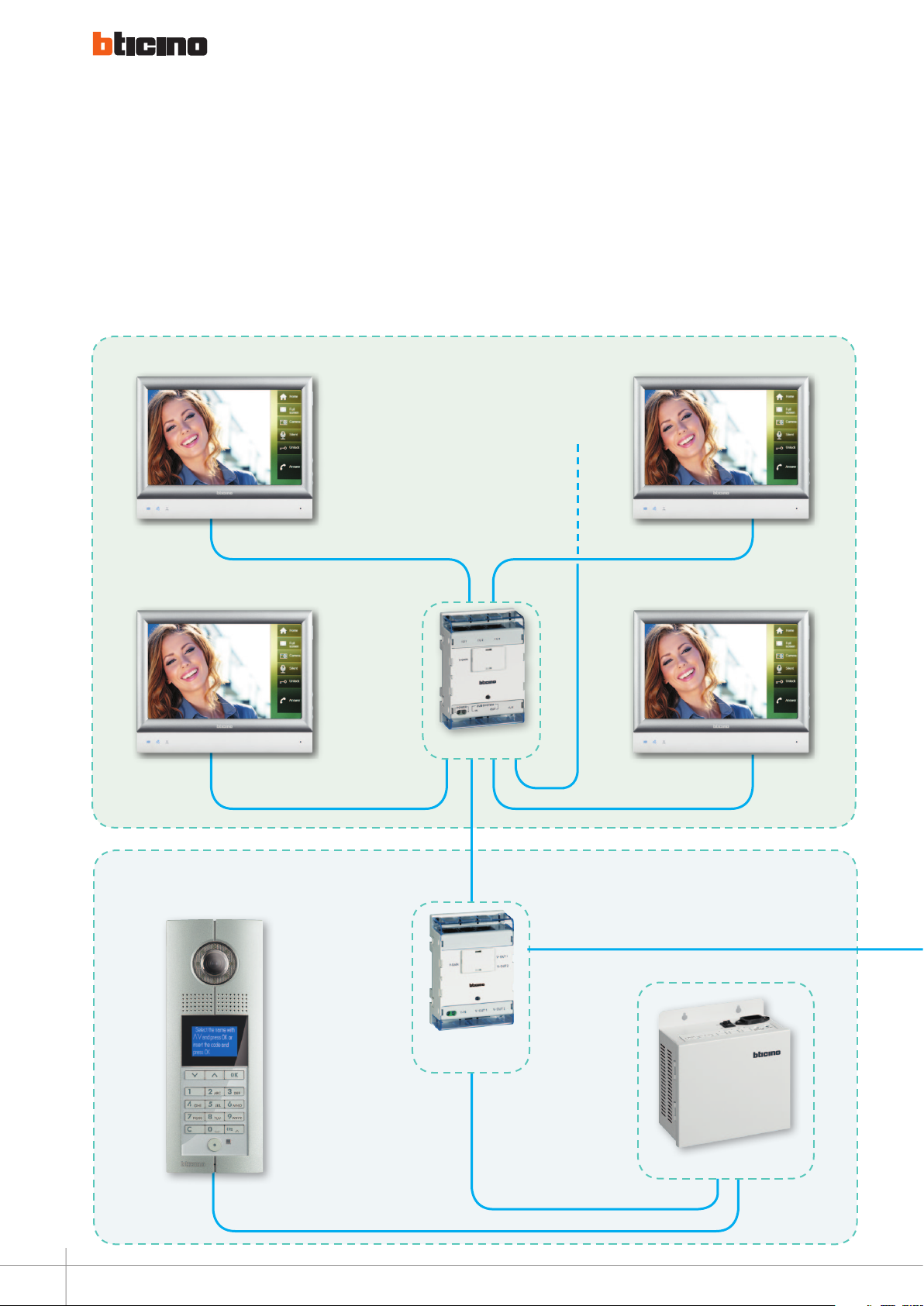
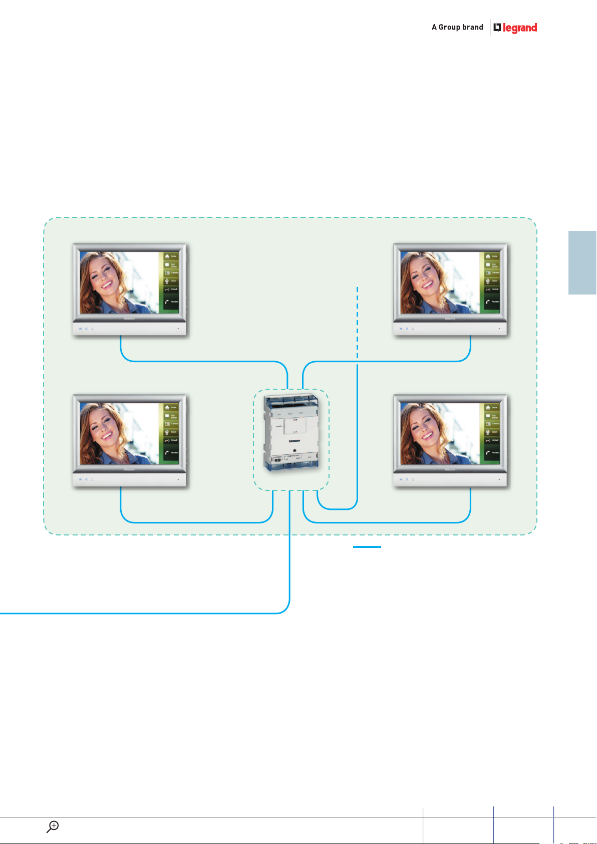
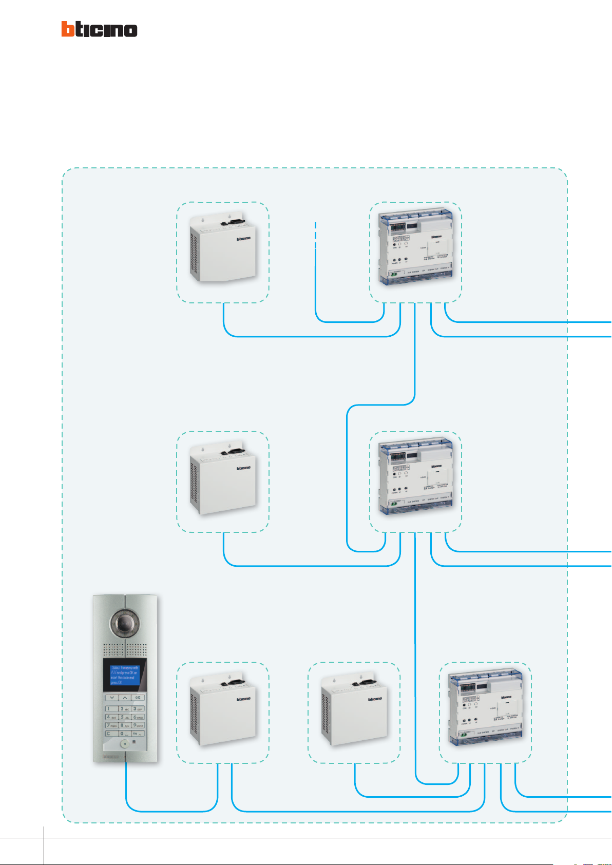
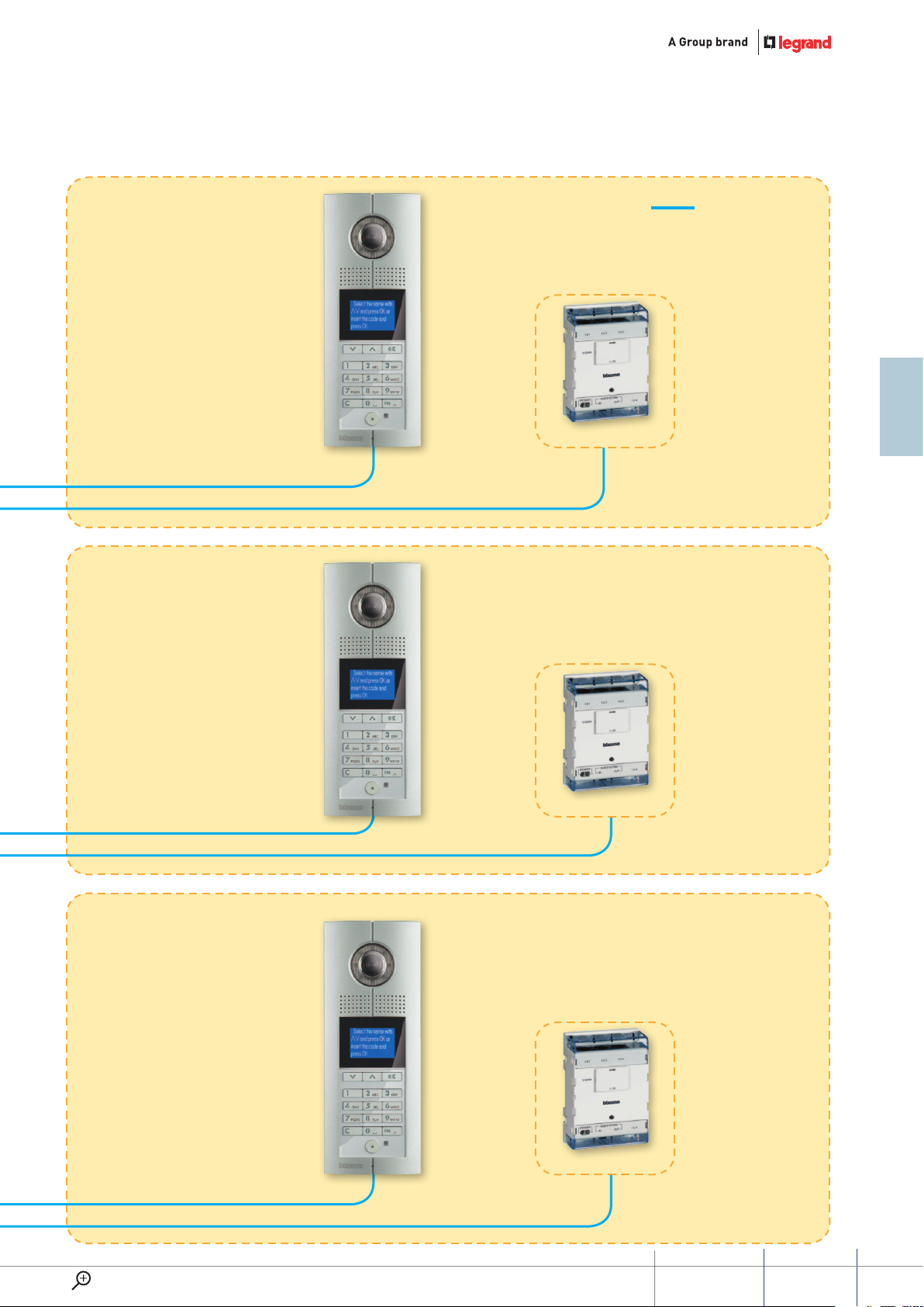
System with D45 interface and software switchboard
D45 SyStem SuMMaRY
Page 6

WIRING DIAGRAMS - VARIANTS
Diagram 1 . . . . . . . . . . . . . . . . . . . . . . . . . . . . . . . . . . . . . . . . . . . 96
IU wired connection + alarm connection
IU rear side connector
Connection way for NC and NO contacts:
Diagram 2 . . . . . . . . . . . . . . . . . . . . . . . . . . . . . . . . . . . . . . . . . . . 98
Basic apartment interface connection
Diagram 3 . . . . . . . . . . . . . . . . . . . . . . . . . . . . . . . . . . . . . . . . . . . 99
D45/2 Wire interface connection
Diagram 4 . . . . . . . . . . . . . . . . . . . . . . . . . . . . . . . . . . . . . . . . . . 100
Apartment interface connection
Diagram 5 . . . . . . . . . . . . . . . . . . . . . . . . . . . . . . . . . . . . . . . . . . 101
Entrance panel video mixer connection
Diagram 6 . . . . . . . . . . . . . . . . . . . . . . . . . . . . . . . . . . . . . . . . . . 102
Wiring diagrams - Door lock relay connection
Diagram 7 . . . . . . . . . . . . . . . . . . . . . . . . . . . . . . . . . . . . . . . . . . 102
Addictional power supply connection
Diagram 8 . . . . . . . . . . . . . . . . . . . . . . . . . . . . . . . . . . . . . . . . . . 103
Entrance pannel auxiliary power supply connection
Diagram 9 . . . . . . . . . . . . . . . . . . . . . . . . . . . . . . . . . . . . . . . . . . 103
Power supply connection for switchboard
Diagram 10 . . . . . . . . . . . . . . . . . . . . . . . . . . . . . . . . . . . . . . . . . . 104
Connection of entrance hall pushbutton to the entrance panel
Diagram 11 . . . . . . . . . . . . . . . . . . . . . . . . . . . . . . . . . . . . . . . . . . 104
Floor call connection
Diagram 12 . . . . . . . . . . . . . . . . . . . . . . . . . . . . . . . . . . . . . . . . . . 104
Back-up battery connection
Diagram 13 . . . . . . . . . . . . . . . . . . . . . . . . . . . . . . . . . . . . . . . . . . 105
IN/OUT connection
Diagram 14 . . . . . . . . . . . . . . . . . . . . . . . . . . . . . . . . . . . . . . . . . . 106
Single family system with more then 1 entry panel
Diagram 15 . . . . . . . . . . . . . . . . . . . . . . . . . . . . . . . . . . . . . . . . . . 107
Single family system with more then 1 indoor unit and more then 1 entry panel
CATALOGUE
Catalogue . . . . . . . . . . . . . . . . . . . . . . . . . . . . . . . . . . . . . . . . . . 110
TECHNICAL SHEETS
The technical sheets . . . . . . . . . . . . . . . . . . . . . . . . . . . . . . . . . . . . 120
Page 7

Numeric index
ITEM CATALOGUE TECHNICAL SHEET ITEM CATALOGUE TECHNICAL SHEET
BT-322010 110 151
BT-322011 110 157
BT-322012 110 167
BT-322030 110 169
BT-322031 110 173
BT-322032 110 177
BT-322033 110 180
BT-322020 110 168
BT-322021 110
BT-322001 110
BT-322002 110
BT-321070 111 141
BT-321071 111 146
BT-322052 111
BT-321061 111
BT-323003 112 198
BT-323004 112 201
BT-323005 112 202
BT-323007 112 208
BT-323008 112 209
BT-323009 112 210
BT-323010 112 214
BT-323011 112 215
BT-323012 113
BT-323013 113 217
BT-323015 113 222
BT-323016 113 225
BT-323021 113
BT-323017 113 228
BT-323018 113 235
BT-322050 111 187
BT-321011 111 129
BT-321060 111 136
BT-322040 111 183
BT-323001 111 194
BT-323002 112 197
BT-323022 112 240
BT-323019 113 238
BT-323020 113 239
BT-323023 113 241
BT-346858 113 248
WWW.LEGRAND.COM
D45 SyStem
SuMMaRY
Page 8

Page 9
GENERAL FEATURES
Page 10

Software and ServiceS
World presence & Technical assistance
World presence web sites in order to find your nearest subsidiaries:
For after sales technical assistance, please refer to the:
www.bticino.com
www.legrand.com
2
Page 11

Software
SOFTWARE FOR QUOTATION AND DESIGN:
YOUDIAGRAM
YouDiagram is the Bticino software
for the quotation and the design of
the entire catalog of digital 2-wire/
D45 and CCTV.
Allows you to draw the diagram of
the system, the choice of the devices,
the configuration of the equipment
and the check of the absorptions.
You can make in a few moments
intercom systems, video entry system
and integrated communication
solution using the product that best
suits your needs.
The design of the system can be
equipped with graphics and notes by
the user and printed directly from the
program and a list of materials and
their configuration.
The print options of the Report
provide integrated PDF.
The outline of the project can be
exported in DXF format.
Free to download from the
www.bticino.com website
www.lEgranD.com
ExamplEs of YouDiagram softwarE scrEEnshots
D45 SyStem
GUIDE
3
Page 12
Software and ServiceS
Software
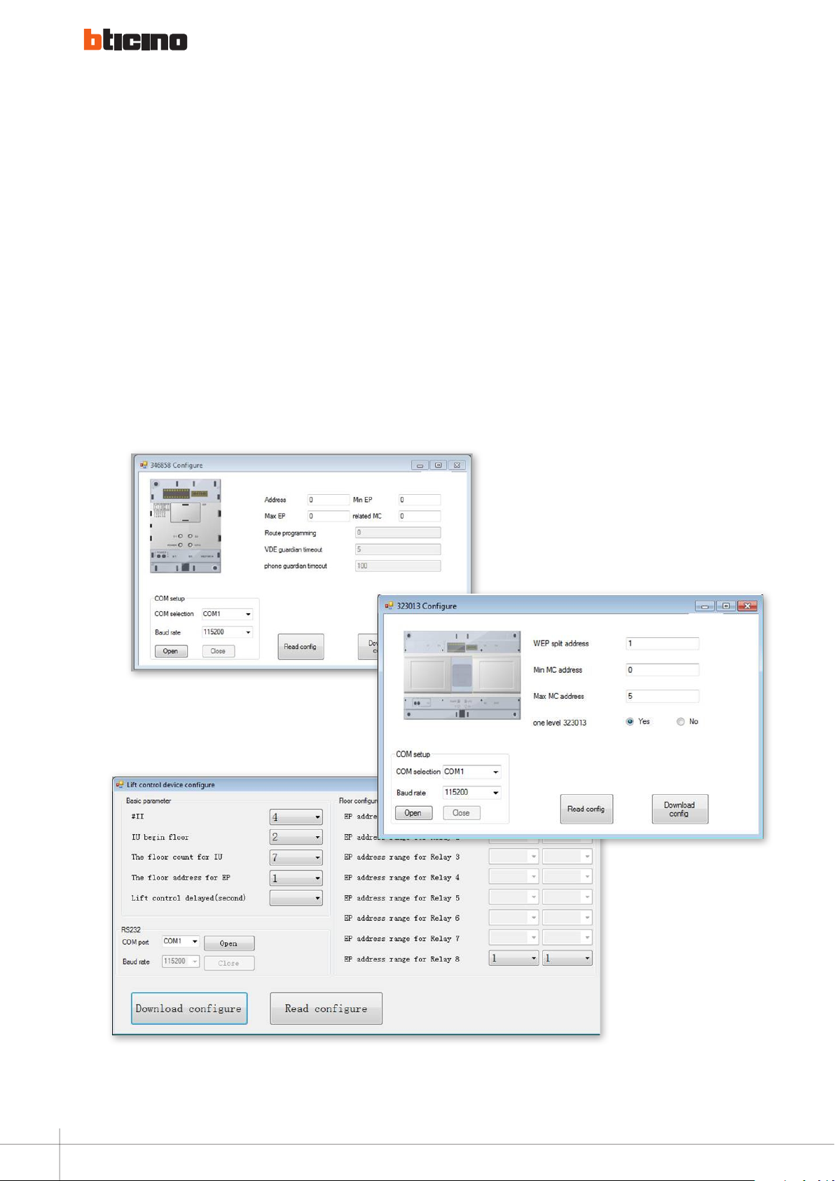
SF2 CONFIGURATION
SOFTWARE
SF2 is the dedicated software
for the configuration and
programming of D45 devices.
The software is supplied within a
configuration tool (323020).
This package consists of the Tool
interface and the Configuration
tool, used by technicians to
download the configuration
information or update programs for
the target devices (EP and interface,
etc.) of the D45 system.
4
Page 13

Glossary
ENTRANCE PANEL
Term used to indicate the device
outside the building, from which the
internal unit can be called.
INTERNAL UNIT
Individual video/audio or audio only
device for the identification of the
individual making the call from the
entrance panel. Normally, in addition
to communicating with the entrance
panel, the internal unit also gives
the possibility of performing other
actions, such as the release of the
door lock, intercom calls, automatic
switching on, etc.
BACKBONE
It provides the connection between
entrance panel and distributes the
signal to.
RISER
It is the set of vertical wiring
connecting the internal units with
the power supply.
FLOOR SHUNT
Hub for the connection of video/
audio and audio only internal units,
apartment interfaces, and additional
power supplies.
OUTSIDE THE DOOR
Set of audio and video devices that
give the possibility of making a call
to the internal unit/s and to identify
the individual making the call. It
is normally installed to make calls
from areas inside the building (hall,
secondary entrances, etc.).
AUTO-SWITCHING ON
Functions providing audio and video
communication between internal
unit and entrance panel, or internal
unit and outside the door unit,
without a call being received.
INTERCOM
Function that provides audio
communication between two
internal units.
MASTER
It is the video internal unit that turns
on when a call is received.
SLAVE
It is the video internal unit connected
in parallel to the master video
internal unit, and which rings but
does not turn on when a call is
received (it only turns on when the
call is answered).
IN / OUT
Connection of the devices where two
clamps act as node between the IN
twisted pair and the OUT twisted pair.
CAT 5E AND CAT 6 CABLE
Data transmission cables made up of
four pairs arranged inside a sheath
according to a specific layout, which
is necessary to reduce attenuation
and crosstalk problems. This layout
consists of twisting the pairs of
conductors individually. These
pairs are identified using standard
colours. Each of the pairs has a
different pitch, and is in turn twisted
differently inside the outer sheath.
The conductor size permitted by
the standards is between 22 and 26
AWG: 24 AWG is the most commonly
used in all cases and corresponds to a
diameter of 0.5 mm.
The acronym AWG (American Wire
Gauge) corresponds to the unit of
measurement used by the American
standards to measure the cross-
sections of cables.
As it is a ratio, the smallest cross-
sections correspond to the largest AWG
sizes. The appropriateness of using
cables with different types of sheath
must be assessed according to the area
in which the wiring system is installed.
The most commonly used cable
sheath is PVC or LSZH (Low
SmokeZero Halogen).
www.lEgranD.com
GUIDED45 SyStEm
5
Page 14
GENERAL FEATURES
D45 System introduction
D45 SYSTEM is the best solution
on the market for large projects
(high rise buildings, compounds of
buildings and villas).
The D45 system can cover applications
at a considerable distance from the
entrance panel and internal unit (up
to 1km) and with a large number of
apartments (up to 4000).
PERFORMANCE:
Up to 4000 apartments.
Long distance: 1km between
entrance panel and internal unit
(no limits with IP integration
on backbone).
Up to 16 security switchboards.
80 entrance panels per system.
The use of UTP cables and RJ45
connections for all the devices
provides quick and easy installation
for both backbone and riser devices.
The system is suitable for the varied
requirements of systems of different
sizes on riser sor TCP/IP networks,
ensuring maximum cost saving.
In term of function D45 guarantees all
SIMPLICITY:
Cable with RJ45 connector.
Easy and intuitive conguration.
INNOVATIVE SECURITY FUNCTIONS:
Alarm fuction integreted on the
internal unit.
SOS pushbutton on all the
indoor devices.
the functionalities typically required
in large applications and brings to
the market some innovative security
functions (e.g. SOS push button and
integration with burglar and technical
alarms) and comfort (lift control and
intercom between apartment).
Discover the main system features.
INTERCOM between all riser
apartments with Switchboard
installed on the backbone.
LIFT control function.
Anti-Tamper function on the
indoor devices.
Switchboard with the possibility of
connecting an additional camera.
3
1
2
1 ENTRANCE PANEL
2 POWER SUPPLY
3 CAT 5E AND CAT 6 CABLES
4 RISER SHUNT
5 FLOOR SHUNT
6 AUDIO AND VIDEO HANDSETS
6
Page 15

FLOOR 1
To floor shunt
floor 2
FLOOR 1
To floor shunt
floor 2
Apartment 2
Apartment 3
6 6
5
6 6
Apartment 2
Apartment 3
6 6
5
6 6
Apartment 1
Apartment 4
Riser 1
Apartment 1
1
4 4
Apartment 4
Riser 2
1
To riser shunt
Riser 3
2
www.lEgranD.com
2
GUIDED45 SyStEm
7
Page 16
GENERAL FEATURES
The main devices
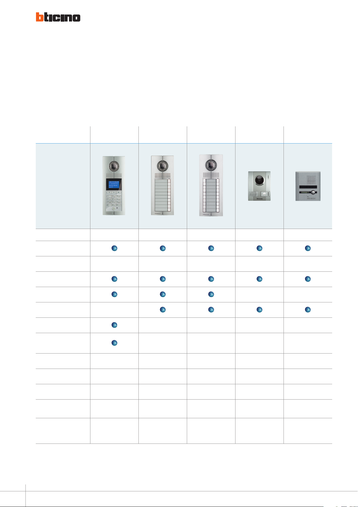
ENTRANCE PANEL
Outdoor video pushbutton panel with camera. It can be used to call the video handsets and to activate the associated door
lock. Available in various look and installation models.
DIgITAL COLOUR
ENTRANCE PANEL
322010 / 322011 322030 322031 322020 322021
Colour video
Finishes / colours Zamak Zamak Zamak Aluminium Plastic
Wall-mounted installation
Flush-mounted installation — —
10 CALL PUShbUTTONS
ENTRANCE PANEL
20 CALL PUShbUTTONS
ENTRANCE PANEL
SMALL ENTRY
PANEL COLOR
FLOOR CALL
ENTRY PANEL
Pushbutton call —
Digital call — — — —
Door lock release with
keypad
Power supply 30 Vdc 30 Vdc 30 Vdc 12 Vdc 12 Vdc
Camera horizontal resolution 540 TV lines 540 TV lines 540 TV lines 420 TV lines 600 TV lines
Protection index IP54 IP54 IP54 IP54 IP33
Protection index against
mechanical impact
Max. number of calls 4000
IK07 IK07 IK07 IK07 IK07
— — — —
10
up to 100 with additional
pushbutton module
up to 100 with additional
20
1 1
pushbutton module
8
Page 17
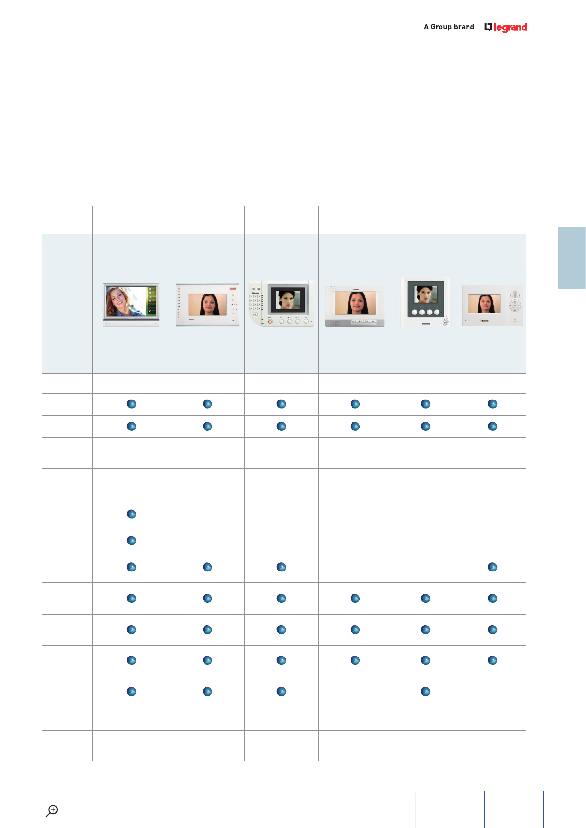
AUDIO AND VIDEO HANDSETS
Audio and video handsets for the audio and video reception of entrance panel calls. Using the available icons, the advanced
devices can be used to manage the video door entry system functions and the home automation functions. Available in
various look and installation models.
Colour video
Handsfree
Finishes /
colours
Display
7" / 10" TOUCh SCREEN
INTERNAL UNIT
321070 / 321071 322050 321011 322052 321060 321061
White nish
metal cover
Touch screen 7" / 10.2”
800 x 480
COLOUR hANDS
FREE 7" AL ARM
White White White White White
7”
480 x 234
COLOUR hANDS
FREE 3.5" ALARM
3.5"
320 x 240
COLOUR hANDS
gREE 7"
480 x 234
COLOUR hANDS
FREE 3.5"
7"
3.5”
320 x 240
COLOUR hANDS
FREE 4.3"
4.3"
Memory
function
SD CARD slot
Alarm
management
SOS function
Door lock
release
Scrolling EP
activation
Intercom — —
Power supply 30 Vdc 30 Vdc 30 Vdc 30 Vdc 30 Vdc 30 Vdc
Type of
installation
Wall mounted Wall mounted Wall mounted Wall mounted Wall mounted Wall mounted
— — — — —
— — — — —
— —
www.lEgranD.com
GUIDED45 SyStEm
9
Page 18
GENERAL FEATURES
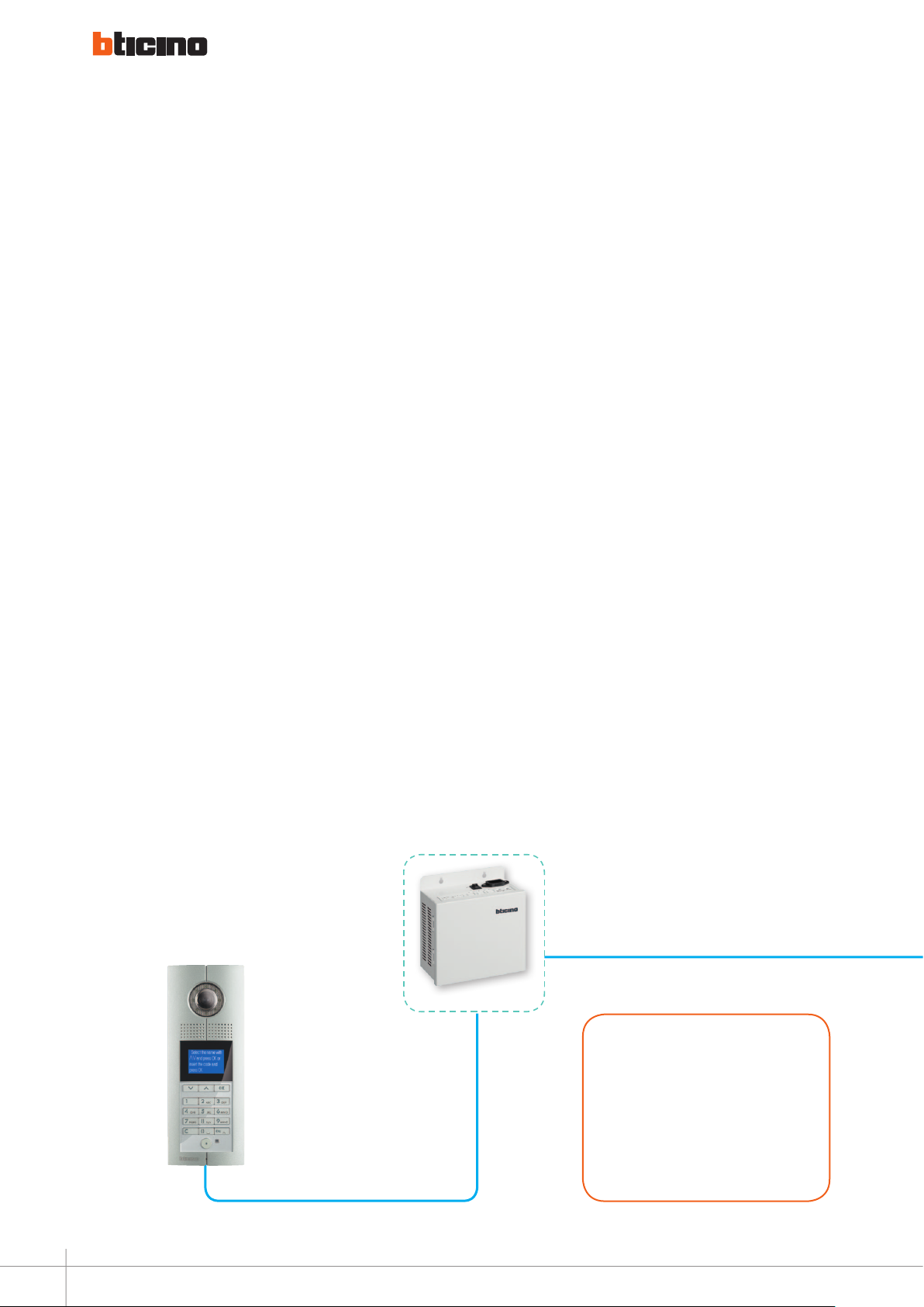
The main devices
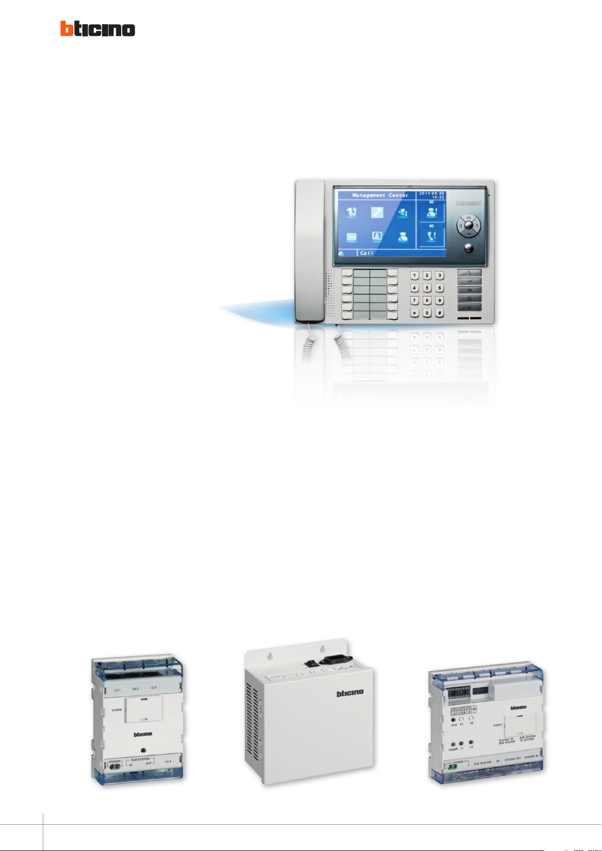
PORTER SWITCHBOARD
This is a table-top device for multi-
family systems, which provides access
to the various apartment complex
video door entry system functions:
intercommunication among
apartments, door lock management,
light switching-on management,
monitoring of cameras installed on
common areas, and monitoring of
apartment alarms.
It has a large 7" colour LCD display
with icon menu, handset, and
handsfree function. It includes the
possibility of creating a handset,
entrance panel, and switchboard
address book.
323001
FLOOR SHUNT
A oor shunt should be installed
between oors. Using a signal cable,
each apartment handset is connected
to the BUS through 323002. One
323002 can be connected to 4
handsets. The device converts the
BUS video signals to transfer mode
and then distributes them to the
connected handsets.
POWER SUPPLY
System power supply unit able
to supply power on the data
communication cable and
simultaneously provide impedance
matching for the audio channel.
Protected against short circuits: in
case of DC output short circuit, the
device will switch to protected mode.
RISER SHUNT
The riser shunt is used to connect the
riser BUS and system BUS in order to
separate BUS, transfer signal and switch
between video and audio channels.
The device has ve Rj45 connectors,
which are for riser BUS input / output,
system BUS input/ output. The last RJ45
and two other connectors are designed
to connect the riser system to the main
power supply.
10
323002
323005
323003
Page 19
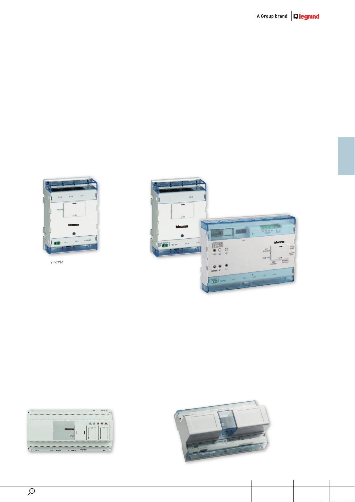
ENTRANCE PANELS
BASIC APARTEMENT INTERFACE
VIDEO MIXER
The entrance panels video mixer
enables connection of up to
5 entrance panels, providing
management of the calls to the riser
(the rst entrance panel from which
the call is made has priority).
323004
APARTEMENT INTERFACE
Basic apartment interface should be installed between Floor shunt and handset.
When one apartment has 2 or 3 handsets, please use this device to extend
interfaces. Apartament interface is installed inside the house of the user and is
used for expanding handsets and Small EP. One Apartment interface can connect
5 handsets and one Small EP, performing the necessary functions for calling the
handsets and calling and monitoring Small EP.
Basic apartment
interface
Apartment
interface
323008
D45/IP INTERFACE
This interface permit to expand the
distances limits of the backbone
and it could be usefull in application
with big distances between entrance
panel and internal unit.
323011
323009
DISTRICT GENERATOR
Is the district hub that can be connected with 4 district riser shunts, 1 wall EP
connector, 1 Switchboard connector and 1 main system power connector. It’s
used to create large networks. Can be connected in cascade to extend to 16
district branches. The maximum level of cascade connection is 1. When installed
as part of the system, the device controls and changes video channel, and
provides amplifying compensation for video signal. The video gains of each Riser
shunt district branch can be set separately.
323013
www.lEgranD.com
GUIDED45 SyStEm
11
Page 20

GENERAL FEATURES
Products list and main features
TYPE MODEL NAME CODE NUMbER FIXINg WAY DIMENSIONS (MM) CURRENT STANDbY AbSORPTION WORK
ENTRANCE
PANNELS
HANDSETS
Digital colour entrance panel 322010 Embedded 325 x 125 x 60,5 30 V / 110 mA 30 V / 290 mA
Entrance panel with call address list 322011 Embedded 325 x 125 x 44,5 30 V / 25 mA 30 V / 245 mA
Small entry panel color 322020 Wall mount 141 x 108 x 31 0 Vdc/ 0 mA 12 V / 250 mA
Floor call entry panel 322021 Wall mount 125 x 104 x 25 0 Vdc/ 0 mA
10 Call pushbuttons entrance panel 322030 Embedded 325 x 125 x 63 30 V / 14 mA 30 V/ 230 mA
20 Call pushbuttons entrance panel 322031 Embedded 325 x 125 x 63 30 V / 14 mA 30 V / 230 mA
3.5" Handsfree internal unit 321011 Wall mount 139,5 x 193,5 x 29 30 V / 20 mA 30 V / 85 mA
3.5" Handsfree internal unit 321060 Wall mount 158 x 165 x 29 30 V / 15 mA 30 V / 85 mA
4,3" Handsfree internal unit 321061 Wall mount 120x179x22.5 30 V / 13 mA 30 V / 90 mA
7" Touch screen internal unit 321070 Wall mount 157 x 198 x 17 30 V / 100 mA 30 V / 200 mA
10" Touch screen internal unit 321071 Wall mount 198 x 255 x 27 30 V / 100 mA 30 V / 200 mA
Audio Internal white 322040 Wall mount 141 x 91 x 34 30 V / 30 mA 30 V / 70 mA
Colour hands free 7" alarm 322050 Wall mount 175 x 260 x 23 30 V / 20 mA 30 V / 145 mA
Colour hands free 7" 322052 Wall mount 155 x 225 x 29 30 Vdc
Porter switchboard 323001 Table 290 x 170 x 165 30 Vdc 30 V / 280 mA
Surface-mounting boxes 1 module 322001
Surface-mounting boxes 2 module 322002
Targa module 322012 Embedded 325 x 125 x 44,5 30 V / 5 mA 30 V / 25 mA
16 Additional pushbuttons panel 322032 Embedded 325 x 125 x 44,5 30 V / 5 mA 30 V / 28 mA
32 Additional pushbuttons panel 322033 Embedded 325 x 125 x 44,5 30 V / 5 mA 30 V / 28 mA
Floor shunt 323002 DIN Rail 72 x 105 x 33 30 V / 25 mA 30 V / 130 mA
Riser shunt 323003 DIN Rail 106 x 105 x 33 30 V / 60 mA 30 V / 110 mA
Entrance panel video mixer 323004 DIN Rail 72 x 105 x 33 30 V / 20 mA 30 V / 60 mA
Power supply 323005 Wall mount 167,5 x 161 x 85 220 V 30 V / 2 A
12
ACCESSORIES
2 Branches video splitter 323007 DIN Rail 72 x 105 x 33 30 V / 25 mA 30 V / 70 mA
Basic apartment interface 323008 DIN Rail 72 x 105 x 33 30 V / 40 mA 30 V / 140 mA
Apartment interface 323009 DIN Rail 141 x 105 x 33 30 V / 40 mA 30 V / 140 mA
Auxiliary power supply 323010 Wall mount 167,5 x 161 x 85 AC input 220 V DC output 30 V / 2 A
D45/IP interface 323011 DIN Rail 90 x 175 x 60 30 V / 130 mA 30 V / 230 mA
SF4 Switchboard software 323012 Laptop Windows
quipped
Distric generator 323013 DIN Rail 175 x 105 x 66 30 V / 100 mA 30 V / 300 mA
Door lock accessory 323015 DIN Rail 72 x 105 x 33 30 V / 30 mA 30 V /30 mA
Villa shunt 323016 DIN Rail 72 x 105 x 33 30 V / 20 mA 30 V / 160 mA
Lift control interface module 323017 DIN Rail 141 x 105 x 33 30 V / 15 mA 30 V / 30 mA
EP/Switchboard shunt 323018 DIN Rail 72 x 105 x 33 30 V / 70 mA 30 V / 70 mA
System expansion interface 323019 DIN Rail 106 x 105 x 33 30 V / 50 mA 30 V / 80 mA
Conguration tool kit 323020 48 x 48
Accessory for additional camera 323021 DIN Rail
Floor shunt with one output module 323022 44 x 30 x 20 30 V / 10 mA 30 V / 80 mA
SEP video mixer 323023 DIN Rail 141 x 105 x 33 30 V / 15 mA 30 V / 1 A
D45/2-wire interface 346858 DIN Rail 72 x 105 x 33 30 V / 1 mA 30 V / 20 mA
Page 21
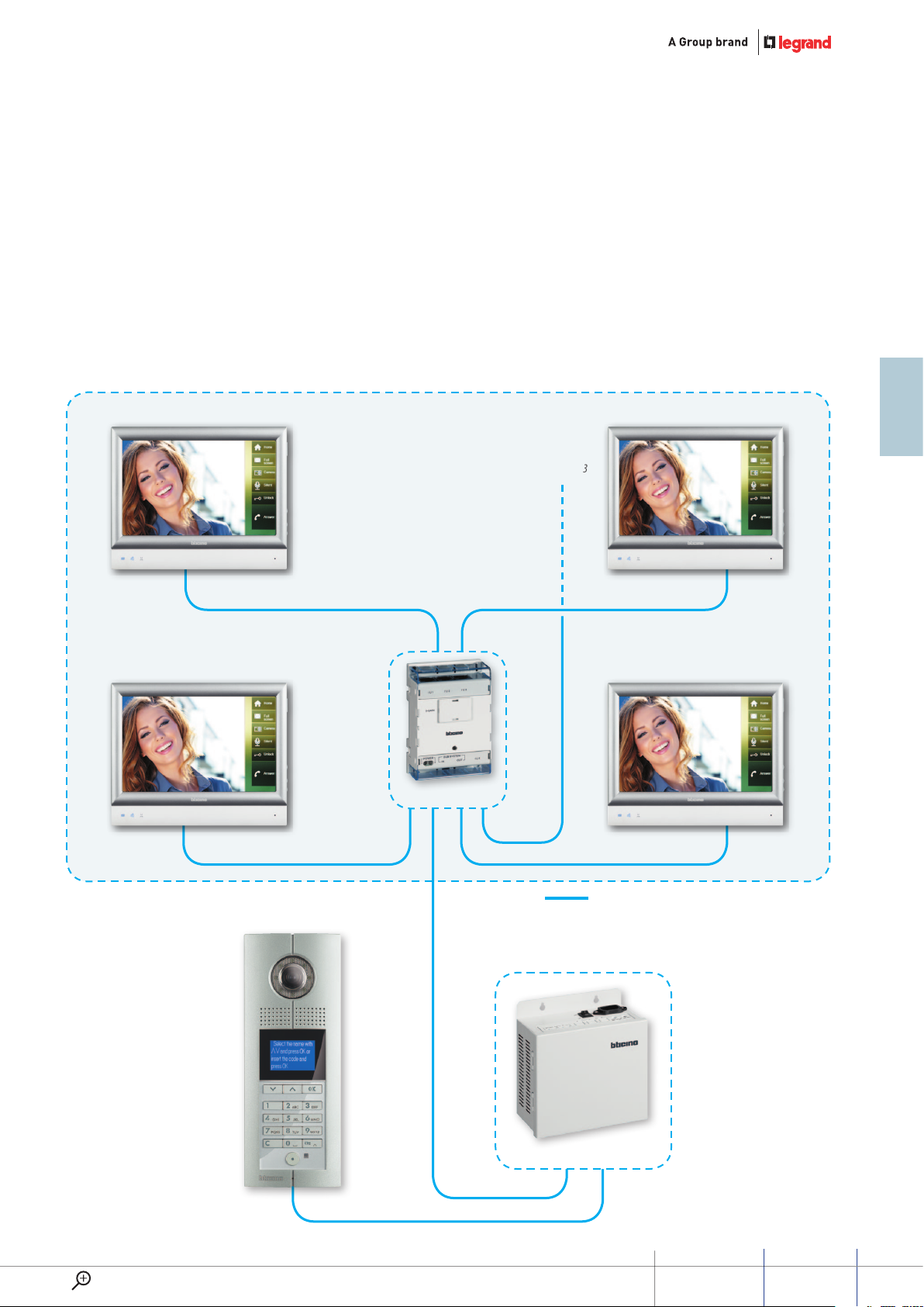
System composition
SINGLE BUILDING WITH ONE RISER
For the installation of one-riser
video systems, the floor shunt,
323002, must be used. It is
particularly suited to multifamily
Apartment 2
Apartment 1
systems with several dwellings on
the same floor, and to multifamily
systems where maximum distance
between entrance panel and
shunt 323003
internal units is required.
The floor shunt provides star
connection of up to 4 apartments.
Apartment 3
To floor
Apartment 4
FLOOR 1
Floor shunt 323002
Connections with RJ45 – Cat 5E/6 cable
Entrance panel
Riser
Power supply 323005
www.lEgranD.com
GUIDED45 SyStEm
13
Page 22
GENERAL FEATURES
System composition
SINGLE BUILDING WITH MORE RISERS
For the installation of video systems
with several branches, the 2-way video
BRANCH 1 FLOOR 1
Apartment 2
Apartment 1
splitter, 323007, and the floor shunts,
323002, can be used.
Apartment 3
To floor
shunt 323003
Apartment 4
Entrance panel
Floor shunt 323002
Riser 1
2-Way Video
Splitter 323007
Power supply 323005
14
Page 23
BRANCH 2 FLOOR 2
Apartment 2
Apartment 1
Apartment 3
To floor
shunt 323003
Apartment 4
Floor shunt 323002
www.lEgranD.com
Riser 2
Connections with RJ45 – Cat 5E/6 cable.
GUIDED45 SyStEm
15
Page 24
GENERAL FEATURES
System composition
APARTMENT BLOCK WITH 1 MAIN ENTRANCE PANEL AND MORE SECONDARY ENTRANCE PANELS
COMMON SYSTEM SECTION
To next
riser shunt
Main entrance panel
Power supply 323005
Power supply 323005
Riser shunt 323003
Riser shunt 323003
16
Power supply 323005 Power supply 323005
Riser shunt 323003
Page 25
BUILDING XX
Riser
entrance panel
Riser XX
Connections with RJ45
Cat 5E/6 cable
Floor shunt 323002
BUILDING 2
BUILDING 1
Riser
entrance panel
Floor shunt 323002
Riser 2
Riser
entrance panel
www.lEgranD.com
Riser 1
Floor shunt 323002
GUIDED45 SyStEm
17
Page 26
GENERAL FEATURES
System composition
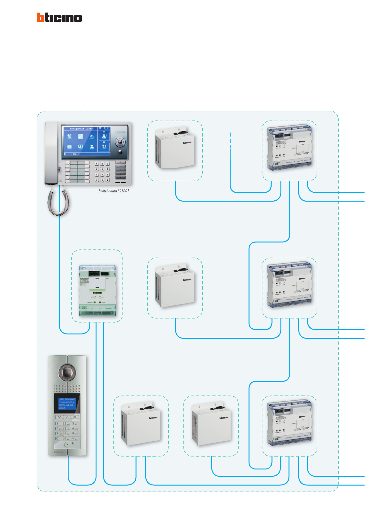
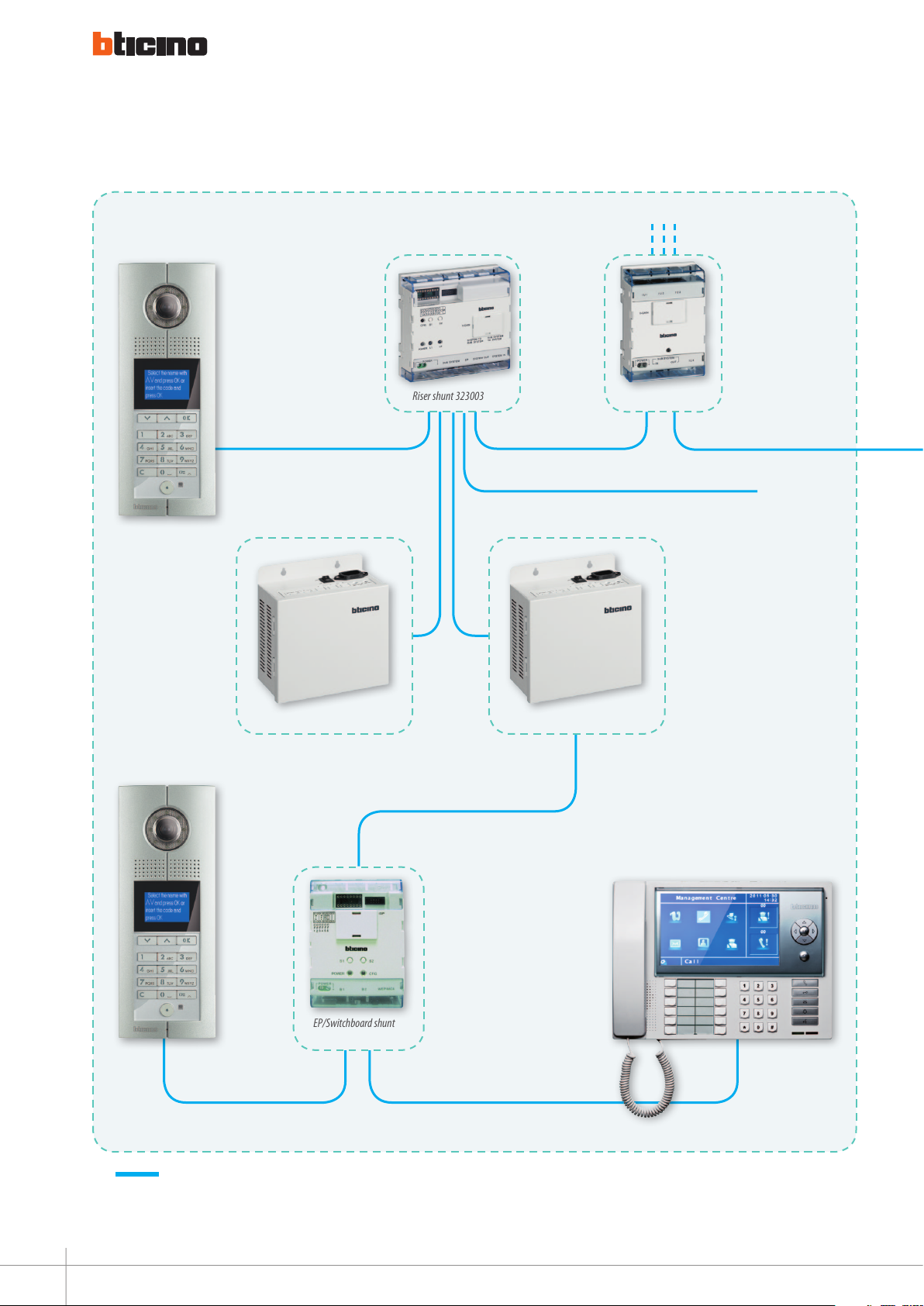
APARTMENT BLOCK WITH 1 MAIN ENTRANCE PANEL, MORE SECONDARY ENTRANCE PANELS AND
SWITCHBOARD
COMMON SYSTEM SECTION
Switchboard 323001
EP/ Switchboard
shunt 323018
Power supply 323005
To next
riser shunt
Riser shunt 323003
Main entrance panel
Power supply 323005
Power supply 323005
Power supply 323005
Power supply 323005
Riser shunt 323003
Riser shunt 323003
18
Page 27

BUILDING XX
Riser
entrance panel
Riser XX
Connections with RJ45
Cat 5E/6 cable
Floor shunt 323002
BUILDING 2
BUILDING 1
Riser
entrance panel
Floor shunt 323002
Riser 2
Riser
entrance panel
www.lEgranD.com
Riser 1
Floor shunt 323002
GUIDED45 SyStEm
19
Page 28
GENERAL FEATURES
System composition
VILLA COMPLEX WITH SWITCHBOARD
Riser entrance
panel
To next floor shunt 323002
Main entrance
panel
Power supply 323005
Riser shunt 323003
Villa shunt 323016
To next riser shunt
323003
Power supply 323005
20
Switchboard 323001
EP/Switchboard shunt
323018
Connections with RJ45 – Cat 5E/6 cable.
Note: - Collegamenti con con cavo Rj45 – Cat 5E/6.
Page 29
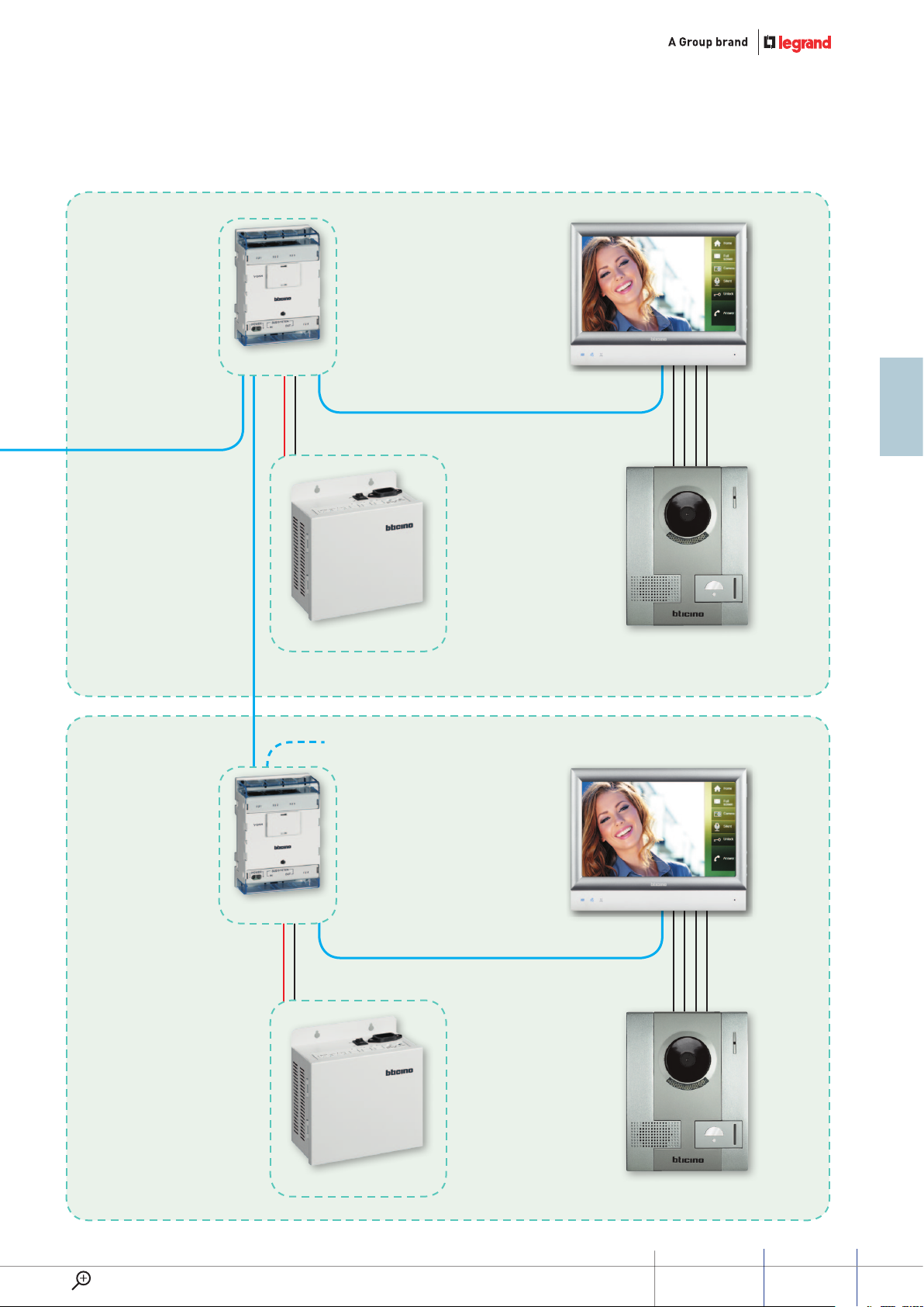
VILLA 1
Touch screen video internal unit
Floor shunt 323002
VILLA 2
Floor shunt 323002
Power supply 323010
To next floor shunt 323002
Small EP 322020
Touch screen video internal unit
www.lEgranD.com
Power supply 323010
Small EP 322020
GUIDED45 SyStEm
21
Page 30
GENERAL FEATURES
The configuration
The configuration assigns a
progressive address to the device
within the system, and programs it
using a simple, quick, and intuitive
Physical configuration
System devices (entrance pannels, handsets and accessories system), must be physically configurated. Insert configurators
with system power supply off.
procedure. D45 system devices may
be configured in two ways:
physical configuration (has priority
over the software configuration);
configuration with SF2 software.
To check the conguration
simply rotate the piece
Configuration with SF2 software
The system component devices (entrance panels, internal units, and system accessories) may be configured in advanced
mode using the PC and an interface (323020 configuration tool). The SF2 configuration and programming software gives the
possibility of completing the configuration and of programming the devices with a high degree of customisation.
Warning: remove the configurators of the devices.
22
Page 31

System functions
Call
The handset rings and the
monitor switches on
THE CALL
Pressing the call pushbutton on the
entrance panel, the system generates
a signal that is only recognised by the
handsets the call is addressed to (the
call will have to be answered within
30 seconds from the moment the
pushbutton is pressed). Each handset
is configured in a unique specific way.
When the call is received, the handset
rings and the monitor switches on.
Press the pushbutton or lift the handset
to establish the communication
(maximum duration of the
communication is 1 minute) with the
entrance panel. Press again or replace
the handset to stop the communication
and switch the monitor off.
Communication
Apartment 2Apartment 1
The conversation cannot
be heard
CONVERSATION SECRECY
During the conversation between
the entrance panel and the video
handsets, all entrance panels and
handsets that are not involved in
the conversation are temporarily
excluded in order to guarantee
the privacy of video door entry
conversations.
When calling from an entrance
panel that is temporarily excluded,
a time-out tone will be heard, to
indicate that the extension line is
momentarily busy.
Call
All the handsets, on the same call,
ring and switch on the monitor
SIMULTANEOUS SWITCHING ON
With video handsets, simultaneous
switching on of the monitor is also
possible: upon arrival of the call,
all handsets ring and the monitors
of all video handsets switch on.
When the call is answered, only
the monitor of the video handset
communicating with the entrance
panel will remain on. In order to set
this function, all the video handsets
but one must be powered locally
using an additional power supply,
323010.
www.lEgranD.com
GUIDED45 SyStEm
23
Page 32

GENERAL FEATURES
System functions
Call
CLAK
Pressing the door lock key will open the gate
associated with the handset.
DOOR LOCK PUSH BUTTON
The handsets are fitted with a door
lock pushbutton. Pressing this
pushbutton will open of one of the
door locks of the system.
With the system at rest, the pressure
of the pushbutton will cause the
opening of the door lock of the
entrance panel associated with the
handset during the P configuration
of the handset itself. On the other
hand, if the pushbutton is pressed
during the call, the door lock
associated to the entrance panel
making the call will be opened.
Each time the self-switching on key is pressed the images
displayed change.
SELF-SWITCHING ON
PUSHBUTTON
By pressing the self-switching on
pushbutton while the videohandset
is at rest, a connection will be
established with the entrance
panel associated with the handset
during the P configuration of
the handset itself. Pressing
repeatedly on the self-switching
on pushbutton, will scroll through
the various entrance panels and the
cameras connected to the system.
Call
Master Slave
When a call is received, the master comes on, while the
SLAVE will only ring.
MASTER-SLAVE FUNCTION
The system offers the MASTER-SLAVE
function: when the call is received,
all the apartment handsets ring,
but only the monitor of the video
handset configured as master comes
on. When the auto-switching on key
of a SLAVE is pressed, the monitor of
the MASTER handset turns off, while
the monitor of the SLAVE itself turns
on (without necessarily establishing
communication with the entrance
panel). If the connection key of
a SLAVE is pressed (or lifting the
handset), the MASTER monitor turns off
and communication with the audio-
video entrance panel is established.
24
Page 33

Apartment 1
We are currently
out....
The person
rings using the
pushbutton
outside the door
INTERCOM
Call
Apartment 2
INTERCOM
The system offers an intercom function,
with up to 3 minutes communications
between videohandsets:
From dierent apartments;
Within the same apartment.
If the apartment has an apartment
interface - or is a one - family
apartment, each videohand set of the
apartment can be called individually.
The INTERCOM connection can be
established at the same time as other
external connections. The INTERCOM
connection can be simultaneous to
other connections external to the
apartment. If the apartment does
not INTERCOM call Apartment 1
Apartment 2 have an apartment
interface any apartment handset can
call all other apartment handsets.
The INTERCOM connection will not
occur at the same time as external
connections. Any call received by an
EP, even to any other apartment, will
terminate the INTERCOM connection.
Answering
machine active
Palyback of sounds and images recorded
by the answering machine
VIDEO DOOR ENTRY SYSTEM
ANSWERING MACHINE
FUNCTION
It is possible to record voice and
images of a call from an entrance
panel. It is also possible to record
an audio message to play back on
the entrance panel following an
unanswered call. The video door
entry system message can be
recorded in 2 ways:
STILLS: the message includes
a picture of the visitor and the
recorded audio message 160
messages max);
VIDEOS: the message includes a
video feed (duration 16 seconds)
and the recorded audio message
(18 messages max). Each message
will be given a progressive number,
which will be displayed on the
video handset, together with the
date and time information.
When the memory is full, the
oldest message is overwritten.
The internal unit operates as a bell for
the call from outside the door.
“FLOOR CALL” FUNCTION
"Call to the Floor" function; by
connecting a pushbutton to the
clamps (R2-R3), it is possible to use
the internal bells of the internal units
for calls from outside the apartment
entrance door. In installations with
internal units connected in parallel.
only the internal unit to which the call
pushbutton is connected will ring.
DOOR LOCK RELEASE FUNCTION
WITH NUMERICAL CODE
Unlock the door lock by inserting a
code in entrance panel.
www.lEgranD.com
GUIDED45 SyStEm
25
Page 34

GENERAL FEATURES
System functions
SOS ALARM
SOS ALARM FUNCTION
This function gives the possibility
of sending a request for help to the
switchboard by pressing a dedicated
SOS key.
An external SOS pushbutton
can be directly connected to the
switchboard.
BATTERY AGAINST BLACK-OUT
The back-up battery is necessary to
power the system in case of power
failure from the mains.
ALARM FUNCTION
This function that enables to have up
to a maximum of 8 alarms (burglar
and technical alarms). The sensors
are connected directly to the internal
unit. When an alarm situation occurs,
if the alarm is not cancelled within
the set time (default 40 seconds),
the message alarm is sent to the
switchboard. When an alarm triggers,
the user can cancel it by using a
password. Once the alarm has been
cancelled, no message is sent to the
switchboard.
ANTI-TAMPER FUNCTION
When the alarm function is set,
a forced action on the internal
unit will trigger the forwarding
of an anti-tamper alarm to the
switchboard. The tamper function
is also set on alarm sensors, to
prevent them from being removed.
26
Page 35

Alarm reception and management
Camera enabling
Intercom calls
SWITCHBOARD
Available for multi-family installations,
the switchboard can be used for
central management and supervision
of the various apartment complex
video door entry system services.
Using this device it is possible to
communicate with the apartment,
manage the door lock, monitor the
cameras connected to the common
areas of the system, and monitor
any alarms from apartments or
common areas. It has a customisable
address book for handsets, entrance
panels, and any other switchboards
connected (max. 16).
Entrance panel call reception
CLAK
Door lock release
LIFT CONTROL
Call the lift at the own floor by
the internal unit before to go out
Avoiding to stand up in front of the
elevator many times in the morning.
Send the lift to the lobby when
someone arrives to visit the client A
good welcome to your friend. When
someone comes to visit, owner of flat
can sent the elevator to the lobby
and automatically send the elevator
to the right floor. The visitor could go
only to the floor of the person that
he knows. Access denied in the other
part of the building to the visitor.
www.lEgranD.com
GUIDED45 SyStEm
27
Page 36

Page 37

GENERAL RULES FOR INSTALLATION
Page 38

GENERAL RULES FOR INSTALLATION
System layout
General features
The first step towards the installation
of a system is to design and ensure a
good basic installation setup. In fact,
an accurate setup of cables, trunking,
boxes, equipment rooms and
control points, gives the possibility
of better following the evolution of
devices already installed inside the
home, and to connect new devices/
expand the system. Irrespective of
the type of system and the required
home automation applications, it
is necessary that the layout of the
house and a general furniture plan,
are made available to the installer.
It is also important to check the
accuracy of the details of the estimate
in relation to the actual site.
In creating a system it will be necessary
to take into account other factors
based on the installation features:
The layout of the conduits;
The type of wiring;
The coexistence of cables inside
the same conduit.
Study
Living room
Kitchen
Hallway
Second
bathroom
Note: having the home layout is of
primary importance for the correct design
and setup of the system.
Bedroom
Bathroom
Children bedroom
30
Page 39

System cable
The D45 system only works correctly if CAT5E and CAT6 original cables are used. Twisted pairs offer good standard and
differential immunity. The CAT5E and CAT6 cables must have a resistance value of 180 ohm/km (for every twisted pair).
BTicino caBle soluTions
Sheath Marking
Cat. 6
U/UTP
100 Ω
Cat. 5E
U/UTP
100 Ω
NOTE: for all other types of cable, please contact the Bticino sales network.
PVC or LSZH cables conforming to standard NFC
32062, ame retardant conforming to standards
IEC 332-1 and NFC 32070 2.1 - Ø 6.4 mm
Colour: RAL 5015 blue
PVC or LSZH cables conforming to standard NFC
32062, ame retardant conforming to standards
IEC 332-1 and NFC 32070 2.1 - Ø 5.2 mm
Colour: RAL 7035 light grey
Bticino (4 pair or 2 x 4 pair) 24 AWG - UTP 100 ohms 250 Mhz
(PVC or LSZH) CAT. 6 250 MHz
EC VERIFIED TO ISO 11801 IEC 332-1 EN 50173-1 TIA/EIA 568A
Batch no. + length in metres
Bticino CAT.NO (4 pair or 2 x 4 pair) 24 AWG UTP 100 ohms
(PVC or LSZH) CAT. 5e EC VERIFIED TO ISO 11801 IEC 332-1 EN
50173-1 TIA/EIA 568A Batch no. + length in metres
Storage
inStallation
teMperature
0 to +50 °C -20 to +60 °C
-15 to +70 °C +5 to +40 °C
operating
teMperature
X/XXX
symmeTrical pair:
Tp = TwisTed pair
shielding of pairs:
u = unscreened
f = foil screened in pairs
exTernal shielding:
u = unshielded,
f = foil screened sheaTh
s = Braided shielding
new ref. old ref. deScription
U/UTP UTP Unshielded twisted multipair cable
F/UTP FTP
U/FTP FTP PIMF
F/FTP FFTP
S/FTP SFTP
Twisted multipair cable
(external foil screen)
Shielded twisted multipair cable
(foil screened in pairs)
Shielded twisted multipair cable
(foil screened in pairs and outer general shielding)
Twisted multipair cable
(foil screened in pairs and outer braid)
WWW.LEGRAND.COM
GUIDED45 SyStEm
31
Page 40

GENERAL RULES FOR INSTALLATION
System cable
caBles used
cat. 5e u/utp caBleS
Category 5E U/UTP unshielded cable with 24AWG (0.51 mm) solid copper conductors, polyolen insulation,
4 pairs of twisted conductors with internal separator - in accordance with ISO/IEC 11801,
and 2.0, EN 50173-1 and EIA/TIA 568 B2.10 standards - grey colour.
U/UTP Sheath Length Packaging
032750
032754
032750 LSZH 305 m box
032751 PVC 305 m box
032873 LSZH 1000 m reel
032874 PVC 1000 m reel
cat. 6 u/utp caBleS
Category 6 U/UTP unshielded cable with 24AWG (0.51 mm) solid copper conductors, polyolen insulation,
4 pairs of twisted conductors with internal separator - in accordance with ISO/IEC 11801,
and 2.0, EN 50173-1 and EIA/TIA 568 B2.10 standards - blue colour.
U/UTP Sheath Length Packagings
032754 LSZH 305 m reel
032871 LSZH 1000 m reel
032872 PVC 1000 m reel
32
Page 41

Standard RJ45 connections for CAT5 cable
87654321
12345678
Pair 1Pair 3
Pair 2
Pair 4
Pair 1Pair 2
Pair 3
Pair 4
T568A
T568B
87654321
12345678
Pair 1Pair 2
Pair 3
Pair 4
T568B
87654321
12345678
Two standards (T568A and T568B) of wires connection, both suitable, although it is recommended that they are not mixed in
the same installation. Table 1 shows the two standards.
Where is Pin #1?
taBle 1
pin t568a t568B Signal
n° pair wire colour pair wire colour
1 3
2 3
3 2
4 1
5 1
6 2
7 4
8 4
2 VIDEO +
2 VIDEO -
3 AUDIO +
1 POWER +
1 POWER -
3 AUDIO -
4 SCS-
4 SCS+
The four pairs are identied with dierent colours and each pair carries a dierent type of signal (see Table 1).
WWW.LEGRAND.COM
GUIDED45 SyStEm
33
Page 42

GENERAL RULES FOR INSTALLATION
RJ45 connections
rJ45 wire Map and connection Method
wire Map 1 2 3 4 5 6 7 8 1~8
Colour White&orange Orange White&green Blue White&blue Green White&brown Brown
SIGNAL Video+ Video- Audio+ Power+ Power– Audio- Data- Data+
Wire specication: CAT cable.
1. Tools for making and testing
CAT5 connections.
Wire crimping tool Tester
2. Steps for making and testing
CAT5 connections.
Step 1: Use the crimping tool to cut
the desired lenght of Cat 5 cable
34
Step 2: remove the outer grey cable
sheath. Use the crimping tool to
cut the wire tips. Place the stripper
on the cable, hold, twist and pull
toward the cable end to strip the
cable sheath off.
Step 3: separate the exposed
coloured strands. Smooth out the
strands and untwist each pair.
Straighten out each wire and put
them in order of colour.
Make sure the cable is free of crimps
and is straightened.
Step 4: after Straightening out each
wire and putting them in colour
order, check the order again. Use the
tip of the crimping tool to cut the
wire tips. You want to cut on a sharp
slant. Otherwise, the difference in
wire length will affect the contact
with the RJ45 connector. If too much
sheath is removed, just cut the bare
wire lengths down as required.
The bare wire length should be 1.5
mm. This length will make it easier to
fit them to the RJ-45 connector.
Page 43

Step 5: hold the RJ-45 connector
between your fingers with the copper
connectors face up. Slide the wires
into the connector, ensuring that
each coloured wire goes into its
matching slot. Push the connector
firmly against the wires.
Step 6: before lock the wires inside
the connector, check from the top of
the connector to see that each wire
is tightly connected to the copper
connector.
Step 7: after the final check, place
the attached RJ-45 connector into
the wire crimping tool. Squeeze the
crimper handles down to lock the
wires in place inside the connector.
When squeezing, a “click” sound
should be heard.
The following picture shows a
correctly fitted connector.
WWW.LEGRAND.COM
Step 8: test the cable.
Connect the two RJ45 connectors to
the tester. Turn on the test. The two
groups of lights will be flashing. If
the 8 lights turn to green one by
one, it means the cable is correctly
assembled. Any red lights or yellow
lights indicate an open circuit or
bad connection.
Two wire cables must be used in the
following conditions:
1. system power supply connection
to floor shunt (323002);
2. addition power supply
connection to Floor shunt;
3. P18V connection to IT1 P18V;
4. EP/ Backbone/main EP
connection to door lock, EP/
Backbone/main EP connection
to door lock and door lock
connection to power supply.
Type DC-loop: 2 x 1.0 mm²
Resistance: 39.4 Ω / 1 km
GUIDED45 SyStEm
35
Page 44

GENERAL RULES FOR INSTALLATION
Entrance panels and indoor handsets installation
small ep/ep/main ep insTallaTion heighT
Below is the recommended installation height for the
entrance panel:
160 – 165 cm
handseT insTallaTion heighT
When installing audio or video internal units, it is advisable
to position the devices as indicated here.
160 – 165 cm
Note: to allow use by disabled people, the device must be installed at a height
of 120-125 cm.
recommendaTion for The insTallaTion
posiTion of The small ep/ep/main ep
The most important condition to observe in the positioning
of cameras is that they must not be turned towards light
source (for example, lamps, sunlight, reflecting surfaces, etc.).
Note: to allow use by disabled people, the device must be installed at a height
of 120-125 cm.
36
Page 45

Entrance panel installation
322010, 322011, 322030, 322032, insTallaTion meThod
Don’t install in hot or damp places
Flush mounted box
Screw
Size overview
125 mm
60.5 mm
325 mm
Flush mounted box
Screw
Rack
1/4
1/4
Install the EP on the door
Note: the flush mounted box must be ordered separately.
Install the EP on the wall
Rack
1/4
1/4
WWW.LEGRAND.COM
GUIDED45 SyStEm
37
Page 46

GENERAL RULES FOR INSTALLATION
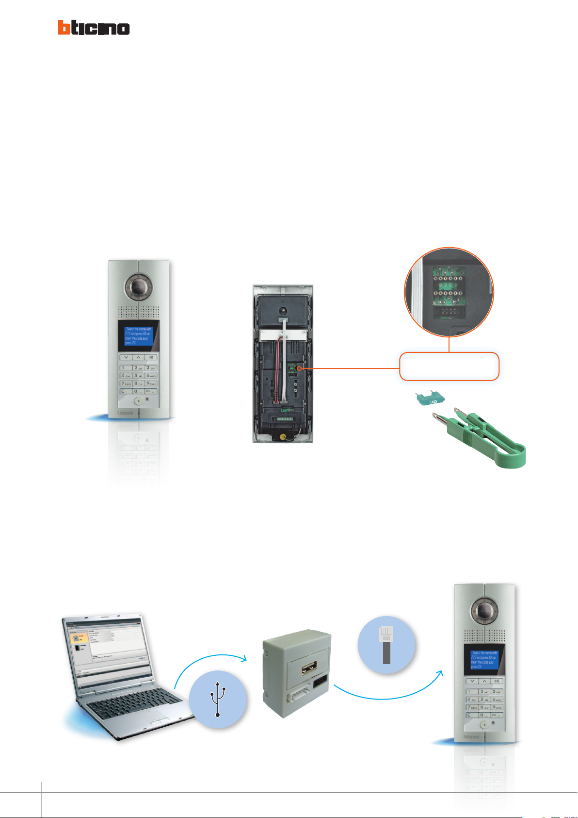
Small entrance panel installation
322020 insTallaTion meThod
30 mm108 mm
> 1.00 m
141 mm
Don’t install in hot or damp places Size overview Installation height and position
≥1.60 m
do noT insTall in hoT or damp places
Installation method 1
Installation instruction:
1. Fix the base to the flush mounted box using the
horizontal holes;
2. connect the cable to EP clamps and fit the cover to the
body using the two grooves on the top;
3. secure the cover in position;
4. tighten up the bottom screw.
> 1.00 m
38
Installation method 2
Installation instructions:
1. Fix the base to the flush mounted box using the
vertical holes;
2. connect the cable to EP clamps and fit the cover to the
body using the two grooves on the top;
3. secure the cover in position;
4. tighten up the bottom screw.
Page 47

General configuration concept
meaning of configuraTion
Address codes are the numbers/
letters used by residents, visitors
and Switchboard operators to
identify the apartments or villas in
the installation. The D45 system
let you use this codes to make calls
within the system. The composition
of address codes follows the rules
below: each handset (apartment
or villa) of the installation must
have one addressing code in order
to be called by visitors and the
Switchboard. The address code of
each apartment depends on the
position within the installation.
Inside the unit/riser each
apartment can be addressed with
a 4 digit code: FFII.
The first two digits refer to the
number of the floor (F F).
The second two digits refer to the
internal number inside the floor: (I I).
The visitor calling the resident from
the unit/riser entrance panel has to
type these codes (push the button
with the code printed on).
Outside the unit/riser each
apartment can be addressed
with a code consisting of 8 digits
maximum: DDDD FFII.
The first four digits can be used in a
flexible way to identify the unit/riser
inside the installation: DDDD may
refer to district/building address or
building/unit address according to
specific installation needs.
In smaller installation less digits can
be used (from 1 to 4).
The other four digits are the same
of the addressing inside the unit/
riser (F F I I).
The visitor calling the resident from
the wall entry panel or the main
Switchboard has to type all the codes
(minimum 5 - maximum 8).
Each digit can be a number from 0
to 9 or a letter from A to J (no mix of
the two in the same digit).
The DDDD address can also be
replaced by meaningful words
(flowers, etc.): in this case the visitor/
user of the Switchboard must find
the right name in the directory.
(Only possible if the building main
entrance panel and the Switchboard
are configured from the PC).
sysTem configuraTion
In order to allow:
Visitors / Switchboards to issue the
calls to the right andset (example
using addressing codes);
residents to issue the call to the
intended Switchboard;
right management of SOS push
buttons, alarms pick up (Identify
the apartment that issued the
alarm, send the alarm to the right
Switchboard);
self-powering of the right building
main EP or secondary EP from
apartment and Switchboard;
some devices of the system must
be congured.
The configuration consists of two
activities:
decide the right numbers to obtain
the intended function (a design/
project activity);
teach to the physical device
its proper conguration (an
installation activity).
Both of these activities can be made
easier by using a PC software – none
of them needs it. As the complexity
of the systems grows (in terms
of topology and/or user function
required) the advantage of using a PC
to perform these activities also grows.
configuraTion design
The configuration of the system is
as close as possible to the address
codes, not worrying installers with
unusual rules. The configuration
method is flexible, and offer two
different configuration procedures:
each configuration procedure can
be applied to different types of
installations (changing their limits/
systems possibilities):
Simplified configuration:
Avoid using the PC;
can only be used if units/riser have
a number of oors and handsets
for each oor set by us during
specication of the “D45”.
WWW.LEGRAND.COM
GUIDED45 SyStEm
39
Page 48

GENERAL RULES FOR INSTALLATION
General configuration concept
Flexible configuration:
A PC can be used (but not
mandatory) to simplify the
installation project (not needed
during the installation);
can be used if units/risers have
a number of oors and handsets
that don’t dier much from one
another. (A table can explain
when an installation can be
congured in this way).
simplified configuraTion
It is compulsory to configure:
1. Audio/video doorphone handsets.
For each handset, its F F I I address
code must be configured, starting
from flat number 1 and from floor
number 1.
2. (Riser shunt). Each riser shunt
must be configured in a
progressive way staring from 1.
If in the entrance panel or
Switchboard the progressive
riser shunt address is used as the
lowest two digits of DDDD, no
configuration of the apartment/villa
to call is needed in the Wall entrance
panel or Switchboard. If the
customer wants a complete DDDD
address to call the apartment/villa,
an association must be performed
on the wall entrance panel and on
the Switchboard between the riser
shunt progressive address and the
DDDD requested by the user.
No PC support is needed/useful for
these activities.
Using this configuration only the
default apartment functions are
available.
With the simple configuration
maximum 4000 apartments can be
installed:
riSer ShuntS
(unit/riSer)
floorS
handSetS/
floor
40 25 4
Alternatively we can have:
16 40 6
25 40 4
22 30 6
20 25 8
or others …].
The simplified configuration can be
applied to a standard installation
or to a district of a multichannel
installation inheriting the limits of the
chosen configuration type.
flexiBle configuraTion
Before configuring the system two
numbers must be decided:
#FF maximum number of floors of
the units/risers of the installation
(a two digit number typical of
the installation– max value 99).
#I I maximum number of
apartments of the floors in the
installation (a two digit number
typical of the installation –
max value 99).
It is compulsory to configure:
1. Audio/video doorphone
handsets. For each handset,
its F F I I address code must
be configured, starting from
flat number 1 and from floor
number 1 and the typical
installation #ii number;
2. riser shunt each riser shunt must
be configured progressively
staring from 1 and the and the
typical installation #ii number;
3. wall entrance panel and
Switchboard. In each wall
entrance panel and Switchboard,
the #FF and #ii installation
numbers must be configured.
If in the entrance panel or
Switchboard the progressive riser
shunt address is used as the lowest
two digits of DDDD, no configuration
of the apartment/villa to call is
needed in the Wall entrance panel or
Switchboard. If the customer want a
complete DDDD address to call the
apartment/villa, an association must
be performed on the wall entrance
panel and on the Switchboard
between the riser shunt progressive
address and the DDDD requested
by the user. Using this configuration
only the default apartment functions
are available.
A PC is not needed to configure the
system on the installation - it can be
used during the project phase to easily
identify and check if it is possible to
configure the system following the
flexible configuration method – it is an
alternative to the table below.
40
Page 49

The flexible configuration can be
used in installation of up to 4000
apartments, with the maximum
limits listed in the linked table (that
can be shared with the people in
charge of the configuration – and can
be completed using how much row
we want to communicate).
The simplified configuration can be
applied to a simplified installation
or to a district of the complete
installation, inheriting the limits of
the chosen configuration type.
nuMBerS
of riSer ShuntS
99 10 4 40
20 50 4 200
11 90 4 360
66 10 6 60
13 50 6 300
7 90 6 540
50 10 8 80
10 50 8 400
5 90 8 720
25 10 16 160
5 50 16 800
12 10 32 320
6 20 32 640
nuMBerS of floorS
# ff
nuMBerS of flatS/floor
#ii
nuMBer of apart. in
each unit/riSer
defaulT Behaviour of
aparTmenT funcTions
The default functions are available
both with simplified and flexible
system configuration.
physical configuraTion
(insTallaTion)
The devices may be configured in
three ways:
Use of physical congurators: this
means placing the right numbered
congurators in the devices in the
right position (depending on the
design of the conguration);
dene a procedure of
conguration of each device that
uses its resources (keypad, LCD,
The default functions are:
Self-powering of the main riser EP;
repeated pression on self power on
function changes on next address
call to Switchboard is to main
Switchboard;
alarm collected by main
Switchboard.
riser EP;
LEDs, etc. ) in order assign to the
device the designated number;
use the PC on the eld to
total nuMBer of apartMentS in the
inStallation:
Number of apt. for each “district”
(AS02: LAN-8Wire interface)
Total number of units/riser for each district 400
Total number of apt./villas for each riser: 800 (if only 1 handset in each apt.)
Total number of apt./villas for each riser: 400 (if only 2 handsets in each apt.)
Total number of apt./villas for each riser: 265 (if only 3 handsets in each apt.)
Total number of apt./villas for each riser: 800 (up to 5 handsets in each apt. with D45 apt. interface)
download the results of the design
conguration done on a PC, on to
each device using its MAC address.
Virtually no liMitS
4.000 apt. or villas.
configuraTion mode for
The whole sysTem
Two configuration modes available,
configuration Mode 1 and
configuration Mode 2. The main
characteristics for each configuration
Mode are described below:
WWW.LEGRAND.COM
*1*: Below are the rules for system configuration (Mode 1).
#ff
for each riSer
≤ 20 ≤4 YES, but it is necessary to calculate the total number of handsets for
> 20 ≤ 4 NO
≤20 > 4 NO
> 20 > 4 NO
#ii
for each floor
can SySteM configuration Mode 1 Be uSed?
whole system according to Mode 1 conguration. If the total number
calculated is 4000 or less, Mode 1 conguration is possible, if the total
number is over 4000, Mode 2 must be considered.
GUIDED45 SyStEm
41
Page 50

GENERAL RULES FOR INSTALLATION
General configuration concept
*2*: Below is an example explaining the rules for system configuration (Mode 2):For example: if the highest building
of a project has 25 floors, and the
max. number of apartment for floor
is 8, with 15 risers in total. Then for
Mode 2, the #FF should be 25, while
#II should be 8. Make the calculations
according to following table to judge
if Mode 2 configuration can be used.
#ff for
each riSer
25 8 15 25*8*15= 3000
#ii for
each floor
total riSer can SySteM configuration Mode 2 Be uSed?
3000< 4000
30 - 25*8*30= 6000
6000> 4000
how To choose The righT
configuraTion mode
The biggest #FF number in the
whole system ≤ 20, the biggest
#II number in the whole system
≤4, and the number of risers ≤ 50:
system conguration Mode 1 is
recommended.
If the biggest #FF number in
whole system is more than 20,
or the biggest #II number is
more than 4, please use system
configuration Mode 1 to set
#FF (choose the biggest #FF
number in the system) and #II
(choose the biggest #II number
in the system), then calculate the
total number of handsets in the
system. If the total number
(#FF * #II * R) is 4000 or less, use
system configuration Mode 2.
sysTem configuraTion
modes
There are 3 possible system
configuration modes:
Resistor conguration;
local keyboard conguration;
conguration using the
conguration software, then
download to the devices using the
RS232 port.
Remarks:
for the 3 above configuration modes, the parameters
to configure are the same, therefore it is not
necessary to describe the configuration procedures
separately. Below is an explanation of the resistor
configuration as an example. The keyboard
configuration is described in the product manual.
The configuration using the RS232 port is described
in the configuration software manual.
device resisTor
configuraTion
42
Page 51

EP configuration examples
322010
digiTal enTrance panel
configuraTion
Possible EP configuration modes
Mode 1 Mode 2
Resistor conguration √ √
Keyboard conguration √ √
RS232 conguration √ √
meaning of each
configuraTor socKeT pin
NN: the number for the main EP, the
number range is from 1 to 80, which
means that the maximum main EP in
riser is 80 (default value: 1).
#FF: typical floors per riser.
#II: typical number of handsets per floor.
N N #F #F #I #I
poSition Mode 1 Mode 2
N
N
Note: the other configuration position C is for
setting the Switchboard address number that will
communicate with the EP directly. The configuration
position C can only be configured using the EP
keyboard or the configuration tool software.
(C default value: 0; this means that the Switchboard
that will communicate with the EP is No.0).
NN Mode 2= Mode 1
#FF is 20 (default).
No need for conguration
#II is 4 (default).
No need for conguration
#FF
(use EP keyboard cong or 323020 download cong)
(use EP keyboard cong or 323020 download cong)
Example (A):
EP address is 5, each riser has 20
floors, and each floor has 4 handset:
system configuration Mode 1 is used.
The Switchboard directly connected
to the main EP is no. 2, main EP
configuration should be as follows:
A
poSition Value for configurator reMarkS
N 0 0
N 5
#F
#F
#I
#I
C 2 This position can use the EP keyboard or the conguration tool for the conguration.
#FF is 20(default).
No need for conguration
#II is 4(default).
No need for conguration
N N #F #F #I #I
0 5
WWW.LEGRAND.COM
GUIDED45 SyStEm
43
Page 52

GENERAL RULES FOR INSTALLATION
EP configuration examples
Example (B):
EP address, each riser has 25 floors,
and each floor has 8 handsets.
System configuration Mode 2 is used.
the Switchboard directly connected
to the main EP is no. 2 MC. Main EP
configuration should be as follows:
B
poSition Value for configurator reMarkS
N 0 It is ok not to insert congurator 0
N 5
#F 2
#F 2
#I 0 It is ok not to insert congurator 0
#I 8
NOTE: there is an additional configuration slot “M”.
M= switchboard address number - can be set only by keyboard or by SF2 software.
N N #F #F #I #I
If configurator or keyboard
configuration is selected for the
main EP, the following conditions
must be met: all 323003 in the
0 5 2 5 0 8
system should be numbered in
sequence. They must start from 1
and no number can be missed.
44
Page 53

Handset configuration examples
321011
possiBle handseT
configuraTion procedure
Mode 1 Mode 2
Resistor conguration
(only for Colour)
Keyboard conguration √ √
RS232 conguration × ×
√ √
meaning of each
configuraTor socKeT pin
FF: Handset floor number.
II: handset household number.
#II: typical number of handsets
per floor.
Congurators position for handsets
poSition
F FF FF
F
I II II
I
#I
#I
Mode 1 Mode 2
Default for #II is 04,
need not connect the congurator
F F I I #I #I
II
(#II setup using same value for all system handsets)
Example (A):
The number of handsets is 1204,
each floor has 4 handsets, the
system configuration Mode is
Mode 1, the handset configuration
should be as follows:
A
poSition configuration Value reMarkS
F 1
F 2
I 0 It is ok not to insert congurator 0
I 4
#I Because the default value of #II is 4, no congurator
#I
is needed
F F I I #I #I
1 2 0 4
WWW.LEGRAND.COM
GUIDED45 SyStEm
45
Page 54

GENERAL RULES FOR INSTALLATION
Handset configuration examples
Example (B):
The number of handsets is 1206,
each floor has 8 handsets. System
configuration Mode 2 is used.
The handset configuration should
be as follows:
B
poSition Value reMarkS
F 1
F 2
I 0 It is ok not to insert congurator 0
I 6
#I 0 It is ok not to insert congurator 0
#I 8
F F I I #I #I
1 2 0 6 0 8
46
Page 55

Accessory configuration examples
323003
riser shunT configuraTion
Possible riser shunt configuration
procedure.
Mode 1 Mode 2
Resistor conguration √ √
Keyboard conguration √ √
Use RS232 conguration × ×
Riser shunt conguration position
meaning of each
configuraTor socKeT pin
NNNN: number of riser shunts.
#FF: typical floor number for riser.
#II: typical number of handsets
for each floor.
#Min handset: the lowest handset.
address managed by this riser shunt.
#Max handset: the highest handset
address managed by this riser shunt.
poSition Mode 1 Mode 2
CF1
CF2
CF3
NNNN NNNN
CF4
CF5
CF6
CF7
CF8
#FF is 20(default).
No need for conguration
#II is 4(default).
No need for conguration
#FF
(#II setup using same value for all system riser shunts)
#II
(#II setup using same value for all system riser shunts)
C C C
M M M
C: the Switchboard number that is
the first priority for this riser.
If the number of the Switchboard
is more than 9 (from 10 to 15), this
parameter can only be set using the
riser shunt keyboard or the SF2.
M: System configuration Mode.
If the selected configuration Mode
is Mode 1 or Mode 2, this parameter
is 0. If this configurator is set using
4
4
SD
SD
3
3
2
2
ON
ON
1
1
number 2, it means that this riser
shunt is only used inside the riser
to extend the maximum number of
handsets (from 400 to 800).
If 323011 is present in the system or
switchboard is install in the riser than
configuration Bit definition reMark
CF11 CF12 First EP number in this riser From 1 to 80
CF13 CF14 Riser EP quantity of riser
CF15 CF16 Riser switchboard number From 1 to 15
CF1 CF2 CF3 CF4 CF5 CF6 CF7 CF8 C M
N N N N #F #F #I #I C M
an additional configuration is needed
for riser shunt as below listed:
configuration can only be set by SF2
software or by keyboard.
WWW.LEGRAND.COM
GUIDED45 SyStEm
47
Page 56

GENERAL RULES FOR INSTALLATION
Accessory configuration examples
Example (A):
The number of riser shunts is 5, each
riser has 20 floors, and each floor has
4 handsets. The Switchboard that can
be called directly by this riser is no. 2.
System configuration Mode 1 is used.
The riser shunt configuration should
be as follows:
A
4
SD
3
2
ON
1
poSition Mode 1 Value for configurator reMarkS
CF1 N 0 0 no cong needed
CF2
CF3
CF4
CF5
CF6
N 0 0 no cong needed
N 0
N 5
#F
#F
CF7 #I #II is 4 (default)
CF8 #I
C C 2
M M 0 0 no cong needed
CF1 CF2 CF3 CF4 CF5 CF6 CF7 CF8 C M
4
SD
3
2
ON
1
N N N N #F #F #I #I C M
0 0 0 5 2 0
0 no cong needed
#FF is 20 (default)
No need for conguration
No need for conguration
Example (B):
The number of riser shunts is 5, each
riser has 25 floors, and each floor has
8 handsets. The Switchboard that
can be called directly by this riser is
no.--># System configuration Mode 2
is used. The riser shunt configuration
should be as follows:
B
4
SD
3
2
ON
1
poSition Mode 1 Value for config. reMarkS
CF1 N 0 It is ok not to insert congurator 0
CF2
CF3
CF4
CF5
CF6
N 0 It is ok not to insert congurator 0
N 0
It is ok not to insert congurator 0
N 5
#F 2
#F 5
CF7 #I 0 It is ok not to insert congurator 0
CF8 #I 8
C C 2 It is ok not to insert congurator 0
M M 0 It is ok not to inser t congurator 0
CF1 CF2 CF3 CF4 CF5 CF6 CF7 CF8 C M
4
SD
3
2
ON
1
N N N N #F #F #I #I C M
0 0 0 5 2 5 2 8 2 0
48
Page 57

323005
power supply configuraTion
Possible configuration way for
power supply
Mode 1 Mode 2
Resistor conguration √ √
Keyboard conguration √ √
RS232 conguration √ √
meaning of each
configuraTor socKeT pin
NNN: Power supply address (range
1–256), only when TYP= 1, the power
supply address will be valid. It means
when TYP= 0, there is no need to
configure NNN.
FF Min: the floor number where this
power management starts from.
FF Max: the floor number where this
power management ends. FF Max
must over or equal to FF Min.
#II: number of apartments on each
floor (at Mode 1, the default number
is 4, no need to set).
#Min handset: the address of the
first address managed by this
configuration Mode 1 (1 pwS for each floor) Mode 2
N
N
N
CF4
CF5
CF6
CF7
CF8
CF9
CF10
CF11
Type Type Type
ASR ASR ASR
M M
LE
power supply).
#Max handset: the last handset
address managed by this
Power supply).
TYP: configuration position for the
power supply function. Used to
enable or disable the power supply
management function and the smart
power function.
NNN
FF Min FF Min
FF Max FF Max
LE LE
power supply will offer to each
handset for the alarm function.
M: position to choose configuration
Mode. connecting configurator 0
means choosing Mode 1 or Mode 2.
LE: configuration position for smart
power supply management. Only
valid when TYP=1. When TYP= 0, no
need to configure that position.
NNN
#II
M
ASR: set how much current the
Congurators position for power supply
WWW.LEGRAND.COM
N N N CF4 CF5 CF6 CF7
N N N
FF
minFFmin
#I #I
CF8 CF9 CF10CF11 TYP ASR M LE
FF
maxFFmax
TYP ASR M LE
GUIDED45 SyStEm
49
Page 58

GENERAL RULES FOR INSTALLATION
Accessory configuration examples
TYP: configuration position for the
power supply function (√means that
this function is available, X means
that this function is not available).
Power supply management:
In the systems with a standby battery
(optional), in case of AC power cut
the handset will automatically enter
energy saving Mode, saving energy for
the alarm function. For systems with
alarm function and standby battery
it is recommended that the power
supply management is kept on.
Smart power supply:
This allows the max quantity of
working small EP when power is
supplied normally. For projects
including small EP, we suggest
that the power supply is used as
auxiliary power supply and that
the smart power supply function
is kept on. When type= 0, no
typ power Supply ManageMent function SMart power function
0 × ×
1 √ √
2 × √
configuration is necessary.
ASR: alarm sinking reserve of each
apartment supplied by the PS.
LE: configuration position for smart
power supply function. This position
controls when to enter energy-saving
Mode under different situations.
aSr = alarM Sinking reSerVe of each apartMent Supplied By the pS
0 300 mA (Default (Max))
1 0 mA
2 50 mA
3 85 mA
4 120 mA
5 150 mA
6 180 mA
7 210 mA
8 240 mA
9 270 mA
0 AC is not an not energy saving
1 AC is not an not energy saving
NOT energy saving: all the system
functions are allowed. This Mode is not
Energy saving. Energy saving: parts of
the system functions (such as video)
are disabled in order to save energy.
50
Page 59

Example (A):
This riser has 20 floors, and each floor
has 4 handsets. This power supply
manages 1-2 floors. If necessary
enable the smart power function and
power management function, the
power supply address is 12, the max
current of the alarm sensor is 300 mA.
System configuration Mode 1 is used.
The power supply configuration
should be as follows:
poSition Mode 1
CF1 N 0
CF2 N 1
CF3 N 2
CF4 FF Min 0
CF5 FF Min 1
CF6 #II
CF7 #II
CF8 FF Max 0
CF9 FF Max 2
CF10 CF10
CF11 CF11
CF12 Type 1
CF13 ASR 0
CF14 M 0
CF15 LE 0
Value for
configurator
reMarkS
Default is 4 apartments.
0 means 4 apartments0.
For Mode 1 and Mode 2, CF10 and CF11
do not apply
A
N N N CF4 CF5 CF6 CF7
N N N
FF
minFFmin
#I #I
0 1 2 0 1
CF8 CF9 CF10CF11 TYP ASR M LE
FF
maxFFmax
TYP ASR M LE
0 2 1 0 0 0
WWW.LEGRAND.COM
GUIDED45 SyStEm
51
Page 60

GENERAL RULES FOR INSTALLATION
Accessory configuration examples
Example (B):
This riser has 20 floors, and each floor
has 5 handsets. This power supply
manages 1-2 floors.
If necessary enable the smart power
function and the power management
function, the power supply address
is 12, max current of the alarm sensor
is 300 mA. System configuration
Mode 2 is used. The power supply
configuration should be as follows:
poSition Mode 1
CF1 N 0
CF2 N 1
CF3 N 2
CF4 FF Min 0
CF5 FF Min 1
CF6 #II 0
CF7 #II 5
CF8 FF Max 0
CF9 FF Max 2
CF10 CF10
CF11 CF11
CF12 Type 1
CF13 ASR 0
CF14 M 0
CF15 LE 0
Value for
configurator
reMarkS
Here conguration is not necessary for
Mode 1 and Mode 2
B
N N N CF4 CF5 CF6 CF7
N N N
FF
minFFmin
#I #I
0 1 2 0 1 0 5
CF8 CF9 CF10CF11 TYP ASR M LE
FF
maxFFmax
TYP ASR M LE
0 2 1 0 0 0
52
Page 61

Example (C):
If necessary enable the smart
power function, no need for the
power management function (if no
management function, the power
supply address does not need
to be set), the range of handset
addresses managed by the power
supply is 125-163.
Without alarm, it means that the
current of alarm sensor is 0 mA. The
system used Mode 3 configuration.
The power supply configuration
should be as follows:
poSition Mode 1
CF1
CF2
CF3
CF4
CF5
CF6
CF7
CF8
CF9
CF10
CF11
CF12
CF13
CF14
CF15
N 0
N 0
N 0
FF Min 0
FF Min 1
#II 2
#II 5
FF Max 0
FF Max 1
CF10 6
CF11 3
Type 2
ASR 1
M 1
LE 0
Value for
configurator
reMarkS
C
N N N CF4 CF5 CF6 CF7
N N N
FF
minFFmin
#I #I
0 0 0 0 1 2 5
CF8 CF9 CF10CF11 TYP ASR M LE
FF
maxFFmax
TYP ASR M LE
0 1 6 3 2 1 1 0
WWW.LEGRAND.COM
GUIDED45 SyStEm
53
Page 62

GENERAL RULES FOR INSTALLATION
Accessory configuration examples
323005 - power supply
configuraTion choosing
The sysTem power soluTion
Solution 1: PWS 323005 will be
chosen as system power supply
inside the riser while auxiliary PWS
(323010) will be chosen for all the
auxiliary power supply.
Suggested power supply solution and related configuration:
Solution 2: PWS 323005 will be
chosen for both system power
supply inside the riser and auxiliary
power supply.
Note: when the system includes Small EP, solution
2 will be helpful to avoid possible damage to the
power supply in the system. When the system has
handsets connected to Small EP, sometimes if several
Small EP call handsets at the same time, a power
supply overload may occur. Under this situation
there is a risk of damage to the power supply.
no. SySteM pwS
Solution
alarM SMall
ep
1 No No 1 X X X X X X
2 No No 1 X X X X X X
3 Ye s No 1 X X X X X X
4 Ye s No 1 NNN X 1 0.2 – 9 1 X
5 No Ye s 2 NNN √ 1 1 0/1 X X √ 2 1 0/1 X
6 No Ye s 2 NNN √ 1 1 0/1 X X √ 2 1 0/1 X
7 Ye s Yes 2 NNN √ 1 0.2~9 0/1 X X √ 2 0.2 – 9 0/1 X
8 Ye s Yes 2 NNN √ 1 0.2~9 0/1 X X √ 2 0.2 – 9 0/1 X
configuration when pwS iS SySteM power Supply
(iMpedance Switch of pwS MuSt Be on)
cf1
cf3
(nnn)
cf4
~
cf11
cf12
~
(type)
cf13
(aSr)
cf14
(M)
cf15
configuration of pwS and auXiliary pwS when pwS
(iMpedance Switch of power Supply MuSt Be off)
cf1
~
(le)
cf3
(nnn)
Here use Auxiliary Power supply, conguration is not necessary.
iS auXiliary power Supply
cf4
cf12
~
cf11
(type)
cf13
(aSr)
cf14
(M)
Note
X: it means no configurator is needed and the configuration position is 0; others need a configurator with corresponding value.√: It means configuration is needed. For the
configuration procedure refer to the system configuration chapter.
cf15
(le)
54
Page 63

Lock type and distance limits
recommended rJ45
connecTor
The actual working environment may
be damp or hot, which can cause
inferior RJ45 connectors to rust.
No need of power for door lock during stand-b, Door lock releaseVoltage: DC12 V, Door lock releaseCurrent: ≤1 A, Time
needed to release the lock (output voltage to release the lock) : ≤100 ms
EP/WEP
L-
We recommend that Legrand/
Ortronics connectors are used
(see specific catalogue).
-L+
EP
WEP
The types of door locks below
are also recommended
(shows diagram as figure 1).
Max distance ≤ 10 m
Cable type 2 x 1.0 mm
2
LOCK
LOCK
If the current required for the door lock is more than 1A (DC12 V), the use of an additional power supply is required instead of
obtaining power from the EP. The connection is shown below:
EP/WEP
L- -L+
ADAPTER
15 V / 2 A
Door lock release
GND
Power
GND
Max distance ≤ 20 m
323015
L+
L-
LOCK
The door lock receives power from
an additional power supply, without
absorbing any current from the EP.
In some cases, other types of door
locks may be used for EPs or main EP.
WWW.LEGRAND.COM
Cable type 2 x 1.0 mm
2
The main characteristic recommended
for door locks are below.
Need power for lock in stand-by.
Stand-by Voltage: DC12.
Maximum stand-by Current: ≤ 0.3 A.
Door lock release method: Stop
powering the door lock.
Time needed to release the lock:
Adjustable.
GUIDED45 SyStEm
55
Page 64

GENERAL RULES FOR INSTALLATION
Lock type and distance limits
For this kind of door lock, an additional power supply must be used. The connection method is shown below.
EP/WEP
L- -L+
Power
supply
The Power supply in the above
drawing is the system riser power
supply. It can be shared by the
riser shunt without the need for an
auxiliary Power supply.
The power supply is the auxiliary
30V
GND
Door lock release
GND
323015
Power
GND
Cable type 2 x 1.0 mm
2
EP power supply (in some cases the
riser has several EP.
In this case auxiliary power supply
will be needed; additional power
supply is also needed if the main EP
cable is too long).
L+
L-
Max distance ≤ 20 mMax distance ≤ 250 m
Cable type 2 x 1.0 mm
LOCK
2
The door lock accessory can be
directly connected to this power
supply without the need for an
additional one.
56
Page 65

Power supply installation rules
There are two kinds of power supplies
for D45 systems, the system and the
auxiliary power supply.
323005 323010
on
off
Can be system
PWS
(when impedance
switch is ON)
Can be auxiliary
PWS
(when impedance
switch is OFF)
Auxiliary
PWS only
Power supply
323005
Comparison between Power supply and Auxiliary Power supply.
function 323005 323010
Set to Be SySteM pwS Set to Be auXiliary pwS auXiliary pwS
Supply power to devices √ √ √
Power supply management
Smart power supply
Supply power to data communication cable √ × ×
Impedance matching √ × ×
From above table, it is found that
the biggest feature of 323005 is that:
it’s capable of supplying power to
the data communication cable, and
offer impedance matching for the
audio channel at the same time.
Therefore, In the project, usually
PWS smart power supply is used as
system power; only when the system
needs auxiliary power supply with
√
(can be on or o)
√
(can be on or o)
Riser shunt:
Where system power supply is
needed: in D45 systems it is possible
to use only 323003, 323019 (able to
extend quantity of handsets inside
riser) and 323009 (able to connect
5 handsets) to separate audio cable
and data communication cable.
In order to supply power to each
data communication cable segment
×
(o )
√
(can be on or o)
×
n/a
×
n/a
and matching audio impedance, it
is necessary to install one (only one
is allowed) system power supply in
each separated area. Other power
supplies must be auxiliary power
supply (323010 or 323005 set as
auxiliary power supply).
Note: 323003 only separate in the direction towards
the riser. Never separate from riser to BUS!
smart function, the PWS will be set as
auxiliary power supply; otherwise, the
auxiliary power supply will be used.
WWW.LEGRAND.COM
GUIDED45 SyStEm
57
Page 66

GENERAL RULES FOR INSTALLATION
Power supply installation rules
legend
One 323005 is needed in the main network area
One 323005 is needed in the green area of the unit
One 323005 is needed in the blue area connected to - 323019
UNIT 2
handset
handset
handset
handset
handset
handset
handset
323002
handset
323019
323005
handset
323002
handset
323005
handset
323002
handset
58
UNIT 1 UNIT 3
323005
Main network line Main network line
323005
323003
EP
During installation of the system, two power supply solutions can be chosen according to different situations.
Page 67

recommended pws soluTion and relaTed configuraTion
no. inStallation
StatuS of SySteM
alarm Small EP
1 none none 1 X X X X X X
2 none none 1 X X X X X X
3 have none 1 X X X X X X
4 have none 1 NNN X 1 0.2~9 1 X
5 none have 2 NNN √ 1 1 0/1 X X √ 2 1 0/1 X
6 none have 2 NNN √ 1 1 0/1 X X √ 2 1 0/1 X
7 have have 2 NNN √ 1 0.2~9 0/1 X X √ 2 0.2~9 0/1 X
8 have have 2 NNN √ 1 0.2~9 0/1 X X √ 2 0.2~9 0/1 X
power
Supply
Solution
configuration when power Supply iS SySteM power Supply
(impedance switch of Power supply must be ON)
CF4
CF12
CF13
CF1
~
CF3
(NNN)
~
CF11
(Type)
(ASR)
CF14
(M)
CF15
(LE)
configuration of power Supply & apower Supply
when Power supply is assistant power supply
(impedance switch of Power supply must be OFF)
CF4
CF12
CF13
(ASR)
CF14
(M)
CF1
~
~
CF11
CF3
(NNN)
Under these four condition, using auxiliary power supply no
(Type)
need congurate
Note:
(X:) It means no configurator is needed and the configuration position is 0; others need a configurator with corresponding value.
(√:) It means configuration is needed. For the configuration procedure refer to the system configuration chapter.
CF1~CF15 is the configuring position for 323005. For the detailed meaning and configuration method please check the system configuration chapter.
CF15
(LE)
connecTion and seTup
procedure for 323005
(Set 323005 as system power supply)
Connector for 323005
WWW.LEGRAND.COM
Difference for each connector
line
colour
power
connection
√
√ √ √ √
√ √ √ √
Video
connection
√ √ √
audio
connection
data
connection
GUIDED45 SyStEm
59
Page 68

GENERAL RULES FOR INSTALLATION
Power supply installation rules
Impedance switch
Power supply
323005
on
off
1) When there is no riser shunt in the system, the system power supply should
be connected and set as following drawing:
OUT
IN
323002 323002EP
POWER
B C A
323005
on
2) When there is riser shunt in the system, the system power supply should be
connected and set as following drawing:
To riser
Backbone
D A
323005
323003
on
Secondary EP
3) When there is no 323013 on
the system BUS, the system
power supply on the BUS should
be connected and set as per the
following drawing:
Backbone Backbone
B C
323005
on on
4) When there is no 323013 on
the system BUS, the system
power supply on the BUS should
be connected and set as per the
following drawing:
323001
BackboneBackbone
From EPS
323013
D A
323005
Backbone
Backbone
on
Secondary EP
5) When there is a Switchboard in the
system, 323001 will get power from
system BUS power supply.
The system BUS power supply should
be connected and set as per the
following drawing:
323001
B C
323005
Backbone
60
Page 69

connecTor for
323005 and 323010
(Set PWS as additional power
supply) or 323010
Connector for 323005 and 323010
1. 323010 doesn’t have and
impedance setting switch, and
can only be used as auxiliary
power supply.
2. if using 323005 as auxiliary
power supply, the impedance
setting switch of 323005 must
be switched to off as per the
following drawing:
Auxiliary
Power supply 323010
on
off
1) the connection of the auxiliary
power supply inside the riser:
To Riser to
next floor shunt
handset
323002
handset
To Riser from previous
floor shunt
D C A
323005
handset
handset
2) When there is a Switchboard in
the system, the Switchboard will get
power from the BUS system auxiliary
power supply. Connection should be
as per the following drawing:
Switchboard
323001
C D
Backbone
323010
WWW.LEGRAND.COM
GUIDED45 SyStEm
61
Page 70

GENERAL RULES FOR INSTALLATION
Power supply check and calculation
Before proceeding to the system installation, it is necessary to check the power supply of the whole system:
1. Check that the power supplies
are enough to supply the power
current needed by the devices to
install the system.
2. Check that the distance (in meters
of cable) between power supply
and devices allows the devices to
get enough power supply voltage
3. Maximum distance between Floor
to work correctly.
Type of handseTs
The video handset can be of different types depending on the power consumption:
type of handSetS
1 2 3 4 5 6 7 8 9 10 11 12
Colour
With alarm
With secondary entrance panel
100 mA current alarm sensor
300 mA current alarm sensor
The maximum quantity of handsets and EP that the riser system power supply can accept:
type of handSetS
1 2 3 4 5 6 7 8 9 10 11 12
shunt and handset Maximum
distance = 50m (CAT5 Cable).
1 EP + Riser shunt
(without A/C)
2 EP + Riser shunt + Entrance panel
+ video mixer (without A/C)
3 EP + Riser shunt + Entrance panel
+ video mixer (without A/C)
4 EP + Riser shunt + Entrance panel
+ video mixer (without A/C)
5 EP + Riser shunt + Entrance panel
+ video mixer (without A/C)
1 EP + Riser shunt
(with A/C)
2 EP + Riser shunt + Entrance panel
+ video mixer (with A/C)
3 EP + Riser shunt + Entrance panel
+ video mixer (with A/C)
4 EP + Riser shunt + Entrance panel
+ video mixer (with A/C)
40 4 12 4 [*1] [*N] 4 [*2] 52 4 12 24 [*1] 4 [*1] 4 [*1]
32 4 8 4 [*1] [*N] 4 [*2] 44 4 12 20 [*1] [*N] 4 [*1]
28 4 4 [*N] [*N] 4 [*2] 38 4 8 12 [*1] [*N] [*N]
24 [*N] 4 [*N] [*N] [*N] 36 4 8 8 [*1] [*N] [*N]
20 [*N] 4 [*N] [*N] [*N] 36 4 4 4 [*1] [*N] [*N]
36 4 8 4 [*1] [*N] 4 [*2] 48 4 12 20 [*1] 4 [*1] 8 [*1]
24 [*N] 4 [*N] [*N] [*N] 36 4 8 8 [*1] [*N] 4 [*1]
16 [*N] 4 [*N] [*N] [*N] 28 [*N] 4 4 [*1] [*N] 4 [*1]
4 [*N] [*N] [*N] [*N] [*N] 16 [*N] 4 [*N] [*N] 4 [*1]
62
5 EP + Riser shunt + Entrance panel
+ video mixer (with A/C)
[*N] [*N] [*N] [*N] [*N] [*N] 4 [*N] [*N] [*N] [*N] [*N]
Page 71

TaBle 1
*N:
in this condition (EPs quantity), the
riser system power supply cannot
provide current to this kind of
handset, an additional power supply
must be used.
The information of table is 5 based on
below condition
1. 50 m cable from Floor shunt
to handset and 5m cable
between floors.
2. 0.5 m cable between Floor shunt
and Floor shunt in same floor for
the projects with more than one
floor shunt on each floor.
3. Between Power supply and 1st
Floor shunt or riser shunt, for the
connection use 2 wire cables.
4. Type of door lock release for EP
is DC12 V/1 A., release time 100
ms or less. The door lock does not
need power during.
*1:
2 small EP and 1 EP can work at the
same time with handsets connected
to the same power supply.
5. When using an entrance panel
video mixer in the riser (more than
one EP in the riser), the distance
between entrance panel video
mixer and riser shunt is 0.5 m.
6. The data listed in above table
are the requirements based on 4
apartments per floor.
For example: if riser use type of
handset, and there is only one EP
without a/C, then we could found
that this system power supply can
afford other 40 handsets except
EP and riser shunt according
*2:
1 small EP and 1 EP can work at the
same time with handsets connected
to the same power supply.
to above table. But these 40
handsets need to be arranged as
4 apartments per floor.
If the height of each floor is 5 m,
the height limit should be applied
at the same time, which means
(40/4- 1)*5= 45 m.
7. If the riser EP get power from
an auxiliary power supply, the
riser system power supply only
provide power to riser shunt, the
floor shunt and the handsets.
WWW.LEGRAND.COM
GUIDED45 SyStEm
63
Page 72

GENERAL RULES FOR INSTALLATION
Power supply check and calculation
Maximum distance between EP or
handset and power supply.
In the riser, the quantity of devices
managed by a power supply are
shown in table 4, table 5, and table 6.
Case 1, case 2, case 3, case 4, case 7,
case 8, case 9 are for 323005(PW1)
and 323010(aPW1). Case 4, case 5,
case 6, case 10, case 11, case 12 are
for 323005(PW1).
Table 4: case 1 to case 4, the quantity of devices managed by 323005 (PW1).
HANDSET
How many apartments
on every oor
2 apartments/oor
(Don’t use extra power cable)
2 apartments/oor
(use extra power cable)
4 apartments/oor
8 apartments/oor
12 apartments/oor
16 apartments/oor
20 apartments/oor
24 apartments/oor
28 apartments/oor
32 apartments/oor
36 apartments/oor
Total Qty of
Case 1 Case 2 Case 3 Case 4
handsets
24 max: 12 oors 4 max: 2 oors 16 max: 8 oors 10 [*1] max: 5 oors
78 max: 39 oors - - 16 max: 8 oors 20 [*1] max: 10 oors
40 max: 10 oors 4 max: 1 oor 16 max: 4 oors 12 [*1] max: 3 oors
56 max: 7 oors 4 max: 1 oor 16 max: 2 oors 12 [*1] max: 2 oors
56 max: 5 oors 4 max: 1 oor 16 max: 2 oors 12 [*1] max: 1 oor
56 max: 4 oors 4 max: 1 oor 16 max: 1 oor 16 [*1] max: 1 oor
68 max: 4 oors 4 max: 1 oor 16 max: 1 oor 20 [*1] max: 1 oor
68 max: 3 oors 4 max: 1 oor 16 max: 1 oor 20 [*1] max: 1 oor
68 max: 3 oors 4 max:1 oor 16 max: 1 oor 20 [*1] max: 1 oor
68 max: 3 oors 4 max:1 oor 16 max: 1 oor 20 [*1] max: 1 oor
68 max: 2 oors 4 max:1 oor 16 max: 1 oor 20 [*1] max: 1 oor
Floor limit
Total Qty of
handsets
Floor limit
Total Qty of
handsets
Notes:
1. The current can also be affected by the distance.
Here every floor is supposed to be 5 m height.
2. If there are many 323002, it is supposed that the
distance of 323002is 0.5 m.
Floor limit
Total Qty of
handsets
Floor limit
64
Table 5: case 1 to case 4, the quantity of devices managed by 323005 (Power supply).
handSet
How many apartments
on every oor
2 apartments/oor
(Don’t use extra power cable)
2 apartments/oor
(use extra power cable)
4 apartments/oor
8 apartments/oor
12 apartments/oor
16 apartments/oor
20 apartments/oor
24 apartments/oor
28 apartments/oor
32 apartments/oor
36 apartments/oor
Total Qty of
Case 5 Case 6 Case 7 Case 8
handsets
4 [*2] max:2 oor 8 [*2] max:4 oor 36 max: 18 oors 8 max: 4 oors
4 [*2] max: 1 oor 8 [*2] max: 1 oor 56 max: 14 oors 8 max: 2 oors
4 [*2] max: 1 oor 8 [*2] max: 1 oor 72 max: 9 oors 8 max: 1 oor
4 [*2] max: 1 oor 8 [*2] max: 1 oor 76 max: 7 oors 8 max: 1 oor
4 [*2] max: 1 oor 8 [*2] max: 1 oor 80 max: 5 oors 8 max: 1 oor
4 [*2] max: 1 oor 8 [*2] max: 1 oor 80 max: 4 oors 8 max: 1 oor
4 [*2] max: 1 oor 8 [*2] max: 1 oor 80 max: 4 oors 8 max: 1 oor
4 [*2] max: 1 oor 8 [*2] max: 1 oor 80 max: 3 oors 8 max: 1 oor
4 [*2] max: 1 oor 8 [*2] max: 1 oor 80 max: 3 oors 8 max: 1 oor
4 [*2] max: 1 oor 8 [*2] max: 1 oor 80 max: 3 oors 8 max: 1 oor
Floor limit
Total Qty of
handsets
8 [*2] max: 4 oors 90 max: 45 oors 8 max: 4 oors
Floor limit
Total Qty of
handsets
Floor limit
Total Qty of
handsets
Floor limit
Page 73

Table 6: case 9 to case 12, the quantity of devices managed by 323005 (Power supply).
handSet
How many apartments
on every oor
2 apartments/oor
(Don’t use extra power cable)
2 apartments/oor
(use extra power cable)
4 apartments/oor
8 apartments/oor
12 apartments/oor
16 apartments/oor
20 apartments/oor
24 apartments/oor
28 apartments/oor
32 apartments/oor
36 apartment/oor
Total Qty of
Case 9 Case 10 Case 11 Case 12
handsets
16 max: 8 oors 16 [*2] max: 16 oors 4 [*3] max: 1 oor 12 [*1] max: 6 oors
16 max: 8 oors 36 [*3] max: 6 oors 4 [*3] max: 1 oor 12 [*1] max: 6 oors
16 max: 4 oors 24 [*3] max: 4 oors 4 [*3] max: 1 oor 12 [*1] max: 3 oors
16 max: 2 oors 32 [*3] max: 3 oors 4 [*3] max: 1 oor 12 [*1] max: 2 oors
16 max: 2 oors 36 [*3] max: 3 oors 4 [*3] max: 1 oor 12 [*1] max: 1 oor
16 max: 1 oor 36 [*3] max: 2 oors 4 [*3] max: 1 oor 12 [*1] max: 1 oor
16 max: 1 oor 36 [*3] max: 2 oors 4 [*3] max: 1 oor 12 [*1] max: 1 oor
16 max: 1 oor 36 [*3] max: 2 oors 4 [*3] max: 1 oor 12 [*1] max: 1 oor
16 max: 1 oor 36 [*3] max: 2 oors 4 [*3] max: 1 oor 12 [*1] max: 1 oor
16 max: 1 oor 36 [*3] max: 2 oors 4 [*3] max: 1 oor 12 [*1] max: 1 oor
16 max: 1 oor 36 [*3] max: 1 oor 4 [*3] max: 1 oor 12 [*1] max:1 oor
Floor limit
Total Qty of
handsets
Floor limit
Total Qty of
handsets
Floor limit
Total Qty of
handsets
Floor limit
*1: 2 small EP and 1 EP can work at the
same time with handsets connected
to the same power supply.
*2: 1 small EP and 1 EP can work at the
same time with handsets connected
to the same power supply.
*3: 3 small EP and 1 EP can work at the
same time with handsets connected
to the same power supply.
The information of table 4 to table 6
is based on the below conditions:
A) 50 m cable from Floor shunt
to handset.
B) 5 m cable between floors.
C) 0.5 m cable between Floor shunt
and Floor shunt in same floor for
the projects with more than one
floor shunt on each floor.
D) Between Power supply and 1st
Floor shunt, for the connection
use 2 wire cables.
E) The data in above table also
limited by distance. Example: 4
apartment on every floor. Case 1.
can have 40 handsetsand the Max.
per floor is 10. In other words, the
distance must less than 45 m,
45 m= [(40/4)-1]*5.
Remark: In table 4, table 5 and table 6 , in case 4, case 5, case 6, case 10, case 11 and case 12, the quantity of handsets is only for 323005.
If using 323010, Please refer to table 7;
WWW.LEGRAND.COM
GUIDED45 SyStEm
65
Page 74

GENERAL RULES FOR INSTALLATION
Power supply check and calculation
Table 7: 323010 application on case 4, case 5, case 6, case 10, case 11 and case 12
How many apartments
on every oor
4 handsets/oor 4 2 3 6 4 5
8 handsets/oor 4 2 3 6 4 5
12 handsets/oor 4 2 3 6 4 5
16 handsets/oor 4 2 3 6 4 5
20 handsets/oor 4 2 3 6 4 5
24 handsets/oor 4 2 3 6 4 5
28 handsets/oor 4 2 3 6 4 5
32 handsets/oor 4 2 3 6 4 5
The information of table 7 is based on
below conditions:
A) 50 m cable from Floor shunt
to handset.
B) 5 m cable between floors.
C) 0.5 m cable between Floor shunt
and Floor shunt in same floor for
projects with more than one floor
shunt on each floor.
D) Between Power supply and 1st
Floor shunt, for the connection use
2 wire cables.
handSet
Case 4 Case 5 Case 6 Case 10 Case 11 Case 12
E) Auxiliary power supply without
smart function.
F) For any types of handsets not listed
in table 7 the information is the
same as table 4 to table 6.
G) For all handsets which connect to
the same auxiliary power supply
the display can be switched on at
the same time.
Remark: if small entrance panels are present, the
number of devices to be supplied by 323010 may
require to use more power supplies, increasing
the project cost.
We therefore suggest to use 323005 to setting
auxiliary power supply.
66
Page 75

Maximum system limits
deVice type MaX. Qty reMarkS
Handsets in the whole system
(Non-IP network system)
Handsets in the whole system
(IP network system)
Handset on each riser 800 323003 can carry 400 handsets at most, but can expand to 800 by connecting 323019 in series in the unit.
EP on each riser 80 EP codes are available, but by expansion using 323004, it is possible to connect 25 EPs in total/80 EP.
4000 The backbone/main EP can call all the handsets.
4000/each
The Backbone/main EP can call 4000 users at most while the Switchboard can call all the users.
IP area, expandable
Backbone/main EP in the whole
80 1, 2, 3…….80/The number of the backbone/main EPs in the whole system must start from 1 and must be
system (Non-IP network system)
Riser shunt in the whole system
100
(Non-IP network system)
Riser shunt in the whole system
(IP network system)
District generator in the whole
100/each
IP area, expandable
5 Using level connection with 5 District generators, it can expand 16 networking branch routes.
system (non IP network system)
Switchboards in the whole system, 16
video limiT disTance
Colour Video limit (EP to HANDSET): 1 Km.
B/W Video limit (EP to HANDSET): 2 Km.
Most of items have the video
frequency expansion function.
The following figure show How to
configure them.
numbered in succession without gaps: 1, 2, 3.......80
entrance panelS
Distance 1 2
0 – 300 m OFF OFF
Colour signal
300 – 700 m ON OFF
700 – 1000 m ON ON
1 2
1 2
1 2
on
off
Note: the instruction data in the above table are
suggestions for the B/W signal.
They may differ during the actual operation.
Irrespective of whether it’s a colour (less than 1000 m)
or B/W signal, please take into account the actual image
when setting the data.
WWW.LEGRAND.COM
riSer Shunt - Video MiXer - diStrict generator
Distance 1 2 3 4
0 – 300 m OFF OFF OFF OFF
Colour signal
300 – 700 m ON OFF OFF OFF
700 – 1000 m ON ON OFF OFF
1000 –1500 m ON ON ON OFF
B/W signal
1500 – 2000 m ON ON ON ON
1 2
1 2
1 2
1 2
1 2
3 4
3 4
3 4
3 4
3 4
GUIDED45 SyStEm
67
Page 76

GENERAL RULES FOR INSTALLATION
Maximum system limits
Example for distance limits:
68
cascade insTallaTion limiTs
of video signal
After being transmitted by multilevel
cascade (insert video amplifier, video
splitter etc in transmission channel), the
video signal will have distortion and
the quality of the image will decrease.
In D45, the maximum level of
cascade is 6.
If any of the following devices is
passed by a video signal in the
system, the cascade level should
increase by 1 level. The total level of
cascade cannot be over 6.
Page 77

colour sysTem - single riser
LINE A
LINE C
Furthest
internal unit
Main power
supply - 323005
LINE B
Floor shunt
323002
Furthest
internal unit
LINE B
Floor shunt
323002
Additional power supply of
floor shunt 323010
LINE A
Power supply
323005
Entrance
panel
Max. distance line A
Furthest internal unit - Power supply
Max. distance line B
Internal unit - Floor shunt
Max. distance line C
Power supply - Entrance panel
WWW.LEGRAND.COM
50 m
50 m
70 m
LINE C
Entrance
panel
Max. distance line A
Furthest internal unit - Entrance panel
Max. distance line B
Internal unit - Power suplly of Floor shunt
Max. distance line C
Power supply - Entrance panel
1 Km
50 m
70 m
GUIDED45 SyStEm
69
Page 78

ON
SD
1
2
3
4
ON
SD
1
2
3
4
GENERAL RULES FOR INSTALLATION
colour sysTem - mulTiple risers
LINE B LINE D
Riser main power suplply
323005
LINE A
Furthest
internal unit
Main power supply
323005
Riser shunt
323003
LINE C
Floor shunt
323002
Max. distance line A
Furthest internal unit - Entrance panel
Max. distance line B
Furthest internal unit - Riser main Power supply
Max. distance line C
Internal unit - Floor shunt
Max. distance line D
Entrance panel - Power supply
1 Km
50 m
50 m
70 m
70
Entrance
panel
Page 79

colour sysTem - mulTiple risers
ON
SD
1
2
3
4
ON
SD
1
2
3
4
LINE B
Additional power supply of
floor shunt 323010
Riser main power suplply
323005
Furthest
internal unit
Floor shunt
323002
Riser shunt
323003
Max. distance line A
Furthest internal unit - Entrance panel
Max. distance line B
Internal unit - Power supply of Flor shunt
Max. distance line C
Entrance panel - Power supply
1 Km
50 m
70 m
LINE A
Main power supply
323005
LINE C
Entrance
panel
WWW.LEGRAND.COM
GUIDED45 SyStEm
71
Page 80

GENERAL RULES FOR INSTALLATION
Troubleshooting
1. The indicators flash when the
handset is called, but there
is no ring.
When the handset being called
does not ring check if it in silent
Mode. If yes, please switch it over
to standard common Mode.
2. The indoor unit is unable to
monitor the entrance panel.
Check whether the first entrance
panel in the riser has been set
as the no 1 entrance panel, and
make sure that the numbers of the
entrance panels in the riser are in
sequence without repetitions.
3. Unable to monitor the Small EP.
The function for monitoring the
small EP can be only used after
installation personnel has set the
system depending on the actual
requirements. If the unit has
been set as a door bell, then the
function for monitoring the gate
EP will be disabled automatically.
4. Double click to turn Small EP
monitoring on.
When starting the small EP
monitor function make sure that
the double click interval is kept
within 800 ms (namely quick
double click on the monitor key),
or it will be considered a request
to monitor the EP.
5. How to make sure that the riser
installation is correct.
Once installing a handset, first
set its number as 101 (default exfactory value). The entrance panel
will now call handset 101.
If the call gets through correctly,
the normal video image will
appears, confirming that the
hardware installation and line
connection are correct (on
adjusting other handset, first
disconnect the first handset at
the 1st floor to avoid having two
handsets with the same address).
In case of more problems, please
check the configuration of
other related devices. Once the
settings have been confirmed, it
is possible to set the handset with
its actual number.
6. When the entry panel calls a
handset with a certain number,
the handset answers but there is
no voice or video signal.
If the entrance panel can call all
handsets with a number smaller
than a certain number (e.g. all
handset with number lower than
501 can be called), these handset
will answer normally. However if a
call is made to a handset with that
number or a higher number, there
is no sound on answering and no
video image is displayed. Now
confirm whether the configuration
on the riser shunt is correct. Take
out the riser shunt from the unit
system and directly connect the
EP to the floor shunt to check if it
works correctly. If it does it means
that the riser shunt is set incorrectly.
7. The entrance panel fails to call a
certain handset.
The handset number may be set
incorrectly, in which case reset
the number and try again. If the
call still fails, set the number as
101 and try again. If it is successful
it may be that the handset
household on each floor is not
the same as the #II setting on the
entrance panel. Reset this again.
If the call still fails, it may be
due to the line or other devices.
Replace the handset and check
the line. The handset will not
answer calls while in installation
setup status. Exit installation
setup status and try again.
8. The entrance panel can call the
handset normally without any
problems.
However, the internal indoor
units can’t be called through and
when answered, they can’t have a
talk.Please make sure that the set
parameters of two indoor units
are identical. if unable to ensure
that, please restore the default
parameters and reset.
9. The Small EP can’t have a
conversation with the handset
and there is no video signal.
Please disable the doorbell
function (this function is
disabled by default).
When the doorbell function is
enabled, and the small EP or the
doorbell calls in, the system will
ring but no conversation will
be possible. This is normal and
ringing will automatically stop
after 10 seconds.
72
Page 81

10. On connecting the Apartment
interface, the handset’s own
number won’t be the same as the
one previously set.
On connecting an apartment
interface, the handset will
automatically detect the
connection and change its own
number to 101. The handset will
automatically use the number set
by the apartment interface.
11. On being powered, the handset
will send the SOS to the
Switchboard.
SOS switch type is different from
the setting type.
Default setting SOS type is NO
(Normally Open).
12. The alarm handset cannot
be armed.
If the alarm handset cannot be
armed, it may be due to the
following:
the probe type is incorrectly set.
For example, the normally closed
type is set as normally open;
the probe is not connected or not
correctly set. First ensure that the
probe is correctly connected to
hardware, and then open software
setup to enable it. There is an
overcurrent on the alarm probe
and it cannot be guarded until
repowered after 10 seconds.
13. The handset is unable to start the
Small EP monitoring function.
IU be set as Slave
Only the master handset can
monitor the Small EP.
IU enable door bell function
If the handset starts the doorbell
function, it will automatically
close down the small EP.
14. The handset is unable to set the
household number
When the handset is connected
with an Apartment interface, the
household number cannot be set.
When the last two digits of the
household number are higher
than the number of users (#II) on
each floor, the household number
cannot be set. For example, if
the handset is programmed for
one-riser two-households on each
floor, then it will be illegal to set
the household number as 203.
15. Some parameters cannot be set.
Some parameter settings in the
handset rely on other parameter
settings, namely they have
an interlocking relation. If the
doorbell function is enabled, Small
EP monitoring cannot start.
When unclear about which
parameter is incorrect, it is
recommended to reset the default
parameters and start again.
Note: after the default parameter has been
restored, all the other parameters will be
restored to the ex-factory value.
16. The alarm indicators or the
zone indicators are always on
irrespective of the status:
This results from the overcurrent
of the alarm probe powered by
the handset which automatically
causes a protection status.
Disconnect the power after 10
seconds to eliminate the fault.
17. When the Small EP calls in, the
handset returns to the idle Mode
immediately:
This is the result of a short-circuit
on the Small EP. Please eliminate
the problem and then reconnect.
18. The secondary EP can call the
handset normally, but when
the main EP calls the handset,
conversation is possible but there
is no video signal.
Make sure that main EP is
connected to system out port of
riser shunt.
WWW.LEGRAND.COM
GUIDED45 SyStEm
73
Page 82

Page 83

WIRING DIAGRAMS
Page 84

WIRING DIAGRAMS
Diagram 1
Handsets riser connection witH floor sHunt 323002
321070 321070
0 2 0 2 0 2 0 3
F F I I #I #I
BUS BUS
A
FLOOR 2FLOOR 1
321070 321070
0 2 0 1 0 2 0 4
F F I I #I #I
1 2
323002
A
321070 321070
0 1 0 2 0 1 0 3
F F I I #I #I
BUS BUS
F F I I #I #I
A
F F I I #I #I
A
BUSBUS
F F I I #I #I
A
A
321070 321070
0 1 0 1 0 1 0 4
F F I I #I #I
1 2
323002
A
A
322011
B
L + +12L – UNLOCK
PBL1
BUS
323005
+
– –
F F I I #I #I
BUSBUS
C
B DCA
+
76
Page 85

To next floor
shunt 323002
321070 321070
x x 0 2 x x 0 3
F F I I #I #I
BUS BUS
FLOOR XX
A
321070 321070
x x 0 1 x x 0 4
F F I I #I #I
1 2
323002
A
A
A
323010
F F I I #I #I
F F I I #I #I
BUSBUS
WARNINGS:
Configure and insert the jumpers with the system
SWITCHED OFF. Also every time the configuration is
modified the pws must be switched OFF and ON again,
waiting about 1 minute.
A To install alternative internal units, refer to
wiring variant section.
B To install alternative Entrance panel, refer to wiring
variant section.
Device configuration by SF2 software.
Set internal IMPEDANCE SWITCH to ON.
C
Auxialiary PWS must be used in relation with the system
D
distance extension - see specific section.
+
+
– –
ITEM DEscrIPTION
322011
Digital call entrance panel
323005 Main power supply
323010 Auxiliar y power suppsly
323002 Floor shunt
321070 7" Touch screen internal unit
L1 Electric door lock 12V - 4A impulsive
PB Door lock release pushbutton
B DCA
D
WWW.LEGRAND.COM
GUIDED45 SyStEm
77
Page 86

321070 321070
321070 321070
WIRING DIAGRAMS
Diagram 2
riser witH 2 brancHes video splitter 323007
321070 321070
A
0 1 0 2 0 8 0 80 1 0 3
F F I I #I #I
BUS BUS
To next floor
shunt 323002
F F I I #I #I
A
323002
321070 321070
0 1 0 1 0 8 0 80 1 0 4
F F I I #I #I
1 2
A
Branch 1
F F I I #I #I
A
323007
1 2 3 4
1 2 3 4
BUSBUS
78
B
L + +12L – UNLOCK
322011
323005
BUS
B DCA
+
+
– –
C
PBL1
Page 87

To next floor
321070 321070
shunt 323002
0 1 0 6 0 8 0 80 1 0 7
F F I I #I #I
A
BUS BUS
323002
F F I I #I #I
A
321070 321070
0 1 0 5 0 8 0 80 1 0 8
F F I I #I #I
1 2
A
Branch 2
F F I I #I #I
A
BUSBUS
WARNINGS:
Configure and insert the jumpers with the system
SWITCHED OFF. Also every time the configuration is
modified the pws must be switched OFF and ON again,
waiting about 1 minute.
A To install alternative internal units, refer to
wiring variant section.
To install alternative Entrance panel, refer to
B
wiring variant section.
Device configuration by SF2 software.
C Set internal IMPEDANCE SWITCH to ON.
WWW.LEGRAND.COM
ITEM DEscrIPTION
322011
Digital call entrance panel
323005 Main power supply
323007 Two branches video splitter
323002 Floor shunt
321070 7" Touch screen internal unit
L1 Electric door lock 12V - 4A impulsive
PB Door lock release pushbutton
GUIDED45 SyStEm
79
Page 88

321070 321070
321070 321070
323003 323003
WIRING DIAGRAMS
Diagram 3
backbone system witH 1 main entrance panel
WARNINGS:
Configure and insert the jumpers with the system
SWITCHED OFF. Also every time the configuration is
modified the pws must be switched OFF and ON again,
waiting about 1 minute.
A To install alternative internal units, refer to
wiring variant section.
To install alternative Entrance panel, refer to
B
wiring variant section.
Device configuration by SF2 software.
C Set internal IMPEDANCE SWITCH to ON.
322011
Auxialiary PWS must be used in relation with the system
D
distance extension - see specific section.
NOTE: see connection variants.
ITEM DEscrIPTION
322011
Digital call entrance panel
323005 Main & Auxiliar y power supply
323003 Riser shunt
323002 Floor shunt
321070 7" Touch screen internal unit
L1 Electric door lock 12V - 4A impulsive
PB Door lock release pushbutton
322011
1
1
BUS
B
Entrance panel
323003
CF4= 1
4
4
SD
SD
3
3
2
2
ON
ON
1
1
Floor shunt 323002
80
B
L + +12L – UNLOCK
323005
C C
323005
BUS
B DCA
+
+
– –
+
– –
B DCA
+
PBL1
Page 89

To next floor
shunt 323002
321070 321070
x x 0 2 x x 0 3
F F I I #I #I
BUS BUS
FLOOR XX
A
321070 321070
x x 0 1 x x 0 4
1 2
323002
A
F F I I #I #I
A
A
F F I I #I #I
F F I I #I #I
BUSBUS
323003 323003
CF4= 2 CF4= 3
4
4
SD
SD
3
3
2
2
ON
ON
1
1
323005
B DCA
+
+
– –
323005
Entrance panel
Floor shunt 323002
4
4
SD
SD
3
3
2
2
ON
ON
1
1
To next riser
shunt 323003
D
– –
B DCA
+
+
WWW.LEGRAND.COM
GUIDED45 SyStEm
81
Page 90

321070 321070
321070 321070
323003 323003
WIRING DIAGRAMS
Diagram 4
backbone system witH 1 main entrance panel and porter switcHboard 323001
WARNINGS:
Configure and insert the jumpers with the system
SWITCHED OFF. Also every time the configuration is
modified the pws must be switched OFF and ON again,
waiting about 1 minute.
A To install alternative internal units, refer to
wiring variant section.
To install alternative Entrance panel, refer to
B
wiring variant section. Device configuration by SF2
software.
C Set internal IMPEDANCE SWITCH to ON.
Auxialiary PWS must be used in relation with the system
D
distance extension - see specific section.
NOTE: see connection variants.
323018
323001
ITEM DEscrIPTION
322011
Digital call entrance panel
323005 Main & Auxiliar y power supply
323003 Riser shunt
323002 Floor shunt
321070 7" Touch screen internal unit
323018 Entrance panel / switchboard shunt
L1 Electric door lock 12V - 4A impulsive
PB Door lock release pushbutton
323001 Porter switchboard
322011
1
B
BUS
322011
BUS
BUS
CF4= 1
323003
C= 1
4
4
SD
SD
3
3
2
2
ON
ON
1
1
Entrance panel
Floor shunt 323002
B
323005
C
B DCA
+
+
– –
323005
– –
B DCA
+
+
82
L + +12L – UNLOCK
PBL1
Page 91

321070 321070
A A
x x 0 2 x x 0 3
To next floor
shunt 323002
F F I I #I #I
BUS BUS
F F I I #I #I
A A
323002
FLOOR XX
321070 321070
x x 0 1 x x 0 4
F F I I #I #I
323003 323003
CF4= 2
C= 1
4
4
SD
SD
3
3
2
2
ON
ON
1
1
1 2
F F I I #I #I
BUSBUS
CF4= 3
C= 1
4
4
SD
SD
3
3
2
2
ON
ON
1
1
Entrance panel
Floor shunt 323002
323005
+
WWW.LEGRAND.COM
– –
To next riser
shunt 323002
323005
B DCA
+
B DCA
+
+
– –
GUIDED45 SyStEm
83
Page 92

WIRING DIAGRAMS
Diagram 5
system witH district generator 323013
Entrance panel
Floor shunt
323002
To next riser
shunt 323003
SD
ON
4
3
2
1
323003
4
SD
3
2
ON
1
Entrance panel
Floor shunt
323002
RISER BLOCK 2
323003
4
4
SD
SD
3
3
2
2
ON
ON
1
1
323001
BUS
323005
+
– –
B DCA
+
RISER BLOCK 1
323005
B DCA
+
+
– –
0 10 1 0 1 0
MC
EPS EPS P/S
MinMCMinMCMaxMCMax
323013
B
84
323010
323005
D C
– –
B DCA
+
+
B DCA
+
+
– –
Page 93

RISER BLOCK 3 RISER BLOCK 4
Entrance panel
Floor shunt
323002
323005
323002
B B
323003
4
4
SD
SD
3
3
2
2
ON
ON
1
1
Entrance panel
323003
4
4
SD
SD
3
3
2
2
ON
ON
1
1
Floor shunt
To next riser
shunt 323003
323005
B DCA
+
+
– –
D D
B DCA
+
+
– –
322011
323010
D B
– –
B DCA
+
+
BUS
L + +12L – UNLOCK
PBL1
WARNINGS:
Configure and insert the jumpers with the system
SWITCHED OFF. Also every time the configuration is
modified the pws must be switched OFF and ON again,
waiting about 1 minute.
A To install alternative internal units, refer to
wiring variant section.
B To install alternative Entrance panel, refer to
wiring variant section.
Device configuration by SF2 software.
Set internal IMPEDANCE SWITCH to ON.
C
Auxiliary PWS must be used in relation with the system
D
distance extension - see specific section.
ITEM DEscrIPTION
322011
Digital call entrance panel
323010 Auxiliar y power supply
323005 Main power supply
303003 Riser shunt
323013 Distric t generator
323001 Porter switchboard
L1 Electric door lock 12V - 4A impulsive
PB Door lock release pushbutton
WWW.LEGRAND.COM
GUIDED45 SyStEm
85
Page 94

WIRING DIAGRAMS
Diagram 6
riser witH lift control interface 323017
Example
Building with 14 floor: 2 to 14 are PRIVATE floors and every floor has 4 apartments. Floor 1 is a PUBLIC floor with one entrance
panel. Delay time set a 10 sec. (CF7= 1). This system needs n° 2 lift control interfaces.
FLOOR 14FLOOR 9
IN
OUT
IN
IN
323002
IU1
1 2
IU2
IU3
IU4
OUTPUT8
323002
IU1
1 2
IU2
IU3
IU4
323002
323017
LIFT CTRL. 2
C
C
C
C
C
C
F
F
F
F
F
F
1
1
2
2
3
3
POWER L1 L2
POWER
-
IN
6
S2S1CFG
OUTPUT2 OUTPUT3 OUTPUT4
OUTPUT1
SYST EM
SYSTEM
+
IN
OUT
323017
OUTPUT5
OUTPUT8 OUTPUT7 OUTPUT6
ISP
C
C
C
C
C
C
C
C
M
M
F
F
F
F
F
F
F
F
7
7
4
5
4
5
6
OUT
0 40 9 6 0 1M1
OUTPUT7
OUTPUT6
OUTPUT5
OUTPUT4
OUTPUT3
OUTPUT2
OUTPUT1
Down key of lift in 14 floor
Down key of lift in 13 floor
Down key of lift in 10 floor
Down key of lift in 19 floor
IU1
1 2
IU2
CF1 CF2 CF3 CF4 CF5 CF6 CF7
IU3
IU4
OUT
86
322011
L + +12L – UNLOCK
322011
B B
323003
4
4
SD
SD
3
3
2
2
ON
ON
1
1
BUS
BUS
To next riser
shunt 323003
323005
323005
D D
PBL1
B DCA
+
+
– –
B DCA
+
+
– –
Page 95

IN
IN
OUT
OUT
OUTPUT8
OUTPUT8
LIFT CTRL. 1
323017
ISP
C
C
C
C
C
C
C
C
C
C
C
C
F
F
F
F
F
F
F
F
F
F
F
F
1
1
1
1
2
2
2
2
3
3
3
3
POWER L1 L2
POWER L1 L2
POWER
POWER
-
-
IN
IN
ISP
C
C
C
C
C
C
C
C
C
C
C
C
C
C
C
C
M
M
M
M
F
F
F
F
F
F
F
F
F
F
F
F
F
F
F
F
7
7
7
7
4
4
4
4
5
5
5
5
6
6
6
6
S2S1CFG
S2S1CFG
OUTPUT1
OUTPUT1
SYST EM
SYST EM
SYSTEM
SYSTEM
+
+
IN
IN
OUT
OUT
OUT
OUT
CF1 CF2 CF3 CF4 CF5 CF6 CF7
OUTPUT8 OUTPUT7 OUTPUT6
OUTPUT8 OUTPUT7 OUTPUT6
323017
323017
OUTPUT2 OUTPUT3 OUTPUT4
OUTPUT2 OUTPUT3 OUTPUT4
OUTPUT5
OUTPUT5
0 40 2 7 1 1M1
323002
323002
1 2
1 2
323002
323002
1 2
1 2
IN
IN
OUT
OUT
323002
323002
1 2
1 2
IU1
IU1
IU2
IU2
IU3
IU3
IU4
IU4
IU1
IU1
IU2
IU2
IU3
IU3
IU4
IU4
IU1
IU1
IU2
IU2
OUTPUT7
OUTPUT7
OUTPUT6
OUTPUT6
OUTPUT5
OUTPUT5
OUTPUT4
OUTPUT4
OUTPUT3
OUTPUT3
OUTPUT2
OUTPUT2
OUTPUT1
OUTPUT1
UP key of lift in 1 groud floor
Down key of lift in 8 floor
Down key of lift in 7 floor
Down key of lift in 3 floor
Down key of lift in 2 floor
FLOOR 1 FLOOR 2
IU3
IU3
IU4
IU4
IN
WARNINGS:
Configure and insert the jumpers with the system
SWITCHED OFF. Also every time the configuration is
modified the pws must be switched OFF and ON again,
waiting about 1 minute.
To install alternative internal units, refer to
A
wiring variant section.
To install alternative Entrance panel, refer to
B
wiring variant section.
Device configuration by SF2 software.
Set internal IMPEDANCE SWITCH to ON.
C
D Auxialiary PWS must be used in relation with the system
distance extension - see specific section.
ITEM DEscrIPTION
322011
Digital call entrance panel
323005 Main & Auxiliar y power supply
303003 Riser shunt
323002 Floor shunt
323017 Lift control interface
L1 Electric door lock 12V - 4A impulsive
PB Door lock release pushbutton
WWW.LEGRAND.COM
GUIDED45 SyStEm
87
Page 96

WIRING DIAGRAMS
Diagram 7
town villas system witH villa sHunt 323016
To next villa
shunt 323016 Floor shunts 323002
323016
1 2
DIsTANcE 1 2
200 m OFF OFF
200 - 400 m
ON OFF
OFF ON
1 2
on
off
B/W
sIGNAL
400 - 500 m ON ON
ITEM DEscrIPTION
322011
Digital call entrance panel
322020 mall entrance panel
323005 Main power supply
323010 Auxiliar y power supply
323003 Riser shunt
323002 Floor shunt
321070 Floor shunt
323016 Villa shunt
mx 200 m
WARNINGS:
Configure and insert the jumpers with the system
SWITCHED OFF. Also every time the configuration is
modified the pws must be switched OFF and ON again,
waiting about 1 minute.
A To install alternative internal units, refer to
wiring variant section refer to WIRING DIAGRAM
VARIANTS.
B To install alternative Entrance panel, refer to
wiring variant section.
Device configuration by SF2 software.
Set internal IMPEDANCE SWITCH to ON.
C
D To install door lock accessory 323015, refer to
"ACCESSORY VERSIONS" section.
L1 Electric door lock 12V - 4A impulsive
PB Door lock release pushbutton
From main P. S.
323003
323005
4
4
SD
SD
3
3
2
2
ON
ON
1
1
322011
To next riser
shunt 323003
B
BUS
– –
B DCA
+
C
L + +12L – UNLOCK
+
PBL1
88
Page 97

323002
1 2
321070
A
F F I I #I #I
BUS
R1
R2
R3
R4
VILLA 2VILLA 1
323010
B DCA
+
+
– –
322020
R1 R2 R3 R4
D
WWW.LEGRAND.COM
1 2
323010
323002
A
321070
F F I I #I #I
BUS
R1
R2
R3
R4
322020
B DCA
+
+
– –
R1 R2 R3 R4
D
GUIDED45 SyStEm
89
Page 98

WIRING DIAGRAMS
Diagram 8
system witH d45 interface and fiber optic connection
WARNINGS:
Configure and insert the jumpers with the system
SWITCHED OFF. Also every time the configuration is
modified the pws must be switched OFF and ON again,
waiting about 1 minute.
A To install alternative internal units, refer to
wiring variant section.
To install alternative Entrance panel, refer to
B
wiring variant section.
Device configuration by SF2 software..
Set internal IMPEDANCE SWITCH to ON.
C
ITEM DEscrIPTION
322011
Digital call entrance panel
323011 D45/IP interface
323005 Main power supply
323002 Floor shunt
321070 7" Touch screen internal unit
323012 Softswitchbard for Laptop
L1 Electric door lock 12V - 4A impulsive
PB Door lock release pushbutton
D Physical configuration or advanced configuration by
software MHSUITE.
323011
LAN SYSTEM1
323011
SYSTEM2
WEP
D
Speed Full Link Aux System
323005
– –
B DCA
+
+
DCV OUT GAIN
C
322011
B
90
BUS
L + +12L – UNLOCK
PBL1
Laptop
Page 99

321070 321070
x x 0 2 x x 0 3
F F I I #I #I
A
BUS BUS
323002
F F I I #I #I
A
321070 321070
x x 0 1 x x 0 4
F F I I #I #I
1 2
A
321070 321070
0 1 0 2 0 1 0 3
F F I I #I #I
A
A
321070 321070
BUS BUS
323002
0 1 0 1 0 1 0 4
F F I I #I #I
1 2
FLOOR XX
F F I I #I #I
A
BUSBUS
F F I I #I #I
A
FLOOR 1
F F I I #I #I
A
BUSBUS
WWW.LEGRAND.COM
GUIDED45 SyStEm
91
Page 100

321070 321070
323005
WIRING DIAGRAMS
Diagram 9
system witH d45 interface and software switcHboard
WARNINGS:
Configure and insert the jumpers with the system
SWITCHED OFF. Also every time the configuration is
modified the pws must be switched OFF and ON again,
waiting about 1 minute.
A To install alternative internal units, refer to
wiring variant section.
To install alternative Entrance panel, refer to
B
wiring variant section.
Device configuration by SF2 software.
Set internal IMPEDANCE SWITCH to ON.
C
ITEM DEscrIPTION
322011
Digital call entrance panel
323011 D45/IP interface
323005 Main power supply
323002 Floor shunt
321070 7" Touch screen internal unit
323003 Riser shunt
323012 Softswitchbard for Laptop
L1 Electric door lock 12V - 4A impulsive
PB Door lock release pushbutton
D Physical configuration or advanced configuration by
software MHSUITE.
323011
323011
LAN SYSTEM1
322011
B
SYSTEM2
WEP
D
Speed Full Link Aux System
323005
+
+
– –
DCV OUT GAIN
C
Ethernet Switch
B DCA
92
L + +12L – UNLOCK
BUS
Laptop
PBL1
 Loading...