

Page 1
Legrand/Wiremold electrical systems conform to and should be properly
grounded in compliance with requirements of the current National
Electrical Code or codes administered by local authorities.
All electrical products may present a possible shock or fire
hazard if improperly installed or used. Legrand/Wiremold electrical
products may bear the mark of a Nationally Recognized Testing
Laboratory (NRTL) and should be installed in conformance with current
local and/or the National Electrical Code.
CRFB Series Floor Box
I N S T A L L A T I O N I N S T R U C T I O N S
Installation Instruction No.: 1 009 621 – September 2010
PRODUCTS COVERED: CRFB4, CRFBBTC, CRFBCTC, CRFB-X-1, CRFB-X-2, CRFB-X-3 AND CRFB-X-4.
Also 8ATC and 8CT Covers when installed on CRFB Series Floor Boxes.
IMPORTANT: Please read all instructions
before beginning.
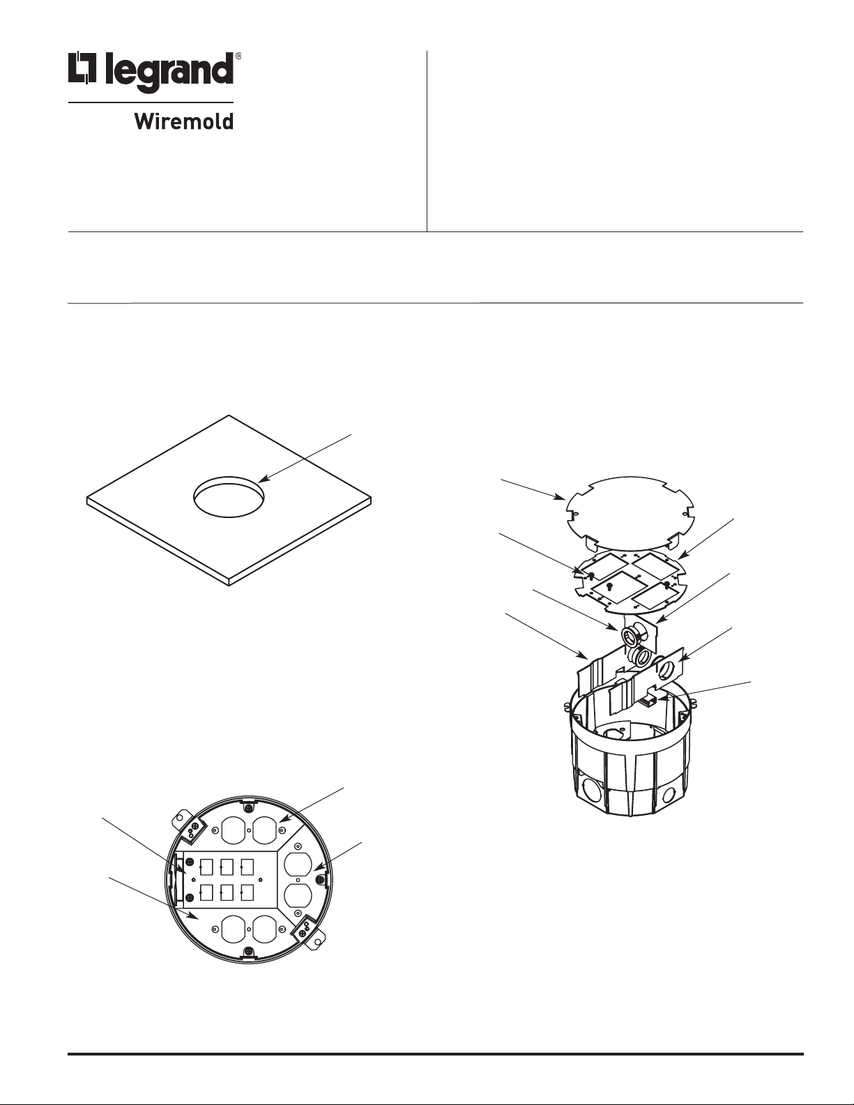
1. Prior to installation, an 8-3/8 ± 1/8 in. [213 ± 3 mm]
diameter hole must be cut or preformed into the raised
floor panel or wood floor. If knockouts on sides of box
are to be used, proceed to steps 4 and 5. Pull cable and
conduit through opening prior to termination.
3/8" ± 1/8"
8
213 ± 3mm]
[
NOTE: Floor thickness range (including floor
covering 3/8" – 2" [9.5mm – 51mm].
3. Attach flexible conduit and fittings to the steel box body.
Terminate wiring devices in compliance with the NEC
and local codes. Cover each compartment with the
Device Plate that matches both the Location and Type
of Device used.
2. If necessary, use bushing(s) and wire tunnel to facilitate
wire and cable routing. Remove the temporary cover and
the (5) #8 hex screws securing the device mounting plate
and lift it out of the box, exposing the internal barriers.
Remove necessary knockouts and twistouts between
compartments to allow desired wiring layout. Replace the
internal barriers and reinstall the device mounting plate
back in its original orientation.
emporary
T
Cover
Device Mounting
#8 Hex
Screw
Right
Barrier
Bushing
Plate
Center Barrier
(with KO removed)
Left
Barrier
Wire
Tunnel
Device
Location #4
Device
Location #2
Device
Location #1
Device
Location #3
Page 2
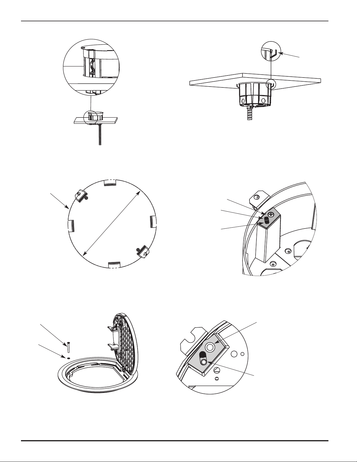
4. Flip locking anchor up and lower box into opening.
5. Tighten mounting screw until steel anchor is adjusted
securely below floor.
Steel
Anchor
6. Install the floor covering prior to attaching the cover.
For carpet installations, the temporary cover plate can
be used as a template.
Cut Carpet along
Temporary Cover Edge
9"
[229mm]
8. CRFBBTC and CRFBCTC COVERS: Open the lid and
insert Cover Attachment Screws through Sealing
Washers and attach Cover Flange to CRFB4 Box.
Attachment
Screw
7. Attach cover to box. Remove the appropriate shelf pad
tab, exposing the threaded attachment hole. Secure
cover to box with screws provided.
Cover Mounting
Shelf Pad
Remove this Tab
Section to attach
8CT Cover
Remove this Tab
Section to attach
CRFB Cover
Mounting Hole
Sealing
Washer
CAUTION: CRFB4 Floor Box has two sets of Cover
Attachment Holes. Use the attachment holes
furthest away from the mounting screw.
Remove this Tab
Section to mount
CRFB Covers
Page 3

9. 8CT and 8CTC COVERS: Open the lid and insert Cover
ttachment Screws through Sealing Washers and attach
A
Cover Flange to CRFB4 Box.
Attachment
Screw
ealing
S
asher
W
ounting Hole
M
R
S
CT & 8CTC Covers
8
emove this Tab
ection to mount
CAUTION: CRFB4 Floor Box has two sets of Cover
Attachment Holes. Use the attachment
holes closest to the mounting screw.
10. FOR 8CT FLUSH STYLE COVERS INSTALLED IN WOOD FLOORS: Create a pocket 9-3/8" diameter
[283mm] x 7/32" [5.6mm] deep, concentric with mounting hole from step 1. Place gasket (supplied with
cover) in counterbore and attach cover. Apply sealant between edge of hole and flange.
pply Sealant
A
or Grout
9 3/8" [238mm]
Counterbore
7/32" [5.6mm]
Deep
Gasket
11. For factory wired CRFB4 access floor boxes, use
Installation Instructions supplied with Walkerflex
®
Modular Wiring Systems.
CAUTION: Do not make or break connections
while circuits are energized.
Page 4

CRFB Cutting Template
2 15/16"
[74mm]
25/32"
2
71mm]
[
7 5/32"
Ø
182mm]
[
R 1/4"
[6.3mm]
4 11/16"
119mm]
[
6 13/32"
[163mm]
CAUTION: When printing copies of this
template, please be sure template
is scaled correctly and is the
correct size once it is printed.
Ø 13/16"
[20.7mm]
2 13/16"
[71mm]
15/32"
[11.6mm]
R 3 9/16"
[91mm]
© Copyright 2010 Legrand/Wiremold All Rights Reserved
2 3/16"
[56mm]
2 3/4"
[70mm]
3 5/16"
[84mm]
WIREMOLD
U.S. and International:
60 Woodlawn Street • West Hartford, CT 06110
1-800-621-0049 • FAX 860-232-2062 • Outside U.S.: 860-233-6251
Canada:
570 Applewood Crescent • Vaughan, Ontario L4K 4B4
1-800-723-5175 • FAX 905-738-9721
1 009 621 0910
 Loading...