

Page 1
INSTALLATION INSTRUCTIONS
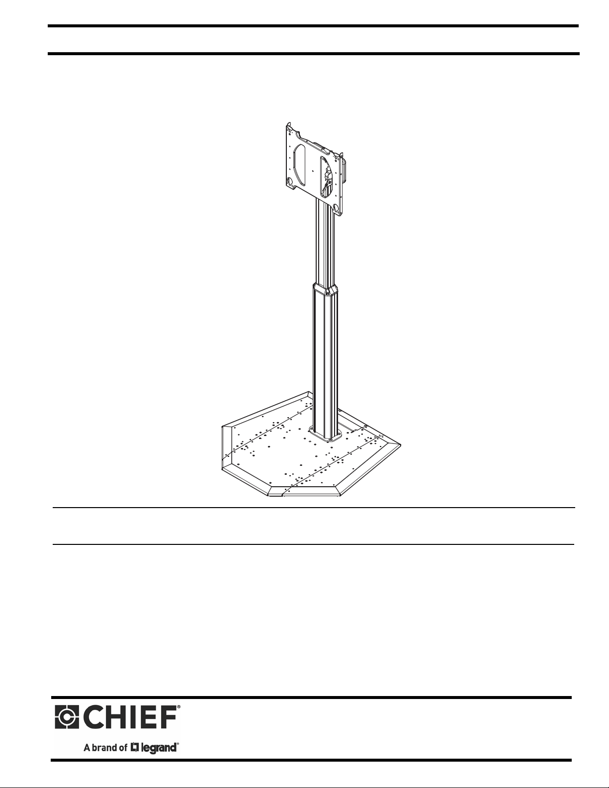
Portable Flat Panel Stand
Spanish Product Description
German Product Description
Portuguese Product Description
Italian Product Description
Dutch Product Description
French Product Description
PRSU
Page 2
PRSU Installation Instructions
DISCLAIMER
Legrand | AV and its affiliated corporations and subsidiaries
(collectively “Legrand | AV”), intend to make this manual
accurate and complete. However, Legrand | AV makes no claim
that the information contained herein covers all details,
conditions or variations, nor does it provide for every possible
contingency in connection with the installation or use of this
product. The information contained in this document is subject
to change without notice or obligation of any kind. Legrand | AV
makes no representation of warranty, expressed or implied,
regarding the information contained herein. Legrand | AV
assumes no responsibility for accuracy, completeness or
sufficiency of the information contained in this document.
Chief® is a registered trademark of Legrand AV Inc.
WARNING: Never operate this mounting system if it is
damaged. Return the mounting system to a service center for
examination and repair.
WARNING: Do not use this mounting system outdoors.
WARNING: RISK OF SERIOUS INJURY OR DEATH!
Placing a remote control or toy on the stand may encourage a
child to climb onto the stand causing the stand to tip over
onto the child. DO NOT place remote controls or toys on the
stand!
DEFINITIONS
MOUNTING SYSTEM: A MOUNTING SYSTEM is the
primary Chief product to which an accessory and/or component
is attached.
ACCESSORY: AN ACCESSORY is the secondary Chief
product which is attached to a primary Chief product, and may
have a component attached or setting on it.
COMPONENT: A COMPONENT is an audiovisual item
designed to be attached or resting on an accessory or mounting
system such as a video camera, CPU, screen, display,
projector, etc.
WARNING: A WARNING alerts you to the possibility of
serious injury or death if you do not follow the instructions.
CAUTION: A CAUTION alerts you to the possibility of
damage or destruction of equipment if you do not follow the
corresponding instructions.
IMPORTANT SAFETY INSTRUCTIONS
WARNING: Failure to read, thoroughly understand, and
follow all instructions can result in serious personal injury,
damage to equipment, or voiding of factory warranty! It is the
installer’s responsibility to make sure all mounting systems
are properly assembled and installed using the instructions
provided.
WARNING: RISK OF SERIOUS INJURY OR DEATH!
Relocating audio and/or video equipment to the stand may
result in the stand collapsing or overturning onto a child. DO
NOT relocate audio and/or video equipment to the stand!
CAUTION: Do not use the column handles for carrying,
transporting, lifting or moving the PRSU. The handles should
only be used for adjusting the column height (with display and
cables removed).
CAUTION: Engage latch lock BEFORE loading stand.
Unload stand BEFORE disengaging the latch.
CAUTION: PINCH POINT! Keep hands clear when folding
the base.
NOTE: The PRSU stand has no user serviceable parts.
NOTE: The PRSU should be regularly inspected for damage.
NOTE: The PRSU stand can support screen sizes up to a
maximum of 80" diagonal.
--SAVE THESE INSTRUCTIONS--
WARNING: For use with televisions weighing 200 lbs (90.7
kg) or less. Use with heavier televisions may result in
instability causing tip over resulting in death or serious injury.
WARNING: Use this mounting system only for its intended
use as described in these instructions. Do not use
attachments not recommended by the manufacturer.
2
Page 3
Installation Instructions PRSU
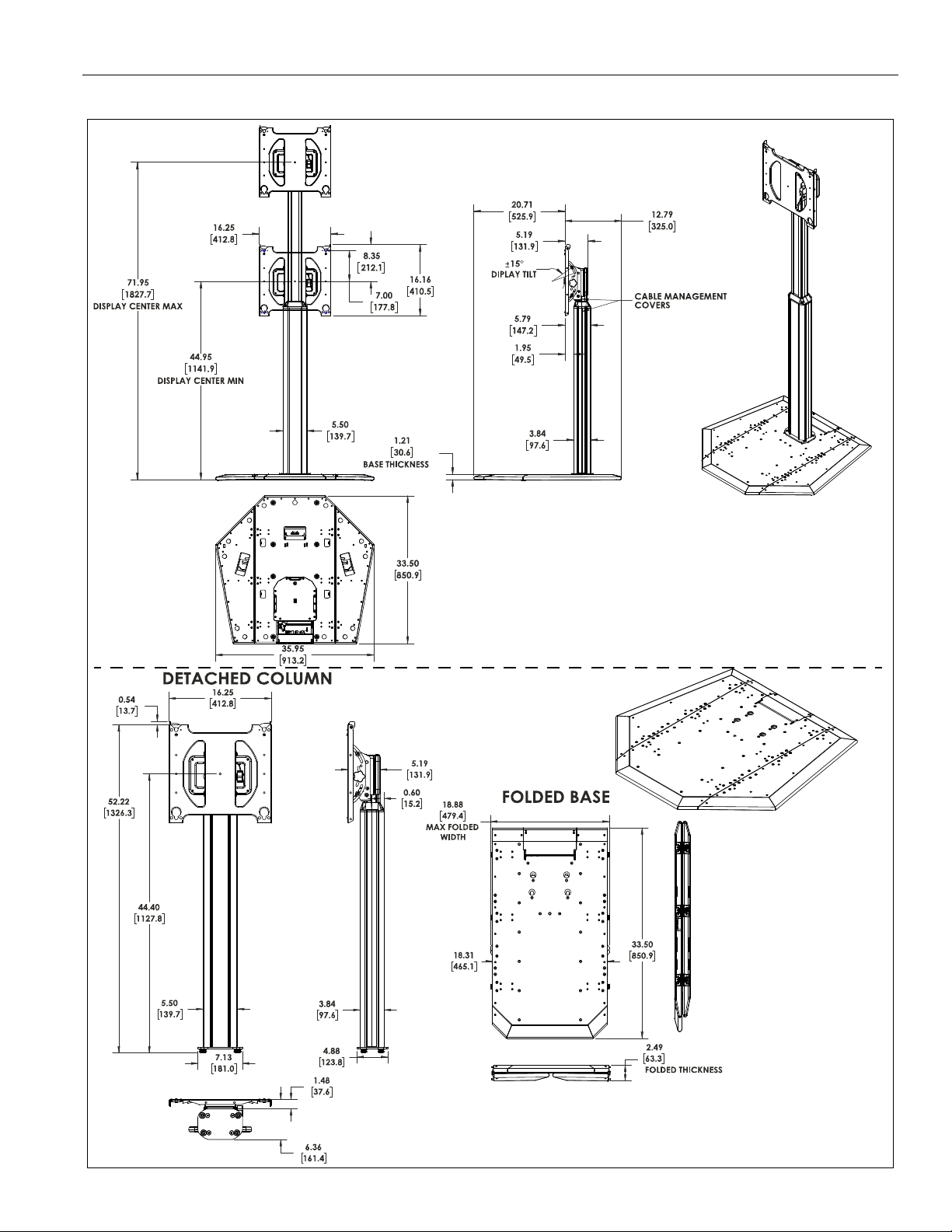
WEIGHT CAPACITY: 200 LBS (90.7 KG)
DIMENSIONS: INCHES
[MILLIMETERS]
DIMENSIONS
3
Page 4
PRSU Installation Instructions
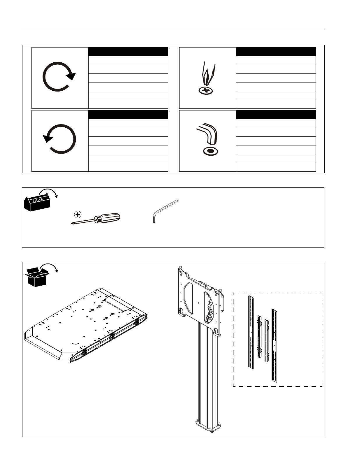
Tighten Fastener
Apretar elemento de fijación
Befestigungsteil festziehen
Apertar fixador
Serrare il fissaggio
Bevestiging vastdraaien
Serrez les fixations
Loosen Fastener
Aflojar elemento de fijación
Befestigungsteil lösen
Desapertar fixador
Allentare il fissaggio
Bevestiging losdraaien
Desserrez les fixations
Phillips Screwdriver
Destornillador Phillips
Kreuzschlitzschraubendreher
Chave de fendas Phillips
Cacciavite a stella
Kruiskopschroevendraaier
Tournevis à pointe cruciforme
Hex-Head Wrench
Llave de cabeza hexagonal
Sechskantschlüssel
Chave de cabeça sextavada
Chiave esagonale
Zeskantsleutel
Clé à tête hexagonale
#2
1/8"
(included with PSBU
Interface Bracket)
A (1)
[Base]
B (1)
[Column assembly]
[Includes vertical
C (1)
[PSBU Interface Bracket]
and horizontal
brackets,
installation
instructions and
hardware]
LEGEND
TOOLS REQUIRED FOR INSTALLATION
PARTS
4
Page 5

Installation Instructions PRSU
2
2
H
i
n
g
e
a
r
e
a
H
i
n
g
e
a
r
e
a
View of base bottom - folded
View of base bottom - open and locked in place
3
3
4
5
(A)
Column latching
handle
Hold column
assembly on
faceplate or
Do NOT grasp
handles to
carry column
assembly
column
ASSEMBLY
1. Determine location for PRSU stand, and place base (A) on
floor with folded ends on top. (See Figure 2)
2. Open both sides of the base (A), being careful to keep
fingers from hinge areas. (See Figure 1)
Figure 3
CAUTION: Do not use the column handles for carrying,
transporting, lifting or moving the PRSU. The handles should
only be used for adjusting the column height (with display and
cables removed).
Figure 1
3. When the base sides are extended to the open position they
will lock in place. (See Figure 2)
Figure 2
4. Place base on floor (top side up), and lift cover at center
back of base (A). (See Figure 3)
5. Ensure that column latching handle is at far left of opening.
(See Figure 3)
Figure 4
5
Page 6
PRSU Installation Instructions
(B)
(A)
6
8
7
9
Locking handle
[UNLOCKED]
Locking handle [LOCKED]
[column not shown]
2
3
1
Inner
handle
6. With faceplate facing front of base, line up column with
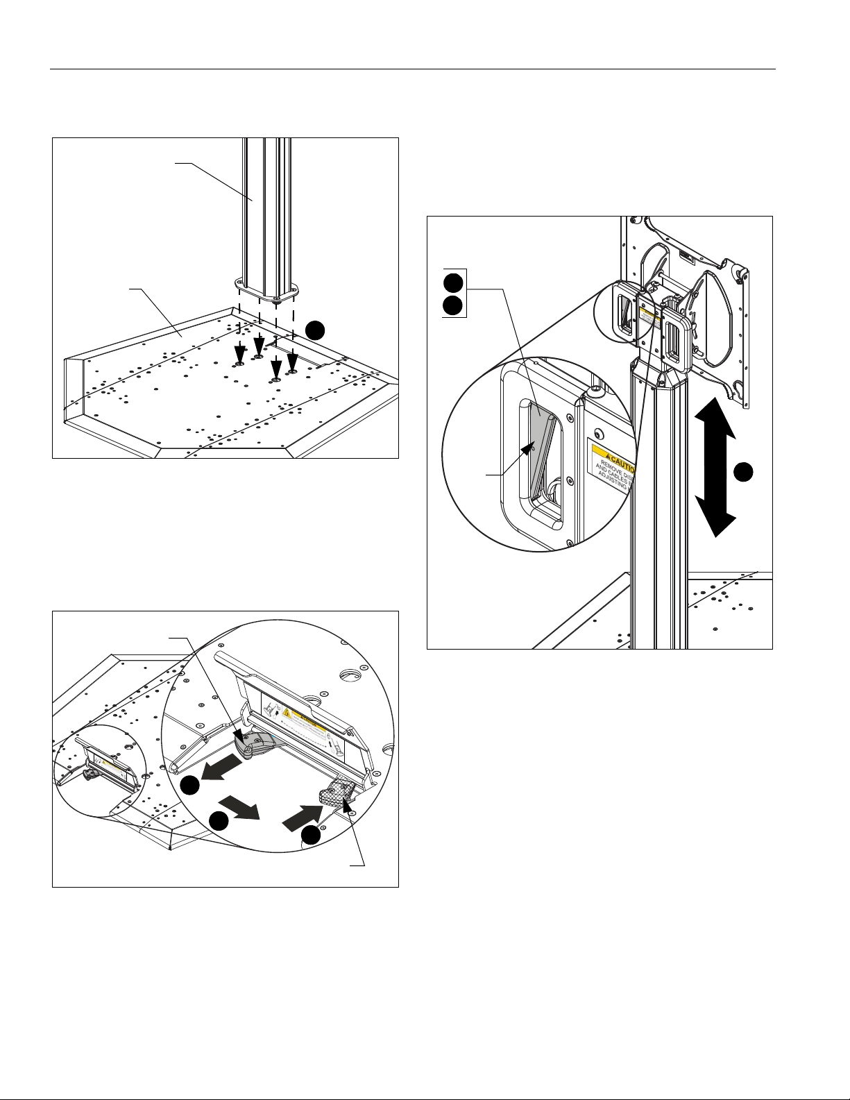
mounting holes in base and lower into place. (See Figure 5)
Figure 5
Installing Interface Bracket
1. Prepare to adjust height of column by holding both handles,
pulling the inner handle and lifting. (See Figure 7)
2. Adjust height of column up or down as required.
3. Release the inner handle to move column to the closest
height setting and to lock column height in place.
7. Pull out column latching handle. (See Figure 6)
8. Move handle to right until it retracts at the far right side of
opening. (See Figure 6)
9. Ensure that handle retracts into base (A) to lock column (B)
into place. (See Figure 6)
Figure 6
Figure 7
4. Assemble and install the PSBU interface bracket to the
display, following installation instructions included with the
PSBU interface bracket.
6
Page 7
Installation Instructions PRSU
OPEN
CLOSED
1
2
4
2
3
Padlock may be
used through
latch hole after
flag has been
closed.
Attaching Display to Stand
WARNING: EXCEEDING MAXIMUM WEIGHT CAPACITY
MAY LEAD TO SERIOUS PERSONAL INJURY OR
DAMAGE TO EQUIPMENT! It is the installer’s responsibility
to ensure the total amount of weight placed on the stand does
not exceed 200 lbs (90.72 kg).
CAUTION: Before attaching display to the stand ensure the
stand is on level surface.
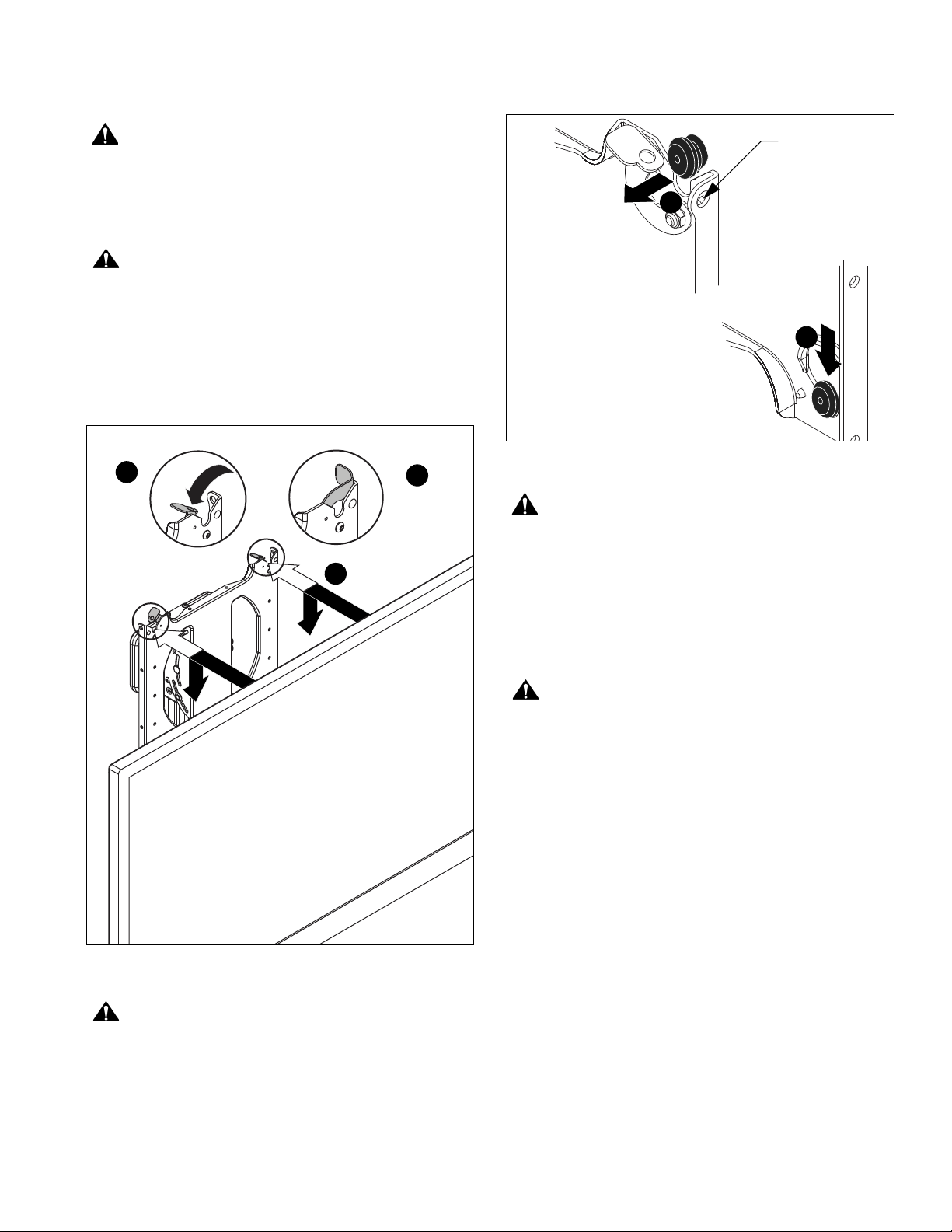
1. Open both flags on top mounting holes in faceplate. (See
Figure 8)
2. While supporting both sides of display, align four mounting
buttons on PSBU with four mounting holes in faceplate.
(See Figure 8)
Figure 9
WARNING: IMPROPER INSTALLATION CAN LEAD TO
STAND OR DISPLAY FALLING CAUSING SERIOUS
PERSONAL INJURY OR DAMAGE TO EQUIPMENT!
Ensure mounting buttons are completely engaged in
mounting holes.
NOTE: Holes are provided in the faceplate for use with a
padlock or similar locking device, if desired. (See
Figure 9)
CAUTION: ALWAYS remove the display BEFORE
adjusting the height of the stand.
Figure 8
CAUTION: THE DISPLAY MAY WEIGH IN EXCESS OF 40
LBS! Always use two people and proper lifting techniques
when installing, removing or positioning display on stand.
3. Lower display into place ensuring recessed area of
mounting buttons are properly seated in lower area of
mounting holes. (See Figure 9)
4. Close flags to secure interface to mount. (See Figure 8)
7
Page 8
PRSU Installation Instructions
1
3
4
Place optional bolt
(not provided) here
to lock in an upright
position.
Cable
management
flaps - located
on both sides of
column
1
1
2
Adjusting Stand
Tilting Display
The display can be tilted up to 15o either backward or forward
from a straight upright position.
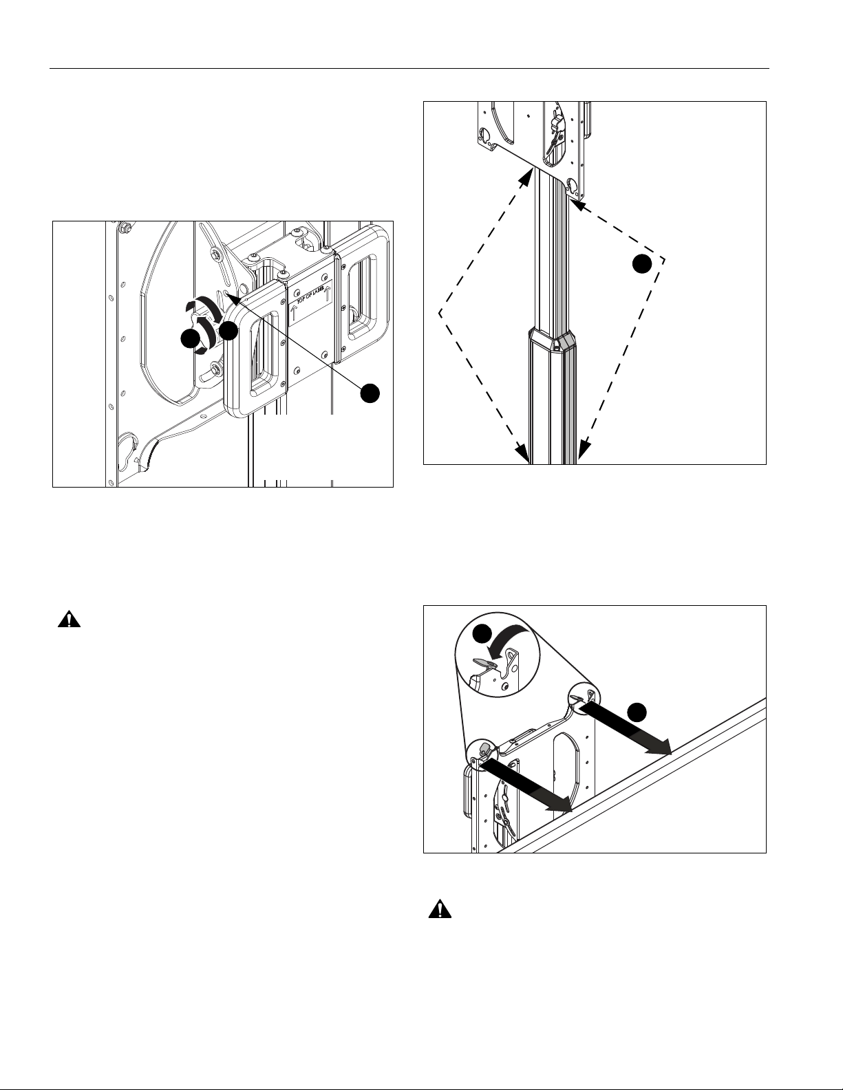
1. Turn knob counterclockwise on side of head assembly to
loosen the tilt. (See Figure 10)
Figure 10
2. Tilt display as desired, to a maximum of 15o either forward
or backward.
3. Turn knob clockwise to tighten display on head assembly.
(See Figure 10)
CAUTION: Tighten knob on side of head assembly to
prevent damage to the stand.
4. If leaving the display in a straight upright position, it is
recommended that a bolt (not provided) be placed through
the head assembly (See Figure 10) to lock the display into
the upright position.
Cable Management
1. Cables may be run down either side of the stand within the
cable management flaps. (See Figure 10)
NOTE: To prevent damage, remove cables from cable
management flaps before moving the display and also
before lowering the stand.
Figure 11
Disassembling Stand
Removing Display from Stand
1. Rotate flags to OPEN position on two upper mounting
holes. (See Figure 12)
Figure 12
WARNING: EACH DISPLAY MAY WEIGH IN EXCESS OF
40 LBS! Always use two people and proper lifting techniques
when installing, removing or positioning display on stand.
2. Carefully lift display and remove from stand.
8
Page 9
Installation Instructions PRSU
3
4
1
2
(A)
Column latching
handle
5
4
3
Locking handle
[UNLOCKED]
Locking handle [LOCKED]
[column not shown]
1
Flat lock
release tab
View of base bottom - folded
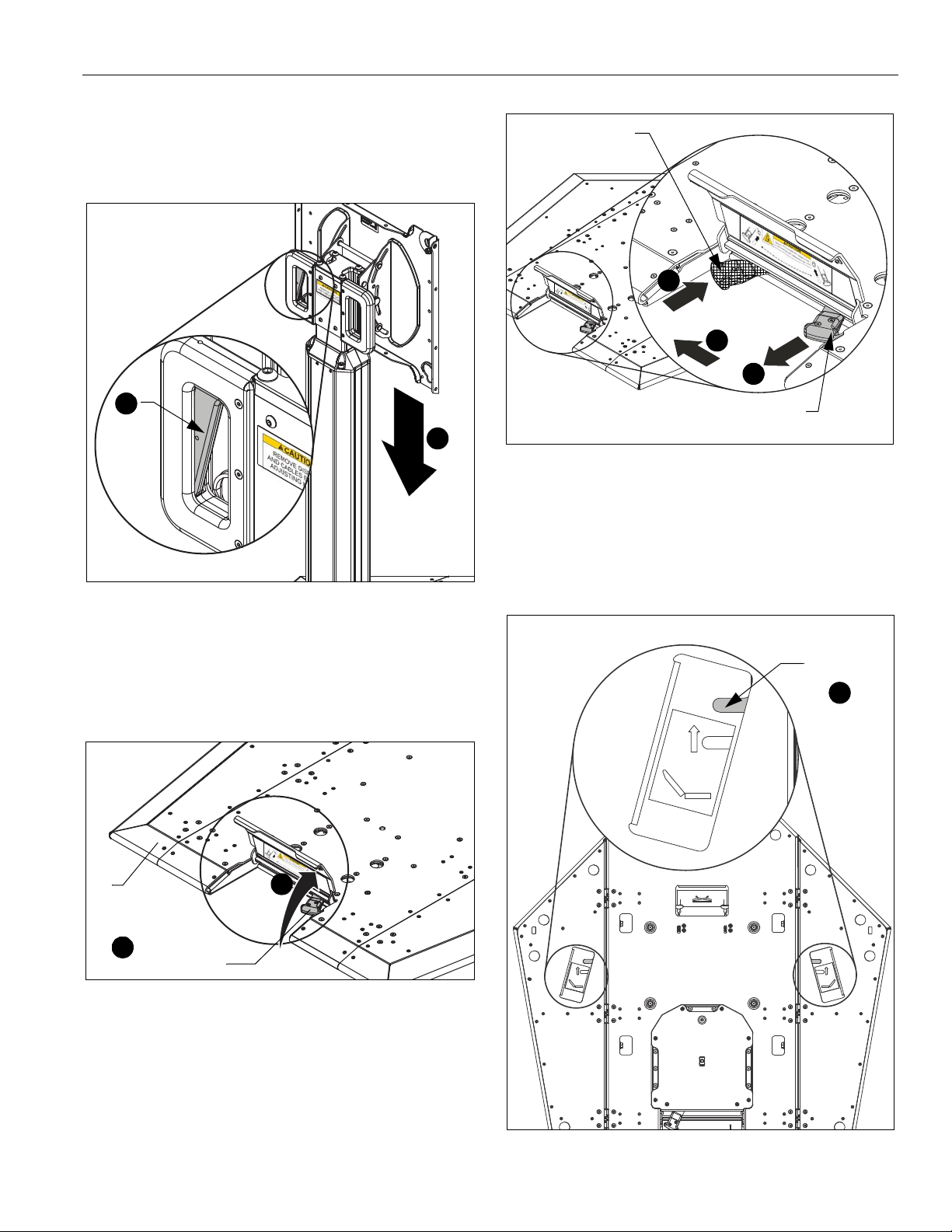
3. Prepare to lower faceplate by lifting it slightly and pulling the
inner handle on back of faceplate. (See Figure 13)
4. Lower faceplate as far as column allows.
5. Release the inner handle to lock column in place.
Figure 15
6. Pull up on column handles and lift column from base.
Removing Column from Base
1. Lift cover at center back of base (A). (See Figure 14)
2. Ensure that column latching handle is at far right of opening.
(See Figure 14)
Folding Base
1. Turn base over and unlock sides of base by lifting the flat
lock release tab on each side, and moving the sides to a
folded position. (See Figure 16)
Figure 13
3. Pull out column latching handle. (See Figure 15)
4. Move handle to left until it retracts at the far left side of
opening. (See Figure 15)
5. Ensure that handle retracts into base (A) to unlock column
(B) from base. (See Figure 15)
Figure 14
Figure 16
9
Page 10
PRSU Installation Instructions
2
2
View of base bottom - folded
Fold
lock tab
3
Carry base at this slot
To
unlock
To
unlock
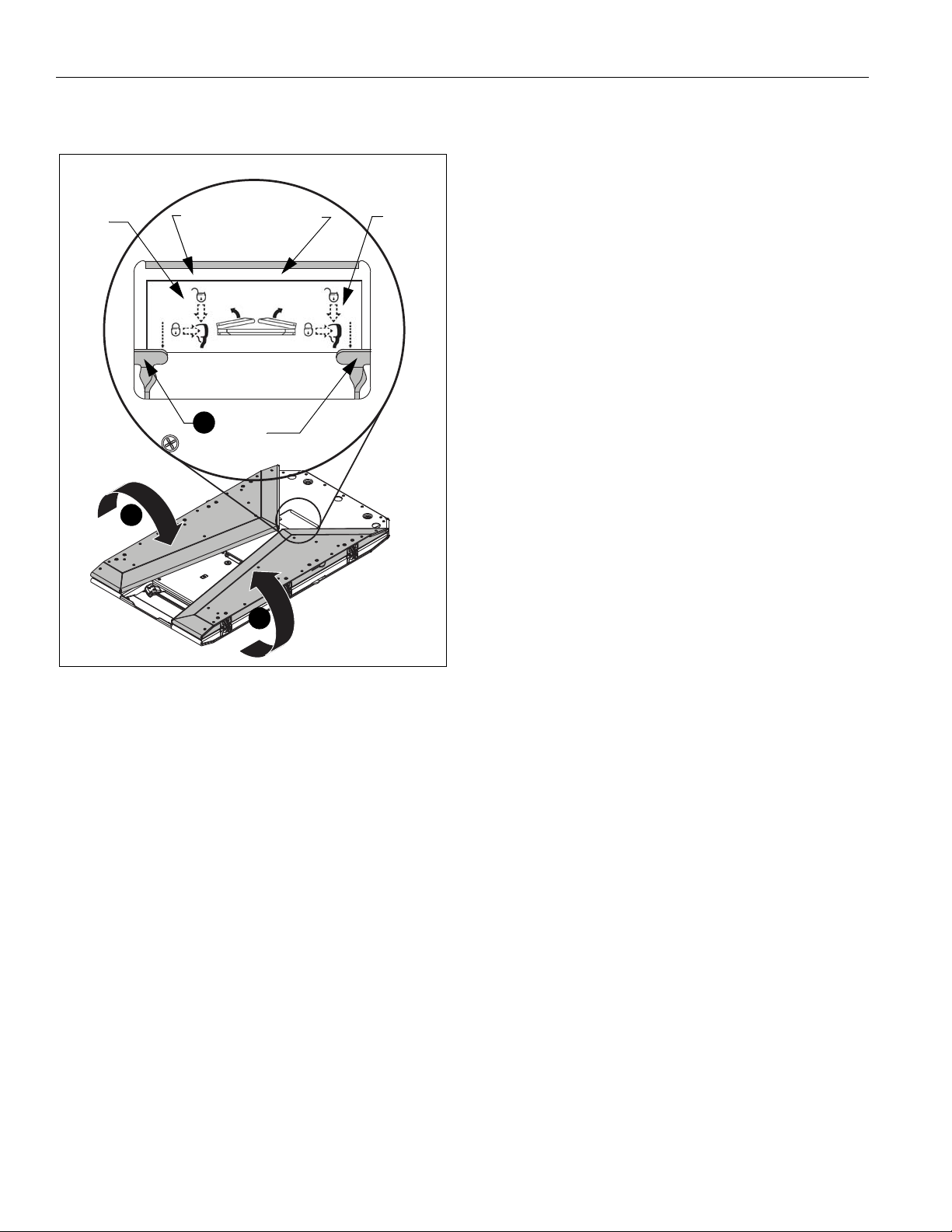
2. Fold up sides of the base, being careful to keep fingers from
between sides and center base. (See Figure 17)
3. Push straight in on each of the fold lock tabs to lock each
side of the base in the folded position. (See Figure 17)
NOTE: Carry the base by using the slot on the bottom of the
base. (See Figure 17)
NOTE: TO UNLOCK FROM FOLDED POSITION - Push
straight down (or toward back of base) on both fold lock
tabs to unlock the sides of the base and allow them to
be opened to the flat base position. (See Figure 17)
Figure 17
10
Page 11

Installation Instructions PRSU
11
Page 12

PRSU Installation Instructions
8800-002993 Rev01
2019 Legrand | AV
www.legrandav.com
04/19
USA/International A 6436 City West Parkway, Eden Prairie, MN 55344
P 800.582.6480 / 952.225.6000
F 877.894.6918 / 952.894.6918
Europe A Franklinstraat 14, 6003 DK Weert, Netherlands
P +31 (0) 495 580 852
F +31 (0) 495 580 845
Asia Pacific A Office No. 918 on 9/F, Shatin Galleria
18-24 Shan Mei Street
Fotan, Shatin, Hong Kong
P 852 2145 4099
F 852 2145 4477
 Loading...