

Page 1
Part. U3330B - 12/09-01 PC
Colour Touch Screen
User manual
5739 60
Page 2

Page 3

Index
Introduction 1. 5
The Touch Screen ■ 6
General description ✔ 6
The Home page ✔ 6
The functions page ✔ 7
Navigation arrows ✔ 7
The Default page ✔ 8
Use 2. 9
The applications 1 ■ 0
Scenarios 1 ✔ 1
Lighting 1 ✔ 3
Automation 1 ✔ 5
Gate (lighting / video door-entry system) 1 ✔ 6
Load control 1 ✔ 8
Temperature control 1 ✔ 9
Burglar alarm 2 ✔ 7
Sound System 2 ✔ 9
Multi-channel sound system 3 ✔ 2
Multimedia contents 3 ✔ 4
Improved scenarios and schedulers 3 ✔ 8
Video door-entry system 4 ✔ 2
Systems supervision 4 ✔ 3
Energy management 4 ✔ 6
Customisation 53. 1
Setup 5 ■ 2
Alarm clock 5 ✔ 2
Beep 5 ✔ 4
Clock 5 ✔ 4
Display 5 ✔ 5
Calibration 5 ✔ 7
Password 5 ✔ 9
Version 6 ✔ 0
3
Page 4

Page 5

Introduction
The Touch Scree ■ n
General descriptio ✔ n
The Home pag ✔ e
The functions pag ✔ e
Navigation arrow ✔ s
The Default pag ✔ e
1
Page 6
1 - Introduction
The Touch Screen ■
General description ✔
The colour Touch Screen is the ro om control that can enable you to
achieve a centralise d management for all My Home Legrand functio ns
in a simple an d intuitive way.
When you touch the icons of the wide display lightly with your finger, it
is pos si bl e to con tr ol a nu mb er o f M y Ho me Leg ra nd sol ut io ns, su ch a s:
controlling actuators for lights and shutters, selecting preset scenarios,
adjustin g the temper ature of the temperature control zone s, dividing
and enabling/disabling the burglar alarm, managing the sound system,
forcin g the priority of household appliances manag ed by the load
control and many others.
The Touch Screen is always switched on and enabled, the back lighting
of the displ ay turns on as soon as you tou ch it.
All the navig ation pages of the Touch Scree n wil l be created and
customis ed for the My Home Legrand solutions in your system by the
installer, according to yo ur needs.
The naviga tion pages in this manual are given f or guidance only.
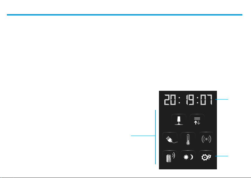
The Home page ✔
There are ico ns in the Home page which repr esent the applicatio ns
that you can manage as well as the setup i con (always present). When
pr og ram mi ng , it is pos si bl e to ent er mo re i nf or mat io n su ch as t he dat e,
time and temperature (the possibility to enter information depends on
the space va cated by the icons).
For more inf ormation, please c all your installer.
Applications
6
Time
Setup
Page 7

1 - Introduction
The functions page ✔
You can access the functions page by selecting the required application
from the Home page.
All you need to do is touch the icon of a comman d to switch on a light,
pull up your rolling shutter or ac tivate a scenario.
NIGHT
Shutter
DAY
Gate
Watering system Scenario module
Automation page example Scenario page example
Navigation arrows ✔
The arrows at the b ottom part of t he displ ay hav e the followi ngs
functions:
Scrolls th e contents of the page
upwards
Scrolls th e contents of the page
downwards
Goes to the p revious page
In some pages there is a fourth button that allows you to execute
special f unctions.
7
Page 8
1 - Introduction
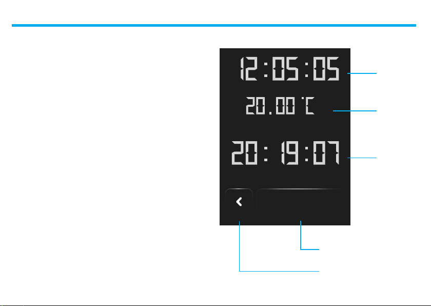
The Default page ✔
The ColorTouchConfigIP configuration software enables you to specify
a Default page which will be shown on the display after a period of
inactivity of th e Touch Screen.
The installer can ch oose the Home page or a p age included in the ap plicatio ns as the Def ault page; it will also be p ossible to create a ne w
page containing information on the Time, Date and temp erature. In
alternative to Time and Date, the Temperature can b e entered up to
three times, thereby enablin g you to monitor three differe nt rooms.
In additio n to the navigation arrow (tha t allows to ret urn to the Home
Page), there is an icon at the bot tom of the page which allows you to
execute a command . For mor e informatio n on how to confi gure the
command, p lease call your inst aller.
If t his page has not been ena bled during th e configur ation process,
the Home Page will be displayed.
Date
Temperature
KITCHEN
Time
COMMAND
Control button
Navigation arrow
8
Page 9

Use
The application ■ s
Scenario ✔ s
Lightin ✔ g
Automatio ✔ n
Gate (lighting / video door-entry system ✔ )
Load contro ✔ l
Temperature contro ✔ l
Burglar alar ✔ m
Sound Syste ✔ m
Multi-channel sound syste ✔ m
Multimedia content ✔ s
Improved scenarios and scheduler ✔ s
Video door-entry syste ✔ m
Systems supervisio ✔ n
Energy managemen ✔ t
2
Page 10
2 - Use
The applications ■
The Touch Scre en enables you to manag e the following applications
of the system:
Th e S et up i co n, a lw ay s pr es en t in th e Ho me pa ge , ca n l et y ou ac ces s t he
Touch Screen setup page (A larm clock, Beep, Clock, e tc.).
Scenarios
Lighting
Automation
Load control
4 zone
temperature control
99 zone
temperature control
Energy management
Burglar alarm
Sound
Syste m
Multi-channel
sound system
Improved
scenario s and
schedulers
Video
door-entry
system
Syste m
supervision
DISPLAY
VERSION
NETWORK
For more inf ormation see chapter “Customis ation”.
10
Page 11
2 - Use
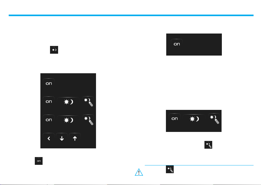
Scenarios ✔
Lets you ac tivate scen arios that have been previously stored in one
or more “scenario units” and “scenario modules” of your My H ome
Legrand s ystem.
Touch the scenar io icon .
The display wil l show the page where you can find the scenarios you
can acti vate.
NIGHT
Scenario 1
Scenario 2
Touch the icon to activate the s cenario.
Scenario of the Scenario unit
NIGHT
This command lets you a ctivate a scenario of the Scena rio Unit.
You can f reely decide to modify the scenario setting on the Unit; the
Touch Screen will then exe cute the scenario you have set up.
Scenario of the Scenario Module
Scenario 1
This command lets you a ctivate a scenario of the Scena rio Module.
Further more, whe n you touch the icon , new icons will appear
which will allow you to cancel or programme a new scenario according
to the func tioning mode of the Scenario M odule.
If the icon is n ot dis played , th e s cenar ios mo dule is
blocked.
11
Page 12
2 - Use
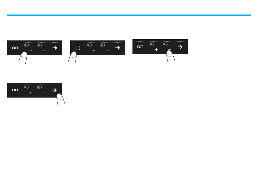
Creating a new scenario
Touch the icon to st art
a new scenar io
programming proce dure.
Touch the icon to return
to the menu of t he scenarios
programmed by you.
Touch the icon to end
programming.
Removing a scenario
Touch the icon to remove a scenar io
programmed by you
12
Page 13
2 - Use
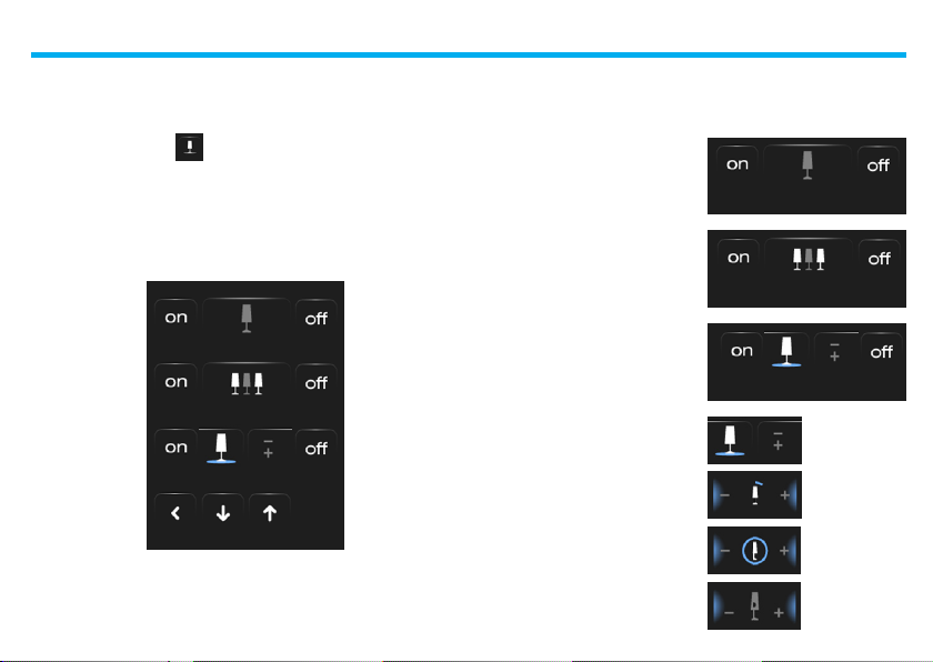
Lighting ✔
Lets you sw itch on, switch off, adjust a single light or group of lights.
Touch the lightin g icon .
The disp lay will show the page where you can find the lights you can
control.
Kitchen light
Garden lights
Staircase light
Depending on the programming condition, the display can have seven
diffe rent types of contr ols:
Single light
This control let s you switch a
single light on and of f.
Kitchen light
Group of lights
Thi s co ntrol let s y ou s witch
on/ off a group of lights simultaneously.
Garden lights
Dimmer
Th is con tr ol l et s y ou s wi tc h on ,
switch off and adjust a light
with a dimme r.
Use the – an d + icons for t he
adj ustm ent; the bri ghtn ess
of the light is shown graphical ly.
The illumi nation intensity w ill
be shown with ON/OFF marks
(10 le vel s) or mar ks wi th a
lower illumination intensity
(100 levels), depending on the
dimmer installed (10 or 100
levels).
If the light does not work or if
it is not connected, a broken
light bulb will appear.
13
Staircase light
Less light
Dimmer 100 or
10 leve ls, 90%
ON.
Fault
Page 14

2 - Use
Dimmer Assembly
Th is con tr ol l et s y ou s wi tc h on ,
switch off and adjust several
light s si multane ously with a
dimmer.
Use the – and + icons f or the adjustment; th e brightness of the light is
not shown gr aphically.
The dimmers of the assembly can be adjusted at differe nt illumination
intensity levels, hence they can be adjusted by increasing or decreasing
the level of a ll dimmers, star ting from their current adjus tment.
Room lights
Timed light with preset durations
Thi s co ntrol let s y ou s witch
on a light thu s sett ing
the activation time with the
icon .
1’
Ti ming w ith pr eset dur atio ns
not enabl ed
1’
Ti ming w ith pr eset dur atio ns
enabled
The durations that can be set may be:
fixed: 7 dif ferent durations that cannot b e changed
config urable: 20 durations configur able through sof tware
Fixed timed light
Thi s co ntrol let s y ou s witch
on a light for only o ne set
duration using the confi guration sof tware.
The icon shows the remai ning ac tivat ion tim e (in
percentage).
The i con show s the timin g
activation stat us.
Staircase light
This control lets you activate
the Staircase lights function of
the video door-entry system.
14
12:10
Fixed timin g disabled
12:10
Fixed timin g enabled
(about half the ti me re maining
to switch of f)
Page 15
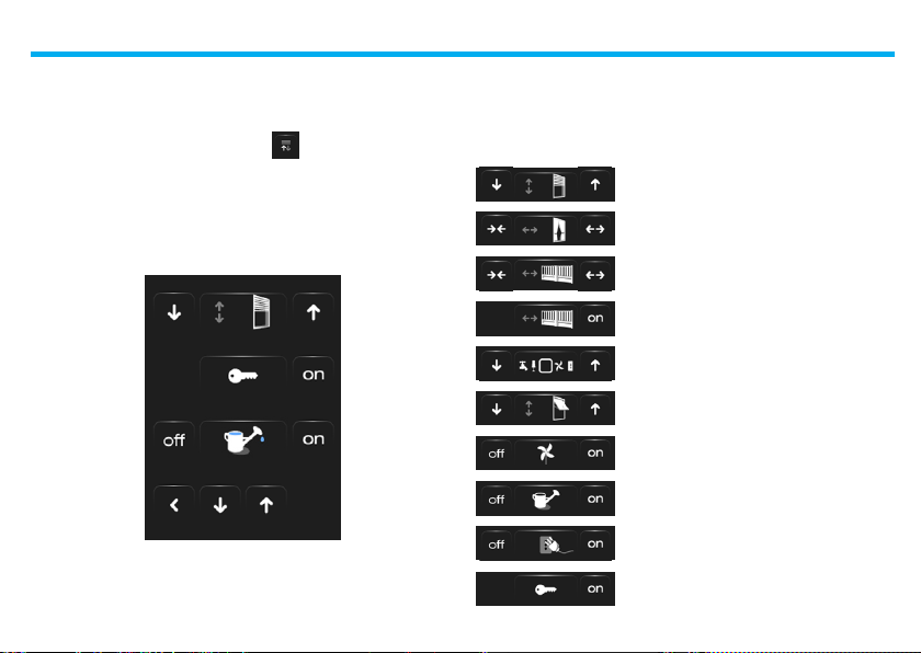
Automation ✔
Lets you control shut ters, gates, door l ocks, etc.
Touch the automation contro l unit icon .
The display will show the page wh ere you can find the automation
control uni ts that you can control.
Shutter
2 - Use
In o rder for you to have an immediate identif ication, di fferent icons
have been created accord ing to the actual use of the automation
control uni t.
Shutter
Curtain
Gate (automation)
Gate (lighting/video door-entry system)
Automation assembly
Gate
Watering system
Up-and-over
Fan
Watering system
Controlled plug
Door lock
15
Page 16
2 - Use
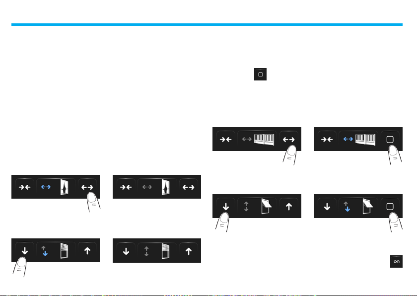
Curtain - Shutter - Gate – Up-and-over
These controls allow you to open and close the curt ains, shutters, e tc.
with a simpl e touch of your finge r.
The operation may occur in two different ways, depending on the
programming proce dure carried out by t he installer:
Safe mode
Th e o pe nin g o r cl os ing mo vem en t w ill oc cur as l on g a s th e co rr es po nd ing icon is tou ched; the icon change s, thus indicating the movement .
When the icon is releas ed, there will be an automatic stop.
Safe mode examples
The curtain opens when
the icon is kep t pressed
The shut ter goes down when
the icon is kep t pressed
When you lift your f inger,
the curt ain stops
Stop
When you lift your f inger,
the shutter stops
Stop
Normal Mode
The opening or closing movement will start by touching the correspondin g icon; duri ng the move ment the icon changes showing the
Stop icon and th e indication of the movement in progress.
Touch the icon to stop the movement .
Normal mode examples
The gate op ens when you
touch the ico n
The gate clo ses when you
touch the ico n
Press the ico n Stop to stop it
Stop
Press the ico n Stop to stop it
Stop
Gate (lighting / video door-entry system) ✔
The opening or closing movement will start by touching the
icon. The movement automatically stops when the gate reaches its
stop limit .
16
Page 17
2 - Use
Automation assembly
This control can be used to activate several au tomations at th e same
time. For examp le, with a single touch it would be possibl e to lower or
rise all the r olling shutters o f the home.
Movem ent is activate d by touchin g one of the arrow icons. Touch
to stop.
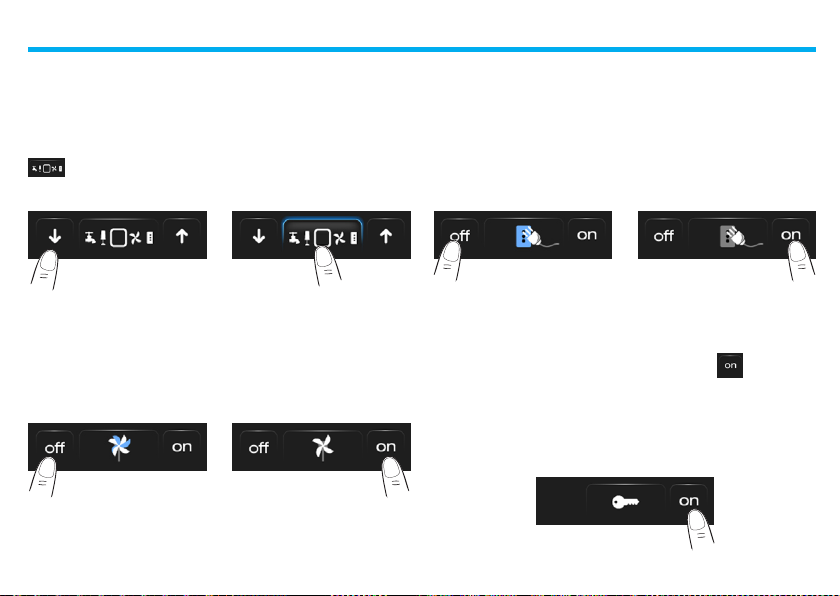
Fan
This contro l lets you switch a fan o n and off.
The icon indicates wh en the fan is in operation.
OFFON
touch to swi tch off touch to swi tch on
Controlled plug
This control, represented by a plug, lets you switch on and off a generic
device (a hous ehold appliance or a ny other device).
Here again, the icon indicates th e status of the device co ntrolled.
OFFON
touch to swi tch off touch to switch on
Door lock
The door l ock is activated wh en you touch the icon .
This control acts as a button: the door lock is activated when you touch
the icon and d eactivated when you releas e it. If it controls a doo r lock
of the video door-entry s ystem, the ac tivation time will be set by the
door lock configuration.
Door lock deacti vated
17
Page 18
2 - Use
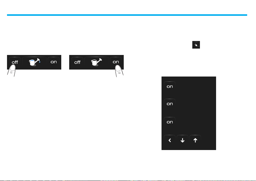
Watering system
This contro l lets you switch the watering system on an d off.
The icon indicates wh en the watering sys tem is in operation.
OFFON
touch to swi tch off
touch to swi tch on
Load control ✔
This control allows you to force the priority set fo r the Energy man agement unit.
Touch the Energy Managem ent icon .
The display will sh ow the page where you can f ind the loads that you
can control.
Microwave
Oven
Washing machine
18
Page 19
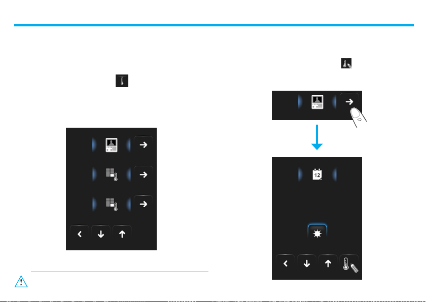
Temperature control ✔
Thi s co ntrol ena bles you kee p the temp eratu re under con trol in
the whole house and to adjust each zon e according to your current
needs.
Touch the tempe rature control icon .
The display shows a page listing systems (Control units), non-controlled
zones (if present) and any external probes (if p resent). If only one
Contro l Unit is pr esent, a scre en will be displayed, with the selecte d
Contro l Unit icon (4 zones/99 zo nes), and the Zone list.
4 ZONE CONTROL UNIT
ZONE 1
ZONE 2
The management of th e temperature control is possible only if
the Remote control function h as been activate d.
2 - Use
Touch th e Control Unit icon to access a p age displaying the Control
Unit st atus. The same page also shows th e icon that gives access
to the list of the possib le modes that can be se t.
4 ZONE CONTROL UNIT
4 ZONE CONTROL UNIT
19
Page 20
2 - Use
Weekly Mode
By selecting one of the 3 summer or winter programs (previously set in
the control unit), the system can operate in automatic mode following
the setup programming proce dure.
Touch the ico n to confirm the program to set.
Winter programsSummer programs
Program 1
Program 2
Program 3
Program 1
Program 2
Program 3
Manual Mode
This can be used to set a constant temp erature in all the zones of the
system.
Touch th e and icons to decrease or increase the temp era-
ture value by 0.5°C. Touch the icon to confirm the temperature
selected.
Manual
23.5°C
20
Page 21

2 - Use
Timed Mode (only for 4 Zone Control Unit)
It can be use d to perform manual mode on all zones for a set period.
Touch the and icons to decrease or increase the temper ature
value by 0. 5°C.
Touch the and icons to set the hours and minutes d uring
which the Control unit o perates in Manual mo de.
Touch the icon to confi rm the temperature and the time s elected.
Manual
23.5°C
Holiday Mode
This is used to select a certain daily profi le for a set time. This pro gram
ru ns u nt il t he se t ti me an d da te , af te r w hic h t he c ur re nt s el ec te d w eek ly
program w ill be restored.
Touch the
Touch the icon to conf irm.
Touch the
Touch the icon to conf irm and select th e program to set.
21
and
icons to set th e date.
and
icons to set h ours and minutes.
Page 22

2 - Use
Working Day Mode
This m ode can be used to ke ep the sys tem in Anti- freeze or Thermal
pr ot ec ti on m od e u nti l t he s et da te a nd ti me. On ce t hi s t ime ha s e xpi re d,
the set wee kly program will be restore d.
Touch the
Touch the icon to conf irm.
Touch the
Touch the icon to conf irm, and select t he program to set.
and
icons to set th e date.
and
icons to set h ours and minutes.
Scenario Mode (only for 99 Zone Control Unit)
If you select one of the 16 summer or the 16 winter scenarios, your sys tem can ope rate in automatic mod e following the scena rio selected.
Touch the ico n to confirm the sele cted scenario.
Winter scenariosSummer scenarios
Scenario 1
Scenario 2
Scenario 3
22
Scenario 1
Scenario 2
Scenario 3
Page 23

2 - Use
OFF Mode
Touch this icon to sw itch all system zone s OFF.
Anti-freeze mode
Touch this icon to set the Anti-freeze temperature for all system
zones.
Summer/Winter Mode
Touch this icon to set the system mode of operation (Summer/
Winter).
Thermal probe
Th e l oc al o f fs et o f t he p ro be is the ad ju stm en t o f th e k no b p lac ed on the
probe situated in ever y zone of your tempe rature control system.
If the probe is set to ❄ (antifrost/thermal protec tion) or OFF position,
no adjus tment will be p ossible from the Touch Screen; to c hange the
settin g, it is necessary to a ct directly on th e knob of the probe.
23
Page 24

2 - Use
Zones (with fan-coil function)
If the probe for the regulation of the fan-coil speed is installed, in addition to displaying the name of the zone and the set and me asured
temperature, this pa ge will also enable se lecting one of the fo llowing
speeds: Minimum, M edium, Maximum an d Automatic.
ZONE 2
ZONE 2
23.5°C
35.0°C
+2
Zone
Measured temperature
Regulati on keys
and set temperature
Probe sta tus
Fan-coil speed
Control uni t mode
Zones (99 zone Control Unit)
If you pr ess the Zone icon , the zone name w ill be displayed, togeth er
with the temper ature measured, the temperature setting, if in manual
mo de , th e a ct iv ati on of t he man ua l/a ut om ati c m od e, t he dis pl ay o f t he
probe st atus (-3 -2 -1 0 +1 +2 +3).
ZONE 1
ZONE 1
23.5°C
35.0°C
+2
24
Page 25

2 - Use
Zones (4 zone Control Unit)
Press the Zone icon to disp lay the zone name, the temperat ure measured and se t, and the probe status (-3 -2 -1 0 +1 +2 +3).
ZONE 1
ZONE 1
23.5°C
35.0°C
+2
External probes
If the system inclu des external radio probe, the temperature detecte d
by them may be displayed through the appropriate zone.
EXTERNAL PROBES
28.5°CGARDEN PROBE
25
Page 26

2 - Use
Non-controlled zones
If the system includes temperature measurement probes only (noncontrolle d zones), the temperat ure detected by them can be displayed
through th e appropriate zone.
NONCONTROLLED ZONES
28.5°CGARAGE
26
Page 27

2 - Use
Burglar alarm ✔
Th is con tr ol a ll ow s yo u to co ntr ol th e st at us of t he bur gl ar ala rm sy ste m
(enabled /disabled) and on sing le zones.
Touch the burgla r alarm icon .
The top par t of the display will show the sys tem status icon (when the
padlock is open it indicates that the system is disabled, when it is closed
it indicates that the syste m is enabled); in the centre, you can scroll the
zones in which it is subdivided and check wh ich are enabled.
system di sabled
system enabled
zone 1 act ivated
Perimeter
zone 2 deac tivated
Basement
Activate/deactivate the zones
When the bu rglar alarm is disabl ed, you can deacti vate (or reactivate)
one or more zones of the system; this will allow you customise the
operati on of the system accordi ng to your needs. You can for example
divide the infr ared sensor zones, leaving the perimeter zones a ctive
(M ain do or a nd wi ndo ws) , s o th at y ou can fr ee ly m ov e in si de t he hou se
without co mpromising on security.
The division is only possible
when the system is disabled,
using the icons for the individual
zones (which are not sh own on
the display when the system is
enabled).
Perimeter
To acti vate this cus tomisat ion
touch the conf irmati on icon: a
pa ge wil l be dis play ed: enter
the user code to confirm system
partition.
To divide and activate the burglar
alarm system at the same time,
simply touch the icon, as shown
in the following page.
27
Basement
Page 28

2 - Use
Enable/disable the burglar alarm
Press the icon to change the s tatus of the s ystem: (to enable).
(to disable).
Enable the b urglar alarm Disable the burglar alarm
Enter your Burglar Alarm U nit user code in the displayed p age and confir m
with .
If the soun d system is enab led, you will he ar the voice messa ge: “enabled” o r “disabled”.
1 2 3 4 5 6 7 8
PASSWORD:
Nu mb er s fr om 1 to 8 at th e bo tt om (av ail ab le onl y i n th e s ys tem en ab led
pa ge ) i nd ic ate th e s ta tu s o f th e d iv is io ns . I n t he ex am pl e, z on es 1 a nd 8 a re
activated, wher eas they are deactivated/excluded fro m 2 to the 7.
1 2 3 4 5 6 7 8
PASSWORD: *****
What type of alarm occurred?
If alarms have occurred while yo u were out, as soon as you get home
you w ill find a screen similar to the one in the e xample with the fol lowing informati on: the centre icon corre sponds to the t ype of alarm
occurred, indicatio n of the time, date, type of alarm and zon e in which
it has occurred.
“Intrusi on” alarm example
intrusion
11:01 17.07 Z 1
The alarm signal rema ins stored until the system is enabled aga in.
Touch the icon in the main page to lo ok at the alarms memory.
Touch the icon to cancel the ala rm.
28
Type d’alarme:
- intrusion;
tampering;
- antipanic;
technical.
Indicati on of the:
- time;
- date;
- zone.
Page 29

2 - Use
Sound System ✔
You can check you r sound system completely.
Touch the sound s ystem icon .
At the bottom par t of the display there is an icon referred to the music
source; in the middle you can scroll the amplifiers yo u want to check.
Radio
Living room
Basement
Music source
You can choose between the Radio tuner and an external source (Aux),
for instance a CD unit controlled with the Stereo Contr ol or connected
by means of a RC A input.
Radio
Change
source
Change channel
(only the sto red ones)
External source
Change
source
Change tra ck
(if included in the source)
29
Radio
AUX
Channel
tuning
Page 30

2 - Use
Tuning in the radio
The Touch Sc reen lets you tune in your sound system radio a nd store
your favour ite channels.
Change
channel
Change
frequency
Store the
selected
channel
Radio
Radio LGR
Audio
source
Frequency
RDS
Function
Channel
search
mode
(Automatic
or manual)
Amplifier
This contro l lets you switch on / of f an amplif ier and adjust its vol ume
using – e +; the volu me level is shown graph ically on the display.
Off
Low volume
High volum e
Amplifier assembly
You can control an amplifier assembly.
The amplifiers o f the assembly can be adjusted at differ ent volume
levels, hence they can be adjusted by increasing or decreasing the level
of all ampli fiers, star ting from their current adjust ment.
30
Page 31

Power amplifier
This control can be used to switch on/off, and manage, the new power
amplifier.
2 - Use
The following page will appe ar:
Radio
Living room
Power Amplifier
ON/OFF icon, to
switch the p ower
amplif ier on or off
Touch the ico n to access the manageme nt menu.
Open the
power amplifier
management
menu
Normal
+1
Treble
+1
Bass
Equalizer
Touch the or icons to selec t the equalizati on curve:
Dance
Treble adjustment
Touch the or icons to adjust the treble level between -10
and +10:
31
+3
Treble
Page 32

2 - Use
Bass adjustment
Touch the or icons to adjust the bass level between -10
and +10:
-1
Bassi
Balance
Touch the or icons to b alance the sou nd between the right
and the lef t channel.
Right balance
2
Loudness (LOUD)
Acti vating LOUD mode enhances low and high frequ encies when
listenin g at low volume.
To activate or deactivate LOUD touch t he or icons.
Multi-channel sound system ✔
You can check you r multi-channel s ound system compl etely.
Touch the multi-channel sound s ystem icon .
In the example, two configured rooms are displayed (Living room and
Bedroom) as well as the ass embly of all the ampli fiers (General).
Tou ch to access the sing le submenus.
Living room
Dining-room
General
32
Page 33

2 - Use
Example:
“General” sub-menu
In this case, the selected source
is the radio.
Example:
submenu of the Room 1
In this case, the selected source
is CD (Aux).
Radio CD
General Dining-room
Room 1
The following functions are include d in the top part of the su bmenu:
change
source
ON
source
opens the
selec ted source
adjustment
menu
Example: submenu of the
“Radio” source
In this pa ge you ca n find all the
radio tuning controls (for more
details, see pag. 30)
Radio
Home ampliers
1:
Radio LGR
33
Radio
Radio
Home ampliers
1:
Radio LGR
When you touch a n ew
page will be disp layed which will
enable yo u to store up to 5 radio
stations.
Page 34

2 - Use
Example: submenu of the
“CD” source
CD
Multimedia contents ✔
In ad dition to the standard so und system sources, the Touch Screen
can also be used to access n etwork multimedia co ntents, such as IP
Radio and M edia Server.
Touch the sound s ystem or multichannel dif fusion system icon .
In the exam ple the display shows th e configured zone (Living ro om).
Select to access the individu al submenus.
Change tra ck
Go to the
previous page
LIVING ROOM
Living room
34
Page 35

Selec t the multimedia sou nd source among the available ones:
2 - Use
Multimedia Sources: IP Radio
This pag e displays the two options for the manage ment of the multi media sou rces using the Ethernet network.
Multimedia
Living room
The following functions are include d in the top part of the su bmenu:
change
source
ON
source
opens the
selec ted source
adjustment
menu
35
Multimedia
Radio LGR 1
Radio LGR 2
Radio LGR 3
IP Radio
Servers
Select on the display to load
a new page for the display of all
radio channels previously saved
using the ColorTouchConfigIP
software.
Page 36

2 - Use
Selec t on the display to load a new page that can be used to control
the IP Radi os through the player.
Name of the r adio
Radio LGR 3
Stop
Play Go to the
Return to th e
previous page
The operation of the touch screen may be slowe r w hen IP radios
with “.mms” ex tension are connec ted.
Return to the
main page
Go to the
previous
radio
following
radio
Multimedia Sources: Media Server
Pc1: Legrand
Pc2: Legrand
Pc3: Legrand
Select Servers from the display
to display a n ew page showing
all PCs connected to the Ethernet
network.
36
IP Radio
Servers
Page 37

2 - Use
Music
When a PC is selected (e.g. Pc3:
Legrand), the display w ill show
a n ew page with all folder s (Im-
ages, Music, Playlist and Video)
of the playe r preset for listening
to music.
ROLLING STONES
LINKIN PARK
BEATLES
U2
Album
Album artists
Various artists
Folder
Select the Music folder and th en
a subfolder (e.g. Various Artists)
to display all a rtists include d in
the multimedia list of the p reset
pla yer.
The Best Of
Selec t an art ist (e.g. U2) to di spl ay
all the CD of the selec ted artist.
Select the Album (e.g. The Best
Of), to d isplay all the tracks in
the CD.
Track: One
Artist: U2
Album: The Best Of
Time: 01:16 of 04:35
37
Beautiful Day.mp3
Numb.mp3
Gone.mp3
One.mp3
Selec t th e desired track (e.g. One.
mp3). The playe r page appears,
showing the details o f the track
being played.
Page 38

2 - Use
Current tra ck details
Track: One
Artist: U2
Album: The Best Of
Stop
Time: 01:16 of 04:35
Play Go to the
Return to th e
previous page
In order to o btain a faster fi le browsing, we suggest to orga nize
the own libr ary in order to have maximum 50 objec ts in each
folder (this value is th e sum of mp3 files and include d folders)
and to brows p er folders.
Re t ur n t o t h e m ai n p a ge
of the soun d system
Go to the
previous track
followin g track
Improved scenarios and schedulers ✔
When you sel ect this applicati on – depending on the configurati on
made by the installer and customised according to the My Home
Legr and s olutions in your system – you can contr ol th e imp roved
scenario s and schedulers (maximum 20).
Touch the improve d scenarios and sche dulers icon .
This example p age displays both f unctions: Schedul ed scenario and
Improved scenario.
38
Start
scenario
Enable
Enable/
Disable
Start
scenario
Scheduled scenario
Improved scenario
Stop
scenario
Disable
Modif y the
scenario
Page 39

2 - Use
Scheduled scenario
Th is sce na ri o al lo ws you to sen d a se rie s o f co mm an ds af ter on e o r mo re
actions have occurre d or at a predetermin ed time.
It is possible to manage up to 20 of the 300 scenarios configure d i n the
Scenario Programmer.
For this scen ario, the four possib le actions are:
– Enable scenario – Disable scenario
These commands allow you to enable/dis able the scenario without
operati ng it. If the scenario is enabled and if the ac tivation condition
occurs, the actio ns of the scenario will b e executed.
– Start - Stop
These are start / stop commands of the scenario, regardle ss of the
programmed condi tion.
Configuration examples
Scheduled scenario
Scheduled scenario
Scheduled scenario
Scheduled scenario
Scheduled scenario
Scheduled scenario
Improved scenario
This scenario allows yo u to send a command at a prede termined time
or after a n action has occurred.
It is possib le to create up to 20 scenarios.
For this scen ario, the two possib le actions are:
- Enabl e/Disable sc enario
A command that allows you to enable/disa ble the scenario without
operati ng it. If the scenario is enabled and i f the acti vation conditions
occur, the actions of the s cenario will be exec uted.
- Start
Forcing command of the scenario.
Improved scenario Enabled Improved scenario Disabled
Improved scenario Improved scenario
The second condition, “condition on device”, can be li nked to the
status of a light, dimmer, temper ature probe or to an amplifier of th e
sound system.
Improved scenario example
The garde n watering system (ac tion)
will switc h on only if it is 20:19 h (hour conditio n)
and if the probe indic ates 23°C (condition on d evice)
39
Page 40

2 - Use
Change hour condition
To change the hour condition, touch .
Improved scenario
The following page will be disp layed:
use the arrows to set the required time, conf irm with .
“Hour condition” scenario “Hour condition” scenario +
“condition on device”
Change th e condition on devic e
If a “condition on d evice” is configured, t here is an arrow i n the “hour
conditio n” edit page used for a ccessing one of the foll owing pages:
Light sta tus condition
yo u c an cha nge the sta tus of
the light.
The statuses that can be used as a
starting condition of the scenario
are ON and OFF.
Staircase Lights activation
OFF
Dimmer v alue condition
you can c hang e the dimm ing
value of the dimmer.
The permitted values are: OFF,
from 20% to 100%, with 20%
increases.
Dimmer activation
20% – 40%
40
Page 41

2 - Use
Audio value conditi on
you can change the audio value
of the ampli fier.
The permitted values are from
0% to 100%, with 20% and 30%
increases.
Amplier 18 Temperature
0% – 20%
Temperatur e value condition
you can change the temperature
value of the probe.
The allowed values range from
–5 .0 °C t o 50 .5°C wi th 0 .5° C
increments.
+
18.0°C 1°C
-
41
Page 42

2 - Use
Video door-entry system ✔
Depend ing on the type of sy stem and confi guration, you ca n control
the door lo ck openin g and/or the staircase light activation for ea ch
entrance p anel.
Touch the video door-en try icon .
The main pa ge of the video door- entry will be disp layed:
When t here is a call fro m the entrance panel, the following p age will
be displaye d.
In th is case, the entrance panel will have “Staircase li ght” and “Door
lock” co ntrols.
Touch the icons to activat e the “stairca se li ght” and/or “door lock
release ” activation control.
Activate
door lock
External handset
Activate
staircase
light
External handset
STAIRCASE LIGHT
DOOR LOCK
42
Page 43

Systems supervision ✔
This can be used to displ ay and control the STOP&GO d evices (previously conf igured) installed in the My H ome system.
Touch the syste m supervision icon .
The display shows the page of the STOP&GO devices (visible depending
on the ty pe of installation).
2 - Use
Each ty pe of status will have it s own dedicated icon:
Closed
Open
STOP&GO
STOP&GO PLUS
STOP&GO BTest
The status of each device will be displayed. Touch the icon to access
the detai ls of the individual S TOP&GO devices.
Open for short cir cuit
Open for overcurren t
Open for e arth fault
Open for b lock
43
Page 44

2 - Use
STOP&GO
STOP&GO
The detai l page of the STO P&GO
device contains the icon .
Thi s can be used to ena ble or
disable automatic reset.
STOP&GO
Reset
STOP&GO PLUS
Enter the detail page of the
STOP&GO PLUS device to force
the reset, if any problems are
shown by the status of the
STOP&GO device itself. A system check can also be ena bled
or disabled by touching the
icon. The time which must
elapse before resetting during the configuration of the
STOP&GO device.
44
STOP&GO PLUS
STOP&GO PLUS
Reset Check
Page 45

STOP&GO BTest
2 - Use
STOP&GO BTest
Enter the STOP&GO BTest details
page to enable or disabl e the
self-te st f unctio n, b y to uching
the ico n.
If activate d, u se t he a nd
icons to set the self- test interval
(number of day s between tests).
STOP&GO BTest
Reset Self-test
45
Page 46

2 - Use
Energy management ✔
It can be use d to monitor home ene rgy consumption leve ls.
Touch the energ y management icon .
The display shows the page of the mo nitored consumptio ns.
Touch the or icons to scroll through the energy management page.
The following control functions are in cluded:
- Electricity consump tion/production control.
- Water consumption/production contro l.
ELECTRICITY
WATER
GAS
- Gas consumption/production control.
- Hot water consum ption/producti on control.
- Heating /air condi tioning consumption control.
Touch the ico n t o s et t he un it o f m ea sur e v al ue s fo r t he c or re sp on ding consumption/pro duction controls (€ /kW, ...):
This manual only describes the Elect ricity control feature. All
ener gy control s are in fact manage d by the Touch Screen in
the same way
46
Page 47

Electricity
Touch the i con to display the ele ctricity consu mption or production information:
2 - Use
Days
The daily i nformation display is split into:
Scroll days/
months
Tot al
consumptions
instantaneous
consumption
Return to th e
previous page
cycle be tween
ELECTRICITY ELECTRICITY ELECTRICITY
30.09.09 30.09.09 29.09.09
0,450 kW/h 0,450 kW/h 0,475 kW/h
days/months/
last 12 months
Graphic d isplay
of total con -
sumptions
Current day Previous days
Cumulative Cumulative Cumulative
Graphic d isplay
0,050 kW/h 0,050 kW/h
of instant aneous
consumption
Current Current
Change unit of
measure
47
Page 48

2 - Use
Touch the icon to display the consumption inform ation in gr aphic
format.
30.09.09
1
kWh/hour
24
Touch the icon to display the consumption information in table
format.
30.09.09ELECTRICITY
Hours kWh
1 0,425
2 0,350
3 0,200
4 0,180
5 0,150
6 0,200
7 0,400
8 0,435
48
Page 49

Months Last 12 months
Touch the ico n to switch from “day” vie w to “month” vie w:
Touch the icon to switch fr om “month” view to “last 12 mo nths”
view:
2 - Use
Total monthly
consumptions
Average dail y
consumption for
the month
ELECTRICITY ELECTRICITY
08.09
0,450 kW/h
Cumulative
0,250 kW/h
Daily Average
Graphic d isplay of
daily consu mp-
tions for th e
month
Graphic d isplay
of average hourly
consumption for
the month
Total consump tion for las t 12
months
Last 12 months
11,050 kW/h
Cumulative
49
Graphic d isplay
of consump -
tions for la st 12
months
Page 50

2 - Use
50
Page 51

Customisation
Setu ■ p
Alarm cloc ✔ k
Bee ✔ p
Cloc ✔ k
Displa ✔ y
Calibratio ✔ n
Passwor ✔ d
Versio ✔ n
3
Page 52

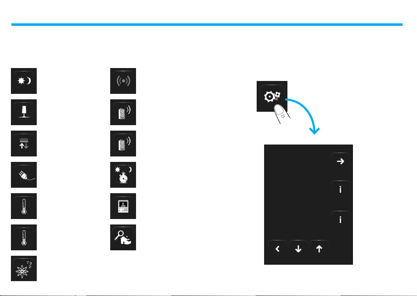
3 - Customisation
Setup ■
You can customise som e functions of the Touch Screen by accessing
this page.
Touch the icon .
The setup page will b e displayed.
ALARM
CLOCK
BEEP
CLOCK
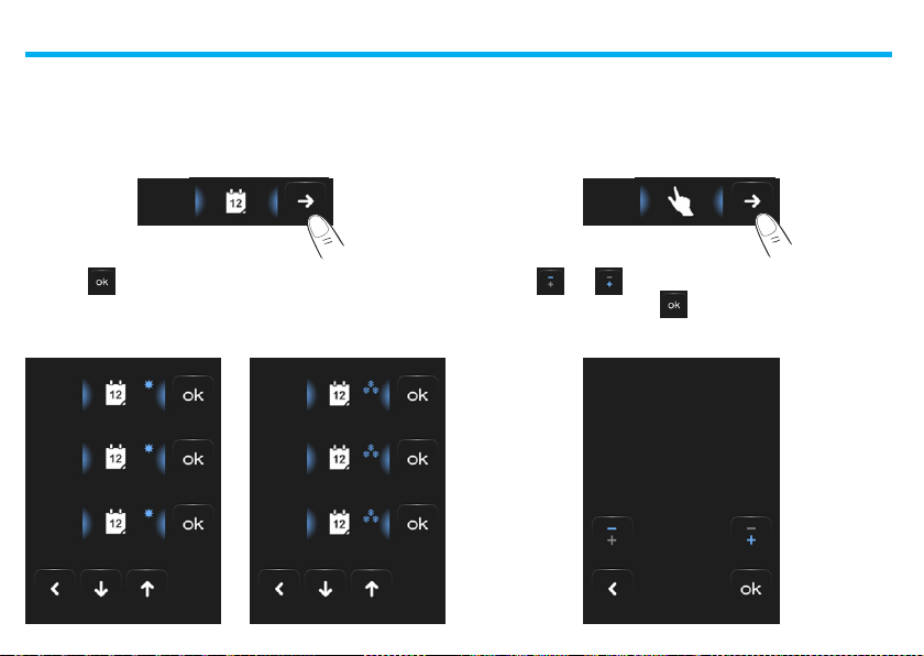
Alarm clock ✔
Touch the icon to enable or dis able the alarm clock .
Alarm clock activated
ALARM
CLOCK
Touch to disable
Touch the icon to set the alarm clo ck activation tim e.
The following page will be disp layed:
52
Alarm clock deactivated
Touch to enable
Use the arrows to set the time;
every touch will allow you to
increase or decrease by one
unit; when you press your f inger,
in cre asin g or de cre asi ng wil l
be faster.
Touch the icon to access the
selec tion page of the alarm clock
activation frequency.
ALARM
CLOCK
Page 53

3 - Customisation
Once
Always
Mon - Fri
Sat - Sun
Touch the corresponding
icon to set the alarm clock to
only once, always, M on-Frid,
Sat-S un.
If th e s oun d s ys te m i s co nf i gur ed ,
the icon at the bottom right
corner, will let you access the
configu ration page of the sound
system for the alarm clock; when
the multi- channel sound system
is required, the room must be
selected.
You will be able to choose the conditions of the sound syste m as soon
as the alarm c lock (source, amplif iers, volume) is activated.
Radio
Bedroom
The use of a multimed ia s ource with the alarm clo ck i s no t
recommended.
When the alarm clock is activated, the volume increases until it reaches
the volume s et previously.
If you touch the di splay when the alarm clock is activated, the volum e
of the am pl if ier s w il l be se t to th e cu rr ent va lue (h en ce i nte rr up tin g t he
automatic volume increase).
If there is no pressu re on the display, the a mplifier s will switch off
after t wo minutes.
53
Page 54

3 - Customisation
Beep ✔
You can enable and disabl e the audible signal wh en zones are touched.
ALARM
CLOCK
BEEP
CLOCK
If the Bee p is OFF, th e device will not emit an audible signal.
Clock ✔
Touch the icon to access the setup pa ges of the clock.
CLOCK
The following page will be disp layed:
Use the arrows to set the hour,
minutes and seconds; every touch
wi ll al low y ou to i ncr eas e or
decrease by one unit ; when you
press your finger, increa sing or
decreasi ng will be faster.
Touch the icon to access the
setup pag e of the date.
The p rogrammed time will ap pear in th e Home page and/or De fault
Page, if app lied during progra mming.
54
Page 55

3 - Customisation
Use the arrows to set the day,
month and year ; every touch will
allow you to increase or decrease
by one unit; when you press your
fing er, incre asing o r decreasing
will be fas ter.
Confirm by touching the icon
.
The programmed date w ill appear in the Ho me page a nd/or Default
Page, if app lied during progra mming.
Display ✔
Tou ch to access the disp lay control page.
The following page will appe ar:
CALIBRATION
BRIGHTNESS
SCREEN SAVER
55
Page 56

3 - Customisation
Screen cleaning
Touch the . icon. The screen is deacti vated for a certain amount of
time that ca n be set by the user using the soft ware.
The display shows the fo llowing page:
Only clean using a sof t cloth.
Do not use so lvents, abrasive, o r corrosive materials .
Do not use solvents or
corrosive materials
Time lef t for
cleaning the
screen
01 : 15
56
Page 57

3 - Customisation
Calibration ✔
To access the page which a llows you to adjust the touch accura cy of
the display, touch the icon.
CALIBRATION
The following page will be disp layed:
Touch the “cross” s ymbol on the
+
Press the cross
This procedure is ver y del icate, although it is p rovided with
pressure controls; if it is carried out incor rectly, the d evice may
no longer perceive the user ’s pressure areas, thus forcing it to
stop. In this c ase, it is necessar y to call a technician.
display, in all po sitions (5).
The icon will appear twice in
the outer ar eas of the display.
Confirm by touching t he icons.
Calibration will star t automatical ly.
Brightness
To select the S creensaver mode brightness level touch the ico n.
BRIGHTNESS
The display shows the br ightness level selection screen.
- Off.
- L ow.
- Normal.
- High.
Touch the cor responding to the de sired brightness level.
To cancel the selec tion touch the icon. To confir m the selection
touch .
57
Page 58

3 - Customisation
Screen saver
In the Setup page, touch th e icon to ac tivate the s creensaver
function:
Network
Touch the i con to disp lay the Touch Screen ne twork card setup
page:
SCREEN SAVER NETWORK
The following page will appe ar: The following page will appe ar:
- No screensaver.
- Line.
- Balls.
- Time.
- Te x t.
Touch the ico n corresponding to th e desired brightness level.
To cancel the selec tion touch the icon. To confir m the selection
touch .
Touch the ico n to enable or disable t he network card.
Touch the ico n to return to the previo us page.
H/L 468 4
Touch Screen 0
Mac
00:03:50:00:18:c7
IP
169.254.253.4
Subnet mask 255.255.0. 0
Gateway
DNS
58
Page 59

Password ✔
If the Touch Sc reen is protecte d with a password, the following pag e
will appe ar when the display is tou ched.
Us e th e n ume ri c ke ys to e nt er t he
password (default 12345)
You can cancel wi th
Confirm with
1 2 3 4 5 6 7 8
PASSWORD: *****
Change Pas sword
You c an ch ang e the e xis ting
password at any time.
The new password must have
5 figures.
Touch the icon.
If the password is correct, the
Home page will be disp layed.
PASSWORD
3 - Customisation
The display will show the page for typing in the password (see p revious page):
Type in the exis ting password;
Confirm with .
If the p assword is co rrect, you
can type in t he new passwo rd
(the password will be show n on
the display)
Car efull y m emor ize the new pas sword be fore press ing OK
because, after ena bling the pro tection, it will be indispensable
in order to us e the Touch Scre en.
Enable p rotection
You can enable the protect ion
to protec t the access to the
Touch Screen against unwa nted
actions.
By doing so, the access to the
functions will be possible only for
those who k now the password.
59
PASSWORD: 14725
Disable
PASSWORD
Enable
PASSWORD
Page 60

3 - Customisation
Version ✔
To acces s the page which allow s you to displ ay th e Touch Scr een
information, touch the icon, after 10 seconds go back to the
Setup pag e.
VERSION
672 83
FIRMWARE: 1.0.0
PIC REL: 12.40.5
HARDWARE: 3.0.3
T.S. n. 0
Forgot your password?
In thi s c as e yo u c an s ol ve the pr ob le m by di sco nn ec ti ng and re co nn ec ting the Touch Screen; after switchin g on the disp lay, you c an use the
functio ns be fore the stopping process starts . Access the customisation
menu and dis able the stopping p rocess or change the password.
No reaction to pressure
In this c ase you can solve the prob lem by d isconnecting and reco nnectin g the Touch Scre en.
Hold down a nd repeat the calibration pro cedure.
Please note: the use of ra dio devices will not guarantee
the correct indic ation of the Touch Screen status.
60
Page 61

3 - Customisation
61
Page 62

Page 63

Page 64

World Headquarters and
International Department
87045 LIMOGES CEDEX FRANCE
: 33 5 55 06 87 87
Fax: 33 5 55 06 74 55
www.legrandelectric.com
Installer stamp
reserves at any time the right to modify the contents of this booklet and to communicate, in any form
Legrand
and modality, the changes brought to the same.
 Loading...