

Page 1
BENDER
USE ARROW
AS YOUR
BENCHMARK.
TOOL
TAKE-UP
TO ARROW
GUIDE FOR OFFSETS
START BENDS AT ARROW ON TOOL
Separate degree scales are provided
for V500 and V700 raceway. Use
closed hook side for V500. Use
open hook side for V700.
Bend until inner edge of
raceway registers with
desired degree
mark.
605 Raceway Cutter for 500 Raceway –
607 Raceway Cutter for 700 Raceway – Portable single action cutters. Case hard steel blades for
clean, fast and easy square cuts every time.
605K Replacement blade for 605 Cutter –
607K Replacement blade for 607 Cutter – Case hard steel blades ensure clean, burr-free cuts.
600B RACEWAY BENDER
OPERATING INSTRUCTIONS
Installation Instruction No.: 28373R1 – Updated April 2004
The 600B consists of: Iron bender, two
sections of 3/4" [19.1mm] galvanized steel
pipe handle and extra-strong coupling.
• Bending with tool in air. Apply hand pressure as close to the tool as possible. Keep pressure
close to the groove for smoother bends and greater accuracy.
• Bending on floor. Work on hard surfaces. Avoid soft sand or deep pile carpets.
• Degree scale. One side of the tool (closed hook side) is scaled for V500 raceway.
The opposite, open hook side, is scaled for V700.
• Zero (0°) degree line. The zero degree line in bottom of groove adjacent to the hook is the
beginning point of the bend.
• Rim notches. The rim notches closest to the hook indicate exact center of a 45° bend.
Numerals “500” and “700” tell which notch to use for which size raceway.
The Raceway at left could be precut to a
49-1/2" [1257mm] length.
10" + 30" + 14" = 54"
[254mm] + [762mm] + [356mm] = [1372mm]
54" less two “GAINS” (4 1/2") = 49 1/2"
[1372mm] less [114mm] = [1257mm]
The “GAIN” on the 600B tool is 2 1/4" [57mm] for
a 90° sweep or 1 1/8" [29mm] for a 45° bend.
BENDING TIPS
BACK-TO-BACK
BENDS
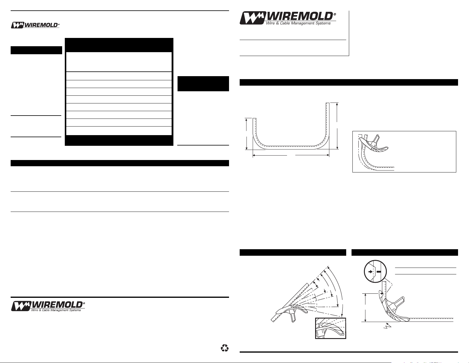
90° STUB LENGTHS
OTHER LABOR SAVING TOOLS FROM WIREMOLD
ANGLE BENDS
BENDER TAKE-UP
90° Stubs
V500 raceway 6" [152mm]
V700 raceway 6" [152mm]
STUB LENGTHS
The “GAIN” is the distance
saved by the arc of a 90° bend.
BENDING WITH THE WIREMOLD 600B BENDER
OFFSET DISTANCE ANGLE WIREMOLD
DEPTH BETWEEN BENDS OF CONDUIT
Inches [mm] Inches [mm] BENDS SHORTENS
3/8" [9.5mm] 2 1/4" [57mm] 10° —
3/4" [19.1mm] 4 1/2" [114mm] 10° —
1" [25mm] 6" [152mm] 10° 1/16"
2" [51mm] 5 1/4" [133mm] 22.5° 3/8"
3" [76mm] 6" [152mm] 30° 3/4"
4" [102mm] 8" [203mm] 30° 1"
5" [127mm] 7" [178mm] 45° 1 7/8"
6" [152mm] 8 1/2" [216mm] 45° 2 1/4"
CAT.
NO.
600B
6"
BENDS V500 AND V700
RACEWAY IN ONE
SWEEP. USE 601B
ADAPTER FOR NO.
V200 RACEWAY.
LOCATE “STAR-POINT”
➤
opposite the finish line
desired – the “star-point”
indicates where back of
the bend will lie.
➞
Knowing the “GAIN” saves time and cuts
waste. Precut raceway to the required length.
10"
14"
30"
10°
22.5°
30°
45°
60°
Measure
to Arrow
Take-Up
Floor Line
The Wiremold Company
U.S. and International:
60 Woodlawn Street • West Hartford, CT 06110
1-800-621-0049 • FAX 860-232-2062 • Outside U.S. 860-233-6251
In Canada:
850 Gartshore Street • Fergus, Ontario N1M 2W8
1-800-741-7957 • FAX 519-843-5980
© Copyright 2004 The Wiremold Company All Rights Reserved
28373R1 – Updated April 2004 – For latest specs visit www.wiremold.com
NOTE: on floor bends:
a vertical handle
indicates a 30° bend.
The Back Pusher
The Bender will grab on
in reverse to remove
an overbend.
Page 2

The Simple Box Offset
Shrinkage of
Angle Constant Offset Depth
of Bends Multiplier Inches [mm]
10° x 10° 6.0 1/16" [1.6mm]
22.5° x 22.5° 2.6 3/16" [4.8mm]
30° x 30° 2.0 1/4" [6.4mm]
45° x 45° 1.4 3/8" [9.5mm]
60° x 60° 1.2 1/2" [12.7mm]
OFFSET TABLE
Saddle Add to Center Raceway Shortens
Depth Distance Overall
Inches [mm] Inches [mm] Inches [mm]
1 [25mm] 3/16 [4.8mm] 3/8 [9.5mm]
2 [51mm] 3/8 [9.5mm] 3/4 [19.1mm]
3 [76mm] 9/16 [14.3mm] 1 1/8 [29mm]
4 [102mm] 3/4 [19.1mm] 1 1/2 [38mm]
5 [127mm] 15/16 [23.8mm] 1 3/4 [44mm]
6 [152mm] 1 1/8 [29mm] 2 1/4 [57mm]
SADDLE CENTER LOCATOR
Saddle Place Marks “B” and “C”
Depth each way from Center “A”
Inches [mm] Inches [mm]
1 [25mm] 2 1/2" [64mm]
2 [51mm] 5" [127mm]
3 [76mm] 7 1/2" [191mm]
4 [102mm] 10" [254mm]
5 [127mm] 12 1/2" [318mm]
6 [152mm] 15" [381mm]
Offset Place Two Marks Shrink Table*
Depth on Raceway
(Raceway Shortens)
Inches [mm] Inches [mm]
1 [25mm] 2 5/8" [67mm] apart 3/16 [4.8mm]
2 [51mm] 5 1/4" [133mm] apart 3/8 [9.5mm]
3 [76mm] 7 3/4" [197mm] apart 9/16 [14.3mm]
4 [102mm] 10 1/2" [267mm] apart 3/4 [19.1mm]
5 [127mm] 13" [330mm] apart 15/16 [23.8mm]
6 [152mm] 15 1/2" [394mm] apart 1 1/8 [29mm]
7 [178mm] 18 1/4" [464mm] apart 1 5/16 [33mm]
8 [203mm] 20 3/4" [527mm] apart
1 1/2 [38mm]
Position the tool on raceway
so the “STAR-POINT”
symbol is opposite the
finish line desired. The
STAR-POINT indicates
where the back of any
angle bend will lie
(1° to 90° inclusive).
BACK-TO-BACK BENDS
OFFSET TABLE
OFFSET BY TRIANGULATION
“3 BEND” PIPE SADDLES
BENDING WITH THE WIREMOLD 600B BENDER
The Star-Point
Finish Line
WITH 22.5° BENDS
To make a 3/8" [9.5mm] deep offset in either
V500 or V700 Raceway:
Place two marks on raceway 2 1/4" [57mm]
apart and make 10° bends as shown.
* The “shrink table” column tells where to place the first mark. If stringing raceway towards an obstruction,
place the first mark on raceway beyond edge of obstruction distance shown in shrink table. If offsetting
away from obstruction ignore shrink.
BEND WITH MARK ON RACEWAY OPPOSITE ARROW ON TOOL
Shrink Column above indicates where to
place the first mark. The 10" offset
illustrated (with 45° bends) would shorten
the raceway 10 x 3/8" or 3 3/4" [254mm x
9.5mm x 95mm]. Therefore place 1st
mark 3 3/4" [95mm] beyond the edge of
beam to allow for this shrink.
Example:
Making a saddle in 500 or
700 raceway over a 2"
[51mm] diameter. pipe.
Use this table to locate
center mark “A”
Use the table below to locate
marks “B” and “C”.
FORMULA:
Offset Constant Distance
Depth Multiplier Between Bends
X=
EXAMPLE:
To offset under 10" [254mm] beam:
1. Select angle of bends.
2. Multiply offset depth by
proper Constant Multiplier.
3. Depending on the angle of
bends, the distance between
bends for a 10" [254mm]
offset is...
STEP ONE
STEP TWO
Make a 45° bend with “A” opposite deepest rim notch on tool.
STEP THREE
Make a 22.5° bend at “B” (mark
“B” at zero degree line on tool)
STEP FOUR
Make a 22.5° bend at “C” (mark
“C” at zero degree line on tool)
STEP FIVE
Note: The center on a “3 Bend” Saddle
shifts (shortens) 3/16" [4.8mm]
for every inch of saddle depth.
22.5° 30° 45° 60°
10" BEAM
2.6 2.0 1.4 1.2
26" 20" 14" 12"
Before 15 3/8"
After 15"
Add to Center Distance 3/8"
3/4"
Total
Shrink
2" Dia.
3/8" Center Shrink
BA C
22.5° 45° 22.5°
5" 5"
22.5° 22.5°
0° Line0° Line
}
}
}
Mounting Surface
3/8" [9.5mm]
Offset
2 1/4"
[57mm]
10°
Offset Place Two Marks Shrink Table*
Depth on Raceway
(Raceway Shortens)
Inches [mm] Inches [mm]
3 [76mm] 6" [152mm] apart 3/4 [19.1mm]
4 [102mm] 8" [203mm] apart 1 [25mm]
5 [127mm] 10" [254mm] apart 1 1/4 [32mm]
6 [152mm] 12" [305mm] apart 1 1/2 [38mm]
7 [178mm] 14" [356mm] apart 1 3/4 [44mm]
8 [203mm] 16" [406mm] apart
2 [51mm]
9 [229mm] 18" [457mm] apart 2 1/4 [57mm]
10 [254mm] 20" [508mm] apart 2 1/2 [64mm]
WITH 30° BENDS
Offset Place Two Marks Shrink Table*
Depth on Raceway
(Raceway Shortens)
Inches [mm] Inches [mm]
5 [127mm] 7" [178mm] apart 1 7/8 [48mm]
6 [152mm] 8 1/2" [216mm] apart 2 1/4 [57mm]
7 [178mm] 9 3/4" [248mm] apart 2 5/8 [67mm]
8 [203mm] 11 1/4" [286mm] apart 3 [76mm]
9 [229mm] 12 1/2" [318mm] apart 3 3/8 [86mm]
10 [254mm] 14" [356mm] apart 3 3/4 [95mm]
11 [279mm] 15 1/2" [394mm] apart 4 1/8 [105mm]
12 [305mm] 16 3/4" [425mm] apart 4 1/2 [114mm]
13 [330mm] 18 1/4" [464mm] apart 4 7/8 [124mm]
14 [356mm] 19 3/4" [502mm] apart 5 1/4 [133mm]
15 [381mm] 21" [553mm] apart 5 5/8 [143mm]
WITH 45° BENDS
 Loading...