

LEGRAND 766 21, 766 22, 4 131 05, 766 20, 431 00 Installation And Usage Manual
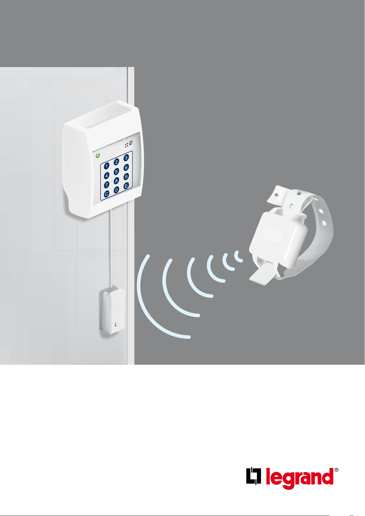
SECURE WANDERING
4
7
C
1
5
8
0
2
6
9
E
3
SYSTEM
INSTALLATION AND USAGE GUIDE


Contents
2 INSTALLATION PRINCIPLE
2 System description
3 DEVICE PRESENTATION AND
INSTALLATION
3 Secure wandering system
6 Secure wandering system - auxiliary elements
7 STANDALONE INSTALLATION
7 Example installation
9 Wiring - controllers and antennae
10 Operating modes
11 SYSTEM INSTALLATION
11 Example installation
13 Wiring - controller/antennae and door unit
14 Operating modes
15 COMMISSIONING
15 Factory settings
16 Parameter setting
18 Adjusting the antennae
19 OPERATION
19 Operation in day mode (surveillance)
20 Operation in night mode (intruder)
21 Illuminated signals
22 CHARACTERISTICS
22 Specifications
23 USAGE CODES
23 Control code

2
Installation principle
SYSTEM DESCRIPTION
Safety instructions
This product must be installed in accordance with the
installation regulations and preferably by a qualified
electrician. Incorrect installation and operation may
lead to the risk of electric shock or fire. Read the
instructions and consider the product's specific
assembly location before carrying out the installation.
Do not open, remove, alter or modify the device unless this
is specifically stated in the instructions. Legrand products
must be opened and repaired exclusively by personnel
trained and authorised by Legrand. Any unauthorised
opening or repair voids all liability, replacement rights and
warranties.
Only use Legrand brand accessories.
Operating environment
- This device complies with the directives related to
exposure to radioelectric frequencies when used under
the normal conditions described in the user manual.
Follow the installation instructions described in the
manual.
- Depending on the configuration, this device regularly
transmits radio frequency radiation, the frequency and
power of which comply with ARCEP recommendations.
Using it in an industrial or hospital environment does
not generally pose any problem. However, using it
close to certain sensitive electronic systems may lead
to interference. Please ensure that installation of this
device is limited when in close proximity to any other
electronic equipment.
Operation
The secure wandering system is a system that allows
any potential escape attempts by confused patients to
be controlled.
Each exit under surveillance is fitted with a standalone
controller which alerts staff when a person wearing a
special wristband tries to go through it. In the event that
there are no supervisory staff near the exit this information
can be transmitted to the BUS/SCS nurse call unit using a
door unit Cat. No. 766 06 configured for this function.
This way nurses receive information on the escapee's
identity and on the door used.
The system can operate using two modes:
• Surveillance mode: An alarm is activated when the
wearer of a wristband is close to the exit and this exit
is open.
• Intruder mode: An alarm is activated when an exit
is opened
Switching from one mode to the other is done manually by
entering a special code into the controller keypad.
The staff have a chaperone code which allows a wristband
wearer to be let through an exit under surveillance
without triggering an alarm.
Two control outputs allow:
• The exit to be locked once a wristband is detected in the
vicinity (provide an electromagnetic lock*).
• An audible or illuminated warning signal to be triggered
when an escape alarm is activated.
* Product to be ordered separately (see p. 4)
3
Device presentation and installation
4
7
C
1
5
8
0
2
6
9
E
3
1
2
3
4
5
6
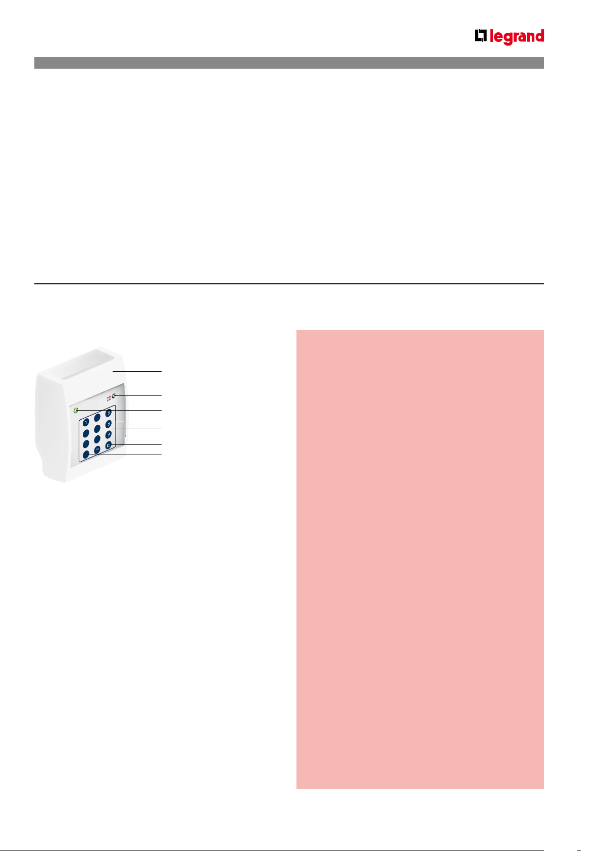
SECURE WANDERING SYSTEM
This system is used to signal crossing of a door threshold by a resident fitted with a wristband Cat. No. 766 20.
It works with door unit Cat. No. 766 06 configured for secure wandering and allowing acknowledgement.
Door controller Cat. No. 766 22
1 Wristband activation magnet
2 Detection LED
3 Status LED
4 Coded keypad
5 Enter key
6 Cancel key
Normally situated close to the exit, this controller is the
heart of the system.
All auxiliary elements are connected to it.
A 12-button keypad is used to configure and
activate special functions (mode changes, alarm
acknowledgement, etc.).
A buzzer acts as a warning if an escape is detected.
The door controller retrieves the information from antenna
Cat. No. 766 21 and from door contact Cat. No. 431 00 and,
depending on its usage mode, either triggers a nurse call
or locks the door.
When the door is locked it can be unlocked using special
codes.
The coded keypad captures the wristband signal when a
predefined door is crossed.
Requires a modular 12 V= power supply
(Cat. No. 4 131 05).
Technical characteristics
IP 20 - IK 04
• Operating temperature:
0°C to +45°C
• Power supply:
- 12 V=
- 500 mA
• Illuminated signals:
- System power on
- Intruder mode
- Wristband detection
• Audible signals:
- Alarm
- Alarm suppressed by chaperone code
• Functions that can be accessed via the keypad:
- Reset alarms
- Chaperone
- Changeover between surveillance/intruder modes
- System parameter settings
• Controller inputs:
- Adjustable connection
- Volt-free contacts
- Voltage detection
5-24 V=
50 mA to 24 V=
- Door contact (NO/NC)
- Chaperone contact (NO)
- Alarm acknowledgement (NO/NC)
- Mode selection
- Panic alarm (NO)
• Volt-free contact outputs:
- Locking: 1 A - 24 VA/60 V= max
- Alarm: 1 A – 24 VA/60 V= max
• Cable type for link with door unit (system solution):
2 x 9/10th pairs
4
Device presentation and installation (continued)
1
2
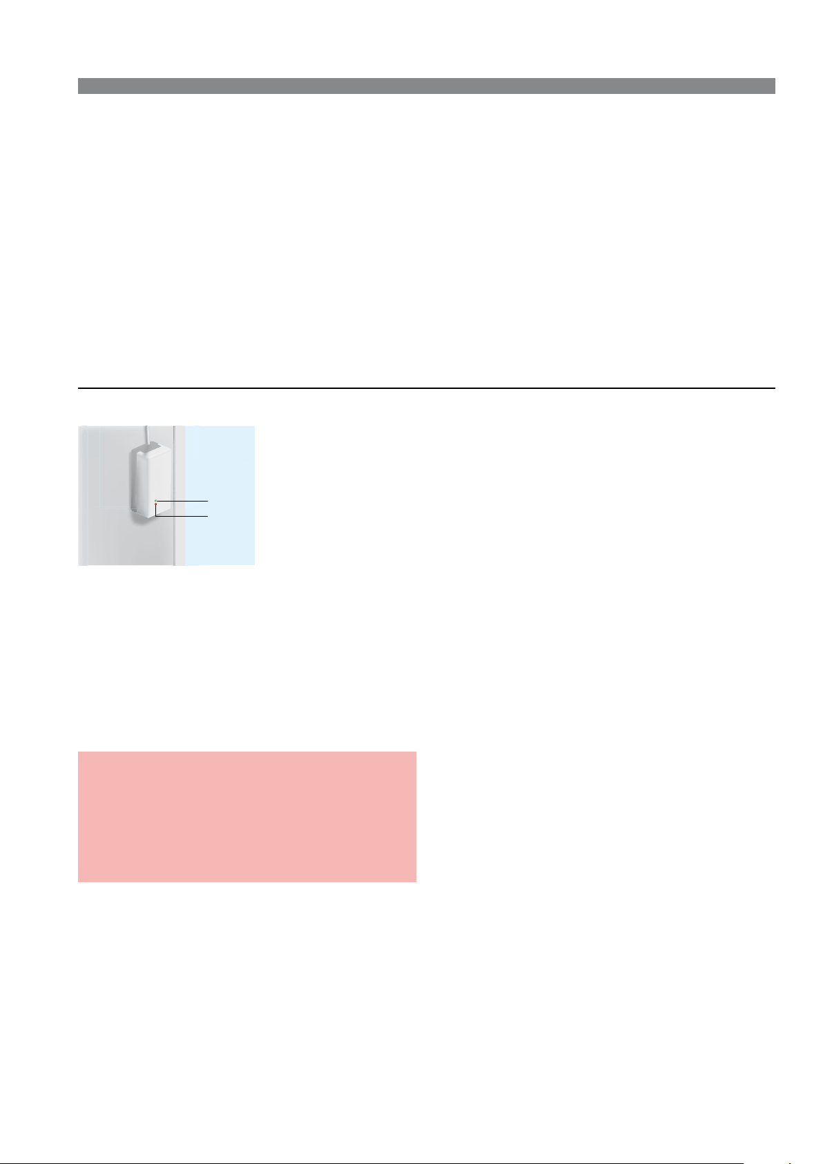
SECURE WANDERING SYSTEM (CONTINUED)
Antenna Cat No. 766 21
1 Status LED
2 Detection LED
Placed as close to the exit as possible, ideally 50 cm from the ground at the side of the door latch, this element detects the
presence of a wristband Cat. No. 766 20 and informs the controller Cat. No. 766 22.
The sensitivity and therefore the detection radius (around 1 to 15 m) can be set easily using a screwdriver.
A green indicator light indicates that the antenna power is on.
A red indicator light flashes when a wristband is in the detection zone (see setting the antenna).
The antenna activity is permanently checked by the controller.
Technical characteristics
• Power supply: via door controller Cat. No. 766 22
• Dimensions (H x W x D): 50 x 100 x 40 mm
• Screwed onto the wall
• IP 20 - IK 04
• Operating temperature: +0°C to +50°C
• Cable type (to controllers 766 22): 2 x 9/10th pairs
5
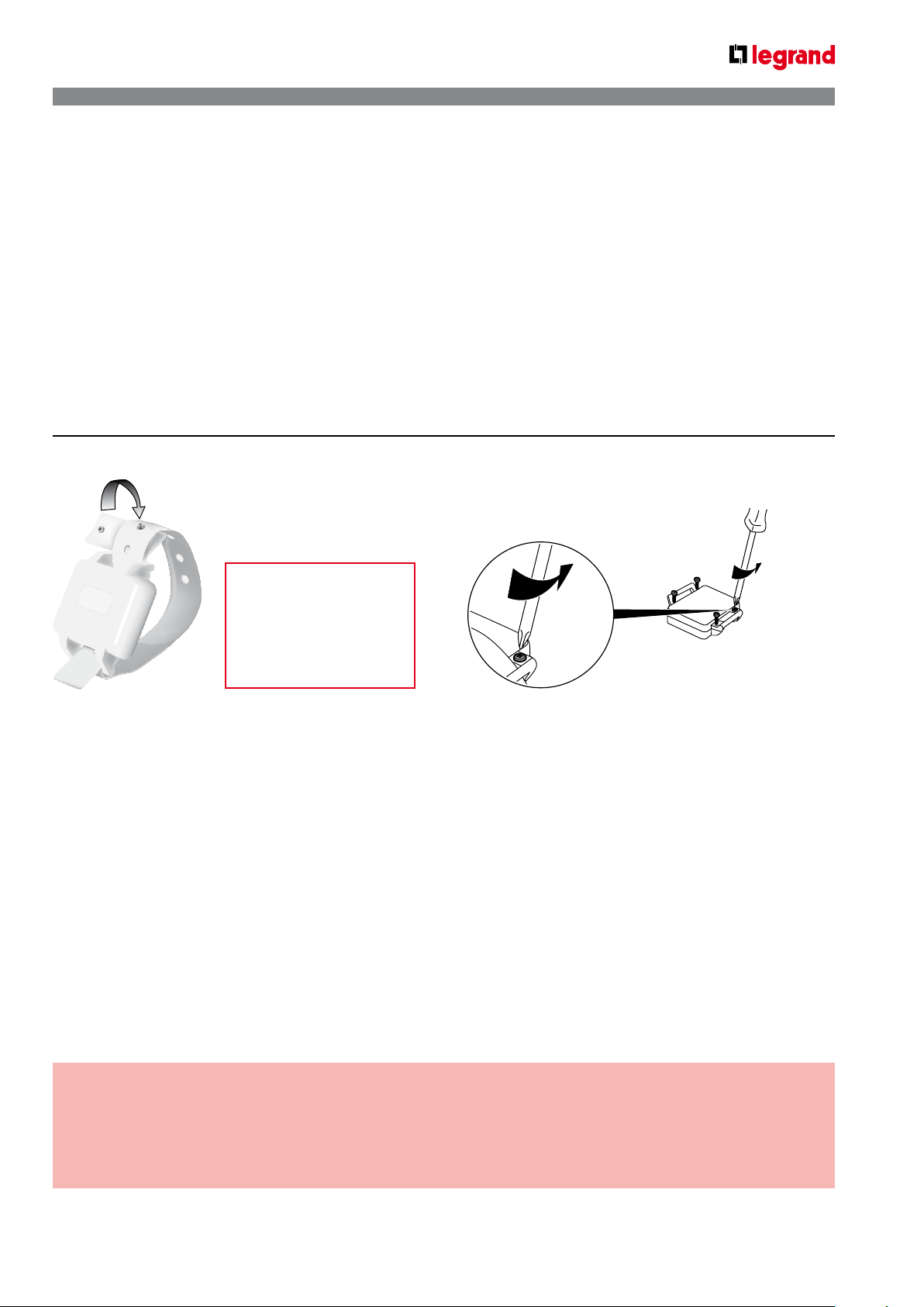
Wristband Cat. No. 766 20
Activated or deactivated
by passing a magnet
over the device.
To be performed close
to the controller
Cat. No. 766 22.
Worn on the wrist or the ankle, this waterproof wristband is fitted with eyelet closures preventing the person under
surveillance from taking it off.
These wristbands are made of anti-allergy plastic that is capable of being in continuous contact with the skin.
The battery has an expected lifetime of more than one year (although replacing the batteries every year is
recommended).
The weatherproof seal (IP 55) allows residents to take baths and showers.
The wristbands can also be cleaned by placing them in an alcohol bath for 5 minutes.
Wristbands must be removed in the following cases:
- If they are faulty or the battery is dead
- When the resident leaves
- When the resident undergoes an MRI (magnetic resonance imaging) exam
To remove the wristband, cut it with a pair of round-end scissors.
When a wristband is immobile it switches to low-consumption mode. This allows the standalone capacity of the battery
to be increased to a maximum 4 years when stored.
Once movement is detected the wristband switches immediately to operational mode.
Technical characteristics
• IP 55 - IK 08
• Anti-allergy
• Frequency: 869.85 MHz
• Tx: 869.85 MHz - Rx: 446.525 MHz
• Radiated power: < 10 mW
• Power supply: 1 x CR2450 3 V battery
• Standalone operation: 18 months with normal usage
• Dimensions (mm): 33 x 40 x 17
• Weight: 28 g in working order
6
Device presentation and installation (continued)
Sensor
DOOR
766 22
SECURE WANDERING SYSTEM - AUXILIARY ELEMENTS
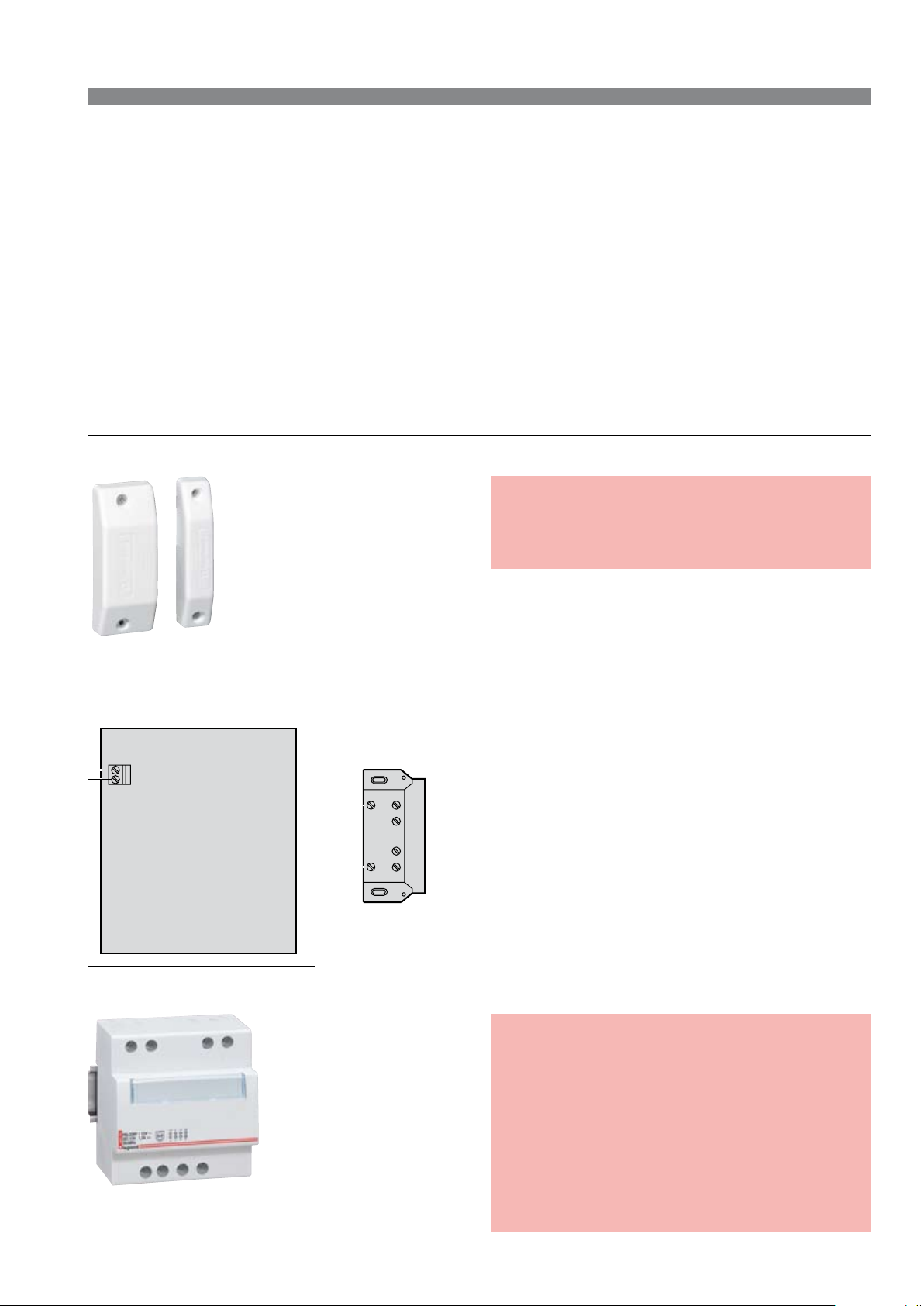
Door contact Cat. No. 431 00
Technical characteristics
• IP 41 - IK 02
• Operating temperature: -10°C to +70°C
• Cable type (to controllers 766 22): 1 x 9/10th pairs
The magnetic opening sensor must be connected to the "DOOR" input of controller 766 22.
An escape alarm is only generated on the double condition that a wristband and opening of the door are both detected.
Power supply Cat. No. 4 131 05
Technical characteristics
• Power: 15 W
• Operating voltage: 12 V
• Current: 1,25 A
• Dimensions: 5 x 17.5 mm modules
• Cable type (to controller 766 22):
2 x 1.5 mm
• Class II
• Double operating terminal
• Protected by PTC against overloads and
short-circuits
2
 Loading...