

Page 1
87045 LIMOGES Cedex
Telephone: (+33) 05 55 06 87 87 - Fax: (+33) 05 55 06 88 88
Modular fuse carriers for
photovoltaic applications
Do not open
under load
414 681 414 682
1. GENERAL FEATURES
1-1 Brief description
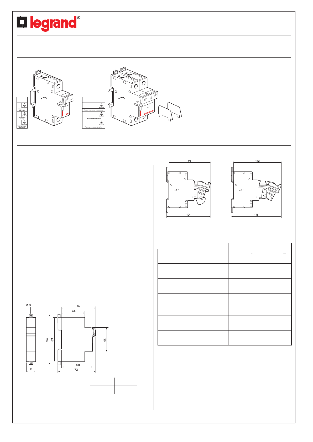
- Single pole (1P) and 2-pole (2P) photovoltaic (PV) fuse carrier
for isolating and protecting DC circuits from PV panels for
applications up to 1000 V.
- For 10 x 38 mm cylindrical fuses
- Supplied with dividers (4146 82) and safety labels:
“Do not operate under load”
Do not operate under load
Catalogue number(s): 4146 81/82
CONTENTS PAGES
1. General features
2. Overall dimensions
3. Technical features
4. Materials
5. Installation
6. Conformity
7. Setup
8. Maintenance
9. Accessories
2. OVERALL DIMENSIONS (continued)
1
1
1
2
2
2
2-3
3-4
4-5
1-2 Use
- Use recommended according to recommendations in guide
UTE C 15-712-1
- Use with fuses specifically designed for the DC side of
PV applications
Recommended use:
- 1P fuse carrier: For installations with polarised PV panels
(with earthing of one of the polarities), protection of the poles
not connected to earth for each PV string
- 2P fuse carrier: For protection of both poles of each string
of non-polarised PV panels
2. OVERALL DIMENSIONS
3. TECHNICAL FEATURES
Operating voltage (Ue)*
Operating current (le)
Number of protected poles
Utilisation category
Max. short-circuit current
(Isc)
Rated impulse withstand
voltage Uimp
Degree of pollution
Usage temperature
Storage temperature
Mechanical performance
Protection
4146 81 4146 82
1000 V
20 A
1
1000 V
20 A
2
DC 20B DC 20B
50 kA
6 kV
2
-5°C +40°C
50 kA
6 kV
2
-5°C +40°C
-25°C +70°C -25°C +70°C
IK04 IK04
IP2X IP2X
1 pole
17.7B
Technical data sheet: F01248EN/01 Updated on: Created on: 13/01/2012
2 poles
35.5
2013-07-02
1/5
Page 2
Modular fuse carriers for
photovoltaic applications
Catalogue number(s): 414 681/82
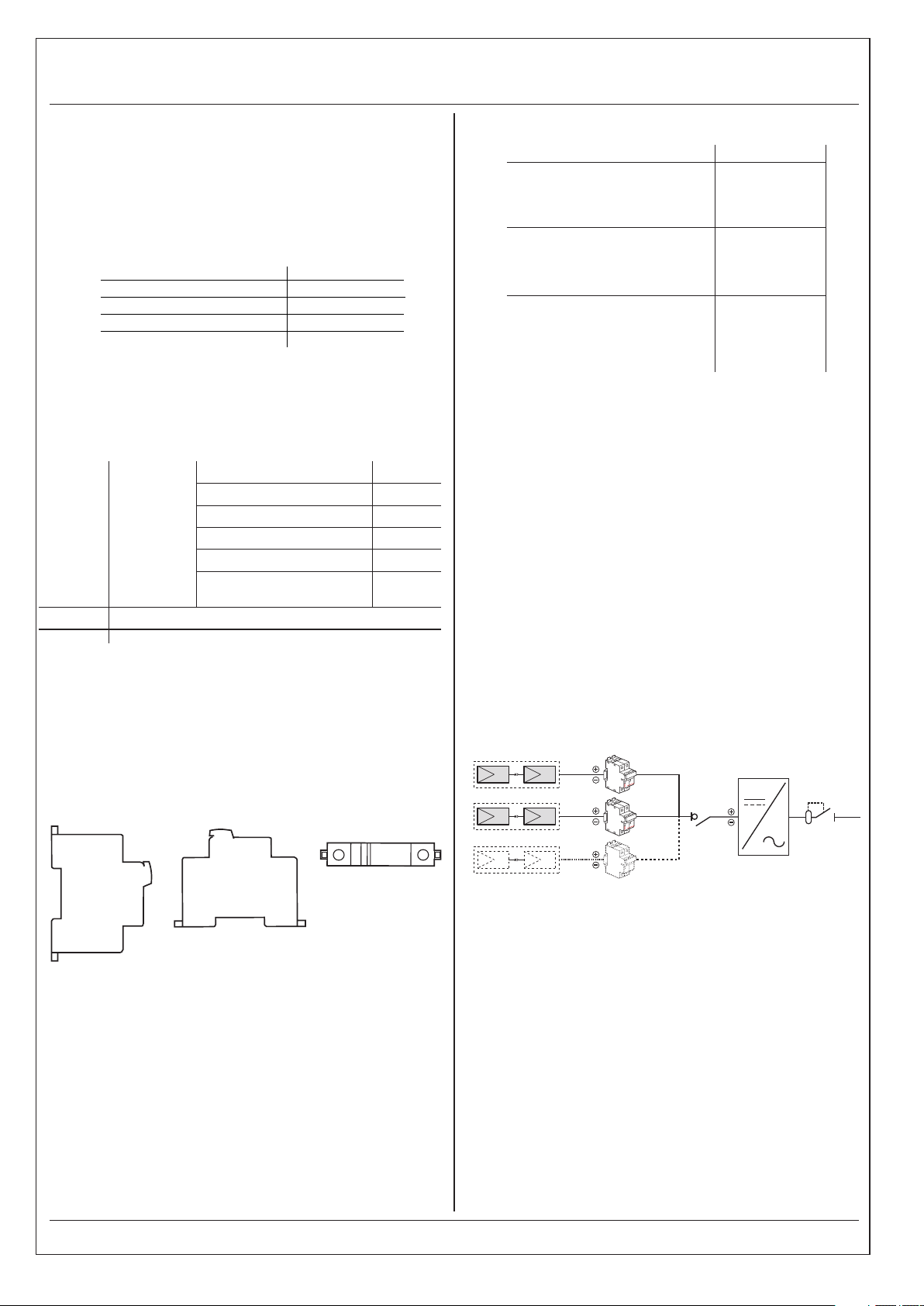
3-1 APPARATUS DOWNGRADING
It can be justified to downgrade the apparatus when the conditions
of use become more hard :
- Room temperature higher than 35° C : To downgrade the fuse
of a grade by 10° C (UTE guide C 20-051, NF IEC 60 943,
guide to over heating)
- Juxtaposed apparatus and simultaneous operations
To apply to the base rated current the corresponding coefficient :
Number of juxtaposed poles Coefficient
1 - 2 or 3 pôles 1
4 - 5 or 6 pôles 0,8
7 - 8 or 9 pôles 0,7
10 pôles and more
(NF C 63-421 / NF EN 60439-1, table 1)
Permanent mode (more than 8 hours per day) : It can be
to downgrade the base of a size.
4. MATERIALS
Density
Max. tensile stress
Bending modulus
Glow-wire
Oxygen index
Colour
Zinc-plated bichromate steel
Copper with silver track
Housing
Screws
Contacts
Reinforced
polybutylene
terephthalate
0,6
1.62 to 1.70
> 100 MPa
> 9.50 GPa
960°C/5 s
> 30
Grey
RAL 7035
5. INSTALLATION (continued)
1P/2P
Permitted conductors
- Flexible with cable ends
- Flexible
Tools required
-
Flat screwdriver
- Phillips screwdriver
Tightening torque
- Min.
- Max.
- Recommended
Cage terminals, with pozidriv mixed disengageable
and captive screws
6. CONFORMITY
Products conform to standards:
- EN/IEC 60269-1
- EN/IEC 60947-3: classification DC20B
(Do not operate under load)
Comply with the installation obligations and recommendations
of standard NF C 15-100 and guide UTE C 15-712-1
7. SETUP
7-1 General principle
-
1.5 to 10 mm²
4 to 10 mm²
-
Ø 4 to 5.5 mm
PZ2
-
1.8 Nm
3 Nm
2.2 Nm
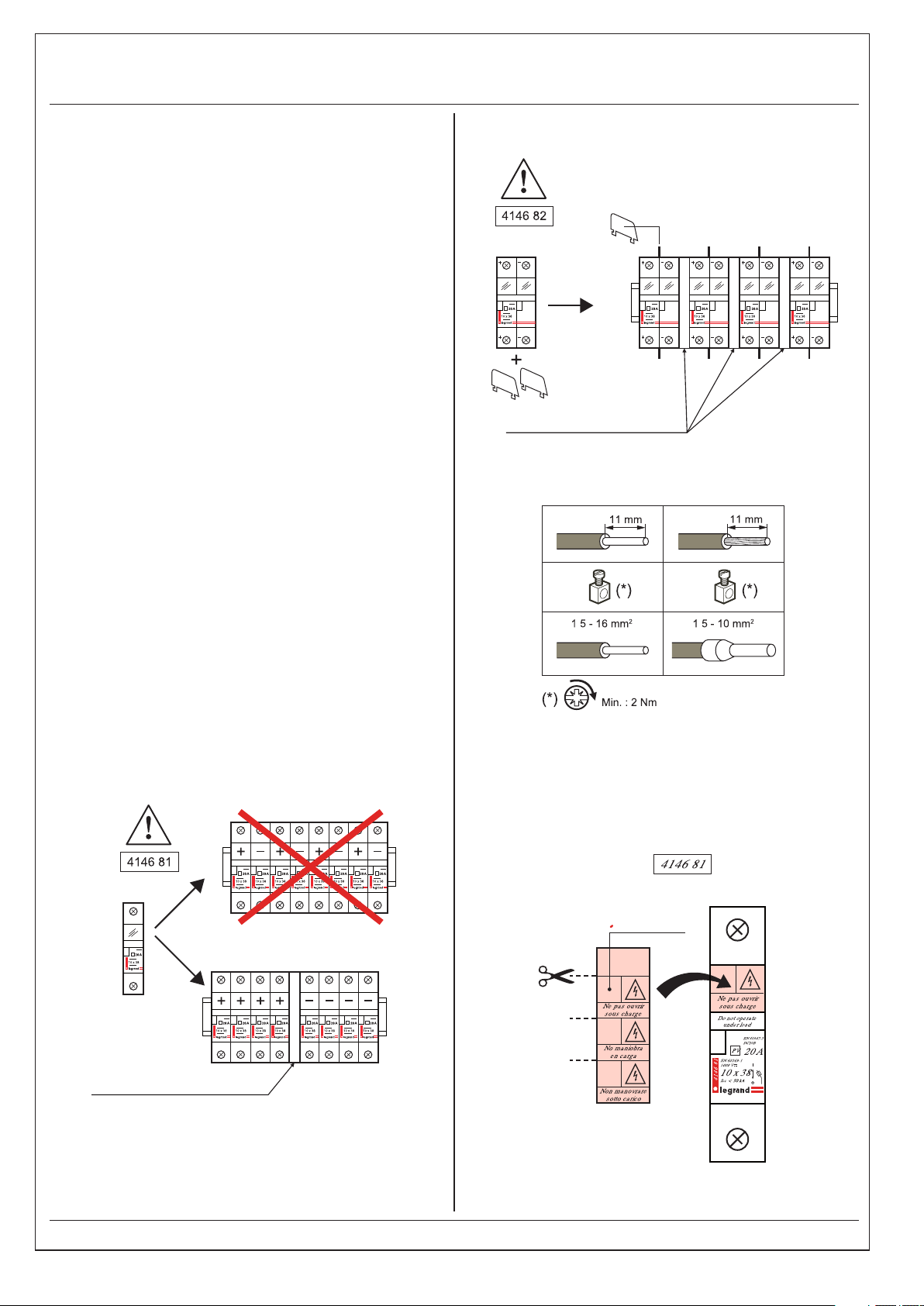
5. INSTALLATION
Mounting: - On EN 50.022 or EN 60.715 symmetrical rail
Mounting:
disengaged
Power supply: Via the top or the bottom
Operating position: Vertical or horizontal or side
Subject to use fuses Legrand brand
Connection: “Solar” cables
- With Ø 3 screws on plate at each end with clips
7-1-1 Installations with non-polarised PV panels
For PV installations based on the use of non-polarised panels,
neither of the polarities of the panels is connected to earth.
Both the polarities of the panels must be protected.
2013-07-02
Created on: 13/01/2012Technical data sheet: F01248EN/01 Updated on:
2/5
Page 3
Modular fuse carriers for
photovoltaic applications
Catalogue number(s): 414 681/82
7-1-2 Installations with polarised PV panels
For PV installations based on the use of polarised panels,
one of the polarities of the panels is connected to the earth
of the installation (in accordance with the recommendations
of the manufacturers of the PV panels)
For each string of polarised panels, the conductors must be
protected as follows:
- Conductors not connected to earth: protection by single pole
fuse carrier
- Panels with direct connection to earth (direct earthing with no
intermediate resistor): protection of all these conductors with a
single fuse and a single pole fuse carrier
Cables connected to earth:
Polarised panels must be earthed at a single point for all the
conductors of the PV generator (PV strings associated with the
same inverter or the same MPPT). This point must be located
upstream of the inverter's breaking and isolating device
(isolating switch) in order to maintain the earthing of the panels
even during maintenance of the inverter and the panels.
The cross-section of the earthing conductor must be
appropriate for the protection device breaking the fault current
(min. 4 mm² copper or equivalent). The rating of the protection
device must be chosen according to the technology of the
PV modules and the area of the PV array.
- 2-pole fuse carrier
Cat. No. 4 063 07 or 10 mm min.
7-3 Connections
.
.
7-2 Usage limits
Single pole fuse carrier
Cat. No. 4 063 07 or 10 mm min.
7-4 Labelling and safety markings
In accordance with guide UTE C 15-712, a “do not open under
load” label must be affixed to the fuse carriers
1P fuse carrier
String number
Do not open
under load
Technical data sheet: F01248EN/01 Updated on:
2013-07-02
Created on: 13/01/2012
3/5
Page 4
Modular fuse carriers for
photovoltaic applications
Catalogue number(s): 414 681/82
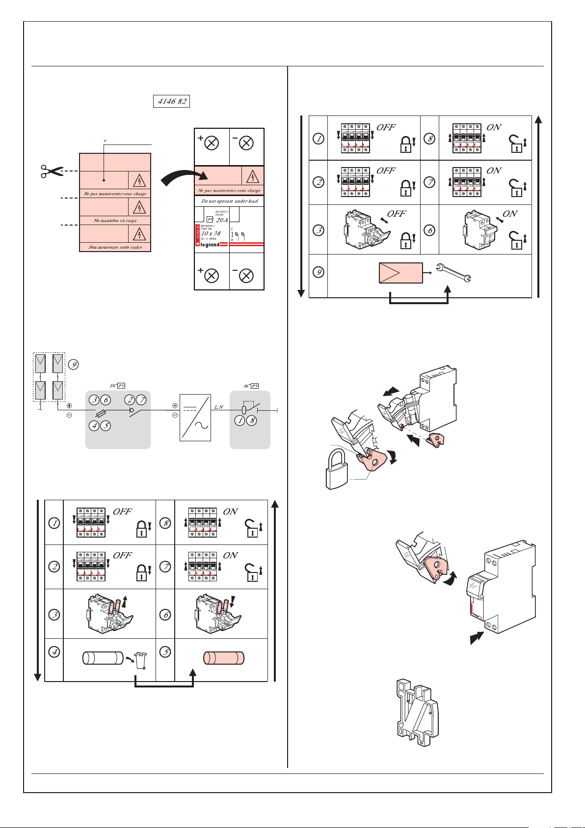
- 2P fuse carrier
Do not operate under load
8. MAINTENANCE
Maintenance on panels
String number
9. ACCESSORIES
9-1 Padlocking accessory Cat. No. 057 99
Replacement of fuses
➊
Ø 4
➋
Ø 4 to 6
Ø5 mm padlock Cat. No. 4 063 13
Ø6 mm padlock Cat. No. 227 97
9-2 Separation module (0.5 module)
➌
➊
➋
Cat. No. 4 063 07
2013-07-02
Created on: 13/01/2012Technical data sheet: F01248EN/01 Updated on:
4/5
Page 5
Modular fuse carriers for
photovoltaic applications
Catalogue number(s): 414 681/82
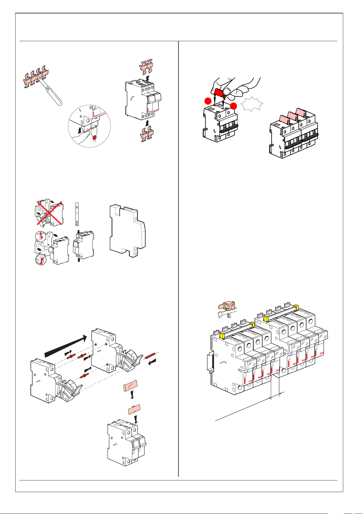
9-3 Sealable screw cover (4 separable poles) Cat. No. 4 063 04
Cat. No. 4 063 04
➊
➋
➌
➍
9-4 Auxiliary
N/C + N/O early break and signalling auxiliary
5 A – 250 V (0.5 module)
Cat. No. 057 96
9-6 Pole separation divider
Cat. No. 4 063 05
1
9-7 Universal prong-type busbars 4 049 26/37
Can be used up to 1000 V to group together strings of
photovoltaic panels with same polarity on the DC side with
single pole fuse carriers Cat. No. 4146 81.
CLICK
2
9-5 Joining assembly
2-pole Cat. No. 057 92
3-pole Cat. No. 057 93
4-pole Cat. No. 057 94
➋
➊
➎
➍
Note: The ends of the busbars must be equipped with the
protection accessory Cat. No. 4 049 89.
Insert a spacing module Cat. No. 4 063 07 between
2 consecutive units with different polarities.
4 049 05
➌
or 10 mm min.
4 063 07
Cat. No.
2013-07-02
Created on: 13/01/2012Technical data sheet: F01248EN/01 Updated on:
5/5
 Loading...