

Page 1
87045 LIMOGES Cedex
Technical data sheet
Telephone: + 33 5 55 06 87 87 – Fax: + 33 5 55 06 88 88
Isolating switch DX3≤ 63 A
direct current, 800V
1. DESCRIPTION - USE
. Modular isolating switch (IS) for the control of electrical circuits
supplied with direct current. This isolating switch can be used for
photovoltaic applications.
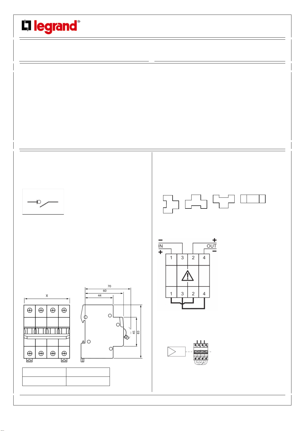
Symbol:
Cat. n°(s) : 4 142 21 / 23 / 24 / 26
CONTENTS PAGES
1. Description - Use ................................ 1
2. Range................................................. 1
3. Overall dimensions ............................. 1
4. Preparation - Connection .................... 1
5. General Characteristics ...................... 2
6. Compliances and approvals................ 4
7. Auxiliaries and accessories................. 4
4. PREPARATION - CONNECTION
Mounting:
. On symmetrical EN 60.715 rail or DIN 35 rail
Operating positions:
.Vertical Horizontal Upside down On the side
2. RANGE
Polarity:
. 2P in 4 modules.
. 2 modules per pole (2 x 17,7 mm = 35,4 mm).
Rated currents In:
. 16 A / 25 A / 32 A / 63 A.
Rated voltage:
. 800 V DC (direct current)
3. OVERALL DIMENSIONS
Power supply:
. Only from the top like it is shown in the wiring diagram on right side
of the device.
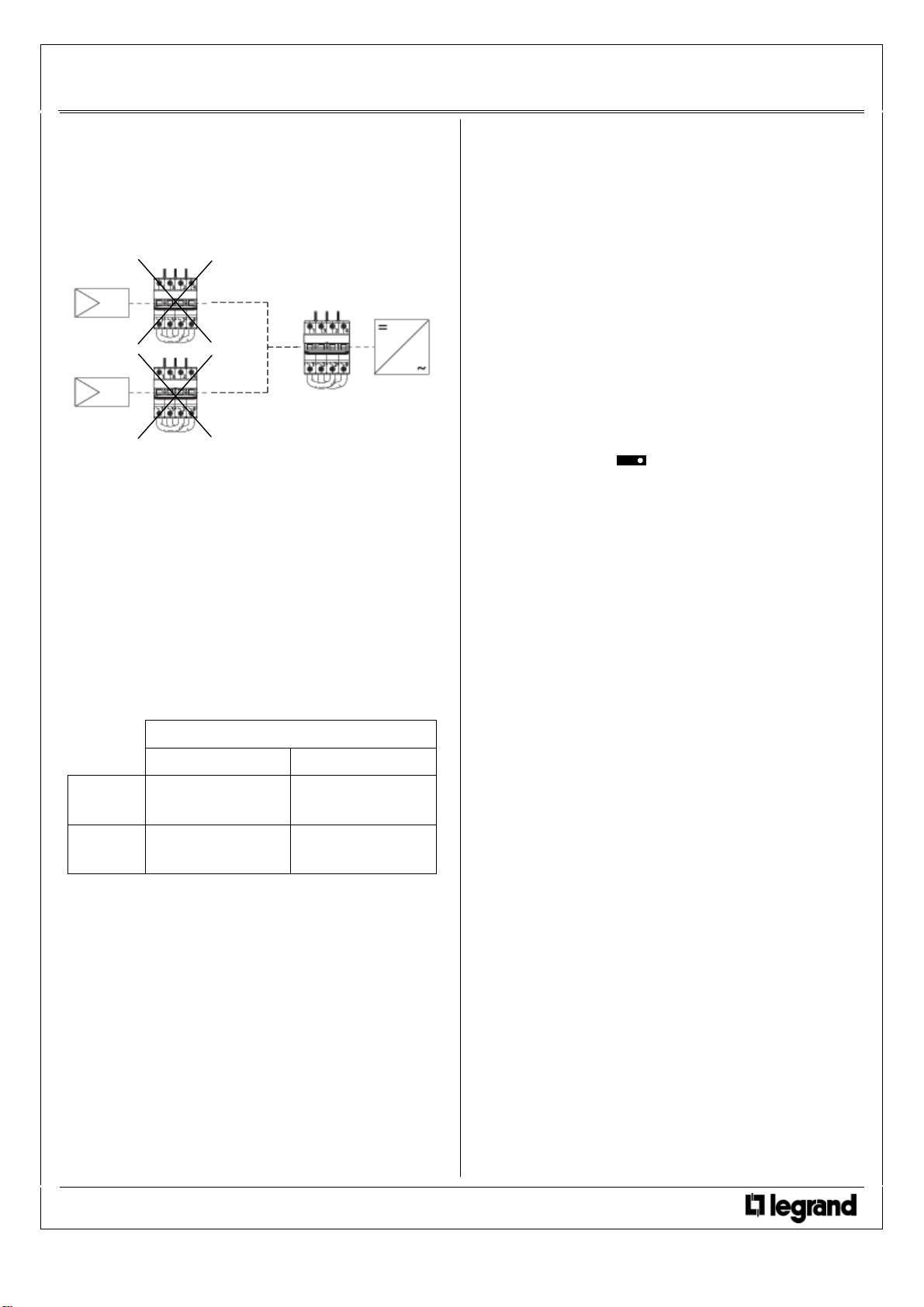
Warning : isolating switches 32 A (Cat. No. 4 142 24) and 63 A (Cat.
No. 4 142 26) do not accept « reverted currents ». In a photovoltaic
installation, they cannot be installed close to the solar panels but
only close to the UPS.
N° of Poles “X” (mm)
2P 70,8 mm
: F01282EN/02 Updated : 24/08/2016 created : 7/10/2011
1 / 4
Page 2
Isolating switch DX3≤ 63 A
Technical data sheet
direct current, 800V
Cat. n°(s) : 4 142 21 / 23 / 24 / 26
4. PREPARATION - CONNECTION
(continued)
Supply and localisation in the installation:
Warning: isolating switches 32 A (Cat. No. 4 142 24) and 63 A (Cat.
No. 4 142 26) do not accept « reverted currents ». In a photovoltaic
installation, they cannot be installed close to solar panels to control
groups of panels but only close to the UPS to control the whole
group of panels.
Terminal depth:
. 14 mm.
. It is necessary to use the insulating shields between terminals.
. The shields are delivered with this isolating switch.
Screw head:
. Mixed, slotted and Pozidriv n° 2.
4. PREPARATION - CONNECTION
(continued)
Labelling:
. Circuit identification by way of a label inserted in the label holder
situated on the front of the product.
5. GENERAL CHARACTERISTICS
Marking on the front side:
. By permanent ink pad printing - category of use DC21B.
- relevant standard n° IEC 60947-3.
- rated current in amps (A).
- rated voltage in volts (V).
- cat. n° and logo
- grand name Legrand.
- I and O with a double arrow.
- electrical diagram.
Recommended tightening torque:
. 3 Nm.
Recommended tools:
. For the terminals: screwdriver Pozidriv n°2.
. For attaching or removing the DIN rail: screwdriver slotted 5.5 mm
(6 mm maximum).
Conductor type:
Copper cable
Without ferrule With ferrule
Rigid wire
Flexible
wire
1 x 1,5 mm² to 35 mm²
2 x 1,5 mm² to 16 mm²
1 x 1,5 mm² to 25 mm²
2 x 1,5 mm² to 10 mm²
-
1 x 1,5 mm² to 25 mm²
Manual actuation of the IS:
. Ergonomic 2-position handle
- “O-OFF”: Device open
- “I-ON”: Device closed
Display of contacts status :
. By the position of the handle and printings
- “O-OFF”: = contacts open
- “I-ON”: = contacts closed
Marking on the Left side:
. By laser:
- wiring diagram
Sealing:
. Possible in the open or closed positions
Locking:
. With padlock (Cat. No. 0 044 43 or 0 227 97), whit support for
padlock (Cat. No. 4 063 03) in the open position.
: F01282EN/02 Updated : 24/08/2016 created : 7/10/2011
2 / 4
Page 3
Isolating switch DX ≤ 63 A
Technical data sheet
direct current, 800V
Cat. n°(s) : 4 142 21 / 23 / 24 / 26
5. GENERAL CHARACTERISTICS
(continued)
Minimum operating voltage:
. 12 V DC per pole.
Shocks withstand rated voltage:
. Uimp = 8 kV.
Isolation voltage:
. Ui = 1000 V.
Isolation distance:
. The distance between contacts is more than 5,8mm when the
handle is in open position « O-Off »
. DX DC circuit breaker are suitable for the isolation in accordance
with EN/IEC 60947-3
Category of use:
. DC21B.
Rated short-time withstand current:
. Icw = 12 x In minimum.
Rated short-circuit making capacity:
. Icm = 1500 A.
Short-circuits withstand:
. Icc = 5000 A.
Effort to operate the handle:
. 0,5 Nm per device when closing the contacts.
. 0,3 Nm par device when opening the contacts.
5. GENERAL CHARACTERISTICS
(continued)
Sinusoidal vibration resistance in accordance with
IEC 60068.2.6:
. Axis : x, y, z.
. Frequency range: 5÷100 Hz ; duration 90 min.
. Displacement (5÷13,2 Hz) : 1mm
. Acceleration (13,2÷100 Hz) : 0,7g (g=9,81 m/s2).
Pollution degree :
. 3 in accordance with EN/IEC 60898-1.
Dielectric strength:
. 2000 V
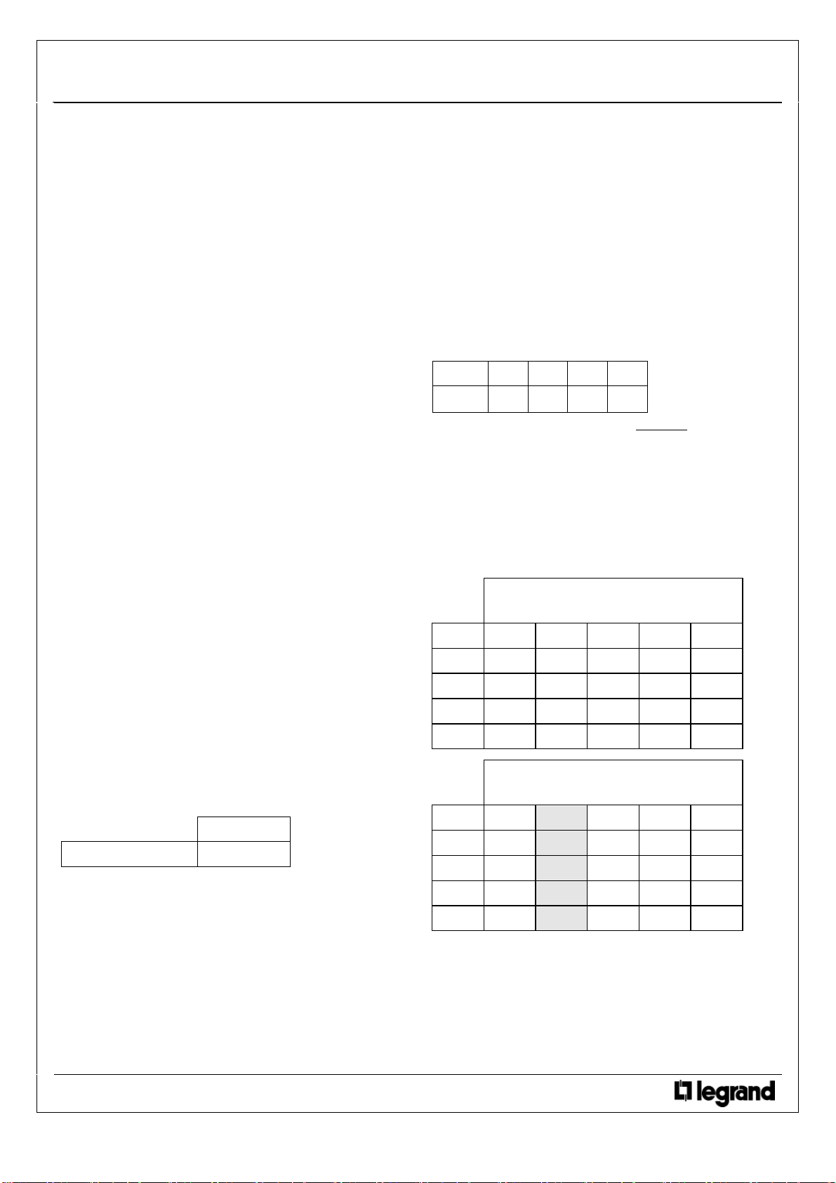
Dissipated power (W):
. For the 2P isolating switch
In 16 A 25 A 32 A 63 A
2P 1,5 2,4 3,1 5,5
. Impedance of the isolating switch (Ω) = P dissipée
2
In
Derating of the isolating switch in terms of ambient
temperature :
. Reference temperature : 40 °C in accordance with EN/IEC 60947-3
standard.
. Rated characteristics of the isolator switch may be modified
depending on the ambient temperature inside the enclosure where it
is installed.
Endurance:
. 20000 operations without load.
. 2000 operations at In and Un.
Enclosure material:
. Polyester.
. Characteristics of this material: self extinguishing, heat and fire
resistant according to EN 60898-1, glow-wire test at 960°C for
external parts made of insulating material necessary to retain in
position current-carrying parts and parts of protective circuit (650°C
for all other external parts made of insulating material).
Weight of the isolating switch:
. 0,581 kg.
Volume and packaging:
Volume (dm3)
Double pole 1,2 dm
3
Ambient temperatures:
. Operation: from - 25℃ to + 70℃
. Storage: from - 40℃ to + 70℃
Degree or class of protection:
. Protection index of terminals against solid and liquid bodies:
IP 20 (in according with standards IEC 529, EN 60529 and NF C
20-010).
. Protection index of the box against solid and liquid bodies:
IP 40 (in according with standards IEC 529, EN 60529 and NF C
20-010).
. Protection index against mechanical shocks: IK 02 (in according
with standards EN 50102 et NF C 20-015).
Ambient temperature in °C
Current in Amps
In (A) - 25°C - 10°C 0°C 10°C 20°C
16 21,9 20,0 18,7 18,0 17,3
25 34,5 31,5 29,5 28,3 27,2
32 45,8 41,0 37,8 36,5 34,9
63 88,1 80,6 75,6 72,5 69,9
Ambient temperature in °C
Current in Amps
In (A) 30°C 40°C 50°C 60°C 70°C
16 16,6 16,0 15,4 14,7 14,1
25 26,0 25,0 24,0 22,7 21,7
32 33,3 32,0 30,7 20,1 27,8
63 66,1 63,0 59,8 56,1 52,9
: F01282EN/02 Updated : 24/08/2016 created : 7/10/2011
3 / 4
Page 4
Isolating switch DX ≤ 63 A
Te
direct current, 800V
6. COMPLIANCE AND APPROVALS
In accordance with standards:
. EN/IEC 60947-2
. EN/IEC 60947-3.
. European directives : 73/23/CEE + 93/68/CEE.
. These isolating switches can be used in the conditions of use
defined by IEC/EN 60947 standard.
. The isolating switch performances may be modified in case of
particular climatic conditions.
Plastic materials :
. Halogens-free plastic materials.
. Marking of parts according to ISO 11469 and ISO 1043.
Packaging:
. Design and manufacture of packaging in accordance with Decree
98-638 of 07.20.98 and Directive 94/62/EC
7. AUXILIARIES AND ACCESSORIES
Wiring accessories:
. Sealable screw cover (Cat. No. 4 063 04).
. Insulation shields (Cat. No. 4 063 05).
Cat. n°(s) : 4 142 21 / 23 / 24 / 26
Signalling auxiliaries:
. Auxiliary changeover switch (½ module – Cat. No. 4 062 58).
. Fault signalling changeover switch (½ module – Cat. No. 4 062
60).
. Auxiliary changeover switch which can be modified into fault
signalling changeover switch (½ module – Cat. No. 4 062 62).
. Auxiliary changeover switch + fault signalling changeover switch
which can be modified into two auxiliary changeover switches (1
module – Cat. No. 4 062 66).
Control auxiliaries:
. It is imperative not to associate control auxiliaries with the
isolating switch .
Auxiliaries and isolating switches combinations allowed :
. Auxiliaries must be fitted on the left side of the isolating switch.
. Maximum of 2 auxiliaries per isolating switch whose only one halfmodule wide auxiliary.
Installation software :
. XL PRO
3
chnical data sheet : F01282EN/02 Updated : 24/08/2016 created : 7/10/2011
4 / 4
 Loading...