

Page 1
1. Introduction
OnQ Amplified Combo Modules provide a structured method for distributing
telephone service and RF (cable TV) off air signals throughout a residence.
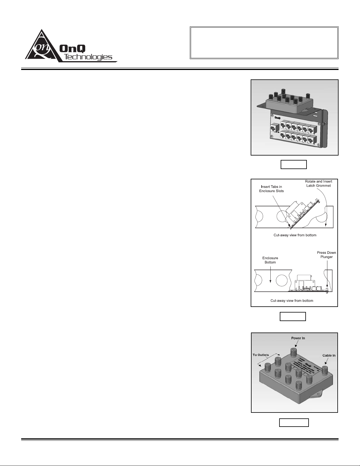
OnQ Amplified Combo Modules can be mounted in OnQ Service Center
Enclosures and come in several different telecom combinations; an example
(12+8) is shown in Figure 1 to the right.
2. Description
The “video” portion of the module has vertical access “F” style fittings for
connecting incoming and outgoing cables, as well as power.
NOTE: The Video module is a 5-1000 MHz amplifier with typically 4.0 dB
of gain per output port and an insertion loss of typically -1.0 dB in the
5-42 MHz range.
The “telecom” portion provides an RJ45 modular jack or 110 punchdown
block for connecting and distributing incoming telephone service to room
locations. Also provided on some configurations is a modular jack labeled
“Security” for interfacing to security systems.
NOTE: The OnQ Combo Module has a vertical dimension of 5 inches.
A total of 7 inches of enclosure space is required for coax cabling.
3. Installation
A. Mounting in Enclosure (refer to Figure 2).
1) Align tabs on the module with slots on rail enclosure.
2) Insert tabs by angling module away from the back of the
enclosure.
3) Rotate the module and insert fasteners on module into
corresponding holes on rail of enclosure. (Plunger must be in
a pulled position for fastener to engage hole.).
4) Push plunger in to lock module in place. Pull on module to
ensure module is locked properly in place.
B. Service Connection - Video Portion (refer to Figure 3).
1) Identify incoming service cable(s) and route to “Cable In” fitting(s) on module.
2) Attach an RG-6 “F” connector to the cable. Connect to fitting
on module and finger-tighten.
C. Service Connection - Telecom Portion
1) Identify incoming service cable and route to RJ45 jack or 110
punchdown block labeled “Line In”.
2) Trim the cable to allow at least three (3) inches of excess
cable.
3) Terminate the cable with an EZ-RJ45 modular plug
(P/N 364554-01, not included) if applicable. Be sure to use
proper terminating tool (P/N 364555-01 per IS-0177). If using
110 punchdown block, insert leads and terminate using
punchdown tool (P/N 363293-01, not included).
OnQ Technologies, Inc.
P.O. Box 60907
Harrisburg, PA 17106-0907
800-321-2343
www.onqtech.com
Installation/Instruction Sheet
OnQ Amplified Combo Module
IS-0266 Rev. O
IS-0266 Rev. O Page 1 of 2
Figure 2
Figure 3
Figure 1
Page 2
D. Terminating the Outlet Cables
1) Route the cable to the RJ45 Jack or 110 punchdown block on the module.
2) Trim the cable to allow at least three (3) inches of excess cable.
3) Terminate the cables as outlined above.
4) Insert RJ45 Plugs into appropriate jacks (if applicable).
E. Terminate and Connect Video Cables (refer to Figure 3).
1) Locate video source cable (CATV or antenna) position to attach to the input of the splitter.
2) Cut the cable approximately two (2) inches beyond the splitter, allowing slack for cable
management. Use a high quality cable cutter to avoid distortion of the cable and center
conductor. If cable marking is cut off, re-mark in an area that will be visible after installation.
3) Strip and prep per connector instructions. Use a coax stripper to ensure clean cuts without
damaging the center conductor.
4) Install high quality “F” style connectors. Use proper insertion and crimp tools.
5) Attach securely to the proper port of the splitter.
6) Repeat for outlet cables.
F. Securing Cables
After all cables are connected to the module, the cables should be bundled and grouped to allow ease
of maintenance. Wire management straps (P/N 363491-01), may be used to bundle cable.
G. Making a Power Cable Jumper
1) The “video” portion of this combo module is powered by a typical power cube that plugs into the
AC outlet at the bottom of the enclosure.
2 ) The actual power cable that goes between the power cube and the video module must be con-
structed by terminating an appropriate length of RG-6 (solid copper) with male “F” connectors.
3) Once terminated, screw one “F” connector onto the video module’s “power in” jack, and screw
the other end of the power cable onto the “F” connector jack on the power cube.
4. Other Applications (If Applicable)
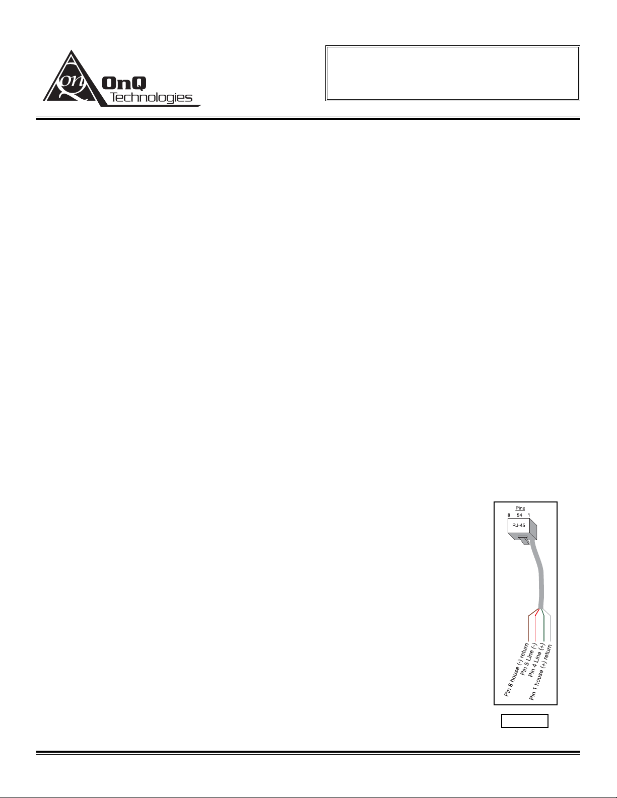
A. Security Interface (refer to Figure 4 for Pin Out)
1) To enable line seizure and dial out capability to most security systems,
connect the RJ31X cable (supplied with the security system) to the RJ45
“Security” jack on the module. TURN OFF SW1 to activate security link.
Connect the other end to the security system as outlined in the security
system installation instructions.
2) To disable security, remove plug from “security” jack and set SW1 to
“ON”.
OnQ Technologies, Inc.
P.O. Box 60907
Harrisburg, PA 17106-0907
800-321-2343
www.onqtech.com
Installation/Instruction Sheet
OnQ Amplified Combo Module
IS-0266 Rev. O
IS-0266 Rev. O Page 2 of 2
Figure 4
 Loading...