

Page 1
INSTRUCTION/INSTALLATION SHEET
Combo Modules (B Series)
301 Fulling Mill Road, Suite G
Middletown, PA 17057
Phone (800) 321-2343 / Fax (717) 702-2546
www.onqlegrand.com
1. Introduction
The On-Q/Legrand Combo Modules provide a structured method for
distributing telephone service and RF (CATV) off air signals throughout a
residence. On-Q Combo Modules can be mounted directly in any On-Q
style enclosures and come in several different telecom/video
combinations; an example (6+8) is shown in Figure 1.
2. Description
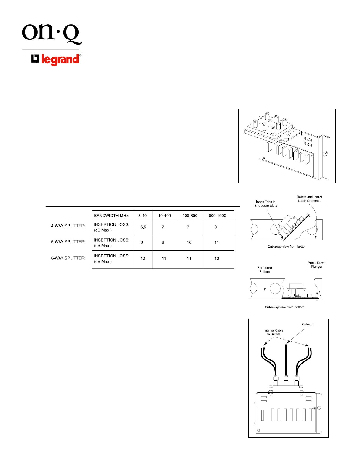
The “video” portion of the Combo Module has vertical access “F” style
fittings for connecting the coaxial cables.
NOTE: Table 1 shows the insertion loss associated with each
version of the video portion of our Combo Modules.
3. Installation
Page 1 of 2
©Copyright 2008 by On-Q/Legrand All Rights Reserved.
Table 1
The “telecom” portion of the Combo Module also comes in several
versions, each with 110-style punch down connections for up to 4
incoming lines and extensions. Some versions also have an RJ-31X
security interface jack.
NOTE: While the Combo Module has a vertical height of 5 inches, a
total of 7 vertical inches is required because of the coaxial cable
connections.
A. Mounting in On-Q Enclosure (see Figure 3):
1) Align tabs on the module with slots in the enclosure.
2) Insert tabs by angling module away from the back of the enclosure.
3) Rotate the module and insert fasteners on module into
corresponding holes in the enclosure. (Plunger must be in a pulled
position for fastener to engage hole).
4) Push plunger in to lock module in place. Pull on module to ensure it
is locked properly in place.
B. Service Connection – Video Portion (see Figure 3):
1) Route incoming service cable to “Cable In” fitting on module.
2) Attach an RG-6 “F” connector to the cable and connect to a fitting on
the module and finger tighten.
C. Outlet Drop Connections:
1) Route outlet cables to appropriate fittings on module.
IS-0162 REV. A
Figure 1
Figure 2
Figure 3
Page 2
INSTRUCTION/INSTALLATION SHEET
Combo Modules (B Series)
301 Fulling Mill Road, Suite G
Middletown, PA 17057
Phone (800) 321-2343 / Fax (717) 702-2546
www.onqlegrand.com
2) Attach an RG-6 “F” connector to each cable and connect to a fitting
on the module and finger tighten.
NOTE: Do not bend cable in less than a 2 inch radius.
NOTE: Cables should all be labeled. Record room locations for cables
to the outlets.
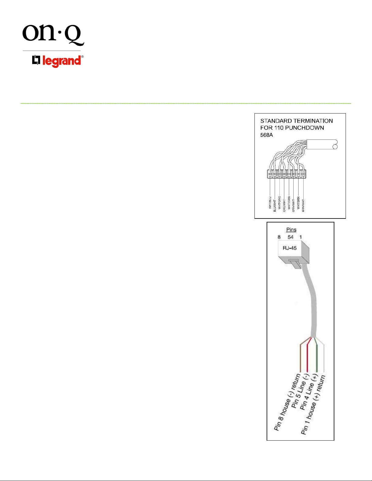
D. Incoming Telecom Service Cable Installation (see Figure 4):
1) Route incoming service cable to “Line In” 110 punch down strip on
module. Allow slack for bundling and trim cable 2 inches beyond
punch down strip.
2) Strip off approximately 4 inches of the outer jacket and position the
pairs over the color coded slots on the 110 strip (see Figure 4).
NOTE: Do not untwist pairs. White wires may not have color trace
stripe. Keep white wire paired with appropriate colored wire.
3) Punch down and trim wires using a punch down tool and remove any
excess wire.
4) Tug lightly on the cable to insure wire is securely fastened.
E. Outlet Telecom Cable Termination:
1) Route outlet telecom cables to appropriate numbered 110 punch
down strips on module. Allow slack for bundling and trim cables 2
inches beyond punch down strip.
2) Strip off approximately 4 inches of the outer jacket and position the
pairs over the color coded slots on the 110 strip (see Figure 4).
NOTE: Do not untwist pairs. White wires may not have color trace
stripe. Keep white wire paired with appropriate colored wire.
3) Punch down and trim wires using a punch down tool and remove any
excess wire.
4) Tug lightly on the cable to insure wire is securely fastened.
5) Record room names/numbers and connection numbers on wire
layout label inside enclosure.
F. Securing Cables:
1) After all cables are connected to the module, the cables should be
bundled with wire management straps and grouped to allow ease of
maintenance.
4. Other Applications (If Applicable)
A. Security Interface (see Figure 5):
1) To enable line seizure and dial out capability to most security
systems, connect the RJ-31X cable (supplied with the security
system) to the RJ-45 “Security” jack on the module. TURN OFF Line
1 to activate the security link. Connect the other end to the security
system as outlined in the security system installation instructions.
2) To disable security, remove the connector from the “Security” jack
and set Line 1 to “ON”.
IS-0162 REV. A
Figure 4
Figure 5
Page 2 of 2
©Copyright 2008 by On-Q/Legrand All Rights Reserved.
 Loading...