

Page 1
128, av. du Maréchal-de-Lattre-de-Tassigny - 87045 LIMOGES Cedex
Tel: +33 (0)5 55 06 87 87 Fax: +33 (0)5 55 06 88 88
www.legrand.com
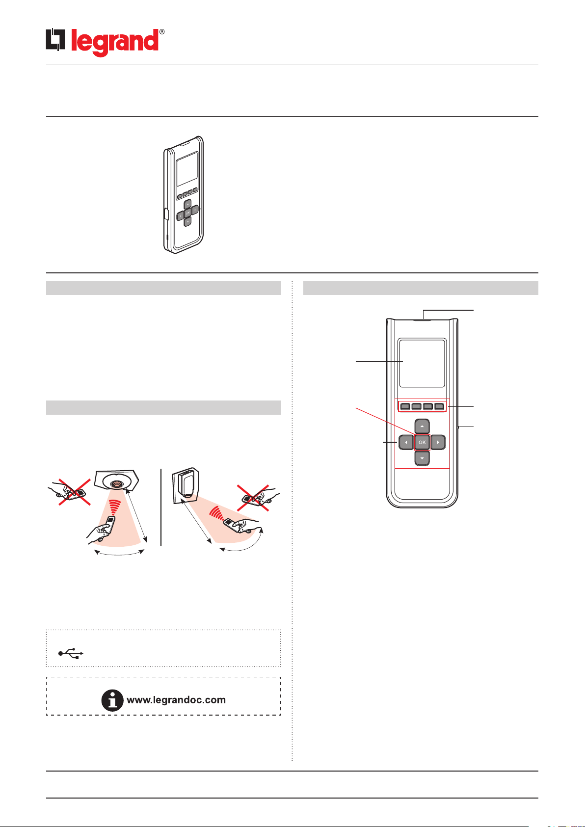
Configuration tool with screen
Using this infrared configuration tool the user can, without touching the
device:
- set the parameters of SCS and KNX self-contained sensors, dynamic
light strips and SARLAM bulkhead lights (time delay, daylight setpoint,
detection sensitivity, etc.)
- adjust, correct, debug the system according to the characteristics of the
installation location and customer requirements
- save the settings (maximum of up to 26 configuration files)
- duplicate onto other sensors (copy/paste a typical setting)
Catalogue number(s): 0 882 30
CONTENTS Page
1. Use......................................1
2. Technical characteristics...............1
3. Navigation..............................2
4. Updating ...............................5
5. Standard EN12464-1
recommendations .....................7
6. Care.....................................8
7. Standards ..............................8
2. TECHNICAL CHARACTERISTICS CONTINUED1.USE
IR transmission
and reception LED
Display screen
2. TECHNICAL CHARACTERISTICS
Infrared communication technology (4 m max.)
In the direction of the product to be measured
At a maximum angle of +/-15° in the axis of the IR transmission and
reception LED (see figure)
4 m
+/- 15°
Backlit screen (automatic switch-off)
Weight: 71 g
Impact resistance: IK04
Operating temperature: -5°C to +45°C
Storage temperature: -20°C to +70°C
Recharging: Use a mini USB cable (not supplied) to recharge the
conguration tool via a standard USB socket.
Note: Updating software is available on our website
4 m
+/- 15°
On/Off and OK
Control and navigation
keys
Works with all factory pre-set compatible sensors (infrared, ultrasound
or dual technology) with dynamic light strips and SARLAM bulkhead
lights.
After fully interrogating the device, only the parameters concerning this
device appear.
Function access
keys
Mini-USB
connector
Technical data sheet: F01163EN/01 Updated: 30/03/2015 Created: 07/07/2010
1/8
Page 2
Configuration tool with screen
3. NAVIGATION 3. NAVIGATION CONTINUED
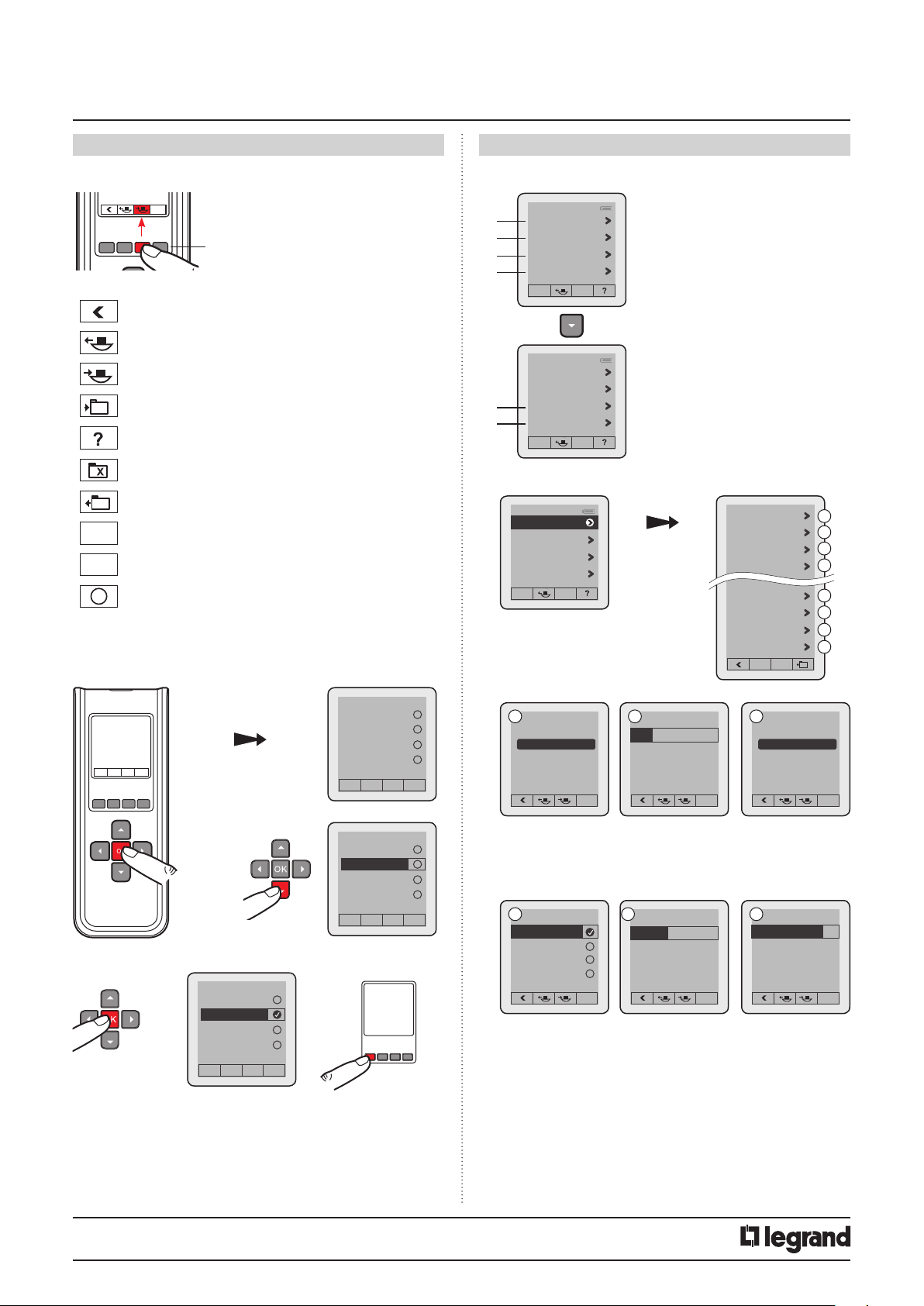
3.1 Pictograms 3.2.2 Parameter selection
Catalogue number(s): 0 882 30
The 4 buttons control the pictogram functions
displayed above
Back to previous page
Takes the current sensor configuration
Sends a configuration to the sensor
Creates a backup file
Provides the website address for the online technical
documents (www.legrandoc.com)
Deletes a file
Displays a file's parameters
del
Deletes a product from the configuration
learn
Adds a product to the configuration
i
Information
3.2 Instructions for use
3.2.1 Language selection
1
2
3
4
5
6
1
Sensor parameters
Advanced mode
Files
Sensor PnL
Files
Sensor PnL
Test
Settings
Sensor parameters
Sensor parameter
Advanced mode
Files
Sensor PnL
Time delay
Sensitivity
Daylight setpoint
Mode
Detection scheme
Alert
Standby level
Standby time
A
B
C
D
E
F
G
H
3
ON
2-3 s
Français
English
English
Italiano
Español
1
2
Français
English
Italiano
Español
Français
English
English
Italiano
Español
x 2
A
Time delay
000 H 15 Min 00 Sec
Max. time delay
255 H 59 Min 59 Sec
D
Mode
Auto on/off
Walkthrough
Manual on / Auto off
Partial on / Group of f
B
Sensitivity
PIR
Very high < >
US High < >
HF High < >
Very high
High
Medium
Low
E
Detection scheme
Initial
IR and US < >
Maintain IR or US < >
Retrigger IR or US < >
IR and US
IR or US
HF only
PIR and HF
PIR or HF
IR only
US only
C
Daylight setpoint
0500 lux
Max: 1275 lux
F
Alert
Audible
ON/OFF
Status change "BEEP"
on the sensor
Technical data sheet: F01163EN/01 Updated: 30/03/2015 Created: 07/07/2010
2/8
Page 3
Configuration tool with screen
3. NAVIGATION CONTINUED 3. NAVIGATION CONTINUED
Catalogue number(s): 0 882 30
G
Standby level
Max: 100%
A
Time delay
10%
H
Standby time
No standby
Max: unlimited
Length of time the load is on after detection. See technical data sheet
for the associated sensor.
B
Sensitivity
Sets the sensor range (see technical data sheet for the associated
sensor).
C
Daylight setpoint
Value at which the load switches on if the light level is less than the
setting and goes off if it is above this setpoint. The daylight setpoint
can be set up to a maximum of 1275 lux.
D
Mode
There are 4 different operating modes.
Auto on/Auto off mode:
Comes on automatically:
- On detection of a presence if there is insufficient natural light.
Turns off automatically:
- If no presence is detected and at the end of the time delay set.
- Or if there is sufficient natural light (regulation function activated).
Any new detection triggers an automatic switch-on if there is
insufficient light.
Walk-through:
- If no presence is detected in the 3 minutes following an initial
detection, the sensor will cut off the load after 3 minutes.
- If another movement is detected in the 3 minutes following initial
detection, the device will cut off the load at the end of the set time
delay.
Manual on/Auto off mode:
The lighting is switched on manually and switched off automatically:
- If no movement is detected at the end of the set time delay.
After switch-off, if another movement is detected within a 30-second
period, the lighting switches on automatically.
After 30 seconds, the lighting has to be switched on manually.
Partial on/Group off mode:
This mode is used to ungroup circuits that are switched on upon
detection and circuits that will be switched off at the end of detection.
Example: Upon detection I switch on the main lighting and I can
control backup lighting manually in parallel. At the end of detection,
the sensor controls switching off the main lighting and the backup
lighting circuits.
E
Detection scheme
This menu concerns the detection technologies. There are several
possible types of combination.
IR and US: The sensor needs both technologies in order to switch on
the load.
IR or US: The sensor needs one of these technologies in order to switch
on the load.
HF only: The sensor needs HF technology in order to switch on the load.
IR only: The sensor needs IR technology in order to switch on the load.
US only: The sensor needs US technology in order to switch on the
load.
F
Alert
A "BEEP" is transmitted before the end of the time delay programmed.
G
Standby level
Warns of switch-off by lowering the light level before switch-off.
H
Standby time
Used to adjust the switch-off warning duration.
NB: Choosing an unlimited duration allows there to be a minimum light
level when no presence is detected.
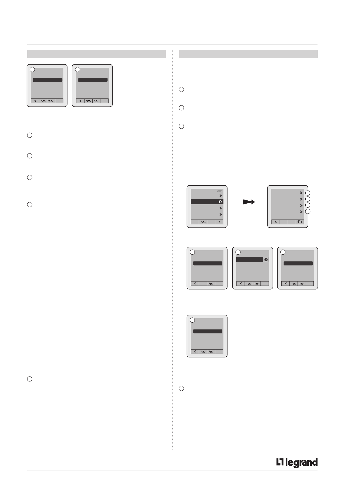
3.2.3 Advanced mode
Sensor parameter
2
Advanced mode
Advanced mode
Files
Sensor PnL
A
Max. lux: 99,995
D
Closed loop
Open loop
A
Calibration
Calibration
0000 lux
Loop type
Closed loop
B
Light regulation
Light regulation
Calibration
Light regulation
Provision of light
Loop type
C
Provision of light
Max. lux: 1275
A
B
C
D
Auto
In order to calibrate the sensor, the surrounding light level must first
be measured using a luxmeter. The measured surrounding light level
should then be transmitted to the sensor.
Steps for setting the electric light factor:
- Put the light on and close the shutters
- Wait 2 minutes
- Measure the light level below the cell using a luxmeter
Enter this value in the tool and send it to the cell. This calibration will be
acknowledged during the next detection cycle.
Technical data sheet: F01163EN/01 Updated: 30/03/2015 Created: 07/07/2010
SOMMAIRE
3/8
Page 4

Configuration tool with screen
3. NAVIGATION CONTINUED 3. NAVIGATION CONTINUED
Catalogue number(s): 0 882 30
B
Light regulation
Principle: Light regulation distinguishes between the available natural
light and the provision of artificial light.
It continuously measures the natural light level (daylight) and
compensates for the lack of this natural light level by switching on the
artificial light.
The light level cell distinguishes between the available natural light and
that provided by artificial light and, by comparing with the daylight
setpoint, the product adjusts the provision of artificial light.
The daylight setpoint set in the products is a threshold below which
the area being lit must not fall, as indicated in standard NF 12464-1.
C
Provision of light
This is the quantity of additional lux contributed by switching on the
artificial light.
D
Loop type
There should be outside light available for correct operation of the
regulation function.
Closed loop:
The sensor measures the light level in its coverage area and regulates
the lighting according to this measurement.
Open loop:
The sensor does not measure the light level in its coverage area.
The lighting is regulated according to the available outside light.
3.2.4 Files
Files
File name
3
Sensor parameter
Advanced mode
Files
Files
Sensor PnL
Example
xx H xx MIN xx Sec
PIR > High
US > Low
Closed loop
xxx Lux
x Lux
Light regulation
Mode
Detection scheme
Detection scheme
Detection scheme
Alert
The "Files" menu can be used to display the customised settings saved.
Up to 26 files can be saved.
Time delay
Sensitivity
Sensitivity
Loop type
Daylight setpoint
Provision of light
Enabled/Disabled
Walkthrough
Initial > IR only
Maintain > IR only
Retrigger > IR only
Enabled/Disabled
3.2.5 Sensor PnL
Sensor PnL
Group PnL
Add peripheral
A
End
Learn
OK
Learn
Del
A
+
-
4
Sensor parameter
Advanced mode
Files
Sensor PnL
Sensor PnL
Adds a channel
to the group
Deletes a channel
from the group
Ends the procedure Goes to
the next
channel
PnL = Push & Learn
Teach mode allowing several products to be combined in a system.
The configuration tool allows this function to be used remotely.
3.2.6 Test
Walk test
End time delay
Initial state
ON
OFF
5
Files
Sensor PnL
Test
Test
Settings
Walk test
Mode used to check how the installation is operating.
When the command is sent, the sensor goes into test mode for
5 minutes. The sensor is therefore in Auto ON/Auto OFF mode and the
time delay is set at 5 sec.
End time delay
Used to force the end of the current time delay.
Initial state
Used to exit Test mode and puts the installation into operating mode
(initial state).
This function does not modify the selected parameters.
ON
Used to force switch-on.
OFF
Used to force switch-off.
Technical data sheet: F01163EN/01 Updated: 30/03/2015 Created: 07/07/2010
4/8
Page 5

Configuration tool with screen
3. NAVIGATION CONTINUED 4. UPDATING CONTINUED
Catalogue number(s): 0 882 30
3.2.7 Settings
Files
Sensor PnL
Test
Settings
Tool config
6
A
Français
English
Italiano
Español
Languages
B
Version
Firmware : X.X.XX
4. UPDATING
4.1 Installing the software
1 Connect to the website www.legrandoc.com
Languages
Version
Battery
C
4 Download the file
A
B
C
Battery level
5 Install the updating file
6 Click on Yes
7 Click on Yes
2 Enter product catalogue number 0 882 30
then click OK
The page concerning the available product documentation is displayed
3 Click on the icon to access software downloading
8 Select the desired language then click OK
9 Click on Next
Technical data sheet: F01163EN/01 Updated: 30/03/2015 Created: 07/07/2010
SOMMAIRE
5/8
Page 6

Configuration tool with screen
4. UPDATING CONTINUED 4. UPDATING CONTINUED
Catalogue number(s): 0 882 30
Click on Next after accepting the licence contract terms
10
Click on Browse to indicate the destination directory
11
Click on Next
12
This window is used to display the progress of the software installation
Select "Install this driver software anyway"
15
Installation is complete
Click on Finish
16
To create a software icon on your desktop, check the corresponding
13
box, then click on Next
This window summarises the tasks selected earlier
Click on Install to confirm these actions, or else on Previous to
14
amend these tasks
4.2 Launching the software
1 Launch the application shortcut on the Desktop
Technical data sheet: F01163EN/01 Updated: 30/03/2015 Created: 07/07/2010
6/8
Page 7

Configuration tool with screen
4. UPDATING CONTINUED 4. UPDATING CONTINUED
Catalogue number(s): 0 882 30
2 Select the application
3 Eg: Lighting management
4 Connect the configuration tool to the PC
Alert window warning that some data may be lost. Select Continue to
start updating.
Updating is complete.
Note: All technical information is available on
Important: The conguration tool must be switched o
5 Choose whether or not to start updating
Once connected, the configuration tool should switch on. If not,
disconnect and then reconnect it to the USB cable.
5. STANDARD EN124641 RECOMMENDATIONS
Commercial premises - office buildings:
Passage areas and corridors: 100 lux
Stairs: 150 lux
Canteens: 200 lux
First-aid room: 500 lux
Warehouse: 100 lux
Offices: 300 - 500 lux
Conference rooms: 500 lux
Reception rooms: 300 lux
Technical drawing: 750 lux
Manufacturing areas:
Packaging rooms: 300 lux
Visual work during manufacturing: 1000 lux
Assembly line: 1500 lux
Warehouses:
Sales areas: 300 lux
Checkout areas: 500 lux
Other examples:
Moonlit night: 0.5 lux
Well-lit street at night: 20 - 70 lux
Living premises: 100 - 200 lux
Well-lit apartment: 200 - 400 lux
Work premises: 200 - 3000 lux
Stadium at night: 1500 lux
Outside with cloudy sky: 25,000 lux
Outside in full sunshine: 50,000 to 100,000 lux
Technical data sheet: F01163EN/01 Updated: 30/03/2015 Created: 07/07/2010
SOMMAIRE
7/8
Page 8

Configuration tool with screen
6. CARE
Do not use: acetone, tar-removing cleaning agents or trichloroethylene.
Resistant to the following products: - Hexane (En 60669-1)
- Methylated spirit
- Soapy water
- Diluted ammonia
- Bleach diluted to 10%
- Window-cleaning products
WARNING: Always test before using other special cleaning
products.
7. STANDARDS
Directive: CE
Product standard: EN 60 669-2-1
Environmental standards:
- European Directive 2002/96/EC:
WEEE (Waste Electrical and Electronic Equipment)
- European Directive 2002/95/EC:
RoHS (Restriction of Hazardous Substances)
Catalogue number(s): 0 882 30
Technical data sheet: F01163EN/01 Updated: 30/03/2015 Created: 07/07/2010
8/8
 Loading...