

Page 1

Lighting management sensor - PIR
Cat. No(s): 0 489 14
CONTENTS Page
1. Use . . . . . . . . . . . . . . . . . . . . . . . . . . . . . . . . . . . . .1
2. Technical characteristics. . . . . . . . . . . . . . . . .1
3. Dimensions. . . . . . . . . . . . . . . . . . . . . . . . . . . . .2
4. Connection . . . . . . . . . . . . . . . . . . . . . . . . . . .2
5. Removal . . . . . . . . . . . . . . . . . . . . . . . . . . . . . . . .3
6. Installation . . . . . . . . . . . . . . . . . . . . . . . . . . . . .3
7. Operation . . . . . . . . . . . . . . . . . . . . . . . . . . . . . .5
8. Settings . . . . . . . . . . . . . . . . . . . . . . . . . . . . . . . .6
9. Performance. . . . . . . . . . . . . . . . . . . . . . . . . . . .7
10. Care . . . . . . . . . . . . . . . . . . . . . . . . . . . . . . . . . . . .8
11. Standards and certifications . . . . . . . . . . . . .8
12. Troubleshooting . . . . . . . . . . . . . . . . . . . . . . . .8
1. USE
This device allows a light source to be controlled automatically by
detecting movement in a monitored area.
It can be installed in work areas (offices, classrooms, meeting rooms,
open-plan offices).
Motion sensor with 180° detection angle.
Detection type: infrared (PIR)
Mounting type: wall
2. TECHNICAL CHARACTERISTICS
Voltage: 240 V~
Frequency: 50/60 Hz
No-load power consumption: 0.6 W
Output via normally open contact connected to the phase
Wiring: 2 x 2.5 mm
Number of terminals: 4
Terminal type: screw
Stripping length: 8 mm
Drilling diameter: 67 mm with flush-mounting box
Weight: 114 g
Impact resistance: IK04
Penetration by solid and liquid matter: IP42
Usage temperature: - 5°C to + 45°C
Storage temperature: - 20°C to + 70°C
1 2 3 4 5 6 7 8
2
2. TECHNICAL CHARACTERISTICS (continued)
Products approved for 40,000 operations
Mains zero breaking: in order to limit the effect of induced currents on
cut-off relays by fluorescent loads in particular, this sensor breaks the
voltage at mains zero. Switching occurs when the voltage is at point 0
which ensures a longer life for sources and for the sensor.
Cover removed
Learn LED
Learn button
Light level cell
Sensor/PIR sensor
Detection LED
230 V~ 2000 W
110 V~ 1000 W 500 VA 500 VA 5x(2x36 W) 125 W 125 W 125 W 250 VA
8.5 A
1000 VA
4.3 A
1000 VA
4.3 A
10x(2x36 W)
4.3 A
250 W
1 A
250 W
1 A
250 W
1 A
500 VA
2.1 A
1 - Halogen bulbs
2 - ELV halogen, compact fluorescent and fluorescent bulbs with
8 - Contactor
9 - Motor
separate electronic ballast
3 - ELV halogen, compact fluorescent and fluorescent bulbs with
separate ferromagnetic ballast
4 - Fluorescent tubes
5 - Compact fluorescent bulbs with built-in electronic ballast
6 - Compact fluorescent bulbs with built-in ferromagnetic ballast
7 - LED bulbs
230 V~ 500 VA
110 V~ 250 VA
U ≤ 30 V=
2.1 A max.
2.1 A
max.
I max. ≤ 2.1 A
Technical data sheet: S000077897EN-1 Updated: Created: 10/03/2014
1/8
Page 2

Lighting management sensor - PIR
3. DIMENSIONS
With protective cover
84 46
Cat. No(s): 0 489 14
31 118
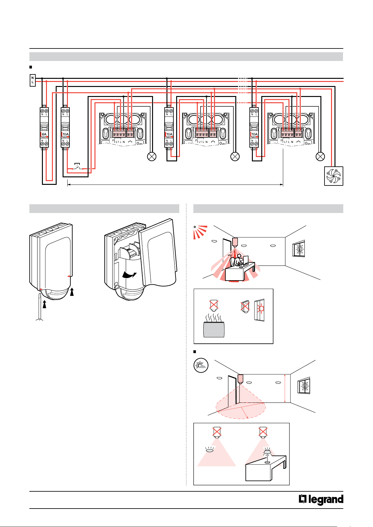
4. CONNECTION
4.1 Wiring with auxiliary control:
PB
100 m max.
4.3 Wiring for a single load connected in parallel
8.5 A
max.
2.1 A max.
4.2 Wiring without auxiliary control:
=
V
U ≤ 30 V=
8.5 A
max.
2.1 A max.
SNS2S1
PB
100 m max.
Technical data sheet: S000077897EN-1 Updated: Created: 10/03/2014
CONTENTS
L
8.5 A
max.
2.1 A max.
2/8
Page 3
Lighting management sensor - PIR
4. CONNECTION (continued)
4.4 Wiring for several loads connected in parallel
PB
8.5 A
max.
100 m max.
8.5 A
max.
Cat. No(s): 0 489 14
SNS2S1
LNL2L1
8.5 A
max.
2.1 A max.
5. REMOVAL 6. INSTALLATION
6.1 Sensor positioning
2
PIR
1
6.2 Recommended light exposure
2.5 m
3.5 m
Technical data sheet: S000077897EN-1 Updated: Created: 10/03/2014
CONTENTS
3/8
Page 4

Lighting management sensor - PIR
Cat. No(s): 0 489 14
6. INSTALLATION (continued)
6.3 Fitting
1
60 mm
6. INSTALLATION (continued)
6.3 Fitting (continued)
0 489 71
4
6.4 Choice of detection zone
1
2
60 mm
CLICK
SNAP
50
Ø > 67
3
2 3
CLICK
Technical data sheet: S000077897EN-1 Updated: Created: 10/03/2014
CONTENTS
4/8
Page 5

Lighting management sensor - PIR
Cat. No(s): 0 489 14
7. OPERATION
Manual ON/Auto OFF mode:
Pressing the auxiliary control allows the load to be switched on or off
manually. If the control is not pressed, the sensor will cut off the load
at the end of the time delay or when the light level threshold has been
reached.
Auto ON/OFF mode:
The load will be switched on and off automatically.
Option: It is possible to manage the sensor using infrared remote
control: Cat. Nos. 0 882 20/31.
7.1 More than one sensor and more than one load
The products can be synchronised in two steps:
- one long press (>1s) all the sensors (S) switch to the ON state
- one short press all the sensors (S) inversion of OFF to ON or ON to OFF
L1 OFF
L2 OFF
Ln OFF
L1 ON
L2 ON
Ln ON
S1 OFF
S2 OFF
Sn OFF
S1 ON
S2 ON
Sn ON
PB
PB
< 1 s
< 1 s
L1 ON
L2 ON
Ln ON
L1 OFF
L2 OFF
Ln OFF
S1 ON
S2 ON
Sn ON
S1 OFF
S2 OFF
Sn OFF
7. OPERATION (continued)
7.2 Several sensors connected to a single load
L OFF
L ON
L ON
L ON
S1 OFF
S2 OFF
Sn OFF
S1 ON
S2 ON
Sn ON
S1 ON
S2 OFF
Sn OFF
S1 ON
S2 OFF
Sn OFF
PB
< 1 s
PB
< 1 s
PB
< 1 s
PB
> 1 s
+
< 1 s
L ON
L OFF
L ON
L OFF
S1 ON
S2 ON
Sn ON
S1 OFF
S2 OFF
Sn OFF
S1 OFF
S2 ON
Sn ON
S1 OFF
S2 OFF
Sn OFF
L1 ON
L2 OFF
Ln OFF
L1 ON
L2 OFF
Ln OFF
L1 ON
L2 OFF
Ln OFF
S1 ON
S2 OFF
Sn OFF
S1 ON
S2 OFF
Sn OFF
S1 ON
S2 OFF
Sn OFF
PB
< 1 s
PB
> 1 s
+
< 1 s
PB
> 1 s
L1 OFF
L2 ON
Ln ON
L1 OFF
L2 OFF
Ln OFF
L1 ON
L2 ON
Ln ON
S1 OFF
S2 ON
Sn ON
S1 OFF
S2 OFF
Sn OFF
S1 ON
S2 ON
Sn ON
L ON
S1 ON
S2 OFF
Sn OFF
PB
> 1 s
L ON
S1 ON
S2 ON
Sn ON
Technical data sheet: S000077897EN-1 Updated: Created: 10/03/2014
CONTENTS
5/8
Page 6

Lighting management sensor - PIR
Cat. No(s): 0 489 14
8. SETTINGS
8.1 Detection parameters
Sensor parameter Default
Time delay 15 min
Sensitivity
Auto on/Auto off Inactive
Walk-through
mode
Modes
Manual on/Auto
off
Initial PIR Not modifiable −
Maintain PIR Not modifiable
system
Detection
Restart
Alarm Inactive
value
PIR (very
high)
Active
Inactive
Time delay: Length of time the load is on after detection occurs.
Sensitivity: Detection range setting.
Modes:
Auto on/Auto off mode:
Comes on automatically:
- At the detection of a presence if there is an insufficient natural level of
light.
Turns off automatically:
- If no presence is detected and at the end of the time delay set.
- Or if the natural light level is sufficient (regulation activated).
Any new detection triggers an automatic switch-on if there is
insufficient light.
Walk-through mode:
- If no presence is detected in the 20 seconds following an initial
detection, the product will cut off the load after 3 minutes.
- If another presence is detected in the 3 minutes following initial
detection, the device will cut off the load at the end of the set time
delay.
Manual on/Auto off mode:
Manual switch-on, automatic switch-off:
- When no presence is detected and at the end of the set time delay.
After switch-off, any new detection within a 30-second period triggers
an automatic switch-on. The Restart function must be activated.
After 30 seconds the device is switched on via a manual control.
Modifiable
parameters
3, 5, 10, 15, 20 min −
0 - 59 min 59 s −
Low, medium,
high, very high
Activate/
Deactivate
Activate/
Deactivate
Activate/
Deactivate
PIR and/or US, PIR,
PIR
US, Deactivate
Activate/
Deactivate
Configuration
tools
0 882 30 0 882 35
−
−
−
8. SETTINGS (continued)
8.2 Light parameters
Sensor parameter Default
Light level threshold 300 lux
Calibration − 0 - 99,995 lux −
Regulation Active
mode
Light contribu-
Advanced
tion
value
Auto Auto - 1275 lux
Modifiable
parameters
20, 100, 300, 500,
1000 lux
5 - 1275 lux −
Activate/
Deactivate
Configuration
tools
0 882 30 0 882 35
−
−
−
Light level threshold: Value at which the load comes on if the
natural light level is less than the setting.
Eye function: Value 0 (eye on configuration tool 0 882 30) is
used to save the ambient light level in the room as a light level
threshold.
Advanced mode:
Calibration: The ambient light level measured with a luxmeter
must then be transmitted to the sensor.
Regulation: Automatic switch-off of the load 10 minutes after the
light level threshold is exceeded with an additional safety threshold
(to avoid lights switching off at the wrong moment).
Light contribution: Quantity of additional lux brought in by the load
being switched on.
When the light contribution parameter is set to "Auto" (value 0) on the
configuration tool Cat. No. 0 882 30, the sensor automatically calculates
the light contribution.
8.3 Modifying the parameters using the configuration tools
Attention:
Do not put on the blanking plate when
modifying parameters via a configuration tool.
Detection system:
Initial detection: The load is switched on as soon as the first detection
occurs if the natural light level is below the light level threshold.
Maintain: The load remains active if another presence is detected.
Restart: In manual mode. After switch-off, any new detection within a
30-second period triggers an automatic switch-on.
After 30 seconds the device must be switched on manually.
Possible in Manual on/Auto off mode only.
• 0 882 35: Simplified configuration tool
• 0 882 30: Advanced configuration tool
When the sensor receives an IR command via a configuration tool,
it emits a beep acknowledging the modification.
Alarm: an audible signal is emitted before switch-off (1 minute before,
then 30 seconds, then 10 seconds).
For more information about setting parameters, refer to the data sheet
for the configuration tool Cat. No. 0 882 30.
- Restore to factory settings:
st
press: Short press on LEARN, the LED flashes slowly.
1
2nd press: Hold down LEARN for 10 seconds until the LED flashes
quickly.
Technical data sheet: S000077897EN-1 Updated: Created: 10/03/2014
CONTENTS
6/8
Page 7

Lighting management sensor - PIR
CLICK
SNAP
Cat. No(s): 0 489 14
9. PERFORMANCE
9.1 Radial movement (PIR)
2.5 m
0 4 m
b
a
Height 2.5 m
Sensitivity
Low (25%)
a (m) b (m) a (m) b (m) a (m) b (m) a (m) b (m)
2 6 3 6 4 6 4 6
Sensitivity
Medium (50%)
Sensitivity
High (75%)
Sensitivity
Very high (100%)
9. PERFORMANCE continued
9.2 Tangential movement (PIR)
2.5 m
0 4
b
a
Height 2.5 m
Sensitivity
Low (25%)
a (m) b (m) a (m) b (m) a (m) b (m) a (m) b (m)
10 4 11 5 12 6 12 6
Sensitivity
Medium (50%)
Sensitivity
High (75%)
12 m
(PIR)
Sensitivity
Very high (100%)
9.3 Performance with blanking plate (PIR)
CLICK
SNAP
2.5 m
3 m
0
12 m (PIR)
8 m (PIR)
Technical data sheet: S000077897EN-1 Updated: Created: 10/03/2014
CONTENTS
7/8
Page 8

Lighting management sensor - PIR
Cat. No(s): 0 489 14
10. CARE
Keep the lens clean.
Clean the surface with a cloth.
Do not use: acetone, tar-removing cleaning agents or trichloroethylene.
Resistant to the following products: - Hexane (En 60669-1)
- Methylated spirit
- Soapy water
- Diluted ammonia
- Bleach diluted to 10%
- Window-cleaning products
11. STANDARDS
Directive: CE
Installation standard: NFC 15-100
Product standard: IEC 60669-2-1
Environmental standards:
- European Directive 2002/96/EC:
WEEE (Waste Electrical and Electronic Equipment).
- European Directive 2002/95/EC:
RoHS (Restriction of Hazardous Substances).
- Regulations: ERP (public buildings)
Attention:
Always test before using other special cleaning products.
Note:
All technical information is available at
12. TROUBLESHOOTING
PROBLEM CAUSES SOLUTIONS
Lighting stays on when there is no-one present Some sources of interference, such as air
Lighting does not switch off during the day
when there is an adequate level of natural light
Lighting switches off when there are people
present and the natural light level is not
adequate (darkness)
currents, vibrations and radiators, can cause
unintended operation
Regulation function not active
Light level threshold set too high
Light contribution is too high
Time delay too short
Detection sensitivity too low
Light level threshold too low
ERT (workplace buildings)
IGH (high-rise buildings)
www.legrandoc.com
1- Reduce the sensitivity level
2- If the interference continues: using the
configuration tool, go into the Detection
system parameters, select Maintain and then
choose PIR
3- If the interference still continues, move the
sensor away from sources of interference
Activate the regulation function
Reduce the light level threshold
Check that the sensor is positioned correctly in
relation to the window
Decrease the power of the luminaires
Increase the time delay
For work areas, choose between
10 and 1 (10 minutes recommended)
Increase the sensitivity
Move the sensor closer to the work area
Increase the threshold
Technical data sheet: S000077897EN-1 Updated: Created: 10/03/2014
CONTENTS
8/8
 Loading...