

Page 1
87045 LIMOGES Cedex France
Telephone: (+33) 05 55 06 87 87 - Fax: (+33) 05 55 06 88 88
Controller - 4 x DALI circuits -
BUS/KNX
DALI
1. USE
This device is a power unit for managing lighting loads (DALI or DSI).
It must be connected to one or more sensors and/or remote auxiliary
controls in order to operate.
The load(s) can be controlled manually or automatically by the sensors
and/or the controls associated with the device.
2. TECHNICAL CHARACTERISTICS
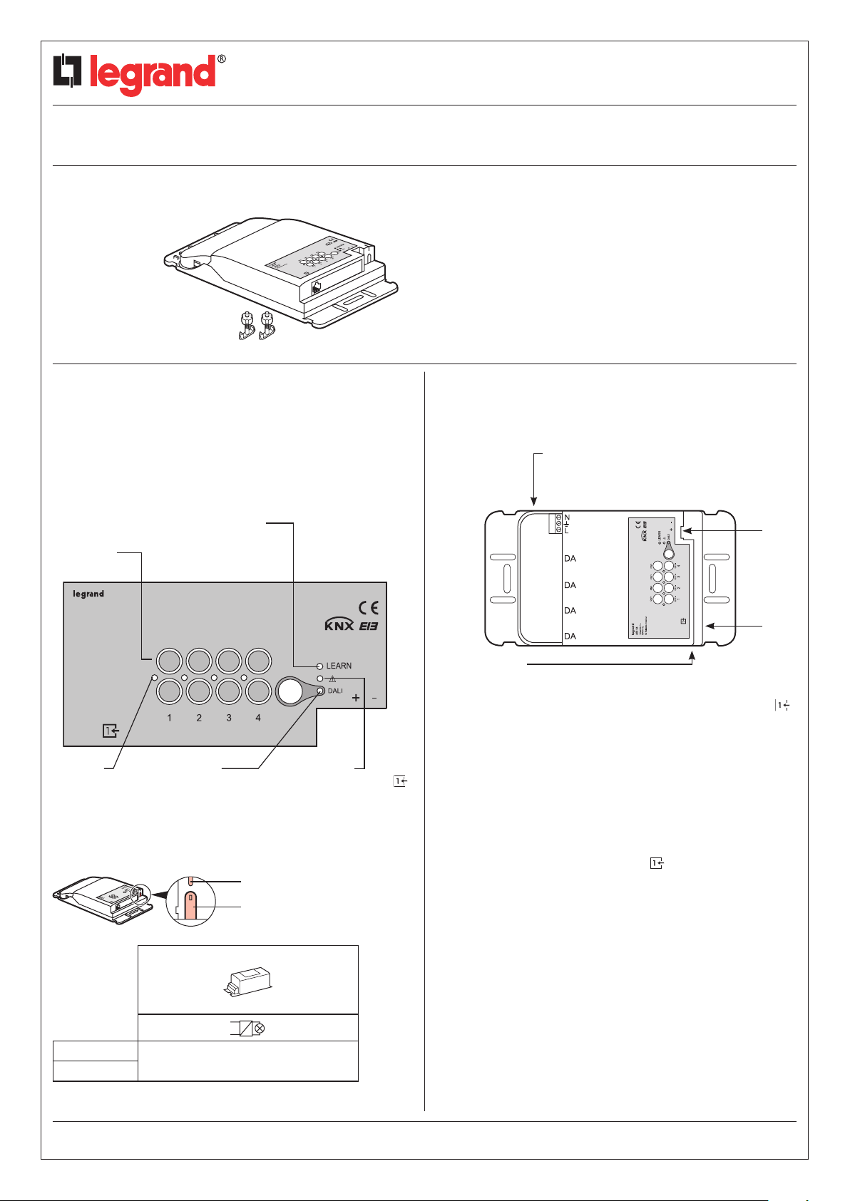
LEARN LED:
indicates the learning
Control
buttons
phase or RESET
Catalogue number(s): 0 488 64
CONTENTS Page
1. Use ............................1
2. Technical characteristics ...........1
3. Dimensions......................2
4. Connection ......................2
5. Installation ......................3
6. Parameter setting .................4
7. Communication objects ............4
8. Care ...........................6
9. Standards .......................6
2. TECHNICAL CHARACTERISTICS (continued)
Voltage: 100-240 V~
Frequency: 50/60 Hz
No load power consumption: 2.4 W
Power side
Power supply: 2 x 2.5 mm2 (screw terminals)
DALI 1.5 mm
2
KNX
Indicators
(on if output
activated)
1 DALI ballast
DALI LED:
indicates the
learning phase or
RESET of the
DALI or DSI ballasts
1
Red LED:
indicates that the BUS
capacity has been exceeded
"PROG & RESET LED"
"PROG & RESET button"
BUS
Control side
• BUS
Connection between the compatible peripherals in the offer and
the controller: RJ 45 cord or BUS cable to fit RJ 45 connector (
max. 150 m between the controller and the furthest peripherals)
• KNX
Connection between the controller and products in the KNX offer:
KNX cable fitted with red, black KNX connector (350 m max. of
cable between the power supply and the furthest product. Beyond
this distance, repeaters must be used.)
The product incorporates positive safety
- If there is a peripheral fault on the BUS ,
the lights come back on automatically after 10 minutes.
Product installation: in a suspended ceiling or on a suitable cable tray
230 V~
110 V~
32 ballasts max./channel
Technical data sheet: S000064192EN-3
CONTENTS
Updated: 29/10/2015 Created: 03/05/2012
1/6
Page 2
Controller - 4 x DALI circuits -
BUS/KNX
Catalogue number(s): 0 488 64
2. TECHNICAL CHARACTERISTICS (continued)
Peripherals compatible with the KNX offer:
- BUS sensors: infrared, ultrasound or dual technology
- Pushbutton lighting controls, switch and scenario management
multifunction controls.
200 mA
Usage temperature: -5°C to +45°C
Storage temperature: -20°C to +70°C
Weight: 525 g
Impact resistance: IK04
Penetration by solid and liquid matter: IP20
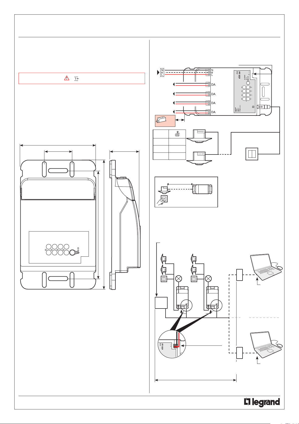
3. DIMENSIONS
147
50
50
4. CONNECTION
All the wiring must be carried out with the mains power off.
BUS/KNX connection
D
X 32
max./out
D
100 m 0.5 mm
150 m 0.75 mm
300 m 1.5 mm
2
2
2
L max = 150 m
240
275
Schematic diagram
BUS/KNX power supply
Cat. No. 0 035 12
Controllers
BUS/KNX connection
IP communication
module
Cat. No. 0 035 43
OR
BUS/KNX - USB
interface
Cat. No. 0 035 47
ETS
software
Scenario 1:
Scenario 2:
ETS
software
350 m max.
Technical data sheet: S000064192EN-3 Updated: 29/10/2015 Created: 03/05/2012
CONTENTS
2/6
Page 3
Controller - 4 x DALI circuits -
BUS/KNX
Catalogue number(s): 0 488 64
4. CONNECTION (continued)
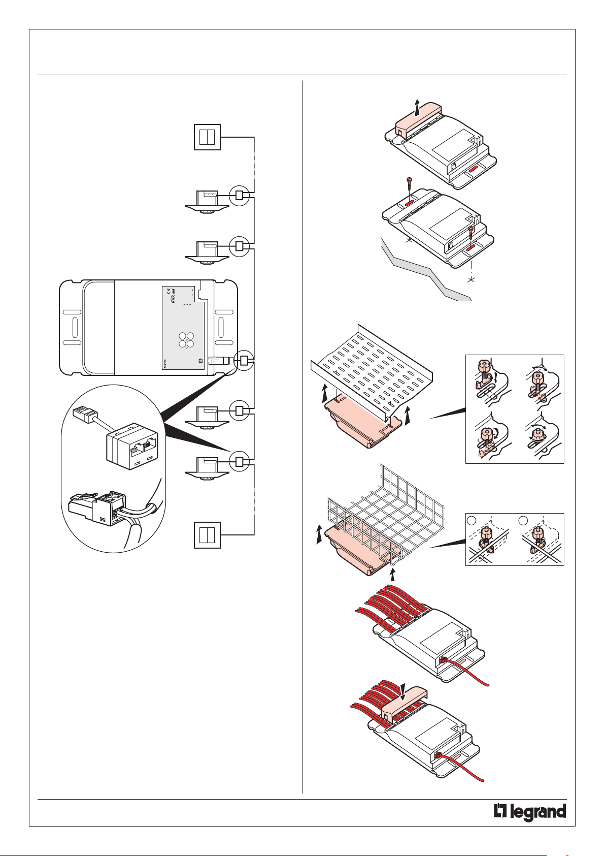
Using double connector Cat. No. 0 488 68
5. INSTALLATION
1
Mounting
On cable tray
2
2
1
1/4
2
Cat. No. 0 488 68
or
Cat. No. 0 488 72
Connects directly to the controller
and/or sensor.
2
3
3
1/4
A W
4
4
Technical data sheet: S000064192EN-3 Updated: 29/10/2015 Created: 03/05/2012
CONTENTS
3/6
Page 4
Controller - 4 x DALI circuits -
BUS/KNX
Catalogue number(s): 0 488 64
6. PARAMETER SETTING
NB: All the wiring must be carried out with the mains power off.
Switching the controller on generates an automatic configuration.
Configuring the controller means that the wiring can be checked.
Compatible peripheral(s) and the controller recognise one another on
their BUS . All sensors control all loads.
The KNX system must be configured using a PC with ETS software
installed. This means each peripheral can be connected to its load.
Technical documentation regarding KNX product settings is integrated
in the ETS database available from January 2012.
Pro Relations department: 0810 48 48 48 48 (local call rate in
France) Mon-Fri 8 am-6 pm
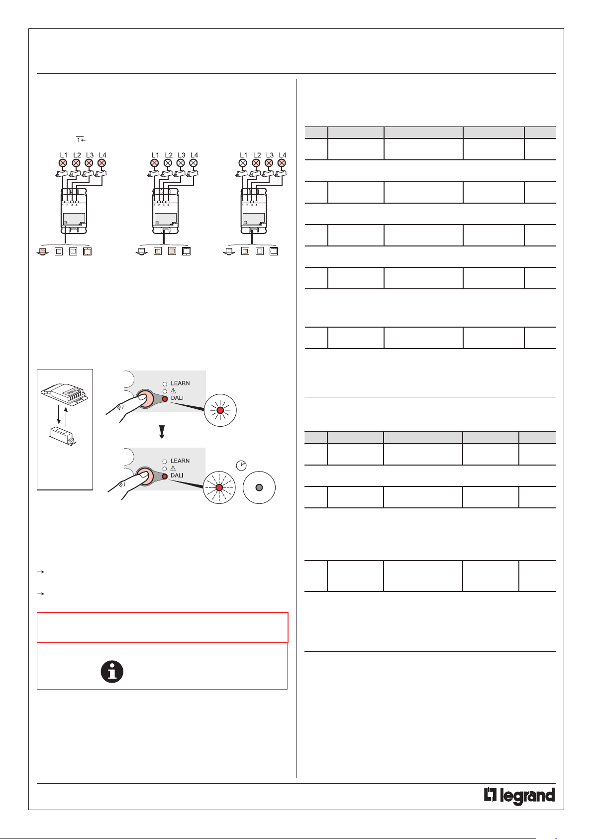
1 The LED
flashes slowly
7. COMMUNICATION OBJECTS
7.1 BUS/KNX ceiling-mounting controllers for dimming
(DALI protocol)
Obj. Function Object name Type Flag
0 On/Off NRC Ch1– IN_ON/
This object is used for On/Off control of luminaires connected to
controller output 1.
1 +/- Dimming NRC Ch1 – IN_DIM
This object is used to vary the light intensity of all luminaires
connected to controller output 1.
2 Value
This object is used to modify the level of light of all luminaires
connected to controller output 1.
3 On/Off
This object gives access to the status of luminaires connected to
controller output 1. A 1-bit status (On/Off) is sent.
4 Value
This object gives access to the status of luminaires connected to
controller output 1. A status with the value of 1 byte (0…100%) is
sent.
OFF
NRC Ch1 – IN_
LEVEL
NRC Ch1 – OUT_
ON/OFF_STATUS
NRC Ch1 – OUT_
LEVEL_STATUS
1.001 Switch
(1 bit)
3.007 Control_
Dimming (4 bits)
5.001 Scaling
(1 byte)
1.001 Switch
(1 bit)
5.001 Scaling (1
byte)
CW
CW
CW
CRT
CRT
Short press < 1 s
2 The LED
DALI
or
DSI
Long press = 10 s
flashes quickly
3 The LED goes out
after a few seconds
NB: Addressing the DALI channels
DALI ballast: total lighting of all loads, then gradual dimming and
switching off of the loads in a random order
DSI ballast: addressed automatically when switched on
NOTE: Do not install DSI and DALI ballasts
on the same channel.
Note: All technical information is available at
www.legrandoc.com
Obj. Function Object name Type Flag
5 Enable/
Disable
This object is used to block or unblock the output in its present
status. Commands will not be recognised.
14 FAULT
This object is used to signal a fault on channel 1 of the DALI bus. If
the object = 1: Fault (short-circuit, ballast communication, lamp) If
the object = 0: No fault
Warning: The fault is generated after the output has been
controlled.
7 Override
This object is used to control the state of controller output 1 with the
concept of priority:
Bits = 01: Output ON
Bits = 00: Output OFF
Bits = 11: Output forced to ON
Bits = 10: Output forced to OFF
Like for objects 0, 1, 2, 3, 4, 5 and 7 assigned to controller output 1,
objects 8, 9, 10, 11, 12, 13 and 15 are assigned to output 2, objects
16, 17, 18, 19, 20, 21 and 23 are assigned to output 3, etc.
NRC Ch1 – IN_
ENABLE/DISABLE
NRC Ch1 - OUT_
DALI_DEFAULT
NRC Ch1 - IN_
OVERRIDE_ON/OFF
– 2 bits
1.003 Enable
(1 bit)
1.002 Boolean
(1 bit)
2.001 Switch
Control (2 bits)
CW
CRT
CW
Technical data sheet: S000064192EN-3 Updated: 29/10/2015 Created: 03/05/2012
CONTENTS
4/6
Page 5
Controller - 4 x DALI circuits -
BUS/KNX
Catalogue number(s): 0 488 64
7. COMMUNICATION OBJECTS (continued)
Obj. Function Object name Type Flag
32 Scenario NRC-IN_RECALL_
This object is used to call scenes which have been configured on the
controller. Up to 32 scenarios can be configured.
Warning: Each controller output can be controlled in a
maximum of 10 scenarios.
67 Scenario NRC OUT_
This object is used to transmit the scenario numbers configured on
the peripherals connected to the controller.
29 SCHEDULE
This object is used to block all automated control by sensors
connected to the controller.
If the object = 1: The sensors are inactive
If the object = 0: The sensors control the level of light
6 Fault
This object is used to signal a fault on the control bus, a
malfunctioning peripheral or disconnected peripheral.
If the object = 1: Communication fault
If the object = 0: No fault
7.2 Peripherals
* The object numbers for the connected peripherals are assigned
dynamically when the ETS project is created.
The object name is preceded by the 8-digit product identifier.
7.2.1 Switch type multifunction control, 1 and 2 way
- Lighting control mode
Obj. Function Object name Type Flag
* On/Off …. Ch1_CMD_OUT_
This object is used to send the ON/OFF telegram generated by a
short press on the control unit.
* Dimming +/- …. – Ch1_CMD_
This object is used to send the dimming telegram generated by a
long press > 0.5 s on the control unit.
* Value
This object is used to manage feedback of information about the
control unit.
Byte = 0 blue LED
Byte ≠ 0 pink LED
* On/Off
This object is used to manage feedback of information about the
control unit.
Bit = 0 blue LED
Bit = 1 pink LED
SCENARIO
SCENARIO
NRC IN_
SCHEDULE_
AUTOMATION
NRC OUT_BUS_
DEFAUT
ON/OFF
OUT_DIM
…. – Ch1_CMD_IN_
LEVEL_STATUS
…. – Ch1_CMD_IN_
ON/OFF_STATUS
17.001
SceneControl
(1 byte)
17.001
SceneControl
(1 byte)
1.003 Enable
(1 bit)
1.002 Boolean
(1 bit)
1.001 Switch
(1 bit)
3.007 Control_
Dimming (4
bits)
5.001 Scaling
(1 byte)
1.001 Switch
(1 bit)
CW
CRWTU
CW
CRT
CT
CT
CRW
CRW
7. COMMUNICATION OBJECTS (continued)
- Shutter control mode
Obj. Function Object name Type Flag
* Up/Down …. Ch1_CMD_SHT_
This object is used to send the telegram generated by a long press
> 0.5 s on the control unit.
Bit = 0 The shutter goes up
Bit = 1 The shutter goes down
* Step/Stop …. Ch1_CMD_SHT_
This object is used to send, with a short press, the Stop telegram if
the shutter is moving and the Step down telegram if the shutter is
stationary.
* Status
This object is used to manage feedback of information about the
control unit.
Byte = 0 blue LED
Byte ≠ 0 pink LED
These communication objects are available for each control unit.
7.2.2 ON/OFF lighting controls, 1 and 2 way
- Lighting control mode
Obj. Function Object name Type Flag
* On/Off …. Ch1_CMD_OUT_
This object is used to send the ON/OFF telegram generated by a
short press on the control unit.
* Dimming +/- …. – Ch1_CMD_
This object is used to send the dimming telegram generated by a
long press > 0.5 s on the control unit.
* Value
This object is used to manage feedback of information about the
control unit.
Byte = 0 blue LED
Byte ≠ 0 pink LED
* On/Off
This object is used to manage feedback of information about the
control unit.
Byte = 0 blue LED
Byte = 1 pink LED
These communication objects are available for each control unit.
7.2.3 Light level measurement cell
Obj. Function Object name Type Flag
* LUX …. – Ch1_OUT_LUX
This object is used to transmit the level of light measured by the light
level cell (0…65535 lux).
OUT_UP/DOWN
OUT_STOP
…. Ch1_CMD_SHT_
IN_POS_STATUS
ON/OFF
OUT_DIM
…. – Ch1_CMD_IN_
LEVEL_STATUS
… .– Ch1_CMD_IN_
ON/OFF_STATUS
1.008 Up/Down
(1 bit)
1.009 Switch
(1 bit)
5.001 Scaling
(1 byte)
1.001 Switch
(1 bit)
3.007 Control_
Dimming (4 bits)
5.001 Scaling (1
byte)
1.001 Switch
(1 bit)
9.004 Lux
(2 bytes)
CT
CT
CRW
CT
CT
CRW
CRW
CT
Technical data sheet: S000064192EN-3 Updated: 29/10/2015 Created: 03/05/2012
CONTENTS
5/6
Page 6
Controller - 4 x DALI circuits -
BUS/KNX
Catalogue number(s): 0 488 64
7. COMMUNICATION OBJECTS (continued)
7.2.4 Wall-mounting sensors (flush or surface), ceiling-mounting
sensors, surface-mounting sensors
Obj. Function Object name Type Flag
* Presence …. – Ch1_SENSOR_
This object is used to send a telegram concerning presence and end
of presence.
If object = 1: Presence detected
If object = 0: End of presence
Warning: End of presence is sent at at the end of the sensor
time delay.
* Presence …. – Ch1_SENSOR_
This object is used to receive a detection frame from another sensor.
If object = 1: Presence
If object = 0: End of presence
* On/Off
This object is used to send the ON/OFF telegram to the actuator.
Warning: Whether this object is sent depends on the sensor
parameter setting mode.
* On/Off
This object is used to feed back the load status for On/Off closed
loop regulation.
Warning: When the Level-Status object is connected, this object
cannot be used.
* Value
This object is used to check the level of a load as a percentage. This
object is used for dimming regulation (open or closed loop).
* Value
This object is used to feed back the load status for dimming closed
loop regulation.
Warning: When the ON/OFF-Status object is connected, this
object cannot be used.
* LUX
This object is used for the link with an external light level cell in the
case of open loop regulation (internal measurement is disabled).
Warning: When the sensor is operating in open loop mode, a
calibration phase with luxmeter is compulsory.
* SYNCHRO-
NISATION
This object is used to integrate a manual control in the control loop.
It must be linked to the control object “CH_CMD_OUT_ON/OFF”.
Warning: If the object is not used, following a command the
sensor will always cut off regulation and switch to override
mode.
OUT_OCC/
UNOCC
IN_OCC/UNOCC
…. – Ch1_SENSOR_
OUT_ON/OFF
…. – Ch1_SENSOR_
IN_ON/OFF_
STATUS
…. – Ch1_SENSOR_
OUT_LEVEL
…. – Ch1_SENSOR_
IN_LEVEL_
STATUS
… .– Ch1_SENSOR_
IN_LUX
…. – Ch1_SENSOR_
IN_SYNCHRO
1.018
Occupancy
(1 bit)
1.018
Occupancy
(1 bit)
1.001 Switch
(1 bit)
1.001 Switch
(1 bit)
5.001 Scaling
(1 byte)
5.001 Scaling
(1 byte)
9.004 Lux (2
bytes)
1.001 Switch
(1 bit)
WT
CWT
CT
CRW
CT
CRW
CRW
CW
8. CARE
Do not use: acetone, tar-removing cleaning agents or
trichloroethylene.
Resistant to the following products: - Hexane (EN 60669-1)
- Methylated spirit
- Soapy water
- Diluted ammonia
- Bleach diluted to 10%
- Window-cleaning products
WARNING: Always test before using other special cleaning
products.
9. STANDARDS
Directive: CE
Installation standards: NFC 15-100
Product standards: IEC 60669-2-1
Environmental standards:
- EU Directive 2002/96/EC:
WEEE (Waste Electrical and Electronic Equipment)
- EU Directive 2002/95/EC:
RoHS (Restriction of Hazardous Substances)
- Decrees and/or regulations: Public buildings
Workplace buildings
High-rise buildings
Technical data sheet: S000064192EN-3 Updated: 29/10/2015 Created: 03/05/2012
CONTENTS
6/6
 Loading...