

LEGRAND 0 488 51 Quick Start Manual
87045 LIMOGES Cedex
Telephone: (+33) 05 55 06 87 87 - Fax: (+33) 05 55 06 88 88
2-output DALI controller
1. USE
This device is a power unit used for managing DALI/DSI lighting and
ventilation loads.
It must be connected to one or more detectors and/or "pushbutton
type" diverted auxiliary controls in order to operate.
It has 3 main operating modes:
- "Corridor side/window side": 3 modes
- "Surrounding area": 1 mode
- "Synchronised": 1 mode (used in public buildings)
page 4
details on page 4
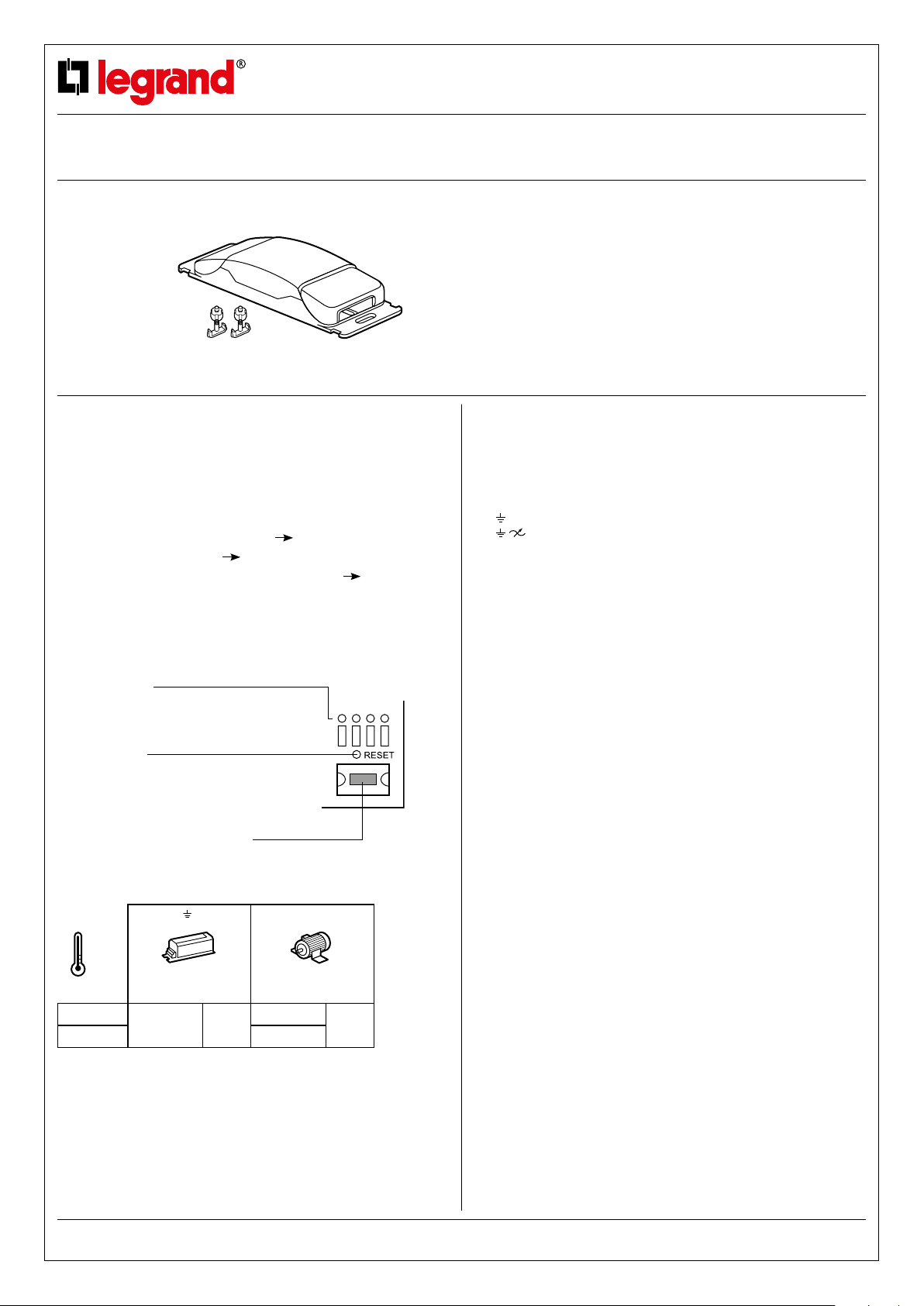
2. TECHNICAL FEATURES
Green indicators:
Indicate the 5 operating modes
Green indicator:
Indicates the learning or RESET phase
Button: RESET or
select from the 5 operating modes
+ 45°C
- 5°C
230 V~
110 V~ 1 x 250 VA
N/ /L1 NO/C/NC
DALI/DSI
(16x2) max/out
1000 VA 4,3 A
details on page 4
1 x 500 VA
details on
2.1 A
Catalogue number(s): 0 488 51
CONTENTS Page
1. Use ............................1
2. Technical features ................1
3. Overall dimensions................2
4. Connection ......................2
5. Installation ......................3
6. Operation .......................4
7. Parameter setting .................5
8. Maintenance.....................5
9. Standards .......................5
2. TECHNICAL FEATURES (continued)
Voltage: 100-240 V~
Frequency: 50/60 Hz
No load power consumption: 1.5 W
Wiring:
- Power:
L: 2 x 2.5 mm2 (screw terminals)
N
N : 2 x 2.5 mm2 via bistable relay (screw terminals)
NO C NC: 2 x 1.5 mm2 via bistable relay (screw terminals)
- Control:
Pushbuttons: 1 x 1.5 mm² (screw terminals)
DALI/DSI ballast: 1 x 1.5 mm² (screw terminals)
Connection between detector and controller: RJ 45 cord or cable
or BUS/SCS cable to be fitted with RJ 45 connector (150 m max.
between the controller and the furthest detector)
Product installation: in a suspended ceiling or on a suitable cable tray
BUS detectors:
- Infrared or ultrasound technology or dual technology
- Max. 6 detectors at 110/230 V~
Pushbutton: - Via normally open contact
Usage temperature: -5°C to +45°C
Storage temperature: -20°C to +70°C
Weight: 256 g
Impact resistance: IK04
Penetration by solid and liquid matter: IP20
(100 m max. between the controller and the
pushbutton)
(16 ballasts max. per channel) the distance
depends on the type of cable used.
The product is specifically for DALI or DSI,
which is selected automatically.
- Can be used with an indicator: voltage, 27 V= to display
the state of the load in synchronised mode
Note: It is advisable not to exceed 5 pushbuttons per
channel (consumption of indicators)
Technical data sheet: S000067167EN-3
Updated on: 24/08/2015 Created on: 10/01/2012
1/4
2-output DALI controller
Catalogue number(s): 0 488 51
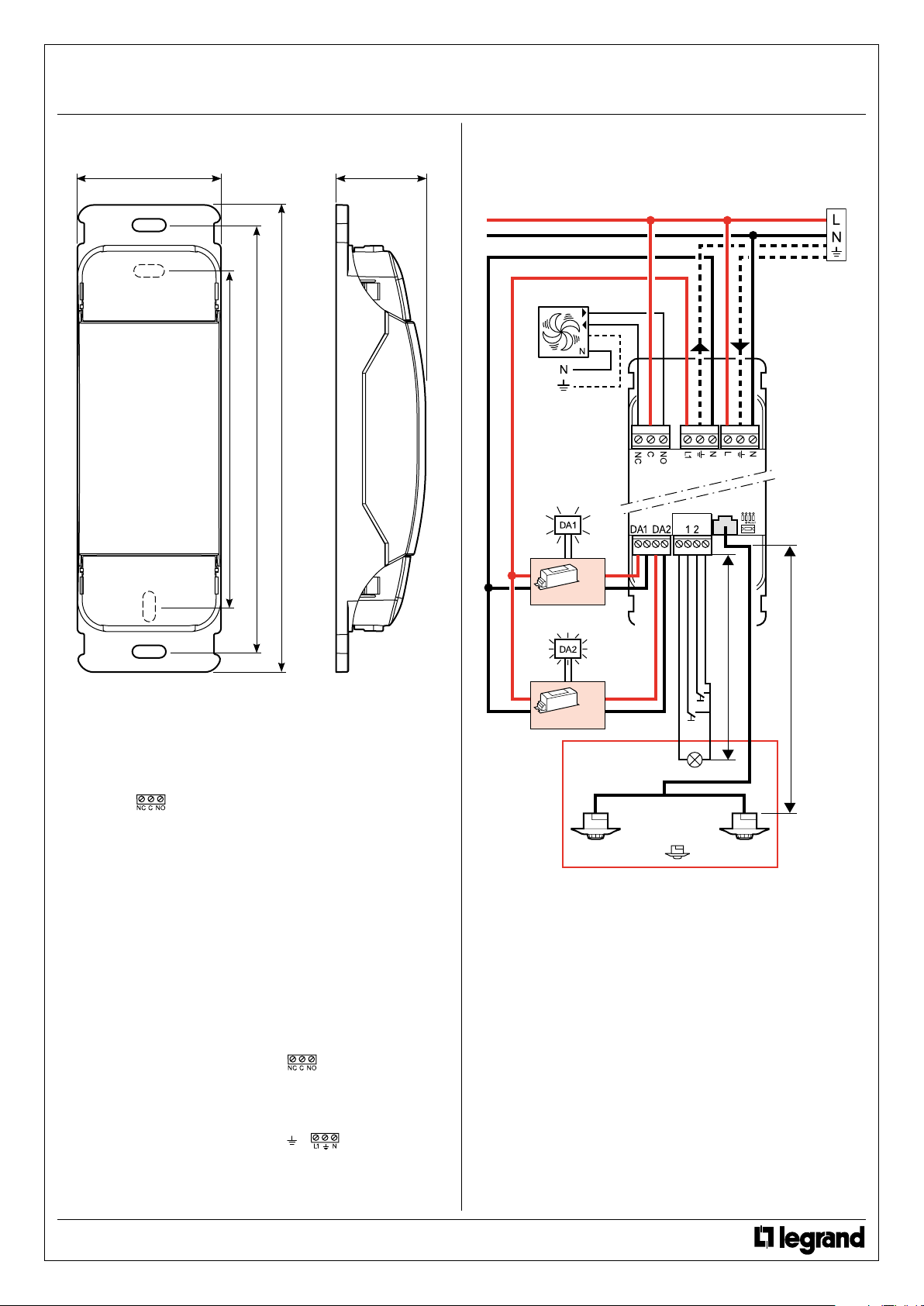
3. OVERALL DIMENSIONS
71 44
168
210
4. CONNECTION (continued)
4.1 Wiring 1 (on a single phase)
Ventilation
231
/OUT
x16 max.
4. CONNECTION
The NC C NO ( ) output on the controller is always associated
with the presence information on the detectors. At the 1st detection,
the relay closes and opens at the end of the time delay set on the
detector.
This output can be used to activate a socket unit, a ventilation unit
and any other system via a contactor or for emergency lighting (see
diagram on p.3).
If one of the phases is cut off in an installation with two separate
phases, the other phase will continue to supply its associated lighting
circuit in mode 4.
In the event of a connection fault between the detector(s) and
controller, the lights will automatically come back on at 100% after
10 minutes.
If the controller fails, the level of the DALI ballasts will be maintained.
The controller has a status memory, which means that when the mains
power returns, it will return to the status it was in before the break for both
DALI channels. The state of the NC C NO (
as all that is necessary to trigger it is a detection. (If the controller has a
detector and there is no-one present after the mains power returns, the
system will switch off at the end of the time delay set on the detector).
) relay is not memorised
/OUT
x16 max.
100 m max.
150 m max.
230/110 V: x 6 max.
To save more energy, the power relay L1
DALI ballast(s) opens 5 minutes after the end of the time delay set on
the detector (apart from in public building mode).
L ( ) supplying the
Technical data sheet: S000067167EN-3 Updated on: 24/08/2015 Created on: 10/01/2012
CONTENTS
2/5
 Loading...