

Page 1
Unité de Protection
Réf. 0 281 64/65/66/67/68
Juin 17
LE08438AB
Page 2

Page 3

Table des matières
1. Identification et réglages par défaut ..... 4
2. Réglage des niveaux de protection ...... 6
3.
Signalement de l'état de l'unité de protection
4. Bouton de Test....................... 10
5. Visualisation et utilisation des menus .... 11
6. Page par défaut ..................... 12
7. Visualisation des réglages des courants .... 14
8. Pages menu ........................ 15
9. Accessoires ......................... 16
10. Sélectivité logique ................... 19
.. 9
11. Navigation dans les menus ............ 21
12. Structure des menus ................. 26
Version FW: P1611, TXXH GLXX DMX
3
3
Page 4
Unité de Protection
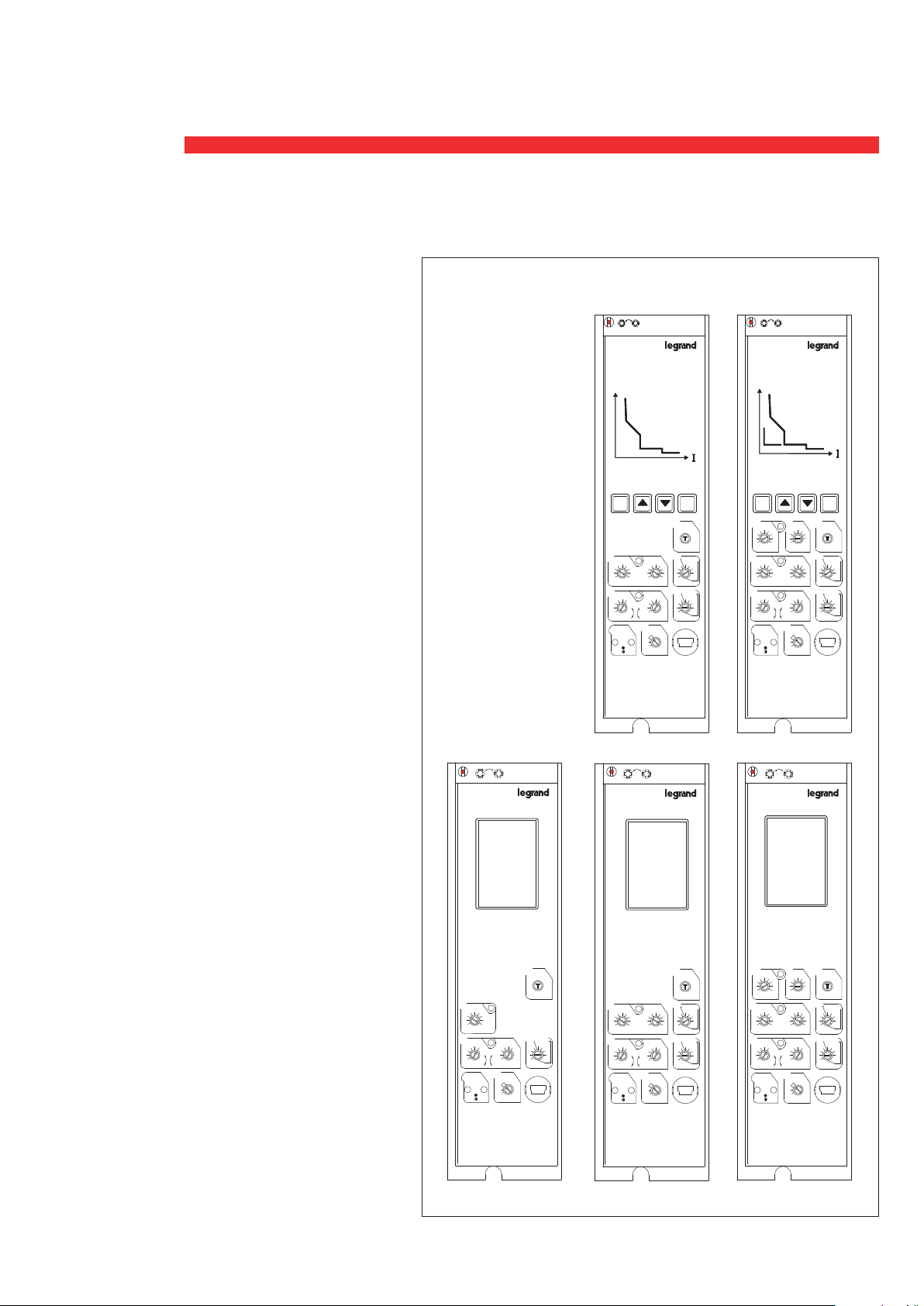
1. Identification et réglages par défaut
0 281 64
TYPE LCD AVEC
PROTECTION LI
réglages par défaut
Ii=Icw;
Ir=(0.9+0.1) xIn;
Isd=10 x Ir fixe;
tsd=0.1s fixe;
tr=5s (MEM=OFF);
N=100%;
0 281 65
TYPE LCD AVEC
PROTECTION LSI
réglages par défaut
Ii=Icw;
Isd=10 x Ir;
tsd=0.1s (t=const);
Ir=(0.9+0.1) xIn;
tr=5s (MEM=OFF);
N=100%;
0 281 66
TYPE LCD AVEC
PROTECTION LSIg
réglages par défaut
Ig=0.2×In
tg=0.1 @ t=const
li=Icw;
Isd=10 x Ir;
tsd=0.1s (t=const);
Ir=(0.9+0.1) xIn;
tr=5s (MEM=OFF);
N=100%;
MAN
AUT
0 281 64
AUT
MAN
t
OK C
lsd
li
4
5
6810
3
2.5
6
12
4
3
2
lr
0.7
0.6
0.5
0.4
ON
8
2
15
10
lcw
1.5
x
x
ln
lr
0.08
0.8
0.06
0.9
0.1
0.04
0.02
+
0.00
x
ln
N
100%
x
lr
50%
l>.90
OFF
l>1.05
MAN
AUT
0 281 67
test
tsd
l
1
0.5
0.2
0.1
tr
MEM-OFF
30
20
10
5
@6I
0 281 65
2
t=k@12lr
1
30
AUT
MAN
0 281 68
t
OK C
lg
tg
test
1
0.6
1
0.5
0.7
0.5
0.5
0.8
0.4
0.3
0.2
0.5
0.2
0.1
s
20
10
5
r
s
li
6810
4
3
2
lr
0.7
0.6
0.5
0.4
ON
1 0.1
OFF
12
15
lcw
x
ln
0.8
0.9
x
lr
l>.90
l>1.05
MAN
0.2
0.2
0.1
2
tsd
lsd
l
t=k@12lr
1
4
5
1
0.5
3
2.5
6
0.5
0.2
8
2
1.5
0.06
0.04
0.02
+
0.00
N
100%
50%
OFF
AUT
0.1
0.2
10
0.1
x
lr
s
tr
MEM-OFF
0.08
30
20
30
0.1
20
10
10
5
5
@6I
r
s
x
ln
0 281 66
0 281 67
TYPE BASIC
PROTECTION LSI
réglages par défaut
Ii=Icw; Isd=10 x Ir;
tsd=0.1s (t=const);
Ir=(0.9+0.1) xIn;
tr=5s (MEM=OFF);
N=100%;
0 281 68
TYPE BASIC AVEC
PROTECTION LSIg
réglages par défaut
Ig=0.2×In
tg=0.1 @ t=const
li=Icw;
test
li
6810
12
4
15
3
lcw
2
x
ln
tr
lr
0.8
0.9
0.7
0.6
0.5
+
0.4
x
lr
ON
l>.90
l>1.05
MEM-OFF
0.08
30
20
0.06
30
0.1
20
0.04
0.02
0.00
N
100%
50%
OFF
10
10
5
5
@6I
r
s
x
ln
li
6810
4
3
2
x
lr
0.8
0.9
0.7
0.6
0.5
0.4
ON
l>.90
l>1.05
test
2
tsd
lsd
l
t=k@12lr
1
4
5
1
0.5
3
2.5
6
0.5
12
2
15
lcw
1.5
ln
0.06
0.04
0.02
+
0.00
N
100%
x
lr
50%
OFF
0.2
8
0.1
0.2
10
0.1
x
lr
s
tr
MEM-OFF
0.08
30
20
30
0.1
20
10
10
5
5
@6I
r
s
x
ln
lg
0.4
0.3
0.2
li
4
3
2
lr
0.7
0.6
0.5
0.4
ON
0.6
0.5
6810
0.8
0.7
0.8
1 0.1
0.2
OFF
lsd
2.5
12
15
lcw
1.5
x
ln
0.9
0.04
0.02
+
0.00
N
100%
x
lr
50%
l>.90
OFF
l>1.05
tg
test
1
1
0.5
0.5
0.2
0.1
2
tsd
l
t=k@12lr
1
4
5
1
0.5
3
6
0.5
0.2
8
2
0.06
0.1
0.2
10
0.1
x
lr
s
tr
MEM-OFF
0.08
30
20
30
0.1
20
10
10
5
5
@6I
r
s
x
ln
Isd=10 Ir;
tsd=0.1s (t=const);
Ir=(0.9+0.1) xIn;
tr=5s (MEM=OFF);
N=100%;
MEM OFF=
Mémoire thermique désactivée
4
Page 5
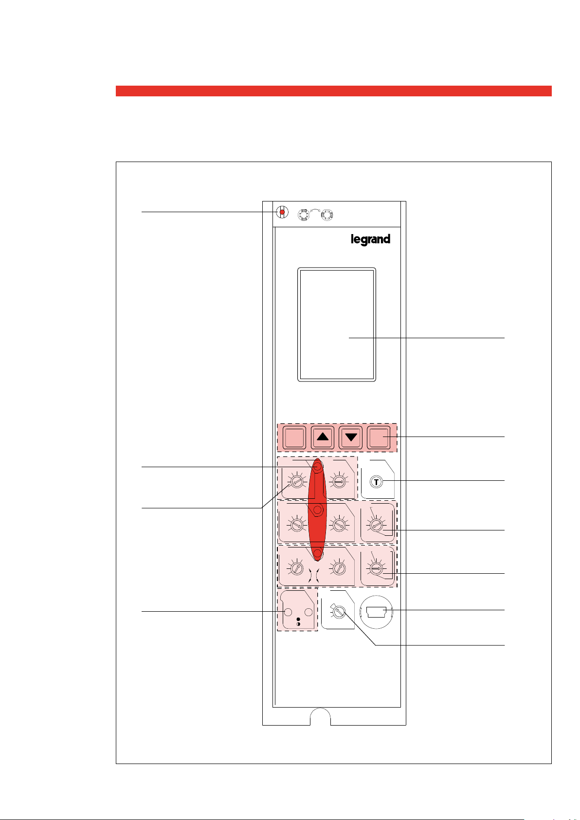
Unité de Protection
SÉLECTEUR RESET
MAN-AUT
VOYANTS INDICATEURS
DE DÉCLENCHEMENT
PROTECTION CONTRE
LES DÉFAULTS DE TERRE
VOYANT DE SIGNALISATION
DE L'ETAT DE L'UNITÉ
DE PROTECTION
MAN
AUT
0 281 66
OK C
lg
0.6
0.5
0.4
0.3
0.2
li
6810
4
3
2
lr
0.8
0.7
0.6
0.5
0.4
ON
tg
0.7
0.5
0.8
0.2
1 0.1
0.1
OFF
lsd
2.5
12
2
15
lcw
1.5
x
ln
0.06
0.9
0.04
0.02
+
0.00
N
100%
x
lr
50%
l>.90
OFF
l>1.05
1
1
0.5
0.2
4
5
3
6
8
10
x
lr
0.08
0.1
x
ln
ÉCRAN LCD
BOUTONS DE
NAVIGATION MENU
test
BOUTON TEST
DÉCLENCHEMENT
PROTECTION
2
tsd
l
t=k@12lr
1
1
0.5
0.5
0.2
0.1
0.2
0.1
s
tr
MEM-OFF
30
20
30
20
10
10
5
5
@6I
r
s
MAGNÉTIQUE
INSTANTANÉE
(COURTE DURÉE)
PROTECTION
THERMIQUE
(LONGUE DURÉE)
USB
PROTECTION
DU NEUTRE
5
Page 6
Unité de Protection
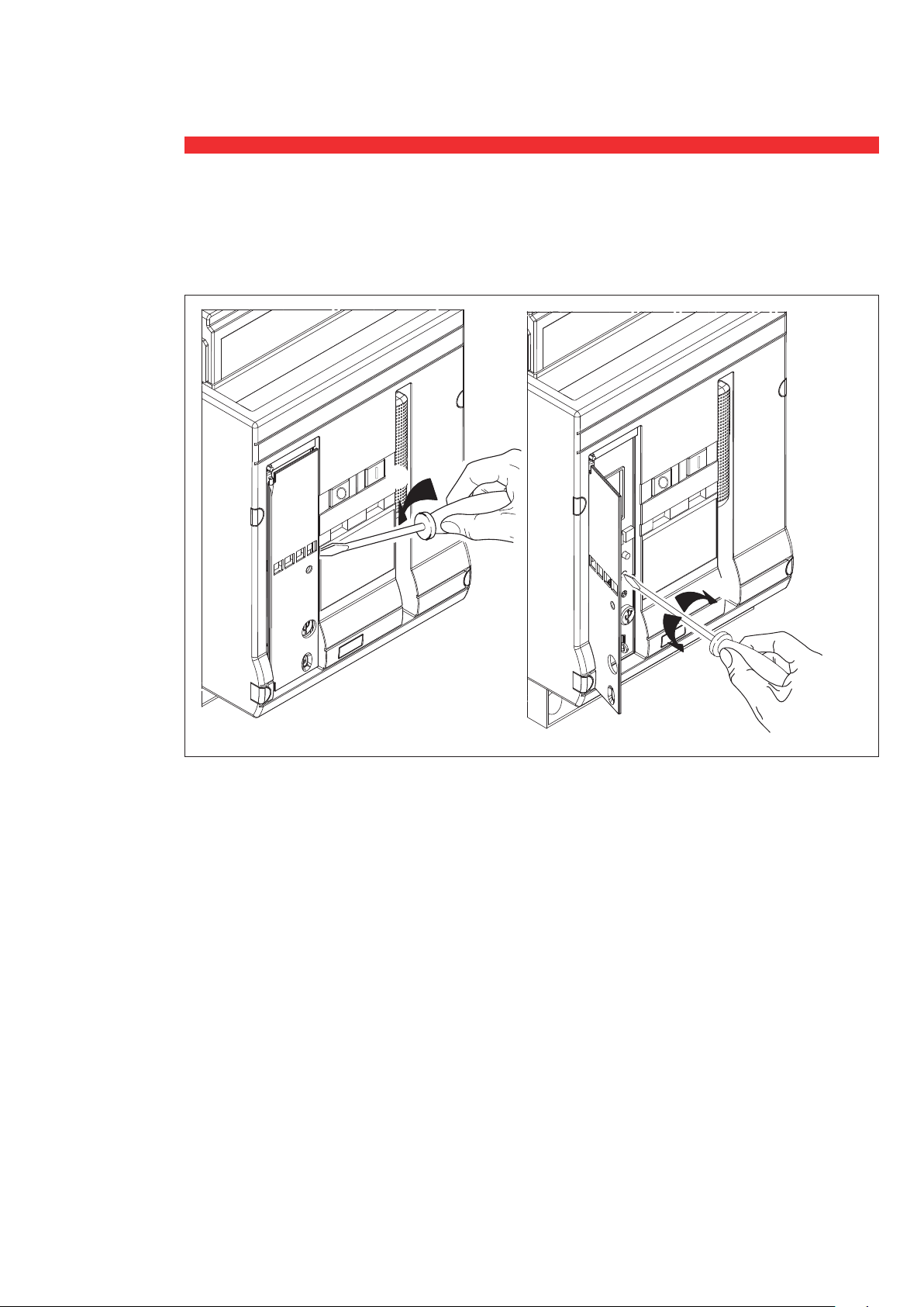
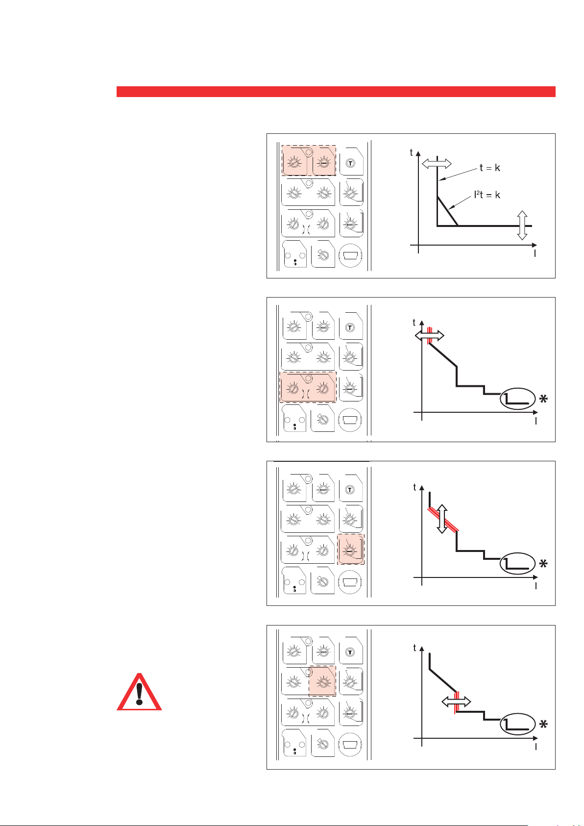
2. Réglage des niveaux de protection
Le réglage des niveaux de protection s’effectue à l’aide de commutateurs rotatifs. Effectuer le réglage
à l’aide d’un tournevis à tête plate.
6
Page 7
0 281 66
OK C
0 281 66
MAN
AUT
@6I
0.3
0.2
0.4
0.5
0.6
0.7
0.8
1 0.1
0.2
0.5
1
0.1
0.2
0.5
1
lg
tg
test
2
3
4
6810
12
15
lcw
li
x
ln
1.5
2.5
2
3
4
5
6
8
10
x
lr
lsd
OFF
0.1
0.2
0.5
1
1
0.5
0.2
0.1
s
tsd
l
2
t=k@12lr
lr
0.4
0.5
0.6
0.7
0.8
0.9
+
0.00
0.02
0.04
0.06
0.08
0.1
5
10
20
30
30
20
10
5
MEM-OFF
s
r
tr
N
100%
50%
OFF
x
ln
ON
x
lr
l>.90
l>1.05
@6I
0 281 66
0.3
0.2
0.4
0.5
0.6
0.7
0.8
1 0.1
0.2
0.5
1
0.1
0.2
0.5
1
lg
tg
test
2
3
4
6810
12
15
lcw
li
x
ln
1.5
2.5
2
3
4
5
6
8
10
x
lr
lsd
OFF
0.1
0.2
0.5
1
1
0.5
0.2
0.1
s
tsd
l
2
t=k@12lr
lr
0.4
0.5
0.6
0.7
0.8
0.9
+
0.00
0.02
0.04
0.06
0.08
0.1
5
10
20
30
30
20
10
5
MEM-OFF
s
r
tr
N
100%
50%
OFF
x
ln
ON
x
lr
l>.90
l>1.05
OK C
0 281 66
MAN
AUT
OK C
0 281 66
MAN
AUT
OK C
@6I
0.3
0.2
0.4
0.5
0.6
0.7
0.8
1 0.1
0.2
0.5
1
0.1
0.2
0.5
1
lg
tg
test
2
3
4
6810
12
15
lcw
li
x
ln
1.5
2.5
2
3
4
5
6
8
10
x
lr
lsd
OFF
0.1
0.2
0.5
1
1
0.5
0.2
0.1
s
tsd
l
2
t=k@12lr
lr
0.4
0.5
0.6
0.7
0.8
0.9
+
0.00
0.02
0.04
0.06
0.08
0.1
5
10
20
30
30
20
10
5
MEM-OFF
s
r
tr
N
100%
50%
OFF
x
ln
ON
x
lr
l>.90
l>1.05
0 281 66
OK C
0 281 66
MAN
AUT
OK C
MAN
AUT
@6I
0.3
0.2
0.4
0.5
0.6
0.7
0.8
1 0.1
0.2
0.5
1
0.1
0.2
0.5
1
lg
tg
test
2
3
4
6810
12
15
lcw
li
x
ln
1.5
2.5
2
3
4
5
6
8
10
x
lr
lsd
OFF
0.1
0.2
0.5
1
1
0.5
0.2
0.1
s
tsd
l
2
t=k@12lr
lr
0.4
0.5
0.6
0.7
0.8
0.9
+
0.00
0.02
0.04
0.06
0.08
0.1
5
10
20
30
30
20
10
5
MEM-OFF
s
r
tr
N
100%
50%
OFF
x
ln
ON
x
lr
l>.90
l>1.05
@6I
0 281 66
0.3
0.2
0.4
0.5
0.6
0.7
0.8
1 0.1
0.2
0.5
1
0.1
0.2
0.5
1
lg
tg
test
2
3
4
6810
12
15
lcw
li
x
ln
1.5
2.5
2
3
4
5
6
8
10
x
lr
lsd
OFF
0.1
0.2
0.5
1
1
0.5
0.2
0.1
s
tsd
l
2
t=k@12lr
lr
0.4
0.5
0.6
0.7
0.8
0.9
+
0.00
0.02
0.04
0.06
0.08
0.1
5
10
20
30
30
20
10
5
MEM-OFF
s
r
tr
N
100%
50%
OFF
x
ln
ON
x
lr
l>.90
l>1.05
OK C
@6I
0 281 66
0.3
0.2
0.4
0.5
0.6
0.7
0.8
1 0.1
0.2
0.5
1
0.1
0.2
0.5
1
lg
tg
test
2
3
4
6
8
10
12
15
lcw
li
x
ln
1.5
2.5
2
3
4
5
6
8
10
x
lr
lsd
OFF
0.1
0.2
0.5
1
1
0.5
0.2
0.1
s
tsd
l
2
t=k@12lr
lr
0.4
0.5
0.6
0.7
0.8
0.9
+
0.00
0.02
0.04
0.06
0.08
0.1
5
10
20
30
30
20
10
5
MEM-OFF
s
r
tr
N
100%
50%
OFF
x
ln
MAN
AUT
ON
x
lr
l>.90
l>1.05
OK C
0 281 66
MAN
AUT
OK C
Unité de Protection
Protection contre les défaults
de terre (uniquement pour
réf. 0 281 66 et 0 281 68)
Réglage du courant (9 paliers)
Ig=0,2-0,3-0,4-0,5-0,6-0,7-0,8-1
lg
0.4
0.3
0.2
li
×In-OFF
lr
Temporisation de la protection de
terre (@12×Ig) (4+4 paliers)
0.6
0.5
0.4
tg=0.1-0.2-0.5-1s(t=const)
tg=1-0.5-0.2-0.1s(I2t=const)
Protection contre les
surcharges
Réglage du courant (@12×Ig)
(2x6 paliers)
Ir=0,4÷1×In
Avec 2 commutateurs
(0,4÷0,9, paliers de 0,1
0,0÷0,1, paliers de 0,02)
Exemple :
lg
0.4
0.3
0.2
li
3
lr
0.6
0.5
0.4
Ir =(0,4+0,06)×In= 0,46 In
Temporisation de la protection long
retard (@6Ir) (4+4 phases)
tr=5-10-20-30s (MEM ON)
tr=30-20-10-5s (MEM OFF)
MEM OFF = mémoire thermique Off
MEM ON = mémoire thermique On
Protection contre les
courts-circuits
Réglage courant (9 paliers)
Si Ii < Isd, le réglage instantané
lg
0.4
0.3
0.2
li
3
lr
0.6
0.5
0.4
lg
0.4
0.3
0.2
li
3
lr
0.6
0.5
0.4
prévaut sur le réglage magnétique.
* "Seuil d intervention ultime
non réglable=lsf=Icw@415V"
3
ON
0.5
4
2
0.7
ON
0.5
4
2
0.7
ON
0.5
4
2
0.7
0.5
4
2
0.7
ON
0.6
6810
0.8
0.6
6810
0.8
0.6
6
0.8
0.6
6810
0.8
0.7
0.8
1 0.1
OFF
12
15
lcw
x
ln
0.9
+
x
lr
l>.90
l>1.05
0.7
0.8
1 0.1
OFF
12
15
lcw
x
ln
0.9
+
x
lr
l>.90
l>1.05
0.7
0.8
1 0.1
OFF
8
10
12
15
lcw
x
ln
0.9
+
x
lr
l>.90
l>1.05
0.7
0.8
1 0.1
OFF
12
15
lcw
x
ln
0.9
+
x
lr
l>.90
l>1.05
tg
test
1
1
0.5
0.5
0.2
0.2
0.1
2
tsd
lsd
2.5
2
1.5
0.06
0.04
0.02
0.00
N
100%
50%
OFF
tg
0.5
0.2
0.1
lsd
2.5
2
1.5
0.06
0.04
0.02
0.00
N
100%
50%
OFF
tg
0.5
0.2
0.1
lsd
2.5
2
1.5
0.06
0.04
0.02
0.00
N
100%
50%
OFF
tg
0.5
0.2
0.1
lsd
2.5
2
1.5
0.06
0.04
0.02
0.00
N
100%
50%
OFF
l
t=k@12lr
1
4
5
1
3
0.08
1
1
4
3
0.08
1
1
4
3
0.08
1
1
4
3
0.08
0.5
6
0.5
0.2
8
0.1
0.2
10
0.1
x
lr
s
tr
MEM-OFF
30
20
30
0.1
20
10
10
5
5
@6I
r
x
0.5
5
x
0.1
x
0.5
5
x
0.1
x
0.5
5
x
0.1
x
s
ln
test
0.2
2
tsd
l
t=k@12lr
1
1
0.5
6
0.5
0.2
8
0.1
0.2
10
0.1
lr
s
tr
MEM-OFF
30
20
30
20
10
10
5
5
@6I
r
s
ln
test
0.2
2
tsd
l
t=k@12lr
1
1
0.5
6
0.5
0.2
8
0.1
0.2
10
0.1
lr
s
tr
MEM-OFF
30
20
30
20
10
10
5
5
@6I
r
s
ln
test
0.2
2
tsd
l
t=k@12lr
1
1
0.5
6
0.5
0.2
8
0.1
0.2
10
0.1
lr
s
tr
MEM-OFF
30
20
30
20
10
10
5
5
@6I
r
s
ln
7
Page 8
OK C
0 281 66
MAN
AUT
@6I
0.3
0.2
0.4
0.5
0.6
0.7
0.8
1 0.1
0.2
0.5
1
0.1
0.2
0.5
1
lg
tg
test
2
3
4
6810
12
15
lcw
li
x
ln
1.5
2.5
2
3
4
5
6
8
10
x
lr
lsd
OFF
0.1
0.2
0.5
1
1
0.5
0.2
0.1
s
tsd
l
2
t=k@12lr
lr
0.4
0.5
0.6
0.7
0.8
0.9
+
0.00
0.02
0.04
0.06
0.08
0.1
5
10
20
30
30
20
10
5
MEM-OFF
s
r
tr
N
100%
50%
OFF
x
ln
ON
x
lr
l>.90
l>1.05
OK C
0 281 66
MAN
AUT
OK C
0 281 66
MAN
AUT
@6I
0.3
0.2
0.4
0.5
0.6
0.7
0.8
1 0.1
0.2
0.5
1
0.1
0.2
0.5
1
lg
tg
test
2
3
4
6810
12
15
lcw
li
x
ln
1.5
2.5
2
3
4
5
6
8
10
x
lr
lsd
OFF
0.1
0.2
0.5
1
1
0.5
0.2
0.1
s
tsd
l
2
t=k@12lr
lr
0.4
0.5
0.6
0.7
0.8
0.9
+
0.00
0.02
0.04
0.06
0.08
0.1
5
10
20
30
30
20
10
5
MEM-OFF
s
r
tr
N
100%
50%
OFF
x
ln
ON
x
lr
l>.90
l>1.05
OK C
@6I
0 281 66
0.3
0.2
0.4
0.5
0.6
0.7
0.8
1 0.1
0.2
0.5
1
0.1
0.2
0.5
1
lg
tg
test
2
3
4
6
8
10
12
15
lcw
li
x
ln
1.5
2.5
2
3
4
5
6
8
10
x
lr
lsd
OFF
0.1
0.2
0.5
1
1
0.5
0.2
0.1
s
tsd
l
2
t=k@12lr
lr
0.4
0.5
0.6
0.7
0.8
0.9
+
0.00
0.02
0.04
0.06
0.08
0.1
5
10
20
30
30
20
10
5
MEM-OFF
s
r
tr
N
100%
50%
OFF
x
ln
MAN
AUT
ON
x
lr
l>.90
l>1.05
OK C
0 281 66
MAN
AUT
OK C
Unité de Protection
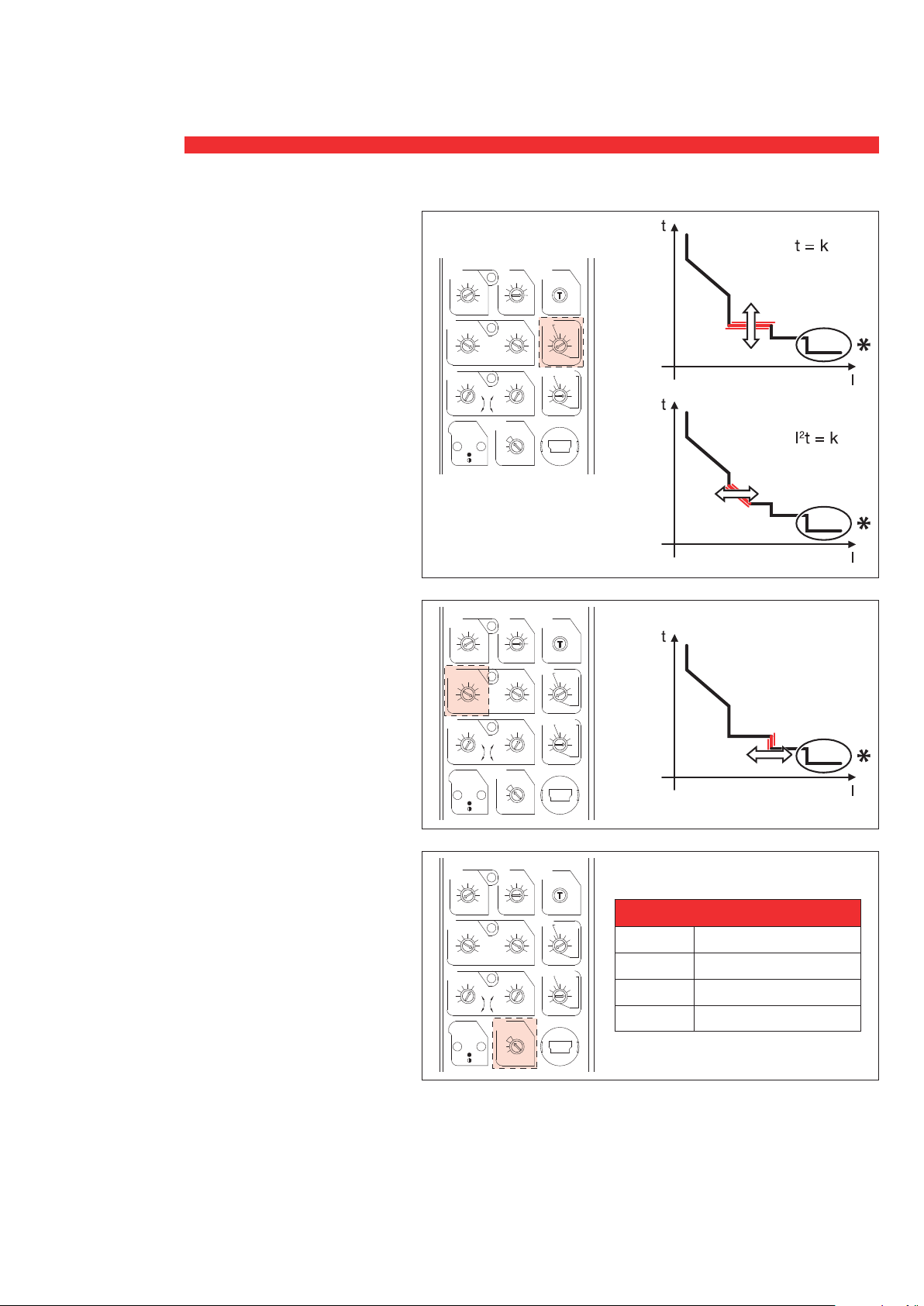
Temporisation de la protection
court retard (4+4 paliers)
Tsd=0.1-0.2-0.5-1s (t=const)
Tsd=1-0.5-0.2-0.1s (I t=const)
lg
0.4
0.3
0.2
li
4
3
2
lr
0.6
0.5
0.4
ON
Protection instantanée contre
les courts-circuits de très
grande intensité
Réglage du courant (9 paliers)
Ii=2-3-4-6-8-10-12-15x In ou Icw
Protection neutre
Réglage courant (3 paliers)
N=OFF-50%-100%
Protection contre surchauffe
(non réglable) t >95°C
* "Seuil d intervention ultime
lg
0.4
0.3
0.2
li
3
2
lr
0.6
0.5
0.4
ON
lg
0.4
0.3
0.2
li
3
2
lr
0.6
0.5
0.4
ON
non réglable=lsf=Icw@415V"
0.7
4
0.7
4
0.7
0.5
0.5
0.5
0.6
6810
0.8
0.6
6
0.8
0.6
6
0.8
8
8
tg
0.7
0.5
0.8
1 0.1
0.2
0.1
OFF
lsd
2.5
12
2
15
lcw
1.5
x
ln
0.06
0.9
0.04
0.02
+
0.00
N
100%
x
lr
50%
l>.90
OFF
l>1.05
tg
0.7
0.5
0.8
1 0.1
0.2
0.1
OFF
lsd
10
2.5
12
2
15
lcw
1.5
x
ln
0.06
0.9
0.04
0.02
+
0.00
N
100%
x
lr
50%
l>.90
OFF
l>1.05
tg
0.7
0.5
0.8
1 0.1
0.2
0.1
OFF
lsd
10
2.5
12
2
15
lcw
1.5
x
ln
0.06
0.9
0.04
0.02
+
0.00
N
100%
x
lr
50%
l>.90
OFF
l>1.05
test
1
1
0.5
0.2
2
tsd
l
t=k@12lr
1
4
5
1
3
0.08
1
1
4
3
0.08
1
1
4
3
0.08
0.5
6
0.5
0.2
8
0.1
0.2
10
0.1
x
lr
s
tr
MEM-OFF
30
20
30
0.1
20
10
10
5
5
@6I
r
x
0.5
5
x
0.1
x
0.5
5
x
0.1
x
s
ln
test
0.2
2
tsd
l
t=k@12lr
1
1
0.5
6
0.5
0.2
8
0.1
0.2
10
0.1
lr
s
tr
MEM-OFF
30
20
30
20
10
10
5
5
@6I
r
s
ln
test
0.2
2
tsd
l
t=k@12lr
1
1
0.5
6
0.5
0.2
8
0.1
0.2
10
0.1
lr
s
tr
MEM-OFF
30
20
30
20
10
10
5
5
@6I
r
s
ln
PROTECTION DU NEUTRE
Position Protection
OFF Non protégé
50% Protégé à 50% Ir-Isd-Ii
100% Protégé à Ir-Isd-Ii
8
Page 9
Unité de Protection
3
4
12
15
2.5
2
6
8
0.2
0.5
0.2
0.1
0 281 66
MAN
AUT
@6I
2
3
4
12
15
lcw
x
ln
1.5
2.5
2
6
8
10
x
lr
0.1
0.2
0.5
0.2
0.1
s
lr
0.4
0.5
0.6
0.7
0.8
0.9
+
0.00
0.02
0.04
0.06
0.08
0.1
5
10
20
30
30
20
10
5
MEM-OFF
s
r
tr
N
100%
50%
OFF
x
ln
ON
x
lr
l>.90
l>1.05
0 281 66
MAN
AUT
OK C
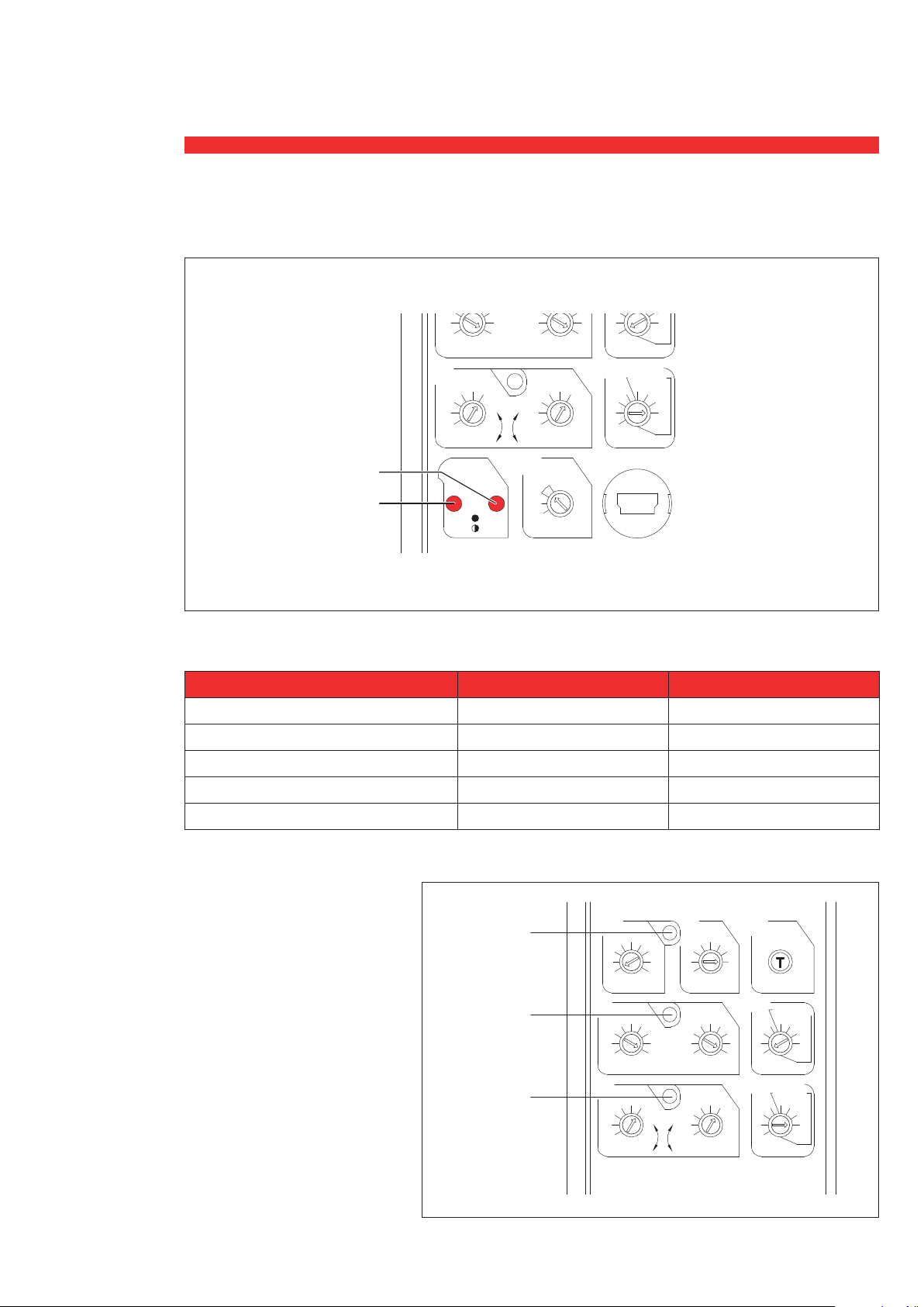
3. Signalisation de l‘état de l‘unité de protection
0.06
0.08
10
0.1
x
lr
tr
0.1
10
x
ln
20
5
MEM-OFF
30
30
@6I
s
20
10
5
r
s
lcw
2
lr
0.8
0.9
0.7
0.6
0.5
0.4
ON
l>.90
l>1.05
VOYANT 2
VOYANT 1
L’état de l’unité de protection est signalé par l’intermédiaire des voyants 1 et 2, conformément au
1.5
x
ln
0.04
0.02
+
0.00
N
100%
x
lr
50%
OFF
tableau ci dessous :
PROTECTION
VOYANT 1 VOYANT 2
Inactif Commuté sur Off Commuté sur Off
Actif: (I ≥ 250A ou alimenté)
Vert Fixe Commuté sur Off
Actif: (pré-alarme surcharge I > 0,9 Ir) Vert Fixe Rouge Fixe
Actif: (alarme surcharge I > 1,05 Ir) Vert Fixe Rouge Clignotement
Actif: (alarme surchauffe T > 75°C) Vert Clignotement Rouge Clignotement
Une alarme est prioritaire sur qu’une pré-alarme. La surcharge est prioritaire sur que la surchauffe.
VOYANT 3
Déclenchment sur dèfault de terre
(uniquement pour réf. 0 281 66
et 0 281 68)
VOYANT 4
Déclenchement sur court-circuit/
court-circuit instantané
VOYANT 5
Déclenchement sur surcharge
ou température
En cas de déclenchement du
disjoncteur, la LED correspondant
à la protection qui a provoqué le
déclenchement reste allumée,
signalant l'erreur correspondante
(si une alimentation externe est
présente).
VOYANT 3
VOYANT 4
VOYANT 5
lg
0.6
0.5
0.4
0.3
0.2
li
8
6
4
3
2
lr
0.8
0.7
0.6
0.5
0.4
tg
0.7
0.8
OFF
10
12
15
lcw
x
ln
0.9
1
0.5
1 0.1
0.2
0.1
lsd
3
2.5
2
1.5
0.06
0.04
0.02
+
0.00
0.08
test
1
0.5
0.2
2
tsd
l
t=k@12lr
4
5
6
10
x
lr
0.1
x
ln
1
1
0.5
0.5
0.2
0.1
10
tr
20
30
5
MEM-OFF
30
20
@6I
r
0.2
0.1
s
10
5
s
8
9
Page 10

Unité de Protection
4. Bouton de Test
Le bouton TEST se trouve sur le côté droit de l'unité de protection,sous les boutons de navigation.
Cette commande permet de vérifier le fonctionnement du disjoncteur et de son unité de protection.
En appuyant sur le bouton de TEST pendant plus
de 2 secondes, le disjoncteur déclenche, ce qui
permet de contrèler le fonctionnement du dispositif de protection.
La séquence de déclenchement est la suivante:
1. Appuyer pendant au moins 2 secondes sur le
bouton T.
2. Tous les voyants s'allument pendant 1seconde
(le voyant ON passe en orange les cutres
voyants en rouge).
3. Le disjoncteur déclenche et les voyants s'ételgnent.
Le voyant ON passe de l'orange au vert.
10
Page 11
Unité de Protection
A
A
A
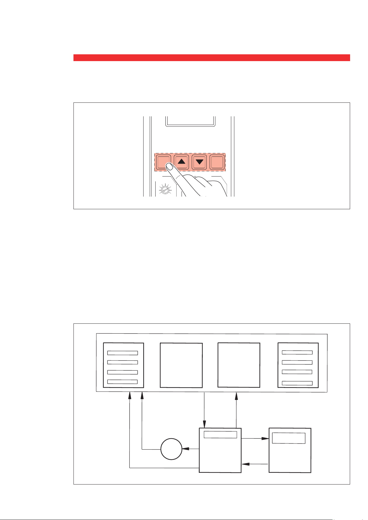
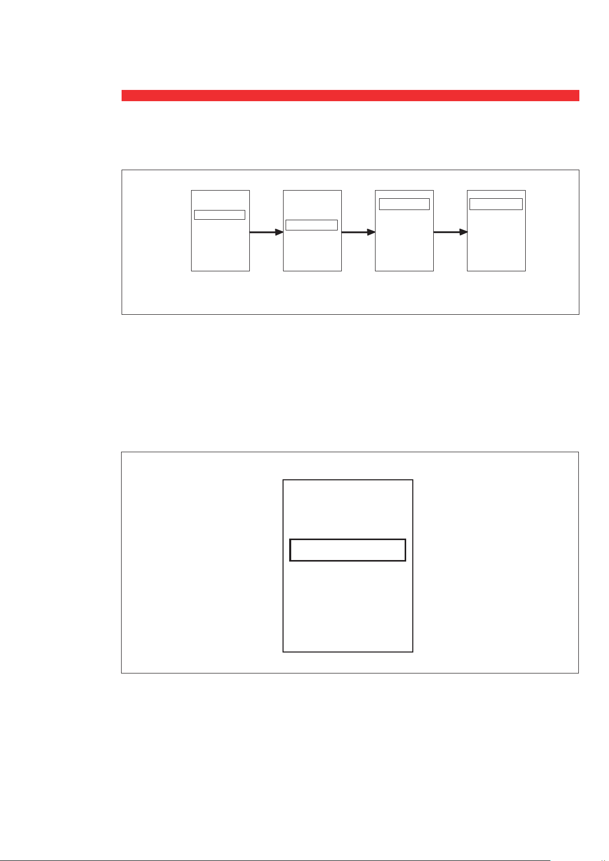
5. Visualisation et utilisation des menus
Appuyer pour afficher l’écran
OK C
lg
0.6
0.5
0.4
0.3
0.2
tg
0.7
0.5
0.8
1 0.1
0.2
0.1
OFF
test
1
1
0.5
0.2
Pour naviguer dans les menus,utiliser les boutons OK.
▲ et ▼. Il est possible de visualiser 3 types de pages.
• Page par défaut : montre l’état du disjoncteur dans toutes les utilisations admises (ferménormal, fermé-alarme déclenché, ouvert). Ces
indications s’affiche à chaque fois que l’unité de
protection est allumée et elle sont automatiquement mises à jour dans le cas où.à l'issue
d’une durée préétablie (programmée sur T1=10
seconds), aucun des 4 boutons de navigation n'ait
utlisé. Depuis cette page, il est possible d'accéder
à la page Menu en appuyant sur le bouton OK.
• Pages menu : il s'agit des pages actives
fermé-normal fermé-alarme ouve
N: 1550A
L1: 1600A
L2: 1605A
L3:
1598A
alarme
surchauffe
T >75°C
durant l'utilisation du menu. Il est possible de
quitter des pages de sous-menus permettant le
réglage d'un paramètre (exemple: réglage de la
luminosité) de trois manière différentes:
(1) appuyer sur le bouton OK : retour au
niveau supérieut avec sauvegarde du nouveau
paramètre.
(2) appuyer sur le bouton C : retour au
niveau supérieut sans sauvegarde du nouveau
paramètre.
(3) Au bout de la durée T1: retour à la
page principale sans sauvegarde du nouveau
paramètre.
déclenché
déclenchement de la
phase de surcharge L1
5.42 S
9648
n
I =
I1=
I2=
I3=
1586A
9648A
1610A
1598A
L1: 0
L2: 0
L3:
N:
0 A
0 A
OK C
t > 20m
C
protections
état modules
param.
système
archives
OK
protections
courant
C
11
Page 12

Unité de Protection
6. Page par défaut
Comme indiqué ci-après, l’écran est constitué de huit lignes pour afficher les contenus.
Le disjoncteur peut se trouver dans quatre types d’état :
1. Disjoncteur en fermé-normal : (aucune pré-alarme ni signal d’alarme)
le contrôleur affiche :
L1:
L2:
L3:
N:
Dans cette condition (disjoncteur fermé et absence d’alarme), il est possible d’accéder à la page
principale en appuyant sur le bouton OK.
L1, L2 et L3 sont toujours mesurés ; seul le Neutre est présent.
1600A
1605A
1598A
550A
12
Page 13

Unité de Protection
alarme
surchauffe
T >75°C
2. Disjoncteur fermé-alarme :
quand le disjoncteur est en condition d’alarme, l’écran de l’unité de protection affiche :
alarme
surchauffe
T >75°C
Dans cette condition, il est possible d’accéder à la page principale en appuyant sur le bouton OK.
3. Disjoncteur déclenché :
l’écran affiche :
Défaut thermique L1
5.42 S
9648 A
n
I =
I1=
I2=
I3=
La première ligne et la deuxième ligne de l’écran affiche la page d’erreur.
Si plusieurs erreurs sont présentes ou si la même erreur est présente sur plusieurs phases, il est possible
d'accéder à la page principale en appuyant sur le bouton OK et de contrôler les données enregistrées.
1586A
9648A
1610A
1598A
13
Page 14

Unité de Protection
4. Disjoncteur ouvert :
l’écran affiche :
L1: 0 A
L2: 0 A
L3: 0 A
N: 0 A
Depuis cette page, il est possible d’accéder à la page principale en appuyant sur le bouton OK.
7. Visualisation des courants de réglages
Chaque courant peut être visualisé de 2 manières différentes:sous la forme d'un histogramme ou d'une
valeur numérique (tous deux calculés avec la même précision):
Le nombre maximal de chiffres,pour la valeur numérique,est 4,donc pour les valeurs inférieures à
9999, le courant est exprimé en Ampères,tandis que pour les valeurs comprises entre 10000 et
99999, les courants sont exprimés en kiloAmpères, avec une approximation à la plus proche valeur
décimale inférieure :
• Exemple 1 : 1 450 Ampères dans ce cas l'affichage indiquera 1 450 A
• Exemple 2 : 1 2541 Ampères dans ce cas l'affichage indiquera 12.5 KA
L’histogramme de courant peut afficher des valeurs supérieures ou égales au seuil 1,2*I (A) ; le seuil
l est le seuil de courant pour la protection thermique (Ir) ; si le courant mesuré est supérieur à la valeur
maximum, l’histogramme complet s’affiche (soit équivalent à un seuil de 120%). Chaque histogramme
contient un maximum de 48 unités graphiques, chacun correspondant à 2% du montant total,avec une
approximation à la valeur décimale inférieure la plus proche :
• Exemple : Ir = 1000A chaque point graphique correspond à 20A.Si,dans ce cas, I1 = 18A et I2
= 565A, sur l'histogramme, il n'y aura pas de point graphique pour I1 et 28 points graphiques pour I2.
14
Page 15
Unité de Protection
A
A
A
A
A
niveau 3
état
alarmes mesures
présentes
courant
température
instant.
I1= 0
A
protections
état modules
param. système
archives
niveau 2niveau 1
{
{
{
{
I2= 0
A
I3= 0
A
I = 0
A
Ig= 0
A
N
OK OK OK
niveau 4
8. Pages menu :
protections
état modules
param. système
archives
VISUALISATION :
L’écran affiche 4 niveaux de données imbriquées,il est possible de les modifier à l'aide des toudres ▲
et ▼; l’indication encadrée signifie la présence d’une autre page : pour accéder au sous-niveau,
appuyer sur le bouton OK.
RÉGLAGES :
Si la page permet de régler un paramètre (exemple : réglage séquence phase, réglage adresse
Modbus, etc.), il est possible de modifier la valeur à l’aide des boutons ▲et ▼ , jusqu’à ce que le
cadre s’affiche en gras pour accéder à l’état de réglage en appuyant sur le bouton OK. Les nouveaux
réglages sont actifs uniquement à condition d’être confirmés en appuyant sur le bouton OK.
état
alarmes mesures
présentes
OK OK OK
{
niveau 2niveau 1
{
courant
température
niveau 3
{
instant.
I1= 0
I2= 0
I3= 0
I = 0
N
Ig= 0
niveau 4
{
Adresse
Modbus com.
3
Vitesse
9.6k
15
Page 16
Unité de Protection
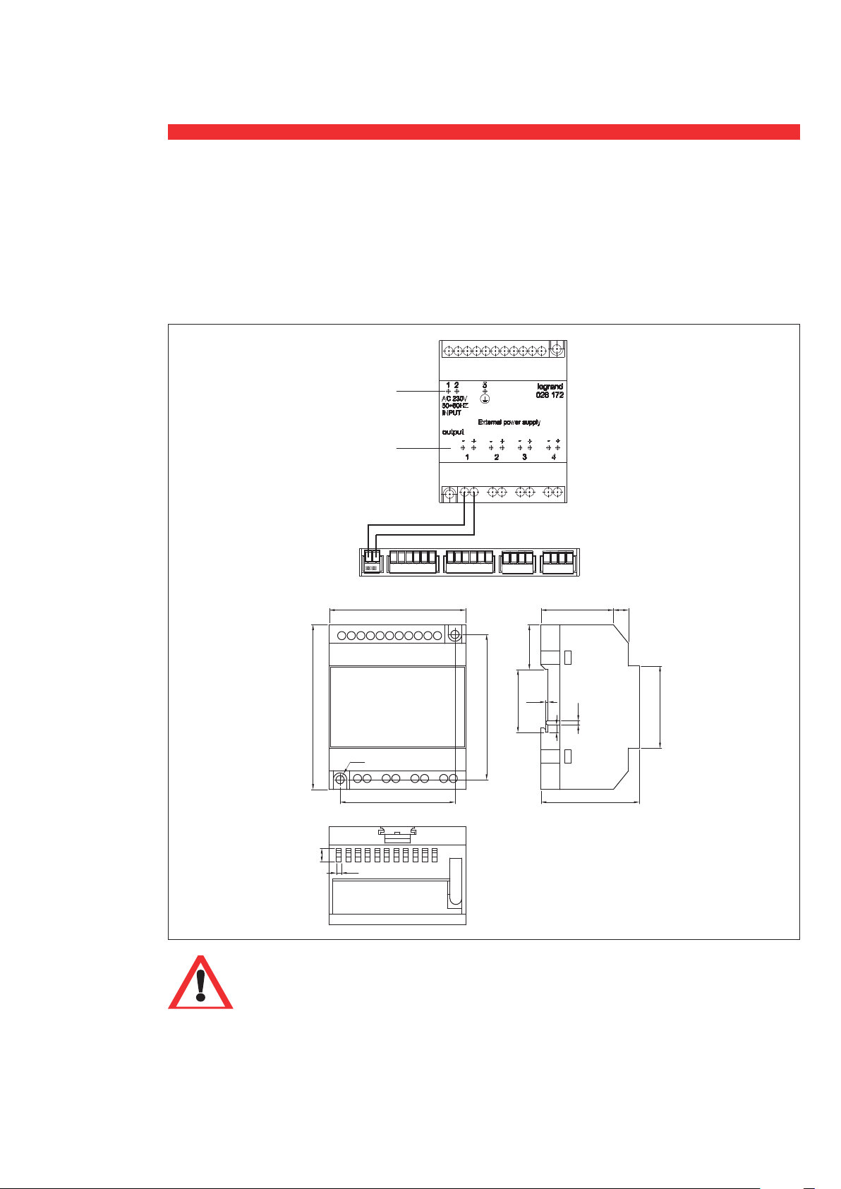
9. Accessoires
0 281 72 Module d alimentation externe
L'appareil dispose d'une entrée 230V AC et une consommation électrique maximale de 25 VA.
L'alimentation dispose de 4 sorties indépendantes afin de raccorder 4 unités de protection.
Ce produit prévoit 2 types d’installation en adoptant des rails standard de 35 mm ou une fixation
directe. Ci-dessous sortie et dimensions d’installation.
ENTRÉE
SORTIE
72/144
24.5
1.5
90
4.5
60.5/121
7.5
2.5
35.5
82
39 8
4
2.5
45
53
16
Note:
DMX3 1600 seul: Pour garantir un bon fonctionnement de l'unité de protection, l'alimentation
externe est obligatoire.
Deux options sont possibles:
1. par alimentation externe auxiliaire (LG-028172)
2. par alimentation directe 110-230Vac (bornes PU1-PU2)
*pour alimentation directe, prevoir une protection à fusible (50mA type gR)
Page 17

Unité de Protection
0 281 70 (Assemblé en usine)
Modbus RS485 option communication
Assemblée en usine, cette option permet de brancher le disjoncteur à un système de supervision
MODBUS RS485.
0 281 99 (Assemblé en usine)
Contacts module réglable
Ce module est un accessoire utilisé pour gérer d’autres dispositifs externes de signal/contrôle. Il doit
être relié à l’unité de protection qui permet son réglage et doit être branché aux bornes sur la partie
supérieure du disjoncteur.
Activation:
Les sorties programmables peuvent être activée avec le changement de réglages d'unité de protection
MP4,dans le menu de PU comme spécifié ci-dessous:
Etape 1: Réglage ➔ Relais ➔ Programmation ➔ choisir Relais 1 ou 2 dans la liste de
sorties ➔ choisir les options dans Ia liste de fonctionnes
Etape 2: Réglage ➔ Relais ➔ Fonction de contact ➔ choisir Relais 1 ou 2 dans la liste de
sorties ➔ choisir les options (NO/NC - Stable/temporisé) dans la liste de fonctionnes.
Options
NO Niveau
NC Niveau
NO temps (1÷360s)
NC temps (1÷360s)
Characteristiques techniques:
Tension nominale Vn (Vac) 230V 5A MAX
(Vdc) 110V 0.5A MAX
17
Page 18

Unité de Protection
0 281 71 pour DMX3 1600
6 696 05 pour DMX-SP 2500
Transformateur de courant externe pour erreur terre et protection neutre
Il est possible de l’utiliser avec des disjoncteurs à 3 pôles et il est installé sur le neutre dans les cas
suivants :
- protection neutre (avec toutes les versions de l'unité de protection);
- protection erreur terre (seulement avec version 0 281 66 et 0 281 68).
18
Page 19

Unité de Protection
10. Sélectivité logique
La sélectivité logique n'est pas incluse dans les versions des unités de contôle réf.0 281 67/0 281 68.
Pour les indications générales et les exigences concernant la fonction Sélectivité Logique, reqortez-vous
au Guide de Sélectivité Logique standard.
Bornes de raccordement
Veuillez vous référer au manuel d'installation du disjoncteur.
Activation
Les connexions d'entrée /sortie pour la sélectivité logique peuvent être activées au moyen de la modification des paramètres de l'unité de protection en naviguant dans le menu, comme spécifié ci-dessous :
Réglage ➔ Relais ➔ Programmation ➔
ner ON dans la liste des fonctions (non requis pour le dernier niveau de sélectivité en aval - D)
Réglage ➔ Relais ➔ Programmation ➔
tionner
Connexions et alimentation:
Veuillez noter que l'unité de protection doit toujours être alimentée par un module externe spécifique
réf. 0 281 72 pour le bon fonctionnement de la sélectivité logique.
Par ailleurs,l'entrée de la sélectivité logique (SEL - IN) doit également être alimentée sur ses bornes par
une tension de 24Vdc. Dans le détail,la polarité positive de l'alimentation + (24V) doit être connectée
à la borne H11.
Cette alimentation peut être fournie par le même module ref. 0 281 72 qui alimente l'unité de protection.
En revanche,la sortie de la sélectivité logique (SEL - OUT) ne nécessite pas d'alimentation supplémentaire.
ON
dans la liste des fonctions (requis pour tous les niveaux de sélectivité A/B/C/D)
choisir
choisir
SEL IN
SEL OUT
dans la liste des contacts ➔ sélection-
dans la liste des contacts ➔ sélec-
19
Page 20

Unité de Protection
2# 3# 4#
1#
DO
DI
DO
DI
DO
DI
DO
DI
DC 24V
Schéma de cataloque:
DO
2# 3# 4#
DI
1#
DO
DI
DO
DI
DC 24V
DO
DI
Ci-dessous,un résumé des principaux niveaux de sélectivité (A/C/D) et les prescriptions spécifiques
relatives afin de communiquer correctement.
A
IN
C
OUT
IN
D
L max = 30 m L max = 30 m
OUT
DMX³
2500
1600
DMX³
1600
DMX³
DPX 1600
DPX 630
DPX 250
DPX³
OUT
SEL
IN
OUT
SEL
IN
OUT
SEL
IN
+
ON
ON
+
DMX³
6300
4000
DMX³
4000
2500
1600
DMX³
1600
OUT
SEL
IN
OUT
SEL
IN
OUT
SEL
IN
+
ON
+
OFF
DMX³
1600
C
DMX³
DPX 1600
DPX 630
DPX 250
DPX³
D
DPX 630
DPX 250
DPX³
OUT
SEL
IN
OUT
SEL
IN
OUT
SEL
IN
+
+
OFF
ON
20
Remarque:
Il n'y a aucun risque ni aucune restriction quant à l'utilisation de la sélectivité logique des DMX3 1600/
DMX-SP avec des aurtes dispositifs DPX/DPX3/DMX3 (où l'alimentation 24Vdc n'est pas nécessaire).
Page 21

Unité de Protection
A
A
A
A
k
A
A
11. Navigation menu
O
L1:
OA
L2:
O
L3:
N: O
OK
1/6 1/1
protections
état modules
param.
système
archives
(protections
courant)
OK OK OK
1/5
(protections
courant)
longue durée
courte durée
instant.
longue durée
IR= 1600
(100.0%In )
modifier avec commande
suite page 22
état 2/6
2/5
(protections
courant)
longue durée
courte durée
instant.
3/5
(protections
courant)
longue durée
courte durée
instant.
4/5
protec. neutre
protec. terre
OK
OK
OK
longue durée
TR= C3
( 20s @ 6.0IR
mém-therm.
)
on
t=
I=1280 0
( 8.0× IR
T=0 .5s
instant.
I=24000
( )
15.0×In
protec. neutre
OFF
modifier avec commande
modifier avec commande
)
modifier avec commande
modifier avec commande
5/5
OK
protec. terre
OFF
modifier avec commande
protec. neutre
protec. terre
seulement pour les versions avec protection de terre
21
Page 22

Unité de Protection
A
A
A
A
A
2/6 1/3
état
protections
modules
param. système
archives
OK OK
état
alarmes
mesures
présentes
2/3
état
alarmes mesures
présentes
OK
état
fermé
alarmes présentes
aucune alarme
suite page 23
modules 3/6
3/3 1/2
état alarmes
présentes
mesures
OK OK
courant
température
température
courants
2/2
OK
instant.
I1= 0
I2= 0
I3= 0
I = 0
N
Ig= 0
température
T=3 5°C
22
Page 23

Unité de Protection
3/6
protections
état
modules
param. système
archives
suite page 24
paramètres
système 4/6
1/2
réglages relai
réglage com.
OK OK
2/2
com. réglage
réglages relai
OK OK
Adresse
Modbus com.
3
vitesse
9.6 k
réglage relai
réglages
fonc. mode
fonct. état relai
réglage relai
réglages
fonc. mode
fonct. état relai
réglage relai
réglages
fonc. mode
fonct. état relai
OK
Modifier/sauvegarder
adresse de communication
vitesse detransmission
1/3
2/3
OK
3/3
OK
func. seréglages
fonc. relai 1
alarme-génér.
mode fonct.
relai 1
niveau N / O
relai 1
relai 2
relai 3
SEL-IN
OK
modifier/sauvegarder le
réglage de la fonction
OK
modifier/sauvegarder le
mode de travail
Options
Hors service
Alarme
Défauts de declench
Surcharge de l'alarme
Défaut de surcharge
Défaut magnetique
Défaut instantané
Défaut de terre
Défaut du neutre
Fermé
Ouvert
Fix. Instantané Défauts
Surchauffe >75°C
23
Page 24

Unité de Protection
4/6
protections
état
modules
param. système
archives
1/4
disjoncteur
protocole com.
date / heure
OK OK
langue
2/4
disjoncteur
protocole
date / heure
langue
OK
3/4
disjoncteur
protocole com.
date / heure
langue
OK
courant assigné
1600A
Nb de pôles
4P
séquence phase
L1, L2, L3, N
protocole com.
Modbus
date
2015/06/08
heure
14:30 :30
OK
régler date et heure
suite page 25
archives 5/6
4/4
disjoncteur
protocole com.
date /heure
langue
langue
Anglais
OK OK OK
langue
Anglais
langue
Français
sauvegarder
24
Page 25

Unité de Protection
5/6
protections
état modules
param.
système
archives
historique
positions
historique
erreurs
historique
alarmes
historique
positions
historique
erreurs
historique
alarmes
historique
positions
historique
erreurs
historique
alarmes
1/3
2/3
3/3
OK
OK
OK
historique
positions
ferm. locale
2015/06/08
ouv. erreur
2015/06/08
ferm. locale
2015/06/08
historique erreurs
déclench.
surcharge
2015/06/08
déclench.
surcharge
2015/06/08
déclench.
surcharge
2015/06/08
historique
alarme
surchauffe
pré-alarme
2015/06/08
pré-alarme
surchauffe
2015/06/08
pré-alarme
surchauffe
10 fois historique
de position
10 fois historique
de déclenchement
10 fois historique
l’historique des alarmes
information
6/6
OK
FW version
P1605, T31H
3
DMX
25
Page 26

Unité de Protection
12. Structure des menus
MENU NIVEAU 1 MENU NIVEAU 2 MENU NIVEAU 3 MENU NIVEAU 4
longue durée
courte durée
protections protection courant
état
état
modules
paramètres système
archives
information FW version
alarmes présentes
mesures
réglage com.
réglages relai
disjoncteur courant assigné - Nb pôles - séquence phase
protocole com. MODBUS
date / heure date - heure
langue
historique positions
historique erreurs
historique alarmes
instantané
protec. neutre
protec. terre
courants instant.
température
Adresse Modbus
com.
vitesse
relai 1
réglage fonct
NO/NF/NO impulsion/NF impulsion
mode fonct.
état relai NO: O, NF: I
Anglais
Autres langues
NO/NF/NO impulsion/NF impulsion
NO/NF/NO impulsion/NF impulsion
relai 2
SEL-OUT
SEL-IN
NO/NF
26
Page 27

Protection unit
References 0 281 64/65/66/67/68
June 17
LE08438AB
Page 28

Page 29

Contents
1. Identification and factory setting ..... 30
2. Setting protection levels ............. 32
3. Signaling of protection unit state ........ 35
4. Test button........................ 36
5. Visualization and use of menus ....... 37
6. Default page ...................... 38
7. Setting of current visualization ........ 40
8. Menu pages ...................... 41
9. Accessories ....................... 42
10. Logical selectivity ................... 45
11 . Menu navigation ................... 47
12. Menu structure .................... 52
Version FW: P1611, TXXH GLXX DMX
3
29
Page 30

Protection unit
1. Identification and factory setting
0 281 64
LCD TYPE WITH LI
PROTECTION
factory setting
Ii=Icw
Isd=10 x Ir fix
tsd=0.1s fix
Ir=(0.9+0.1) xIn
tr=5s (MEM=OFF)
N=100%
0 281 65
LCD TYPE WITH LSI
PROTECTION
factory setting
Ii=Icw
Isd=10 x Ir
tsd=0.1s (t=const)
Ir=(0.9+0.1) xIn
tr=5s (MEM=OFF)
N=100%
0 281 66
LCD TYPE WITH LSIg
PROTECTION
factory setting
Ig=0.2×In
tg=0.1 @ t=const, li=Icw
Isd=10 x Ir
tsd=0.1s (t=const)
Ir=(0.9+0.1) xIn
tr=5s (MEM=OFF)
N=100%
MAN
AUT
0 281 64
AUT
MAN
t
OK C
lsd
li
4
5
6810
3
2.5
6
12
4
2
15
3
2
lr
0.7
0.6
0.5
0.4
ON
10
lcw
1.5
x
x
ln
lr
0.08
0.8
0.06
0.9
0.1
0.04
0.02
+
0.00
x
ln
N
100%
x
lr
50%
l>.90
OFF
l>1.05
MAN
AUT
0 281 67
test
tsd
0.5
8
0.2
0.1
tr
20
10
5
0 281 65
AUT
MAN
0 281 68
t
OK C
lg
tg
test
1
0.6
1
0.5
0.7
0.5
0.5
0.8
0.4
0.3
2
l
t=k@12lr
1
1
0.5
0.2
0.1
s
MEM-OFF
30
20
30
10
5
@6I
r
s
0.2
li
6810
4
3
2
lr
0.7
0.6
0.5
0.4
ON
1 0.1
OFF
12
15
lcw
x
ln
0.8
0.9
x
lr
l>.90
l>1.05
MAN
0.2
0.2
0.1
2
tsd
lsd
l
t=k@12lr
1
4
5
1
0.5
3
2.5
6
0.5
0.2
8
2
1.5
0.06
0.04
0.02
+
0.00
N
100%
50%
OFF
0.1
0.2
10
0.1
x
lr
s
tr
MEM-OFF
0.08
30
20
30
0.1
20
10
10
5
5
@6I
r
s
x
ln
AUT
0 281 66
30
0 281 67
BASIC TYPE LSI PROTECTION
factory setting
Ii=Icw
Isd=10 x Ir
tsd=0.1s (t=const)
Ir=(0.9+0.1) xIn
tr=5s (MEM=OFF)
N=100%
0 281 68
BASIC TYPE WITH LSIg
PROTECTION
factory setting
Ig=0.2×In
tg=0.1 @ t=const, li=Icw
Isd=10 x Ir
tsd=0.1s (t=const)
Ir=(0.9+0.1) xIn
tr=5s (MEM=OFF)
N=100%
"MEM OFF" = Thermal memory
deactivated
lg
test
li
6810
12
4
15
3
lcw
2
x
ln
tr
lr
0.8
0.9
0.7
0.6
0.5
+
0.4
x
lr
ON
l>.90
l>1.05
MEM-OFF
0.08
30
20
0.06
30
0.1
20
0.04
0.02
0.00
N
100%
50%
OFF
10
10
5
5
@6I
r
s
x
ln
li
6810
4
3
2
x
lr
0.8
0.9
0.7
0.6
0.5
0.4
ON
l>.90
l>1.05
test
2
tsd
lsd
l
t=k@12lr
1
4
5
1
0.5
3
2.5
6
0.5
12
2
15
lcw
1.5
ln
0.06
0.04
0.02
+
0.00
N
100%
x
lr
50%
OFF
0.2
8
0.1
0.2
10
0.1
x
lr
s
tr
MEM-OFF
0.08
30
20
30
0.1
20
10
10
5
5
@6I
r
s
x
ln
0.4
0.3
0.2
li
lr
0.6
0.5
0.4
0.5
4
3
2
0.7
ON
6810
0.6
0.7
x
0.8
0.9
l>.90
l>1.05
tg
0.5
0.8
1 0.1
0.2
0.1
OFF
lsd
2.5
12
2
15
lcw
1.5
ln
0.06
0.04
0.02
+
0.00
N
100%
x
lr
50%
OFF
test
1
1
0.5
0.2
2
tsd
l
t=k@12lr
1
4
5
1
0.5
3
6
0.5
0.2
8
0.1
0.2
10
0.1
x
lr
s
tr
MEM-OFF
0.08
30
20
30
0.1
20
10
10
5
5
@6I
r
s
x
ln
Page 31

Protection unit
RESET PIN
MAN
AUT
0 281 66
LCD INTERFACE DISPLAY
TRIP LED INDICATION
GROUND FAULT
PROTECTION
LED INDICATION
OK C
lg
0.6
0.5
0.4
0.3
0.2
li
6810
4
3
2
lr
0.8
0.7
0.6
0.5
0.4
ON
tg
0.7
0.5
0.8
0.2
1 0.1
0.1
OFF
lsd
2.5
12
2
15
lcw
1.5
x
ln
0.06
0.9
0.04
0.02
+
0.00
N
100%
x
lr
50%
l>.90
OFF
l>1.05
1
1
0.5
0.2
4
5
3
6
8
10
x
lr
0.08
0.1
x
ln
0.2
10
test
tsd
0.5
0.1
tr
20
1
30
5
2
l
t=k@12lr
1
0.5
MEM-OFF
30
20
@6I
r
MENU NAVIGATION
BUTTONS
TRIP TEST BUTTON
INSTANTANEOUS
AND SHORT TIME
0.2
0.1
s
PROTECTION
LONG TIME
10
5
s
PROTECTION
USB
NEUTRAL PROTECTION
31
Page 32

Protection unit
2. Setting protection levels
Set the levels of protection by turning rotary switches with a flat screwdriver.
32
Page 33

0 281 66
OK C
0 281 66
MAN
AUT
@6I
0.3
0.2
0.4
0.5
0.6
0.7
0.8
1 0.1
0.2
0.5
1
0.1
0.2
0.5
1
lg
tg
test
2
3
4
6810
12
15
lcw
li
x
ln
1.5
2.5
2
3
4
5
6
8
10
x
lr
lsd
OFF
0.1
0.2
0.5
1
1
0.5
0.2
0.1
s
tsd
l
2
t=k@12lr
lr
0.4
0.5
0.6
0.7
0.8
0.9
+
0.00
0.02
0.04
0.06
0.08
0.1
5
10
20
30
30
20
10
5
MEM-OFF
s
r
tr
N
100%
50%
OFF
x
ln
ON
x
lr
l>.90
l>1.05
@6I
0 281 66
0.3
0.2
0.4
0.5
0.6
0.7
0.8
1 0.1
0.2
0.5
1
0.1
0.2
0.5
1
lg
tg
test
2
3
4
6810
12
15
lcw
li
x
ln
1.5
2.5
2
3
4
5
6
8
10
x
lr
lsd
OFF
0.1
0.2
0.5
1
1
0.5
0.2
0.1
s
tsd
l
2
t=k@12lr
lr
0.4
0.5
0.6
0.7
0.8
0.9
+
0.00
0.02
0.04
0.06
0.08
0.1
5
10
20
30
30
20
10
5
MEM-OFF
s
r
tr
N
100%
50%
OFF
x
ln
ON
x
lr
l>.90
l>1.05
OK C
0 281 66
MAN
AUT
OK C
0 281 66
MAN
AUT
OK C
@6I
0.3
0.2
0.4
0.5
0.6
0.7
0.8
1 0.1
0.2
0.5
1
0.1
0.2
0.5
1
lg
tg
test
2
3
4
6810
12
15
lcw
li
x
ln
1.5
2.5
2
3
4
5
6
8
10
x
lr
lsd
OFF
0.1
0.2
0.5
1
1
0.5
0.2
0.1
s
tsd
l
2
t=k@12lr
lr
0.4
0.5
0.6
0.7
0.8
0.9
+
0.00
0.02
0.04
0.06
0.08
0.1
5
10
20
30
30
20
10
5
MEM-OFF
s
r
tr
N
100%
50%
OFF
x
ln
ON
x
lr
l>.90
l>1.05
0 281 66
OK C
0 281 66
MAN
AUT
OK C
MAN
AUT
@6I
0.3
0.2
0.4
0.5
0.6
0.7
0.8
1 0.1
0.2
0.5
1
0.1
0.2
0.5
1
lg
tg
test
2
3
4
6810
12
15
lcw
li
x
ln
1.5
2.5
2
3
4
5
6
8
10
x
lr
lsd
OFF
0.1
0.2
0.5
1
1
0.5
0.2
0.1
s
tsd
l
2
t=k@12lr
lr
0.4
0.5
0.6
0.7
0.8
0.9
+
0.00
0.02
0.04
0.06
0.08
0.1
5
10
20
30
30
20
10
5
MEM-OFF
s
r
tr
N
100%
50%
OFF
x
ln
ON
x
lr
l>.90
l>1.05
@6I
0 281 66
0.3
0.2
0.4
0.5
0.6
0.7
0.8
1 0.1
0.2
0.5
1
0.1
0.2
0.5
1
lg
tg
test
2
3
4
6810
12
15
lcw
li
x
ln
1.5
2.5
2
3
4
5
6
8
10
x
lr
lsd
OFF
0.1
0.2
0.5
1
1
0.5
0.2
0.1
s
tsd
l
2
t=k@12lr
lr
0.4
0.5
0.6
0.7
0.8
0.9
+
0.00
0.02
0.04
0.06
0.08
0.1
5
10
20
30
30
20
10
5
MEM-OFF
s
r
tr
N
100%
50%
OFF
x
ln
ON
x
lr
l>.90
l>1.05
OK C
@6I
0 281 66
0.3
0.2
0.4
0.5
0.6
0.7
0.8
1 0.1
0.2
0.5
1
0.1
0.2
0.5
1
lg
tg
test
2
3
4
6
8
10
12
15
lcw
li
x
ln
1.5
2.5
2
3
4
5
6
8
10
x
lr
lsd
OFF
0.1
0.2
0.5
1
1
0.5
0.2
0.1
s
tsd
l
2
t=k@12lr
lr
0.4
0.5
0.6
0.7
0.8
0.9
+
0.00
0.02
0.04
0.06
0.08
0.1
5
10
20
30
30
20
10
5
MEM-OFF
s
r
tr
N
100%
50%
OFF
x
ln
MAN
AUT
ON
x
lr
l>.90
l>1.05
OK C
0 281 66
MAN
AUT
OK C
Protection unit
Ground fault protection
(only for item 0 281 66
and 0 281 68)
Setting of current (9 steps)
Ig=0.2-0.3-0.4-0.5-0.6-0.7-0.8-1
lg
0.4
0.3
0.2
li
×In-OFF
lr
Setting of time delay (@12×Ig)
(4+4 steps)
0.6
0.5
0.4
tg=0.1-0.2-0.5-1s(t=const)
tg=1-0.5-0.2-0.1s(I t=const)
Long time protection
Setting of current (2x6 steps)
Ir=0,4÷1×In
With 2 switches
(0,4÷0,9, steps of 0,1
0,0÷0,1, steps of 0,02)
Example:
Ir =(0.4+0.06)×In= 0.46 In
Setting of time delay (@6Ir)
(4+4 steps)
tr=5-10-20-30s (MEM ON)
tr=30-20-10-5s (MEM OFF)
MEM OFF = thermal memory off
MEM ON = thermal memory on
Short circuit protection
Setting of current (9 steps)
Isd=1.5-2-2.5-3-4-5-6-8-10xIr
If Ii<Isd, then instantaneous setting
prevails against the magnetic one.
lg
0.4
0.3
0.2
li
3
lr
0.6
0.5
0.4
lg
0.4
0.3
0.2
li
3
lr
0.6
0.5
0.4
lg
0.4
0.3
0.2
li
3
lr
0.6
0.5
0.4
*“Fixed instantaneous short
time protection=Isf=Icw@415V”
3
ON
0.5
4
2
0.7
ON
0.5
4
2
0.7
ON
0.5
4
2
0.7
0.5
4
2
0.7
ON
0.6
6810
0.8
0.6
6810
0.8
0.6
6
0.8
0.6
6810
0.8
0.7
0.8
1 0.1
OFF
12
15
lcw
x
ln
0.9
+
x
lr
l>.90
l>1.05
0.7
0.8
1 0.1
OFF
12
15
lcw
x
ln
0.9
+
x
lr
l>.90
l>1.05
0.7
0.8
1 0.1
OFF
8
10
12
15
lcw
x
ln
0.9
+
x
lr
l>.90
l>1.05
0.7
0.8
1 0.1
OFF
12
15
lcw
x
ln
0.9
+
x
lr
l>.90
l>1.05
tg
test
1
1
0.5
0.5
0.2
0.2
0.1
2
tsd
lsd
2.5
2
1.5
0.06
0.04
0.02
0.00
N
100%
50%
OFF
tg
0.5
0.2
0.1
lsd
2.5
2
1.5
0.06
0.04
0.02
0.00
N
100%
50%
OFF
tg
0.5
0.2
0.1
lsd
2.5
2
1.5
0.06
0.04
0.02
0.00
N
100%
50%
OFF
tg
0.5
0.2
0.1
lsd
2.5
2
1.5
0.06
0.04
0.02
0.00
N
100%
50%
OFF
l
t=k@12lr
1
4
5
1
3
0.08
1
1
4
3
0.08
1
1
4
3
0.08
1
1
4
3
0.08
0.5
6
0.5
0.2
8
0.1
0.2
10
0.1
x
lr
s
tr
MEM-OFF
30
20
30
0.1
20
10
10
5
5
@6I
r
x
0.5
5
x
0.1
x
0.5
5
x
0.1
x
0.5
5
x
0.1
x
s
ln
test
0.2
2
tsd
l
t=k@12lr
1
1
0.5
6
0.5
0.2
8
0.1
0.2
10
0.1
lr
s
tr
MEM-OFF
30
20
30
20
10
10
5
5
@6I
r
s
ln
test
0.2
2
tsd
l
t=k@12lr
1
1
0.5
6
0.5
0.2
8
0.1
0.2
10
0.1
lr
s
tr
MEM-OFF
30
20
30
20
10
10
5
5
@6I
r
s
ln
test
0.2
2
tsd
l
t=k@12lr
1
1
0.5
6
0.5
0.2
8
0.1
0.2
10
0.1
lr
s
tr
MEM-OFF
30
20
30
20
10
10
5
5
@6I
r
s
ln
33
Page 34

OK C
0 281 66
MAN
AUT
@6I
0.3
0.2
0.4
0.5
0.6
0.7
0.8
1 0.1
0.2
0.5
1
0.1
0.2
0.5
1
lg
tg
test
2
3
4
6810
12
15
lcw
li
x
ln
1.5
2.5
2
3
4
5
6
8
10
x
lr
lsd
OFF
0.1
0.2
0.5
1
1
0.5
0.2
0.1
s
tsd
l
2
t=k@12lr
lr
0.4
0.5
0.6
0.7
0.8
0.9
+
0.00
0.02
0.04
0.06
0.08
0.1
5
10
20
30
30
20
10
5
MEM-OFF
s
r
tr
N
100%
50%
OFF
x
ln
ON
x
lr
l>.90
l>1.05
OK C
0 281 66
MAN
AUT
OK C
0 281 66
MAN
AUT
@6I
0.3
0.2
0.4
0.5
0.6
0.7
0.8
1 0.1
0.2
0.5
1
0.1
0.2
0.5
1
lg
tg
test
2
3
4
6810
12
15
lcw
li
x
ln
1.5
2.5
2
3
4
5
6
8
10
x
lr
lsd
OFF
0.1
0.2
0.5
1
1
0.5
0.2
0.1
s
tsd
l
2
t=k@12lr
lr
0.4
0.5
0.6
0.7
0.8
0.9
+
0.00
0.02
0.04
0.06
0.08
0.1
5
10
20
30
30
20
10
5
MEM-OFF
s
r
tr
N
100%
50%
OFF
x
ln
ON
x
lr
l>.90
l>1.05
OK C
@6I
0 281 66
0.3
0.2
0.4
0.5
0.6
0.7
0.8
1 0.1
0.2
0.5
1
0.1
0.2
0.5
1
lg
tg
test
2
3
4
6
8
10
12
15
lcw
li
x
ln
1.5
2.5
2
3
4
5
6
8
10
x
lr
lsd
OFF
0.1
0.2
0.5
1
1
0.5
0.2
0.1
s
tsd
l
2
t=k@12lr
lr
0.4
0.5
0.6
0.7
0.8
0.9
+
0.00
0.02
0.04
0.06
0.08
0.1
5
10
20
30
30
20
10
5
MEM-OFF
s
r
tr
N
100%
50%
OFF
x
ln
MAN
AUT
ON
x
lr
l>.90
l>1.05
OK C
0 281 66
MAN
AUT
OK C
Protection unit
Setting of time delay
(4+4 steps)
tsd=0.1-0.2-0.5-1s (t=const)
tsd=1-0.5-0.2-0.1s (i t=const)
lg
0.4
0.3
0.2
li
4
3
2
lr
0.6
0.5
0.4
ON
Instantaneous short circuit
protection
Setting of current (9 steps)
Ii=2-3-4-6-8-10-12-15x In or Icw
At setting "Icw", Ii protection gets
disabled increasing the selectivity.
Neutral protection
Setting of current (3 steps)
N=OFF-50%-100%
Protection against over temperature
(not adjustable) t >95°C
*“Fixed instantaneous short
time protection=Isf=Icw@ 415V”
lg
0.4
0.3
0.2
li
3
2
lr
0.6
0.5
0.4
ON
lg
0.4
0.3
0.2
li
3
2
lr
0.6
0.5
0.4
ON
0.7
4
0.7
4
0.7
0.5
0.5
0.5
0.6
6810
0.8
0.6
6
0.8
0.6
6
0.8
8
8
tg
0.7
0.5
0.8
1 0.1
0.2
0.1
OFF
lsd
2.5
12
2
15
lcw
1.5
x
ln
0.06
0.9
0.04
0.02
+
0.00
N
100%
x
lr
50%
l>.90
OFF
l>1.05
tg
0.7
0.5
0.8
1 0.1
0.2
0.1
OFF
lsd
10
2.5
12
2
15
lcw
1.5
x
ln
0.06
0.9
0.04
0.02
+
0.00
N
100%
x
lr
50%
l>.90
OFF
l>1.05
tg
0.7
0.5
0.8
1 0.1
0.2
0.1
OFF
lsd
10
2.5
12
2
15
lcw
1.5
x
ln
0.06
0.9
0.04
0.02
+
0.00
N
100%
x
lr
50%
l>.90
OFF
l>1.05
test
1
1
0.5
0.2
2
tsd
l
t=k@12lr
1
4
5
1
3
0.08
1
1
4
3
0.08
1
1
4
3
0.08
0.5
6
0.5
0.2
8
0.1
0.2
10
0.1
x
lr
s
tr
MEM-OFF
30
20
30
0.1
20
10
10
5
5
@6I
r
x
0.5
5
x
0.1
x
0.5
5
x
0.1
x
s
ln
test
0.2
2
tsd
l
t=k@12lr
1
1
0.5
6
0.5
0.2
8
0.1
0.2
10
0.1
lr
s
tr
MEM-OFF
30
20
30
20
10
10
5
5
@6I
r
s
ln
test
0.2
2
tsd
l
t=k@12lr
1
1
0.5
6
0.5
0.2
8
0.1
0.2
10
0.1
lr
s
tr
MEM-OFF
30
20
30
20
10
10
5
5
@6I
r
s
ln
NEUTRAL PROTECTION
Position Protection
OFF No protected
50% Protected at 50% Ir-Isd-Ii
100% Protected at Ir-Isd-Ii
34
Page 35

Protection unit
3
4
12
15
2.5
2
6
8
0.2
0.5
0.2
0.1
0 281 66
MAN
AUT
@6I
2
3
4
12
15
lcw
x
ln
1.5
2.5
2
6
8
10
x
lr
0.1
0.2
0.5
0.2
0.1
s
lr
0.4
0.5
0.6
0.7
0.8
0.9
+
0.00
0.02
0.04
0.06
0.08
0.1
5
10
20
30
30
20
10
5
MEM-OFF
s
r
tr
N
100%
50%
OFF
x
ln
ON
x
lr
l>.90
l>1.05
0 281 66
MAN
AUT
OK C
3. Signaling of protection unit state
lcw
2
lr
0.8
0.9
0.7
0.6
0.5
0.4
ON
l>.90
l>1.05
LED 2
LED 1
The state of Protection Unit is signaled through LED 1 and 2, according to the table:
1.5
x
ln
0.04
0.02
+
0.00
N
100%
x
lr
50%
OFF
PROTECTION
10
0.1
x
0.06
0.08
lr
tr
0.1
20
10
x
ln
30
5
MEM-OFF
30
20
@6I
r
s
10
5
s
LED1 LED2
Inactive Off Off
Active: (I 100A for DMX-SP/250A
for DMX3-1600 or supplied)
Green Off
Active: (overload prealarm I > 0.9Ir) Green Fix Red Fix
Active: (overload alarm I > 1.05Ir) Green Fix Red Flashing
Active: (over temperature alarm T >75°C) Green Flashing Red Flashing
An alarm is more important than a prealarm. The overload is more important than over temperature.
LED 3
Failure by ground fault
(only for item 0 281 66
and 0 281 68)
LED 4
Failure by short circuit/
instantaneous short circuit
LED 5
Failure by overload/
over temperature
In case of breaker tripping
the LED corresponding to
the protection that caused
the tripping remains lighted,
signalling the corresponding
fault has occured. (if external
supply is present)
LED 3
LED 4
LED 5
lg
0.6
0.5
0.4
0.3
0.2
li
8
6
4
3
2
lr
0.8
0.7
0.6
0.5
0.4
tg
0.7
0.8
OFF
10
12
15
lcw
x
ln
0.9
1
0.5
1 0.1
0.2
0.1
lsd
3
2.5
2
1.5
0.06
0.04
0.02
+
0.00
0.08
test
1
0.5
0.2
2
tsd
l
t=k@12lr
4
5
6
10
x
lr
0.1
x
ln
1
1
0.5
0.5
0.2
0.1
10
tr
20
30
5
MEM-OFF
30
20
@6I
r
0.2
0.1
s
10
5
s
8
35
Page 36

Protection unit
4. Test button
In order to verify correct functioning of circuit breaker and protection unit it’s possible to use test button.
Pushing it for more than two seconds makes the breaker trip.
Tripping sequence is:
1. push “T” button for at least two seconds;
2. all LEDs turn ON for one second (ON LED in orange, others in red);
3. circuit breaker trips and all LEDs switch off, apart ON led, that switches from orange to green.
36
Page 37

Protection unit
A
A
L1
A
5. Visualization and use of menus
OK C
Push OK to turn the display on
lg
0.6
0.5
0.4
0.3
0.2
tg
0.7
0.5
0.8
1 0.1
0.2
0.1
OFF
test
1
1
0.5
0.2
Using OK ▲▼ button to navigate through the menu.
It's possible to visualize 3 type of pages.
• Default pages: show the state of the breaker
in all the allowed states (closed-normal, closedalarm tripped, open). It's shown every time that
protection unit is turned on and it's automatically
refreshed. If after an established time, there is no
activity on the 4 navigation buttons, it returns to
home page from this page. It's possible to reach
the Menu Page only by pushing OK button.
closed-normal closed-alarm
N: 1550A
L1: 1600A
L2: 1605A
L3:
1598A
alarm
over temperature
T >75°C
• Menu pages: there are several functional
pages.
(1) push "OK" button:
store the new parameter, go to menu pages or
upper level.
(2) push "C" button:
do not save the new parameter, turn back to up
level.
(3) after 20min:
do not save the new parameter, turn back home.
tripped open
overload tripping
phase
5.42 S
9648
I =
n
I1=
I2=
I3=
1586A
9648A
1610A
1598A
L1: 0
L2: 0
L3:
N:
0 A
0 A
OK C
t > 20m
C
protections
state
modules
system para
archives
OK
current
protections
C
37
Page 38

Protection unit
6. Default page
Display screen has eight rows to show contents.
Circuit breaker has four kinds of status:
1. Circuit breaker switched ON: (no pre-alarm or alarm signal)
Protection unit display data are shown like below:
L1:
L2:
L3:
N:
In this condition (closed breaker and no alarm), it's possible to enter main page by pushing OK button.
L1,L2 and L3 are always measured; neutral only if it is present.
1600A
1605A
1598A
550A
38
Page 39

Protection unit
alarm
over temperature
T >75°C
2. Circuit breaker switched ON with an active alarm:
when circuit breaker is on alarm state, protection unit display data are shown like below:
alarm
over temperature
T >75°C
In this status, it's possible to access main page by pushing OK button.
3. Circuit breaker tripped after a fault:
protection unit display data are shown like below:
overload tripping
phase L1
5.42 S
9648 A
n
I =
I1=
I2=
I3=
The first display row shows the fault type. The second display row shows fault page. If there are several faults or same fault on different phases, it's possible to enter main page by pushing OK button
and check the records in the fault history.
1586A
9648A
1610A
1598A
39
Page 40

Protection unit
4. Circuit breaker switched OFF:
protection unit display data are shown like below:
L1: 0 A
L2: 0 A
L3: 0 A
N: 0 A
From this page is possible to reach the main page pushing one time the OK button.
7. Setting of current visualization
Every current on circuit breaker can be shown in two different ways: with an histogram or with a
numeric value (both of them calculated with the same accuracy).
Maximum number of digits, for numeric value, is 4, so for values under 9999, current is expressed in
Amperes, while for values between 10000 and 99999, currents are expressed in kiloAmperes, with
the approximation to nearest lower decimal value:
• Example 1: 1450 Amperes → in this case display will show “1450 A”
• Example 2: 12541 Amperes → in this case display will show “12.5 kA”
Histogram can show values between 0 and 1.2 x I
protection (Ir). Each histogram has up to 48 graphical points, each one corresponding to 2% of total
amount, with approximation to nearest lower decimal value:
• Example: Ir = 1000A ➔ each graphical point corresponds to 20A. If, in this case, I1 = 18A and
I2 = 565A, on histogram it will be no graphical points for I1 and 28 graphical points for I2.
threshold
, where I
is threshold current for thermal
threshold
40
Page 41

Protection unit
A
A
A
A
A
level 3 level 4
sta te
measures
currents
temperature
instant.
I1= 0
A
existing alarm
system para.
protections
sta te
modules
archives
level 2level 1
{
{
{
{
I2= 0
A
I3= 0
A
I = 0
A
Ig= 0
A
N
OK OK OK
8. Menu pages
protections
state
modules
system para.
archives
VISUALIZATION:
Display has four levels of nested data. It’s possible to navigate with ▼ and ▲ buttons. The selected
item is shown with a square around the text. To enter to the submenu, press OK button.
SETTING:
If page allows to set a parameter (ex: phase sequence, ModBus node address, etc...), value can be
changed with ▼ and ▲ buttons. To confirm, push OK button (just after this operation setting will be
operative).
{
state
existing alarm
measures
OK OK OK
{
level 2level 1
currents
temperature
{
level 3 level 4
instant.
I1= 0
I2= 0
I3= 0
I = 0
N
Ig= 0
{
Modbus
com. address
3
Speed
9.6k
41
Page 42

Protection unit
9. Accessories
0 281 72 External Auxiliary Power Supply
The device has a 230V AC input and a maximum power consumption of 25VA. The power supply has
4 independent outputs suitable to supply up to 4 protection units simultaneously. Mounting chances:
standard 35mm DIN rail or direct mounting.
Here below front face and dimensions:
INPUT
OUTPUT
72/144
24.5
1.5
90
4.5
60.5/121
7.5
2.5
35.5
82
39 8
4
2.5
45
53
42
Note:
DMX3 1600 only: For a correct working of the protection unit, it is mandatory to guarantee
the protection unit always active.
Two possible options:
1- External power supply (028172), to be connected to a safety source (UPS, for instance).
2- Direct power supply 110-230Vac 50/60Hz (terminal blocks PU1-PU2), to be connected to a
safety source or upstream line.
For direct power supply foresee a protection by fuse (50mA type gR)
Page 43

Protection unit
0 281 70 (factory assembled)
Modbus RS485 Communication option
With communication option it's possible to connect circuit breaker to a ModBus RS485 supervision system.
0 281 99 (factory assembled)
Programmable contacts option
With this option it’s possible to manage external devices for signalization and control. It’s connected
to protection unit, that allows its setup, through the terminals in the top part of the breaker.
connection terminals:
Please refer to breaker installation manual.
Activation:
The output connections for programmable contacts can be activated modlfying the protection unit
settings,navigating in menu as specified below:
Step 1: Modules ➔ Relay Settings ➔ Function Settings ➔ choose Relay 1 or 2 in contact list ➔
select the options in the function list (Please refer to ch.10. menu navigation)
Step 2: Modules ➔ Relay Settings ➔ Work Mode ➔ choose Relay 1 or 2 in contact list ➔ select
the options (NO/NC - Stable/Timed) in the function list
Options
NO level
NC level
NO pulse (1÷360s)
NC pulse (1÷360s)
Technical characteristics:
Rated operating voltage Vn (Vac): 230V 5A MAX
(Vac): 110V 0.5A MAX
43
Page 44

Protection unit
0 281 71 for DMX3 1600
6 696 05 for DMX-SP 2500
External Neutral current sensor for earth fault and neutral protection
It's possible to use it with 3 poles breakers and it's installed on the neutral busbar, in order to provide
the following protections, but guarantee the continuity on Neutral:
- neutral protection (with all the protection units versions);
- ground protection (only on versions 0 281 66 and 0 281 68).
44
Page 45

Protection unit
10. Logical selectivity
The feature logical selectivity is not supported by PU versions ref. 0 281 67 / 0 281 68.
For the General indications and requirements about the function Logical Selectivity refer to standard
Logical Selectivity Guide.
Connection terminals:
Please refer to breaker installation manual.
Activation:
The input/output connections for logical selectivity can be activated by modifying the protection unit
settings navigating in menu as specified below:
Setting
function list (not required for the last downstream selectivity level - D)
Setting
the function list (required for all selectivity levels - A/B/C/D)
Wiring and Supply:
Please remind the protection unit always needs to be supplied by a specific external module
ref. 0 281 72 in order to provide a correct working of logic selectivity.
In addition,the input of the logic selectivity (DI) also needs to be supplied at 24V DC voltage on its
terminals. In detail,the positive polarity of supplier +( 24V) must be connected to terminal H11.
This supply can be provided by the same module ref. 0 281 72 which supplies the PU.
On the contrary, the output of the logic selectivity (DO) doesn't require an additional supply.
➔
Relay Settings
➔
Relay Settings
➔
Function Settings
➔
Function Settings
➔
choose "SEL IN" in contact list
➔
choose ”SEL OUT" in contact list
➔
select "ON" in the
➔
select "ON" in
45
Page 46

Protection unit
2# 3# 4#
1#
DO
DI
DO
DI
DO
DI
DO
DI
DC 24V
Wiring diagram:
2# 3# 4#
DO
DI
1#
DO
DI
DO
DI
DC 24V
DO
DI
Here below summarized the main selectivity levels [ A / C / D ] and the ralating specific prescriptions
in order to communicate properly.
A
IN
C
OUT
IN
D
L max = 30 m L max = 30 m
OUT
DMX³
2500
1600
DMX³
1600
DMX³
DPX 1600
DPX 630
DPX 250
DPX³
OUT
SEL
IN
OUT
SEL
IN
OUT
SEL
IN
+
ON
ON
+
DMX³
6300
4000
DMX³
4000
2500
1600
DMX³
1600
OUT
SEL
IN
OUT
SEL
IN
OUT
SEL
IN
+
ON
+
OFF
DMX³
1600
C
DMX³
DPX 1600
DPX 630
DPX 250
DPX³
D
DPX 630
DPX 250
DPX³
OUT
SEL
IN
OUT
SEL
IN
OUT
SEL
IN
+
+
OFF
ON
46
Note:
There is no risk or restriction of the use of the logical selectivity on the DMX3 1600/DMX-SP with other
DPX/DPX3/DMX3 devices (where the 24V DC supply is not required).
Page 47

Protection unit
A
A
A
A
k
A
t
t
A
t
11. Menu navigation
O
L1:
OA
L2:
O
L3:
N: O
OK
1/6 1/1
pro tections
state
modules
system para.
archives
continue to page 48
state 2/6
(current
pro tection)
OK OK OK
1/5
(curren
pro tection)
long time
short time
instant.
long time
IR= 1600
(100.0%In )
long time
TR= C3
( 20s @ 6.0IR
thermal-mem.
)
on
to modif y by knob
to modif y by knob
2/5
(curren
pro tection)
long time
short time
instant.
3/5
(curren
pro tection)
long time
short time
instant.
4/5
neutral protec.
ground protec.
5/5
neutral protec.
ground protec.
OK
OK
OK
OK
t=
I=1280 0
( 8.0× IR
T=0 .5s
instant.
I=24000
( )
15.0×In
neutral protec.
OFF
ground protec.
OFF
to modif y by knob
)
to modif y by knob
to modif y by knob
to modif y by knob
only for versions with ground protection
47
Page 48

Protection unit
A
A
A
A
A
2/6 1/3
state
pro tections
modules
system para.
archives
state
existing alarm
measur es
OK OK
2/3
state
existing alarm
measur es
OK
state
close
existing alarm
no alarm
continue to page
modules 3/6
3/3 1/2
state
existing alarm
measur es
OK OK
49
currents
tempera ture
currents
tempera ture
2/2
OK
instant.
I1= 0
I2= 0
I3= 0
I = 0
N
Ig= 0
tempera ture
T=3 5℃
48
Page 49

Protection unit
3/6
pro tections
state
modules
system para.
archives
OK OK
continue to page 50
system parameter 4/6
com. setup
relay settings
com. setup
relay settings
1/2
2/2
OK OK
Modbus
com. address
3
speed
9.6 k
relay settings
func. settings
work mode
relay status
relay settings
func. settings
work mode
relay status
relay settings
func. settings
work mode
relay status
OK
mod ify/store com munication
baud rate
address
1/3
func. settings
2/3
work mode
OK
N / O level
3/3
relay 1
relay 2
relay 3
OK
SEL-IN
relay 1
alarm-generic
relay 1
OK
mod ify/store function setting
OK
mod ify/store
work mode
Options
Disable
Alarm genetic
Fauit generic
Overload > 1.05 lr
Long time trip
Short time trip
Instantaneous trip
Ground trip
Neutral trip
Closed
Open
Fixed instantaneous trip
Overtemp > 75°C
49
Page 50

Protection unit
r
t
r
r
r
4/6
pro tections
state
modules
system para.
archives
1/4
circuit breake
com. protocol
date / time
OK OK
language
2/4
circuit breake
com. protocol
date / time
language
OK
3/4
circuit breake
com. protocol
date / time
language
OK
rated curren
1600A
°
N of poles
4P
phase sequence
L1, L2, L3, N
com. protocol
Modbus
date
2015/ 06/08
tim e
14:30 :30
OK
set date and time
continue to page 51
archives 5/6
4/4
circuit breake
com. protocol
date / time
language
language
English
OK OK OK
language
English
language
French
store
50
Page 51

Protection unit
y
y
y
y
y
y
y
pro tections
state
modules
system para.
archives
5/6
1/3
position histor
faults history
alarm history
2/3
position history
faults history
alarm history
3/3
position histor
faults history
alarm history
OK
OK
OK
position histor
local close
2015/ 06/08
fault open
2015/ 06/08
local close
2015/ 06/08
faults histor
ove r-load trip
2015/ 06/08
ove r-load trip
2015/ 06/08
ove r-load trip
2015/ 06/08
alarm histor
ove r-load
pre - ala rm
2015/ 06/08
ove r-load
pre -alarm
2015/ 06/08
ove r-load
pre -alarm
10 ti mes
10 ti mes
10 ti mes
position histor
trip history
alarm histor
6/6
information
OK
FW version
P1605, T31H
3
DMX
51
Page 52

Protection unit
12. Menu structure
LEVEL 1 LEVEL 2 LEVEL 3 LEVEL 4
long time
protections
state
modules
system
parameters
archives
information FW version
current
protection
state
existing alarm
measures
com. set up
relay settings
circuit breaker rated current - N° of poles - phase sequence
com. protocol MODBUS
date / time date - time
language
position history
faults history
alarm history
short time
instant.
neutral protec.
ground protec.
currents instant.
temperature
Modbus com.
address
speed
func. settings
NO/NC/NO impulse/NC impulse
work mode
relay status NO:O, NC:I
English
Other languages
NO/NC/NO impulse/NC impulse
NO/NC/NO impulse/NC impulse
relay 1
relay 2
SEL-OUT
SEL-IN
NO/NC
52
Page 53

Protection unit
53
Page 54

Protection unit
54
Page 55

Protection unit
55
Page 56

LE08438AB
 Loading...