

Page 1
TECHNICAL GUIDE
MOSAIC
NURSE CALL UNIT
INSTALLATION AND USER GUIDE
THE GLOBAL SPECIALIST IN ELECTRICAL
AND DIGITAL BUILDING INFRASTRUCTURES
Page 2

Contents
DESCRIPTION OF THE SYSTEM ARCHITECTURE >>>>>>>>>>>>>>>>>>>>>>>>>>>>>>>>>>>>>>>3
Fundamental rules to follow when installing the Mosaic nurse call system >>>>>>>>>>>>>>>>>>>>>>>>>>>>3
Wiring principle >>>>>>>>>>>>>>>>>>>>>>>>>>>>>>>>>>>>>>>>>>>>>>>>>>>>>>>>>3
Installation principle for a ward >>>>>>>>>>>>>>>>>>>>>>>>>>>>>>>>>>>>>>>>>>>>>>>>>>>4
Installation principle with call-forwarding over DECT and traceability on telephone coupling product (telephony package
notsupplied by Legrand) >>>>>>>>>>>>>>>>>>>>>>>>>>>>>>>>>>>>>>>>>>>>>>>>>>>>>6
Installation principle with call-forwarding over DECT and traceability on telephone coupling product and corridor display
units(telephony package not supplied by Legrand) >>>>>>>>>>>>>>>>>>>>>>>>>>>>>>>>>>>>>>>>8
Selection guide: how to draw up your list of equipment >>>>>>>>>>>>>>>>>>>>>>>>>>>>>>>>>>>>> 10
PRESENTATION AND INSTALLATION OF DEVICES >>>>>>>>>>>>>>>>>>>>>>>>>>>>>>>>>>>>>11
0 766 60: 6-direction call display unit >>>>>>>>>>>>>>>>>>>>>>>>>>>>>>>>>>>>>>>>>>>>>>>11
0 782 12: 3-direction management module >>>>>>>>>>>>>>>>>>>>>>>>>>>>>>>>>>>>>>>>>>>>13
0 782 14: table control unit >>>>>>>>>>>>>>>>>>>>>>>>>>>>>>>>>>>>>>>>>>>>>>>>>>> 14
0 782 89/0 035 67 OR E49: power supplies >>>>>>>>>>>>>>>>>>>>>>>>>>>>>>>>>>>>>>>>>>> 14
0 782 04: door unit >>>>>>>>>>>>>>>>>>>>>>>>>>>>>>>>>>>>>>>>>>>>>>>>>>>>>>> 15
0 766 85: bathroom call units or call button >>>>>>>>>>>>>>>>>>>>>>>>>>>>>>>>>>>>>>>>>> 16
0 766 63: socket for corded push-button >>>>>>>>>>>>>>>>>>>>>>>>>>>>>>>>>>>>>>>>>>>> 17
0 783 62: corded push-button >>>>>>>>>>>>>>>>>>>>>>>>>>>>>>>>>>>>>>>>>>>>>>>>> 17
0 782 41/46: sockets for hand-held remote control units >>>>>>>>>>>>>>>>>>>>>>>>>>>>>>>>>>>> 18
0 782 45/47: sockets for hand-held remote control units >>>>>>>>>>>>>>>>>>>>>>>>>>>>>>>>>>>> 19
0 782 01/02/03: hand-held remote control units >>>>>>>>>>>>>>>>>>>>>>>>>>>>>>>>>>>>>>>> 20
0 782 43: clamp for corded push-button >>>>>>>>>>>>>>>>>>>>>>>>>>>>>>>>>>>>>>>>>>>> 21
0 783 77/78/79: remote control modules >>>>>>>>>>>>>>>>>>>>>>>>>>>>>>>>>>>>>>>>>>>>>22
0 766 64: bathroom call pull-cord (18W10) >>>>>>>>>>>>>>>>>>>>>>>>>>>>>>>>>>>>>>>>>>>24
9 804 12: spare part for bathroom call pull-cord >>>>>>>>>>>>>>>>>>>>>>>>>>>>>>>>>>>>>>>> 24
0 766 72: double display corridor overdoor light >>>>>>>>>>>>>>>>>>>>>>>>>>>>>>>>>>>>>>>> 25
0 766 71: call transfer light for corridors >>>>>>>>>>>>>>>>>>>>>>>>>>>>>>>>>>>>>>>>>>>> 26
0 766 42: electronic buzzer >>>>>>>>>>>>>>>>>>>>>>>>>>>>>>>>>>>>>>>>>>>>>>>>>>> 26
0 771 50 + 0 782 07: biomedical call plug and socket >>>>>>>>>>>>>>>>>>>>>>>>>>>>>>>>>>>>>> 27
OPERATING MODE >>>>>>>>>>>>>>>>>>>>>>>>>>>>>>>>>>>>>>>>>>>>>>>>>>>>>>>28
Call + nurse present >>>>>>>>>>>>>>>>>>>>>>>>>>>>>>>>>>>>>>>>>>>>>>>>>>>>>>28
Bathroom call + nurse present >>>>>>>>>>>>>>>>>>>>>>>>>>>>>>>>>>>>>>>>>>>>>>>>> 29
Call for nurse assistance (emergency) >>>>>>>>>>>>>>>>>>>>>>>>>>>>>>>>>>>>>>>>>>>>> 30
Nurse present + call from another room >>>>>>>>>>>>>>>>>>>>>>>>>>>>>>>>>>>>>>>>>>>>31
Nurse present + call from another bathroom >>>>>>>>>>>>>>>>>>>>>>>>>>>>>>>>>>>>>>>>>> 32
Call priorities >>>>>>>>>>>>>>>>>>>>>>>>>>>>>>>>>>>>>>>>>>>>>>>>>>>>>>>>>>>33
MOSAIC NURSE CALL UNIT WIRING >>>>>>>>>>>>>>>>>>>>>>>>>>>>>>>>>>>>>>>>>>>>>34
Call + presence installation for nursing homes and residential homes for the elderly >>>>>>>>>>>>>>>>>>>>>>34
Call + presence installation with hand-hand-held remote control units and magnetic sockets >>>>>>>>>>>>>>>>> 36
Call + presence installation with call via push-button with indicator and information transfer >>>>>>>>>>>>>>>>> 38
Bed + armchair call + presence installation for nursing homes and residential homes for the elderly with DECT interface
(integrated traceability) >>>>>>>>>>>>>>>>>>>>>>>>>>>>>>>>>>>>>>>>>>>>>>>>>>>>>>40
Call + biomedical + presence installation for clinics and hospitals with corridor display units (integrated traceability) >>>>> 42
230 V cable for patient call + corridor display units and IP network cabling >>>>>>>>>>>>>>>>>>>>>>>>>>> 44
COMMISSIONING >>>>>>>>>>>>>>>>>>>>>>>>>>>>>>>>>>>>>>>>>>>>>>>>>>>>>> 46
Check before switch-on >>>>>>>>>>>>>>>>>>>>>>>>>>>>>>>>>>>>>>>>>>>>>>>>>>>> 46
Resetting the module >>>>>>>>>>>>>>>>>>>>>>>>>>>>>>>>>>>>>>>>>>>>>>>>>>>>>> 47
TROUBLESHOOTING >>>>>>>>>>>>>>>>>>>>>>>>>>>>>>>>>>>>>>>>>>>>>>>>>>>> 48
2
Page 3
DESCRIPTION
OF THE SYSTEM
ARCHITECTURE
DESCRIPTION OF THE SYSTEM ARCHITECTURE
Fundamental rules to follow when installing the Mosaic nurse call system
Patient call system products are associated with personal safety. They should therefore be installed by a qualified electrician, in strict
accordance with the conditions of installation and the operating instructions.
A single protection device should be installed for the entire nurse call system.
To ensure continuous operation during a mains failure, connect the system to an uninterruptible power supply (generator set and/or
inverter). If there is a mains failure longer than 1 s, all calls prior to the outage may be lost.
Note: The Mosaic nurse call system is recommended for installations with 1 to 72 directions*.
* Direction: room from which the calls originate
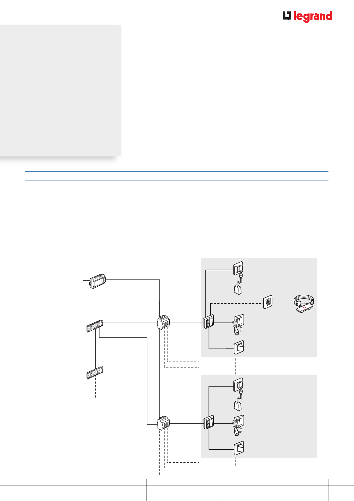
Wiring principle
4 control
units max.
{
230 V±
6-direction display unit
Cat. No. 0 766 60
(main control unit)
6-direction display unit
Cat. No. 0 766 60
(secondary control unit)
2
2 x 1.5 mm
Power supply
Cat. No. 0 782 89
6 x 0.6 mm2 pairs for 3 directions
6 x 0.6 mm2 pairs for 3 directions
2 x 6 x 0.6 mm
pairs for
3 directions
2
2 pairs* per direction
Management
module
Cat. No. 0 782 12
2
2 x 1.5 mm
Room 1
Room 2
Room 3
Room 4
2 pairs
2 pairs
1 pair
Door unit
Cat. No.
0 782 04
2 pairs
2 pairs
Bathroom call unit Cat. No. 0 766 64
Hand-held remote
Socket
Cat Nos. 0 782 41/46
or 0 782 45/47
Socket Cat No. 0 766 63
and corded push-button Cat No. 0 783 62
Corridor overdoor light unit
Cat. No. 0 766 72
Bathroom call unit
Cat. No. 0 766 64
control unit
Cat Nos. 0 782 01
or 0 782 02/03
* 2 x 0.6 mm2 pairs: 50 m max
2 x 0.9 mm2 pairs: 100 m max
Between the management module and the door unit
2 pairs* per direction
Management
module
Cat. No. 0 782 12
Room 5
Separate WC
MOSAIC NURSE CALL UNIT
1 pair
Door unit
Cat. No.
0 782 04
2 pairs
Socket Cat No. 0 766 63
and corded push-button Cat No. 0 783 62
Corridor overdoor light unit
Cat. No. 0 766 72
Room 7
INSTALLATION AND USER GUIDE
3
Page 4
DESCRIPTION OF THE SYSTEM ARCHITECTURE
Door unit
Cat. No. 0 782 04
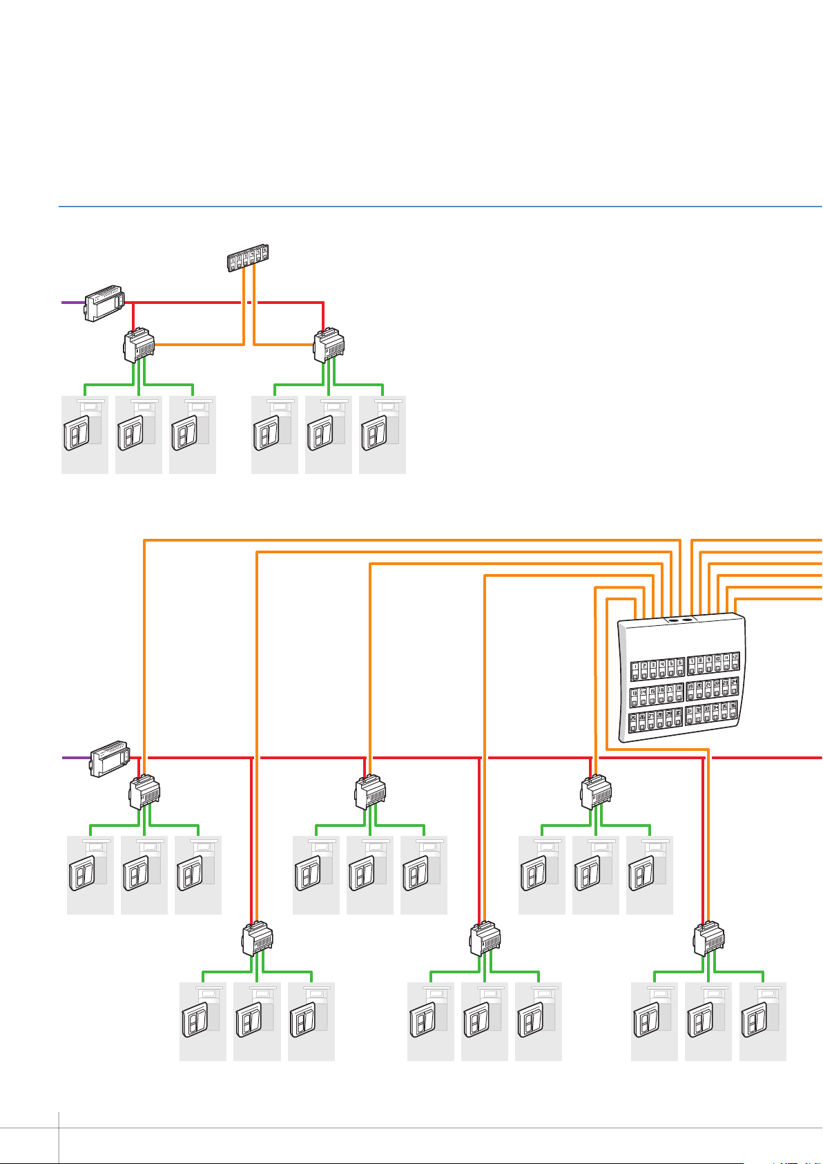
INSTALLATION PRINCIPLE FOR A WARD
6-room ward
Power supply
Cat. No. 0 782 89
230 V
Door unit
Cat. No. 0 782 04
Room
01
Door unit
Cat. No. 0 782 04
36-room ward
Management module
Cat. No. 0 782 12
Room
02
Door unit
Cat. No. 0 782 04
Room
03
6-direction display unit
Cat. No. 0 766 60
(main control unit)
Door unit
Cat. No. 0 782 04
Room
04
Door unit
Cat. No. 0 782 04
Management module
Cat. No. 0 782 12
Room
05
Door unit
Cat. No. 0 782 04
Room
06
Power supply
Cat. No. 0 782 89
230 V
Door unit
Cat. No. 0 782 04
Room
01
Management module
Cat. No. 0 782 12
Door unit
Cat. No. 0 782 04
Room
02
Door unit
Cat. No. 0 782 04
Room
03
Door unit
Cat. No. 0 782 04
Room
04
Management module
Cat. No. 0 782 12
Door unit
Cat. No. 0 782 04
Room
05
Door unit
Cat. No. 0 782 04
Room
07
Door unit
Cat. No. 0 782 04
Room
06
Management module
Cat. No. 0 782 12
Door unit
Cat. No. 0 782 04
Room
08
Door unit
Cat. No. 0 782 04
Room
09
Door unit
Cat. No. 0 782 04
Room
10
Management module
Cat. No. 0 782 12
Door unit
Cat. No. 0 782 04
Room
11
Door unit
Cat. No. 0 782 04
Room
13
Door unit
Cat. No. 0 782 04
Room
12
Management module
Cat. No. 0 782 12
Door unit
Cat. No. 0 782 04
Room
14
Door unit
Cat. No. 0 782 04
Room
15
Door unit
Cat. No. 0 782 04
Room
16
Management module
Cat. No. 0 782 12
Door unit
Cat. No. 0 782 04
Room
17
6-direction display units
Cat. No. 0 766 60 x 6 in
table control unit
Cat. No. 0 782 14 x 1
Door unit
Cat. No. 0 782 04
Room
18
4
Page 5
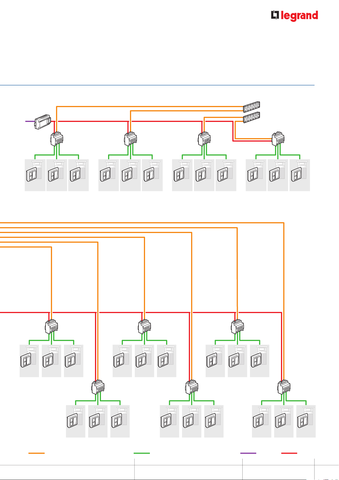
12-room ward
Power supply
Cat. No. 0 782 89
230 V
Door unit
Cat. No. 0 782 04
Room
01
Management module
Cat. No. 0 782 12
Door unit
Cat. No. 0 782 04
Room
02
Door unit
Cat. No. 0 782 04
Room
03
Door unit
Cat. No. 0 782 04
Room
04
Management module
Cat. No. 0 782 12
Door unit
Cat. No. 0 782 04
Room
05
Door unit
Cat. No. 0 782 04
Room
06
Door unit
Cat. No. 0 782 04
Room
07
Management module
Cat. No. 0 782 12
Door unit
Cat. No. 0 782 04
Room
08
Door unit
Cat. No. 0 782 04
Room
09
6-direction display units
Cat. No. 0 766 60 x 2
Door unit
Cat. No. 0 782 04
Room
10
Management module
Cat. No. 0 782 12
Door unit
Cat. No. 0 782 04
Room
11
Door unit
Cat. No. 0 782 04
Room
12
Door unit
Cat. No. 0 782 04
Room
19
Management module
Cat. No. 0 782 12
Door unit
Cat. No. 0 782 04
Door unit
Cat. No. 0 782 04
Room
20
6 x 0.6 mm2 pairs (50 m max) or 6 x 0.9 mm2 pairs (100 m max) 2 x 0.6 mm2 pairs (50 m max) or 2 x 0.9 mm2 pairs (100 m max)
Room
21
Door unit
Cat. No. 0 782 04
Room
22
Door unit
Cat. No. 0 782 04
Room
Door unit
Cat. No. 0 782 04
Management module
Cat. No. 0 782 12
Door unit
Cat. No. 0 782 04
23
Room
Room
24
25
Management module
Cat. No. 0 782 12
Door unit
Cat. No. 0 782 04
Room
26
Door unit
Cat. No. 0 782 04
Room
27
Door unit
Cat. No. 0 782 04
Room
28
Management module
Cat. No. 0 782 12
Door unit
Cat. No. 0 782 04
Room
29
Door unit
Cat. No. 0 782 04
Room
31
Door unit
Cat. No. 0 782 04
Room
30
DESCRIPTION OF THE SYSTEM ARCHITECTURE
Management module
Cat. No. 0 782 12
Door unit
Cat. No. 0 782 04
Room
32
Door unit
Cat. No. 0 782 04
Room
33
Management module
Cat. No. 0 782 12
Door unit
Cat. No. 0 782 04
Door unit
Cat. No. 0 782 04
Room
34
2G 1.5 mm² 2G 1.5 mm²
Room
35
Door unit
Cat. No. 0 782 04
Room
MOSAIC NURSE CALL UNIT
36
5
Page 6
DESCRIPTION OF THE SYSTEM ARCHITECTURE
Nurse call package
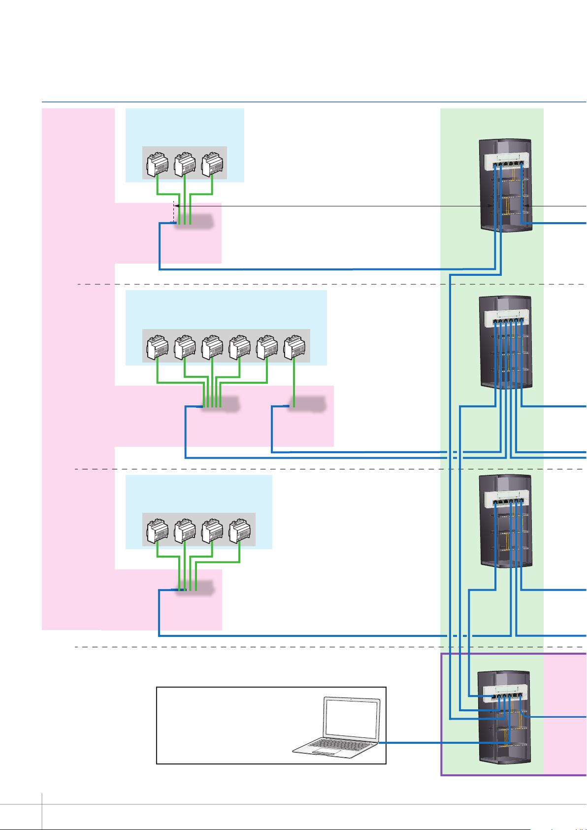
INSTALLATION PRINCIPLE WITH CALLFORWARDING OVER DECT AND TRACEABILITY ON TELEPHONE COUPLING PRODUCT TELEPHONY PACKAGE NOT SUPPLIED BY LEGRAND
3rd oor
9-room Neurology ward
Management module Cat. No. 0 782 12
Volt-free contact
interface unit
16 I/O to IP
Nurse call package
18-room Dermatology ward
Management module Cat. No. 0 782 12
Riser
VDI package
90 m max.
2nd oor
st
oor
1
Volt-free contact
interface unit
16 I/O to IP
Nurse call package
12-room Cardiology ward
Management module Cat. No. 0 782 12
Volt-free contact
interface unit
16 I/O to IP
Traceability on standard computer with icon
congured as a xed IP address.
For use by:
- Nurses
- Maintenance
- Management
Congured by the network integrator.
Volt-free contact
interface unit
16 I/O to IP
Main cross-connect
cabinet
ELV equipment room
6
Page 7
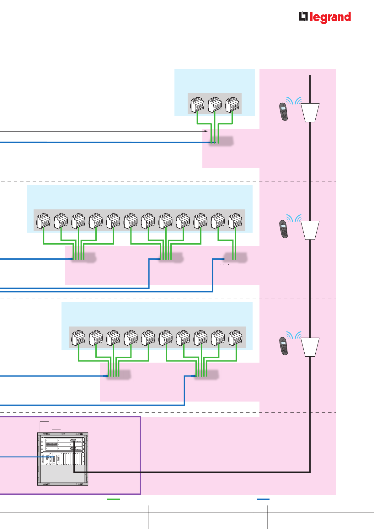
9-room Ophthalmology ward
Nurse call package
Telephony packageTelephony package
Management module Cat. No. 0 782 12
90 m max.
Volt-free contact
interface unit
16 I/O to IP
Nurse call package
36-room Urology ward
Management module Cat. No. 0 782 12
Volt-free contact
interface unit
16 I/O to IP
Volt-free contact
interface unit
16 I/O to IP
Volt-free contact
interface unit
16 I/O to IP
DECT
TERMINAL
DECT
TERMINAL
Autocom cabinet
PABX/IPBX
RS232
Nurse call package
30-room General surgery department
Management module Cat. No. 0 782 12
Volt-free contact
interface unit
16 I/O to IP
Telephone
coupler with
xed IP address
Volt-free contact
interface unit
16 I/O to IP
DECT
TERMINAL
Cables with 2 x 0.6 mm2 pairs (50 m max) or 0.9 mm2 pairs (100 m max)
DESCRIPTION OF THE SYSTEM ARCHITECTURE
UTP/FTP cable Cat. 5e minimum
MOSAIC NURSE CALL UNIT
7
Page 8
DESCRIPTION OF THE SYSTEM ARCHITECTURE
Telephony package
Nurse call package
23
r
2or
2
r
V
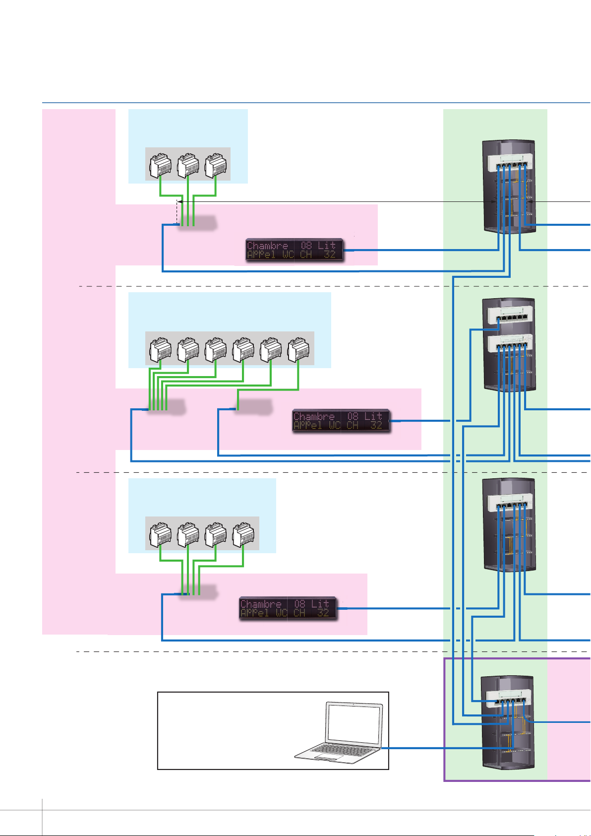
INSTALLATION PRINCIPLE WITH CALLFORWARDING OVER DECT AND TRACEABILITY ON TELEPHONE COUPLING PRODUCT AND CORRIDOR DISPLAY UNITS TELEPHONY PACKAGE NOT SUPPLIED BY LEGRAND
rd
3
oor
9-room Neurology ward
Management module Cat. No. 0 782 12
Volt-free contact
interface unit
16 I/O to IP
Nurse call package
18-room Dermatology ward
Management module Cat. No. 0 782 12
Volt-free contact
interface unit
16 I/O to IP
Volt-free contact
interface unit
16 I/O to IP
230 V
o
or PoE
Riser
VDI package
90 m max.
230 V
or PoE
2nd oor
st
oor
1
Nurse call package
12-room Cardiology ward
Management module Cat. No. 0 782 12
Volt-free contact
interface unit
16 I/O to IP
Traceability on standard computer with icon
congured as a xed IP address.
For use by:
- Nurses
- Maintenance
- Management
Congured by the network integrator.
230 V
or PoE
o
Main cross-connect
cabinet
ELV equipment room
8
Page 9
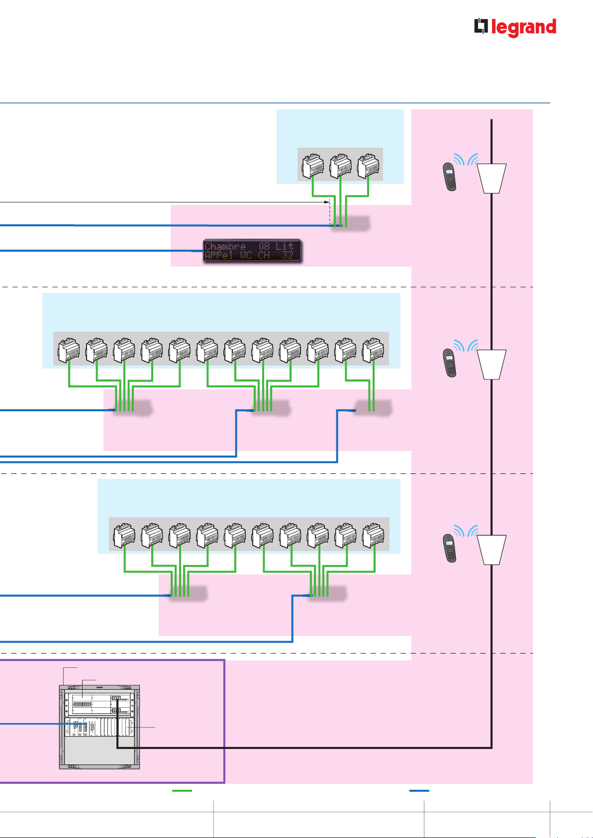
9-room Ophthalmology ward
Nurse call package
Telephony package
V
Management module Cat. No. 0 782 12
90 m max.
Volt-free contact
interface unit
16 I/O to IP
230 V
E
or PoE
Nurse call package
36-room Urology ward
Management module Cat. No. 0 782 12
Volt-free contact
interface unit
16 I/O to IP
Volt-free contact
interface unit
16 I/O to IP
Volt-free contact
interface unit
16 I/O to IP
DECT
TERMINAL
DECT
TERMINAL
Autocom cabinet
PABX/IPBX
RS232
Nurse call package
30-room General surgery department
Management module Cat. No. 0 782 12
Volt-free contact
interface unit
16 I/O to IP
Telephone
coupler with
xed IP address
Volt-free contact
interface unit
16 I/O to IP
DECT
TERMINAL
Cables with 2 x 0.6 mm2 pairs (50 m max) or 0.9 mm2 pairs (100 m max)
PRESENTATION AND INSTALLATION OF DEVICES
UTP/FTP cable Cat. 5e minimum
MOSAIC NURSE CALL UNIT
9
Page 10
DESCRIPTION OF THE SYSTEM ARCHITECTURE
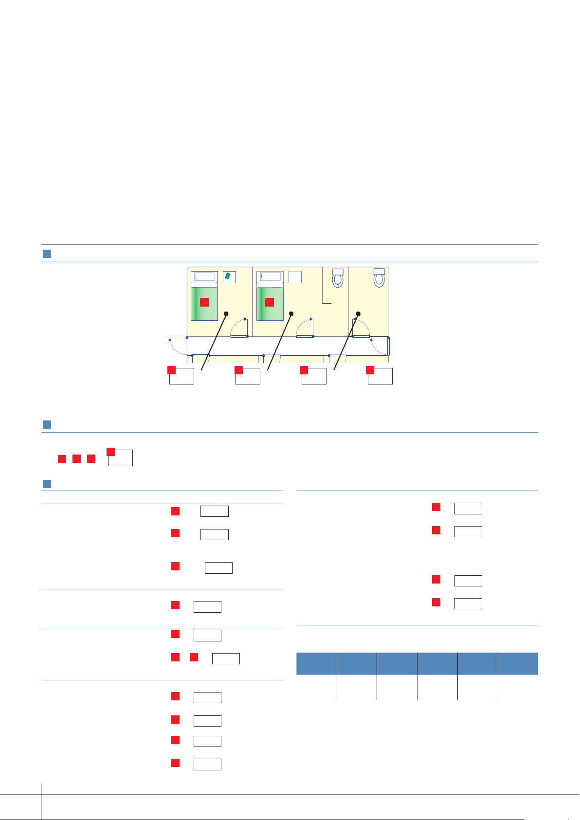
SELECTION GUIDE: HOW TO DRAW UP YOUR LIST OF EQUIPMENT
1
Gather the following information
D
D
D
D
A B C D
Number of
separate
rooms
2
Calculate the number of directions
Number
of rooms
with WC
To determine the number of directions, simply add:
B C
A
+ + =
3
Draw up your list of equipment
E
Nurses' station and management equipment
Display unit Cat. No. 0 766 60 = E/6 or
display units
Management module
Cat. No. 0 782 12 = E/3 or modules
Option:
Table control unit
Cat. No. 0 782 14 = E/36 or control units
Corridor equipment
Corridor overdoor light units
Cat. No. 0 766 72 =E or overdoor lights
Room/bathroom equipment
Door unit Cat. No. 0 782 04 = E or door units
Bathroom call unit
Cat. No. 0 766 64 = B + C or call units
Bed equipment
Socket for corded push-button
Cat. No. 0 766 63 =D or sockets
Corded push-button
Cat. No. 0 783 62 =D or corded buttons
OR
Magnetic socket Cat. No. 0 782 46 =D or sockets
Hand-held remote control unit
for call only Cat. No. 0 782 01 =D or hand-held
remote
control units
10
Number of
separate WCs
Number
of beds
Bed equipment (continued)
OR
Magnetic socket Cat. No. 0 782 47 =D or sockets
Hand-held remote control unit for
call only Cat. Nos. 0 782 02/03 =D or hand-held
remote
control units
Option:
Shunt plug for biomedical
alarm Cat. No. 0 782 07 =D or plugs
Socket for biomedical alarm
Cat. No. 0 771 50 =D or sockets
Power supply:
Power supply Cat. No. 0 782 89
Number of power supplies to be calculated using the table below
0 782 04 0 766 72 0 766 64 0 782 01/
02/03
0.7 W 0.9 W 0.7 W 0.8 W 1 W 0.4 W per
Recommendation: 1 power supply for 36 directions (corresponds to 30% of
simultaneous calls max.)
0 782 12 0 766 60
direction
Page 11

PRESENTATION AND
1 2
3
4 5 6 7
INSTALLATION
OF DEVICES
0 766 60: 6DIRECTION* CALL DISPLAY UNIT
Direction
identification*
Mute button
Identification
labelssupplied
Main display unit: used to monitor rooms in the ward from the
nurses' station.
Secondary display unit: used to transfer information from the
main display unit. 4 secondary display units max.
Indicates calls by lighting up numbered indicator lights and
generating an audible signal.
Can indicate several calls simultaneously.
Displays the call and nurse presence
and mute setting.
Calls can be transferred to 4 other display units (treatment room,
rest area, etc).
Supplied without plate.
Supplied with sheets of numbered stickers from 1 to 99.
Technical characteristics
n Power supply: 24 V=
n Consumption: min. 0.4 W - max. 2.8 W
n Operating temperature: 5 to 40°C
n Storage temperature: -20 to 70°C
n Protection index: IP40
n Dimensions: 135 x 22.5 mm
n Installation:
- On table control unit Cat. No. 0 782 14
- Flush-mounted in box depth 50 mm Cat. No. 0 800 53
- Surface-mounted in box depth 40 mm Cat. No. 0 802 86
n Sound level:
- 65 dB (A) at 1 m placed on table
- 75 dB (A) fixed to wall 1.60 m off the floor
- 62 dB (A) at 1 m placed on table
- 72 dB (A) fixed to wall 1.60 m off the floor
ConnectionPerforms the main and secondary display functions.
0 766 60
1- Management module terminals
2- Room 6 terminals
3- Room 1 terminals
4- Room 2 terminals
5- Room 3 terminals
6- Room 4 terminals
7- Room 5 terminals
* Direction: room from which the calls originate
PRESENTATION AND INSTALLATION OF DEVICES
MOSAIC NURSE CALL UNIT
11
Page 12
PRESENTATION AND INSTALLATION OF DEVICES
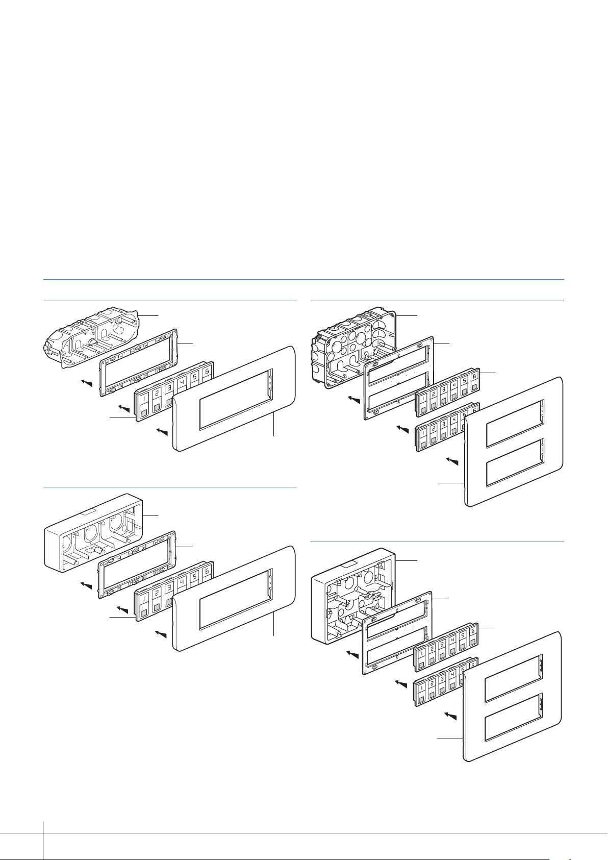
0 766 60: 6DIRECTION* CALL DISPLAY UNIT CONTINUED
Flush-mounted wall installation Flush-mounted 2-gang wall installation
Cat. No. 0 800 53
Cat. No. 0 766 60
Surface-mounted wall installation
Cat. No. 0 802 86
Cat. No. 0 766 60
Cat. No. 0 802 53
Cat. No. 0 802 53
Cat. No. 0 788 16
Cat. No. 0 801 26
Cat. No. 0 802 66
Cat. No. 0 766 60
Cat. No. 0 788 16
Cat. No. 0 788 36
Surface-mounted 2-gang wall installation
Cat. No. 0 802 76
Cat. No. 0 802 66
Cat. No. 0 766 60
* Direction: room from which the calls originate
12
Cat. No. 0 788 36
Page 13

0 782 12: 3DIRECTION MANAGEMENT MODULE*
3
4567
2
Option of forwarding:
- for indicator
- for buzzer via a solid state relay
- to DECT, via a telephone coupling product
- to master indicator (lights up if the indicator on at least one of
the 3 directions is lit up).
Technical characteristics
n Power supply: 24 V=
n Consumption (min): 39 mA
(max): 300 mA
n Operating temperature: 5 to 40°C
n Storage temperature: -20 to 70°C
n Size: 4 DIN modules
ConnectionManages 3 directions.
1
1- 24 V= power supply terminals
2- Master indicator or solid state relay
terminals
3- Call display unit terminals
4- Door unit direction 1
5- Door unit direction 2
6- Door unit direction 3
7- Volt-free contact for DECT call
forwarding or indicator or buzzer
Max : 24 V 0,5 A
* Direction: room from which the calls originate
PRESENTATION AND INSTALLATION OF DEVICES
n Contact beat frequency
Normal call (0.5 Hz)
Emergency call (1 Hz)
MOSAIC NURSE CALL UNIT
13
Page 14
PRESENTATION AND INSTALLATION OF DEVICES
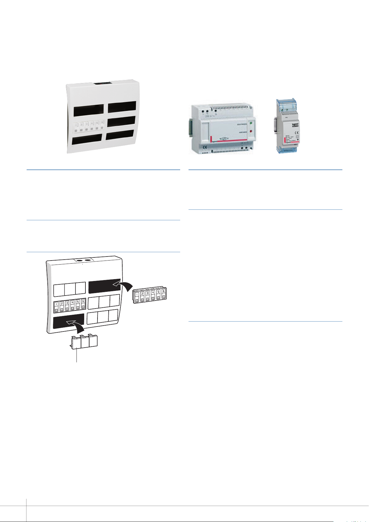
0 782 14: TABLE CONTROL UNIT
Support frame which can take up to 6 display units
Cat.No.076660.
Makes it easier to run cables when installing several display units.
Fit blanking plates over unused positions.
Technical characteristics
n Protection index: IP 40 with blanking plates
n Dimensions: 310 x 295 x 75 mm (36 modules)
Installation
Cat. No. 0 770 71
0 782 89/0 035 67 OR E49: POWER SUPPLIES
Cat. No. 0 782 09: Powers the system with SELV.
Recommendation: 1 power supply for 36 directions (corresponds
to 30% of simultaneous calls max.).
Technical characteristics
n Supply voltage: 230 VA + 10% - 50/60 Hz
n Output voltage: 24 V=
n Max. current: 2 A
n Max. power: 48 W
n Operating temperature: 5 to 40°C
n Storage temperature: -20 to 70°C
n Protection index: IP30
n Size: 6 DIN modules
Cat. No. 0 035 67 or E49: Powers the solid state relay for
information transfer (indicator or buzzer).
Technical characteristics
n Supply voltage: 230 VA
n BUS output voltage: 27 V=
n Max. BUS current: 600 mA
n Max. power: 21.5 W
n Max. consumption: 26.8 W
n Operating temperature: 5 to 40°C
n Storage temperature: -20 to 70°C
n Protection index: IP20
n Size: 2 DIN modules
14
Page 15
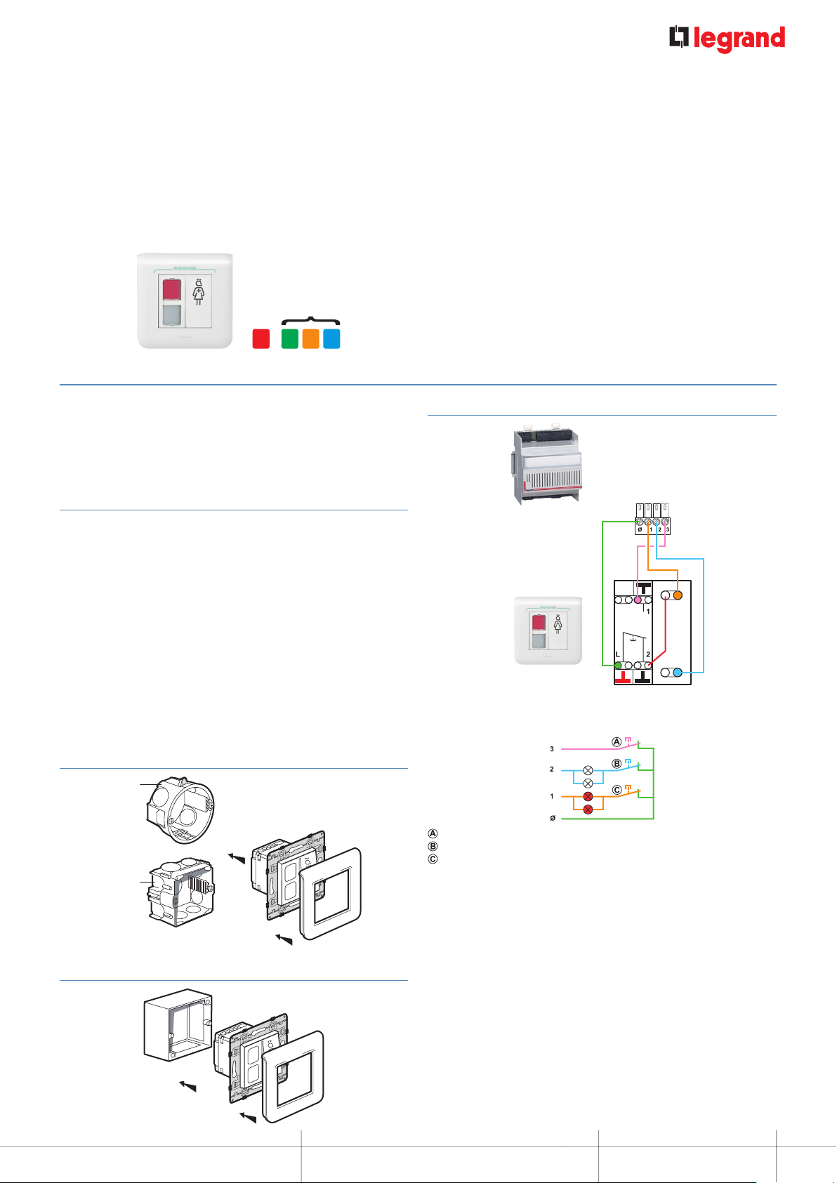
0 782 04: DOOR UNIT
Not used
Consisting of 2 white indicators to be covered with stickers (red,
green, orange or blue) and a push-button for acknowledging the
call and nurse presence.
Recommendation: Place the red sticker over the call indicator
(top indicator).
Technical characteristics
n Power supply: via management module Cat. No. 0 782 12
n Operating temperature: 5 to 40°C
n Storage temperature: -20 to 70°C
n Antimicrobial
n Protection index: IP20
n Dimensions (H x W x D): 82 x 82 x 43 mm
n Installation:
- in 1-gang (2 modules) flush-mounting box Cat. No. 0 800 41
or Cat. No. 0 801 41 (concrete)
- in surface-mounting box Cat. No. 0 802 81 (IP 20)
n LED indicators with resistor in parallel:
- Impedance: 1 kΩ
- DC voltage: 9 to 31 V
Flush-mounted wall installation
Cat. No. 0 800 41
Connection (from 15W22)
Management
module
Cat. No. 0 782 12
R
Door unit
Cat. No. 0 782 04
W
R - Red LED indicator
W - White LED indicator
Cat. No. 0 801 41
Surface-mounted wall installation
- Bathroom or biomedical pull cord
- Corded push-button or hand-held remote control
- Door unit
Antimicrobial
Antimicrobial
PRESENTATION AND INSTALLATION OF DEVICES
MOSAIC NURSE CALL UNIT
15
Page 16

PRESENTATION AND INSTALLATION OF DEVICES
Not used
0 766 85: BATHROOM CALL UNITS OR CALL BUTTON
Technical characteristics
n Power supply: via management module Cat. No. 0 782 12
n Operating temperature: 5 to 40°C
n Storage temperature: -20 to 70°C
n Antimicrobial
n Protection index: IP20
n Dimensions (H x W x D): 82 x 82 x 43 mm
n Installation:
- in 1-gang (2 modules) flush-mounting box Cat. No. 0 800 41 or
Cat. No. 0 801 41 (concrete)
- in surface-mounting box Cat. No. 0 802 81 (IP 20)
Recommendation: Place the red sticker over the call indicator (top
indicator).
Flush-mounted wall installation
Cat. No. 0 800 41
Cat. No. 0 801 41
Antimicrobial
Bathroom call button connection (from 15W22)
R
Door unit
Cat. No. 0 782 04
W
Bathroom call
button
Cat. No. 0 766 85
R
R - Red LED indicator
W - White LED indicator
Bedroom call button connection (from 15W22)
Surface-mounted wall installation
16
R
Door unit
Cat. No. 0 782 04
W
Antimicrobial
Bedroom call
button
Cat. No. 0 766 85
R
R - Red LED indicator
W - White LED indicator
Page 17

0 766 63: SOCKET FOR CORDED PUSHBUTTON
0 783 62: CORDED PUSHBUTTON
Socket for corded push-button or biomedical alarm.
Supplied on 2-module plate with blanking plate.
Technical characteristics
n Power supply: via management module Cat. No. 0 782 12
n Operating temperature: 5 to 40°C
n Storage temperature: -20 to 70°C
n Protection index: IP20
n Dimensions: 82 x 82 x 36 mm
n Installation:
- in 1-gang (2 modules) flush-mounting box Cat. No. 0 800 41 or
Cat. No. 0 801 41 (concrete)
- on the wall with surface-mounting box Cat. No. 0 802 81
n 12 mm fixing centres
Connection
Socket for
corded pushbutton
Cat. No. 0 766 63
Allows patients to call a nurse via the door unit.
For use in conjunction with socket Cat. No. 0 766 63.
With 12 mm fixing centre plug for 2P socket Cat. No. 0 771 50.
Technical characteristics
n Power supply: via socket for corded push-button
n Operating temperature: 5 to 40°C
n Storage temperature: -20 to 70°C
n Protection index: IP20
n Cord length: 2 m
n Ejectable from 45° angle
n Factory-fitted NC contact.
NO contact possible by replacing the brown wire in the plug with
the black wire.
Conductor marking
Factory wiring
Connect
blue and
brown
Door unit
Cat. No. 0 782 04
R - Red LED indicator
W - White LED indicator
R
W
Closed in rest mode
PRESENTATION AND INSTALLATION OF DEVICES
MOSAIC NURSE CALL UNIT
17
Page 18

PRESENTATION AND INSTALLATION OF DEVICES
0 782 41
0 782 01
0 782 41/46: SOCKETS FOR HANDHELD REMOTE CONTROL UNITS
Sockets Cat. No. 0 782 41 for mounting in a strip and 0 782 46 for
call-only hand-held remote control unit.
Magnetic connection between hand-held unit and socket: can be
ejected in any direction with pull-out force designed to avoid any
damage to the equipment.
Antimicrobial.
Non-indexed magnetic connection socket for hand-held remote
control unit Cat. No. 0 782 01.
0 782 46
Technical characteristics
n Power supply: via the door unit
n Operating temperature: 5 to 40°C
n Storage temperature: -20 to 70°C
n Antimicrobial
n Protection index: IP40
n Dimensions:
- Cat. No. 0 782 41: 45 x 45 x 36 mm
- Cat. No. 0 782 46: 82 x 82 x 36 mm
n Installation:
- in 1-gang flush-mounting box (2 modules)
- on wall with surface-mounting box Cat. No. 0 802 81
- in a strip using special holder supplied
• Flush-mounted wall installation with 1-gang
flush-mounting box
• Surface-mounted wall installation with box Cat. No. 0 802 81
• Connection
Example: 1 bed in a room.
Hand-held unit
socket
Cat. No. 0 782 46
Door unit
Cat. No. 0 782 04
1234
+-
R
W
18
R - Red LED indicator
W - White LED indicator
Page 19

0 782 45/47: SOCKETS FOR HANDHELD REMOTE CONTROL UNITS
0 782 45
0 782 03
Sockets Cat. Nos. 0 782 45 and 0 782 47 for hand-held remote
control units for calls and controls.
Magnetic connection between hand-held unit and socket: can be
ejected in any direction with pull-out force designed to avoid any
damage to the equipment.
Antimicrobial.
Indexed magnetic connection socket for hand-held remote control
unit Cat. Nos. 0 782 02 and 782 03.
0 782 47
0 782 02
Technical characteristics
n Power supply:
- via the door unit for nurse calls
- via remote control module Cat. No. 0 783 77 or 0 783 78 or 0
783 79 for lighting and roller blinds
n Operating temperature: 5 to 40°C
n Storage temperature: -20 to 70°C
n Antimicrobial
n Protection index: IP40
n Dimensions:
- Cat. No. 0 782 45: 45 x 45 x 36 mm
- Cat. No. 0 782 47: 82 x 82 x 36 mm
n Installation:
- in 1-gang flush-mounting box (2 modules)
- on wall with surface-mounting box Cat. No. 0 802 81
Flush-mounted wall installation with 1-gang flushmountingbox
Surface-mounted wall installation with box Cat. No. 0 802 81
Connection
Example: 1 bed in a room.
Door unit
Cat. No. 0 782 04
R - Red LED indicator
W - White LED indicator
+-
R
W
Hand-held unit
socket
Cat. No. 0 782 47
PRESENTATION AND INSTALLATION OF DEVICES
12 11 10 987
123456
MOSAIC NURSE CALL UNIT
19
Page 20

PRESENTATION AND INSTALLATION OF DEVICES
0 782 01/02/03: HANDHELD REMOTE CONTROL UNITS
Allow patients to call a nurse (using an NC push-button with call
confirmation indicator) via the door unit.
Magnetic connection between hand-held units and sockets: can
be ejected in any direction with pull-out force designed to avoid
any damage to the equipment.
These products are compatible with other nurse call systems with
an NC (Normally Closed) contact on 2 terminals and LED call
confirmation indicator on 2 terminals.
Recommended cleaning: use wipes impregnated with detergent
for food contact surfaces (Dettol, etc).
Hand-held remote control unit for call only (corded push-button)
Cat. No. 0 782 01
For use with socket Cat. No. 0 782 41 or 0 782 46.
2.50 m cord
Nurse call
button
Red call confirmation
indicator
Connection
Hand-held remote control unit for calls and controls
Cat. No. 0 782 02
For use with socket Cat. No. 0 782 45 or 0 782 47.
1
3
2
Red call confirmation
indicator
1- Nurse call button
2- Reading light control (NO push-button)
3- Room lighting control (NO push-button)
Hand-held remote control unit for calls and controls
Cat. No. 0 782 03
For use with socket Cat. No. 0 782 45 or 0 782 47.
1
6
5
7
4
2
3
20
1
0 782 01
+ –
23
24 V
0 782 01
1- Nurse call button
2- Reading light control (NO push-button)
3- Room lighting control (NO push-button)
4- Red call confirmation indicator
5 and 6- Roller blind control (NO push-button)
7- Free function button (NO push-button)
4
0 782 41/46
Page 21

0 782 43: CLAMP FOR CORDED PUSHBUTTON
79,7
17,936
123456
Connection
0 782 03 0 782 03
O
I
12 11 10 987
+ –
24 V
Technical characteristics
n Power supply: via sockets for hand-held remote control units
n Operating temperature: 5 to 40°C
n Storage temperature: -20 to 70°C
n Antimicrobial
n Protection index: IP 67 (without plug)
n Cord length: 2.5 m
n Can be fixed or held in place with clamp Cat. No. 0 782 43
n LED indicators with resistor in parallel:
- Impedance: 12.45 kΩ
- DC voltage: 9 to 31 V
For holding the corded push-button within reach: on bedding,
clothes or the arm of a chair.
Overall dimensions
0 782 45/47
PRESENTATION AND INSTALLATION OF DEVICES
MOSAIC NURSE CALL UNIT
21
Page 22

PRESENTATION AND INSTALLATION OF DEVICES
35°C
+
+
+
+
+
+
+
+
+
+
+
0 783 77/78/79: REMOTE CONTROL MODULES
These units are used to control SELV functions (lighting, roller
blinds, and one additional function) via hand-held remote control
units.
For mounting in suspended ceilings or in technical cabinets
between the rooms.
This product must be used on a single phase.
+
0°C
230 VA
110 VA
500 W
250 W 500 W 250 VA 250 VA 250 VA 250 VA 1 x 250 VA
2 A
1000 W
4.3 A
500 VA
2 A
Technical characteristics
n Power supply: 100 - 240 V
n Operating temperature: 0 to 35°C
n Storage temperature: -20 to 70°C
n Dimensions: 230 x 71 x 44 mm
n Installation: in suspended ceiling or technical cabinet
+
500 VA
2 A
500 VA
2 A
500 VA
Remote control module for luminaires or bedhead strips for controlling 4 lighting outputs Cat. No. 0 783 77
Compatible with hand-held remote control unit Cat. No. 0 782 02.
OFF
C10
0 782 45/47
+
1 x 500 VA
2 A
2 A
22
0 782 02
0 782 02
Page 23

Remote control module for luminaires or bedhead strips for controlling 2 lighting outputs and roller blinds with mechanical stop
L1
input
or
DA-DA
(DALI)
L
Cat. No. 0 783 78
Compatible with hand-held remote control unit Cat. No. 0 782 03.
10 A max
CH.1
L1
L2
L3
N
C10
C10
0 782 45/47
10 A max
1
1
1
O
I
1
2
3
6
0 782 03
5
4
8
7
1
OFF
Remote control module for roller blinds and for luminaires or bedhead strips for controlling 2 lighting outputs: room lighting
dimmer, reading light ON/OFF and roller blinds Cat. No. 0 783 79
Compatible with hand-held remote control unit Cat. No. 0 782 03.
L2
L3
OFF
N
C10 C10
10 A max
L
1
CH.1
1
10 A max
1
O
I
1
0 782 45/47
1
2
3
6
5
4
8
7
> 1.5 s > 1.5 s
0 782 03
1
PRESENTATION AND INSTALLATION OF DEVICES
< 1.5 s
< 1.5 s
MOSAIC NURSE CALL UNIT
23
Page 24

PRESENTATION AND INSTALLATION OF DEVICES
9 804 12: SPARE PART FOR BATHROOM CALL
0 766 64: BATHROOM CALL PULLCORD 18W10
PULLCORD
Bathroom call unit with vertical pull-cord button and integrated
LED indicator.
Technical characteristics
n Power supply: via door unit Cat. No. 0 782 04
n Consumption: 0.8 W
n Operating temperature: 5 to 40°C
n Storage temperature: -20 to 70°C
n Protection index: IP20
n Dimensions: 82 x 82 x 43 mm
n Installation:
- surface-mounted with box Cat. No. 0 802 81
- flush-mounted in 1-gang (2 modules) flush-mounting box
depth 40 mm Cat No. 0 819 41 or 0 801 41
n Antibacterial
Connection
R
Door unit
Cat. No. 0 782 04
B
Spare cord in case one breaks or is lost.
Technical characteristics
n Antibacterial
n Length 1.5 m
Bathroom call unit
Cat. No. 0 766 64
R - Red LED indicator
W - White LED indicator
24
R
Page 25

0 766 72: DOUBLE DISPLAY CORRIDOR OVERDOOR LIGHT UNIT
Double indicator (red/white).
Displays calls and nurse presence in the corridor.
With long-life LEDs.
Caution: only this catalogue number is compatible with the
Mosaic system.
Technical characteristics
n Power supply: via door unit Cat. No. 0 782 04
n Consumption: 1.2 W
n Operating temperature: 5 to 40°C
n Storage temperature: -20 to 70°C
n Protection index: IP20
n Dimensions: 82 x 82 x 43 mm
n Installation:
- surface-mounted with box Cat. No. 0 802 81
- flush-mounted in 1-gang (2 modules) flush-mounting box
depth 40 mm Cat No. 0 819 41 or 0 801 41
Connection
Corridor overdoor
light unit
Cat. No. 0 766 72
RB
R
Door unit
Cat. No. 0 782 04
B
R - Red LED indicator
W - White LED indicator
PRESENTATION AND INSTALLATION OF DEVICES
MOSAIC NURSE CALL UNIT
25
Page 26

PRESENTATION AND INSTALLATION OF DEVICES
0 766 71: CALL TRANSFER UNIT FOR CORRIDORS
Transfers calls from a ward into the corridor.
Technical characteristics
n Power supply: 27 V= (via indicator power supply)
n Operating temperature: 5 to 40°C
n Storage temperature: -20 to 70°C
n Protection index: IP20
n Dimensions (H x W): 82 x 82 mm
n Installation:
- in 1-gang flush-mounting box
- surface-mounted with box Cat. No. 0 802 81
0 766 42: ELECTRONIC BUZZER
Audible call transfer from a ward.
Technical characteristics
n Power supply: 27 V= (via power supply Cat. No. 0 035 67)
n Consumption: 9 mA
n Operating temperature: -10°C to +55°C
n Storage temperature: -20 to 70°C
n Protection index: IP 41-IK 05
n Sound level: 80 dB(A) at 1 m
n Overall dimensions (H x W): 45 x 45 mm
Flush-mounted wall installation in 1-gang screw flushmounting box
Cat. No. 0 802 51
Cat. No. 0 787 22
26
Surface-mounted wall installation with box Cat. No. 0 802 81
Cat. No. 0 802 51
Cat. No. 0 787 22
Page 27

+
0 771 50 + 0 782 07: BIOMEDICAL CALL PLUG AND SOCKET
Signals the end of a cycle via an alarm on the nurse call system.
For connection to portable electrical medical devices such as
syringe pumps, respirators, etc.
Comprises:
- Socket Cat. No. 0 771 50
- Shunt plug Cat. No. 0 782 07:
For biomedical alarm standby.
Used with socket Cat. No. 0 771 50.
Technical characteristics
n Power supply: via door unit Cat. No. 0 782 04
n Operating temperature: 5 to 40°C
n Storage temperature: -20 to 70°C
n Protection index: IP20
n Overall dimensions (H x W): 45 x 22.5 mm
n Installation:
- in 1-gang flush-mounting box with universal Batibox support
Cat. No. 0 802 51
- surface-mounted with box Cat. No. 0 802 81 and universal
Batibox support Cat. No. 0 802 51
- can be installed in trunking, or in bedhead strips or trunking
units
Flush-mounted wall installation in 1-gang
flush-mounting box with support Cat. No. 0 802 51
Biomedical socket connection (emergency call)
Biomedical socket
Cat. No. 0 771 50
R
Door unit
Cat. No. 0 782 04
B
R - Red LED indicator
W - White LED indicator
Armchair socket connection (normal call)
Armchair socket
Cat. No. 0 771 50
Flush-mounted wall installation in 1-gang
flush-mounting box with support Cat. No. 0 802 51
PRESENTATION AND INSTALLATION OF DEVICES
Door unit
Cat. No. 0 782 04
R - Red LED indicator
W - White LED indicator
R
W
MOSAIC NURSE CALL UNIT
27
Page 28

OPERATING MODE
CALL + NURSE PRESENT
1 - Patient calls from room
BEEEP
OR
The patient calls from their room by
pressing the corded push-button or
hand-held remote control unit.
From the nurses' station, the nurse
3
acknowledges the call by pressing
the mute button. The red indicator
changes from flashing to steady and
the buzzer stops.
2 - Nurse present in the room
1
On entering the room, the nurse
signals her presence by pressing the
door unit push-button.
21
The door unit indicator and the corridor
overdoor light flash red slowly.
The door unit indicator and the corridor
4
overdoor light change from flashing red
to steady red.
2
The red door unit indicator goes out
andthe white indicator lights up.
The corridor overdoor light changes
fromred to white.
In the nurses' station, the room number
lights up red and flashes slowly, and the
buzzer beeps slowly.
In the nurses' station, the red indicator
goes out and the yellow indicator returns
to steady state.
3 - Acknowledgement of the call
1
28
On leaving the room, the nurse presses
the door unit push-button and clears
the call.
All the indicators and the overdoor
light go out.
Page 29

BATHROOM CALL + NURSE PRESENT
1 - Patient calls from bathroom
BEEEP
BEEEP
1
The patient calls from the bathroom
bypulling the cord.
3
Muting is not possible from the nurses'
station. The nurse must go to the
patient's bathroom.
2 - Nurse present in the room
1
On entering the room, the nurse
signals her presence by pressing the
door unit push-button.
Since bathroom calls are priority calls, the nurse must go to the room. Muting is not possible.
2
The door unit indicator, the indicator in
the bathroom and the corridor overdoor
light flash red quickly.
2
The door unit red indicator and the
corridor overdoor light go out. The door
unit indicator and the corridor overdoor
light come on with a steady white light.
In the nurses' station, the room number
is displayed, the indicator flashes red
quickly and the buzzer beeps quickly.
In the nurses' station, the red indicator
goes out and the yellow indicator returns
to steady state.
3 - Acknowledgement of the call
1
On leaving the room, the nurse presses
the door unit push-button and clears
the call.
All the indicators and the overdoor
light go out.
MOSAIC NURSE CALL UNIT
MOSAIC NURSE CALL UNIT
29
Page 30

OPERATING MODE
CALL FOR NURSE ASSISTANCE EMERGENCY
1 - Patient calls from room
2 - Nurse present in the room
3 - Nurse assistance request
OR
The patient calls from their room by
1
pressing the corded push-button or
hand-held remote control unit.
4 5 6
Muting is not possible
from the nurses' station.
The nurse must go to the
patient's room.
On leaving the room, the
7
nurse presses the door unit
push-button and clears
thecall.
All the indicators and the
overdoor light go out.
On entering the room, the
2nd nurse presses the door
unit push-button.
The door unit indicators and the
2 3
corridoroverdoor light flash quickly,
alternating red and white.
BEEEP
In the nurses' station, the indicator
flashes quickly, alternating red and
yellow; the buzzer beeps quickly.
The door unit red indicator
andthe corridor overdoor
lightgo out. The door unit
indicator and the corridor
overdoor light come on with
asteady white light.
BEEEP
In the nurses' station, the red
indicator goes out and the
yellow indicator returns to
steady state.
30
Page 31

NURSE PRESENT + CALL FROM ANOTHER ROOM
1 - Patient calls from room 1
2 - Nurse present in room 1
3 - Another patient calls from room 2
BEEEP
BEEEP
OR
1 2
The patient calls from
room2 by pressing the
corded push-button or
The door unit indicator and
the corridor overdoor light for
room 2 flash red slowly.
hand-held remote control
unit.
On entering room 2, the
3 4
nurse presses the door
unitpush-button.
In room 1 (and in the other
rooms in the ward where a
nurse is present): the door
unit indicators and corridor
overdoor lights stop flashing.
On leaving room 1, nurse 1
5 6
presses the door unit pushbutton and clears the call.
All the indicators and the
In the nurses' station, room
number 1 stops flashing and
returns to a steady yellow
light.
overdoor light go out.
In the nurses' station, room
number 2 lights up red and
flashes slowly, and the buzzer
beeps slowly.
On leaving room 2, the
nurse presses the door unit
push-button and clears
thecall.
All the indicators and the
overdoor light go out.
In room 1 (and in the other
rooms in the ward where a
nurse is present): the door
unit indicators and corridor
overdoor lights flash white
slowly.
In the nurses' station, room
number 2 goes out.
MOSAIC NURSE CALL UNIT
MOSAIC NURSE CALL UNIT
31
Page 32

OPERATING MODE
NURSE PRESENT + CALL FROM ANOTHER BATHROOM
1 - Patient calls from room 1
2 - Nurse present in room 1
3 - Another patient calls from bathroom 2
1
The patient calls
from bathroom 2 by
pulling the cord.
On entering room 2,
3 4
the nurse presses
the door unit pushbutton.
On leaving room 1,
5 6
nurse 1 presses the
door unit pushbutton and clears
the call.
All the indicators
and the overdoor
light go out.
2
The door unit indicator, the indicator in
the bathroom and the corridor overdoor
light flash red quickly.
In room 1 (and in the other rooms in the
ward where a nurse is present): the door
unit indicators and corridor overdoor
lights stop flashing.
In the nurses' station, room number1
stops flashing and returns to a steady
yellow light.
BEEEP
BEEEP
In the nurses' station, the
room number is displayed,
the indicator flashes red
quickly and the buzzer beeps
quickly.
On leaving room 2,
nurse 2 presses the door
unit push-button and
clears the call.
All the indicators and the
overdoor light go out.
In room 1 (and in the other
rooms in the ward where a
nurse is present):
the door unit indicators and
corridor overdoor lights
flash white quickly.
In the nurses' station,
room number 2 goes out.
32
Page 33

CALL PRIORITIES
PRIORITY
+
CALL TYPE CONTROL DEVICE
Emergency
call (help)
from
bathroom
Emergency
call (help)
from
bedroom
OR
Biomedical
alarm
DISPLAY ON DOOR UNIT
AND CORRIDOR OVERDOOR
LIGHT
DISPLAY ON
CONTROL
UNIT
BEEEP
BEEEP
BEEEP
BEEEP
BEEEP
BEEEP
MUTING
FROM THE
NURSE'S
CONTROL UNITS
NO
NO
NO
-
Call from
bathroom
Armchair
call
Bed
call
OR
BEEEP
BEEEP
BEEEP
MOSAIC NURSE CALL UNIT
BEEEP
MOSAIC NURSE CALL UNIT
NO
YES
YES
33
Page 34

R
B
NURSE CALL UNIT WIRING MOSAIC
Main control
unit
CALL + PRESENCE INSTALLATION FOR NURSING HOMES AND RESIDENTIAL HOMES FOR THE ELDERLY
Single room 2
+ shower room
with WC
+ –
1
23
24 V
2
4
1234
OR
1
1
2
4
R
R
3
W
RW
R
W
Bed. 2
4-wire
4
RW
4-wire
3
R
W
3
WC 3
2
R
Separate
WC no. 3
Magnetic socket Cat. No. 0 782 46 + hand-held remote control unit
1
Cat. No. 0 782 01 or socket for corded push-button Cat. No. 0 766 63
+ corded push-button Cat. No. 0 783 62
2
Bathroom call pull cord Cat. No. 0 766 64
Use wires with identical diameter. Recommendation: Use 0.9 mm
If there is no bathroom
pull-cord, make a shunt:
R
0 782 04
If there is no push-button cord (same
as WC no. 3), make a shunt:
0 782 04
5
2
SYT cable.
0 766 60
Secondary
control unit
Door unit Cat. No. 0 782 04
3
Double display corridor overdoor light unit Cat. No. 0 766 72
4
R
34
B
B
Page 35

Twin room 1
+ shower room
with WC
1 1
Connection terminal
2
R
Main control
unit
R
W
3
1
RW
4
Bed. 1
4-wire
2-wire
3-wire/3-direction
LN
0 766 60
5
SION
N
SOUS TE
E
RCHARG
SU
6
7
Bed. 1
Bed. 2
WC 3
6-direction call display unit Cat. No. 0 766 60
5
24 V power supply Cat. No. 0 782 89
6
3-direction management module Cat. No. 0 782 12
7
MOSAIC NURSE CALL UNIT
MOSAIC NURSE CALL UNIT
35
Page 36

Main control
unit
R
B
NURSE CALL UNIT WIRING MOSAIC
CALL + PRESENCE INSTALLATION WITH HANDHANDHELD REMOTE CONTROL UNITS AND MAGNETIC SOCKETS
Single room 2
+ shower room
with WC
+ –
1
23
24 V
1234
12 11 10 987
123456
OR
1
4
R
2
R
3
W
2
4
RW
R
W
Bed. 2
4-wire
4
RW
4-wire
3
5
R
W
3
WC 3
0 766 60
Secondary
control unit
8
R
Separate
WC no. 3
Socket + hand-held remote control unit for call
1
Cat. Nos. 0 782 41/46 + 0 782 01 or socket + hand-held remote
control unit for call Cat. Nos. 0 782 45/47 + 0 782 02/03
2
Bathroom call pull cord Cat. No. 0 766 64
Use wires with identical diameter. Recommendation: Use 0.9 mm
If there is no bathroom
pull-cord, make a shunt:
R
0 782 04
B
36
If there is no push-button cord (same
as WC no. 3), make a shunt:
0 782 04
2
SYT cable.
Door unit Cat. No. 0 782 04
3
Double display corridor overdoor light unit Cat. No. 0 766 72
4
R
B
Page 37

Twin room 1
+ shower room
with WC
2
1234 1234
R
11
Connection terminal
Main control
unit
R
W
3
1
RW
4
Bed. 1
4-wire
2-wire
3-wire/3-way
LN
0 766 60
5
SION
N
SOUS TE
E
RCHARG
SU
6
7
Bed. 1
Bed. 2
WC 3
6-direction call display unit Cat. No. 0 766 60
5
24 V power supply Cat. No. 0 782 89
6
3-direction management module Cat. No. 0 782 12
7
WC call unit Cat. No. 0 766 85
8
MOSAIC NURSE CALL UNIT
MOSAIC NURSE CALL UNIT
37
Page 38

R
B
NURSE CALL UNIT WIRING MOSAIC
CALL + PRESENCE INSTALLATION WITH CALL VIA PUSHBUTTON WITH INDICATOR AND INFORMATION TRANSFER
Single room 2
+ shower room
with WC
R
1
OR
8
R
R
R
3
W
2
LN
4
2
1
4
10
9
Bedhead or WC call unit Cat. No. 0 766 85
1
2
Bathroom call pull cord Cat. No. 0 766 64
R
W
RW
RB
Separate WC
No. 3
R
Bed. 2
4-wire
4-wire
3
5
0 766 60
Secondary
control unit
1
Door unit Cat. No. 0 782 04
3
Double display corridor overdoor light unit Cat. No. 0 766 72
4
Use wires with identical diameter. Recommendation: Use 0.9 mm
If there is no bathroom
pull-cord, make a shunt:
R
0 782 04
B
38
If there is no push-button cord (same
as WC no. 3), make a shunt:
0 782 04
2
SYT cable.
R
B
Page 39

Twin room 1
+ shower room
with WC
R RR
1 1 1
Connection
2
1
4
Main
control unit
R
W
RW
Bed. 1
3
R
4-wire
2-wire
LN
0 766 60
3-wire/3-direction
5
SION
N
SOUS TE
E
RCHARG
SU
6
7
Bed. 1
Bed. 2
WC 3
6-direction call display unit Cat. No. 0 766 60
5
24 V power supply Cat. No. 0 782 89
6
3-direction management module Cat. No. 0 782 12
7
Electronic buzzer Cat. No. 0 766 42 or Call only
8
corridor overdoor light unit Cat. No. 0 766 71
24 V= solid state relay with 1 module
9
Auxiliary power supply Cat. No. 0 035 67
10
MOSAIC NURSE CALL UNIT
MOSAIC NURSE CALL UNIT
39
Page 40

Common
WC 3
Bed. 1
Bed. 2
Main control unit
R
B
NURSE CALL UNIT WIRING MOSAIC
BED + ARMCHAIR CALL + PRESENCE INSTALLATION FOR NURSING HOMES AND RESIDENTIAL HOMES FOR THE ELDERLY WITH DECT INTERFACE INTEGRATED TRACEABILITY
Single room 2
+ shower room
with WC
+ –
1
23
24 V
2
4
4
1234
OR
1
1
4
Connection terminal
R
W
RW
3
Bed. 2
RW
10
2
R
4-wire
4-wire
3
R
W
3
WC 3
8
R
WC
separate no. 3
Socket + hand-held remote control unit for call Cat. Nos. 0 782 41/46 +
1
0 782 01 or socket for corded push-button Cat. No. 0 766 63 + corded
push-button Cat. No. 0 783 62
2
Bathroom call pull cord Cat. No. 0 766 64
Use wires with identical diameter. Recommendation: Use 0.9 mm
If there is no bathroom
pull-cord, make a shunt:
R
0 782 04
If there is no push-button cord (same
as WC no. 3), make a shunt:
0 782 04
5
2
SYT cable.
0 766 60
Secondary
control unit
Door unit Cat. No. 0 782 04
3
Double display corridor overdoor light unit Cat. No. 0 766 72
4
R
40
B
B
Page 41

Common
WC 3
Bed. 1
Bed. 2
Twin room 1
+ shower room
with WC
1
Connection
terminal
2
1
R
1
4
Main control unit
R
W
3
3-wire/3-direction
LN
4-wire
RW
Bed. 1
7
SION
N
SOUS TE
E
RCHARG
SU
2-wire
6
Bed. 1
WC 3
Bed. 2
ELV equipment room
0 766 60
5
RS232
PABX/IPBX
9
Board with 16 or
32 volt-free
contacts
6-direction call display unit Cat. No. 0 766 60
5
24 V power supply Cat. No. 0 782 89
6
3-direction management module Cat. No. 0 782 12
7
WC call unit Cat. No. 0 766 85
8
Telephone coupler (integrated traceability)
9
(telephony package)
Armchair socket Cat. Nos. 0 771 50 + 0 782 07
10
MOSAIC NURSE CALL UNIT
DECT
TERMINAL
MOSAIC NURSE CALL UNIT
41
Page 42

Common
WC 3
Bed. 1
Bed. 2
Main control unit
R
B
NURSE CALL UNIT WIRING MOSAIC
CALL + BIOMEDICAL + PRESENCE INSTALLATION FOR CLINIC AND HOSPITALS WITH CORRIDOR DISPLAY UNITS INTEGRATED TRACEABILITY
Single room 2
+ shower
room with WC
+ –
1
23
24 V
2
4
1234
OR
1
1
4
Connection terminal
R
W
RB
3
Bed. 2
4
RW
10
2
R
LN
4-wire
4-wire
3
R
W
3
8
R
Separate WC
no. 3
Socket + hand-held remote control unit for call Cat. Nos. 0 782 41/46 +
1
0 782 01 or socket for corded push-button Cat. No. 0 766 63 + corded
push-button Cat. No. 0 783 62
2
Bathroom call pull cord Cat. No. 0 766 64
Use wires with identical diameter. Recommendation: Use 0.9 mm
If there is no bathroom
pull-cord, make a shunt:
R
0 782 04
If there is no push-button cord (same
as WC no. 3), make a shunt:
0 782 04
5
2
SYT cable.
0 766 60
Secondary
control unit
Door unit Cat. No. 0 782 04
3
Double display corridor overdoor light unit Cat. No. 0 766 72
4
R
42
B
B
Page 43

Common
WC 3
Bed. 1
Bed. 2
Twin room 1
+ shower
room with WC
1 1
Connection
terminal
2
R
R
W
3
4-wire
3-wire/3-direction
LN
RW
4
2-wire
Bed. 1
7
LIVE
OVERLOAD
6
Bed. 1
WC 3
Bed. 2
ELV equipment room
0 766 60
5
RS232
PABX/ipbx
9
Board with 16 or
32 volt-free
contacts
6-direction call display unit Cat. No. 0 766 60
5
24 V power supply Cat. No. 0 782 89
6
3-direction management module Cat. No. 0 782 12
7
WC call unit Cat. No. 0 766 85
8
Telephone coupler (integrated traceability)
9
(telephony package)
Biomedical alarm Cat. Nos. 0 771 50 + 0 782 07
10
PRESENTATION AND INSTALLATION OF DEVICES
DECT
TERMINAL
MOSAIC NURSE CALL UNIT
43
Page 44

*
Supp
90 m max.
NURSE CALL UNIT WIRING MOSAIC
230 V CABLE FOR PATIENT CALL + CORRIDOR DISPLAY UNITS AND IP NETWORK CABLING
Ward cabinet
NL
10 A
24 V
0 782 89 0 782 12
}
0 782 12
5 management modules max.
FTP patch cord Cat. 5e
0 782 12
Cat. 5e FTP
patch cord
*
1 unit
16 I/O to IP
4 129 50
+ 0 765 65
Volt-free contact interface module with 16 I/O to IP.
ly with 24 V or PoE (check the power supply power rating).
Mosaic RJ45 socket
Cat. No. 0 765 63
44
Page 45

90 m max.
Cat. 5e FTP
patch cord
ELV equipment room
Main cross-connect
cabinet
Autocom cabinet
PABX/IPBX
RS232
Telephone coupler
with xed IP address
MOSAIC NURSE CALL UNIT
MOSAIC NURSE CALL UNIT
45
Page 46

Ø
1
2
3
Ω
Ω
2k
OFF
V/Ω
C M
25 < Ω < 2500
Ω =
∞
Ω
ON
Ø
1
2
3
Ω
Ω
2k
OFF
V/Ω
C M
0 < Ω < 500
Ω =
∞
Ω
ON
Ø
1
2
3
Ø
1
2
3
Ø
1
2
3
S1
S
2
S3 C
COMMISSIONING
Ø
1
2
3
Ω
Ω
2k
OFF
V/Ω
C M
25 < Ω < 2500
Ω =
∞
Ω
ON
Test MUST be performed with the power OFF whenever the installation is modified
CHECK BEFORE SWITCHON
Step 1: Unplug the connector
3
2
1
Ø
Step 2: Test circuit 1
Ω
Ω
OFF
Ω
2k
V/Ω
C M
3
2
1
Ø
Step 3: Test circuit 2
Ω
Ω
OFF
Ω
2k
V/Ω
S3 C
2
S
S1
3
2
1
Ø
3
2
1
Ø
3
2
1
Ø
C M
25 < Ω < 2500
Ω =
∞
ON
OR
Ω
Ω
OFF
Ω
2k
25 < Ω < 2500
V/Ω
C M
3
2
1
Ø
Ω =
∞
25 < Ω < 2500
Ω =
ON
∞
46
ON
Ω
Ω
2k
Ω
OFF
OR
25 < Ω < 2500
V/Ω
C M
Ω =
3
2
1
Ø
∞
Page 47

Ø
1
2
3
Ω
Ω
2k
OFF
V/Ω
C M
25 < Ω < 2500
Ω =
∞
Ω
ON
Ø
1
2
3
Ω
Ω
2k
OFF
V/Ω
C M
25 < Ω < 2500
Ω =
∞
Ω
ON
Ø
1
2
3
Ω
Ω
2k
OFF
V/Ω
C M
0 < Ω < 500
Ω =
∞
Ω
ON
Step 4: Test circuit 3
R
–
Ø
+
R
1
4
R
2
5
R
3
6
T
1
4
T
2
5
T
3
6
B
1
4
B
2
5
B
3
6
24V
12
60
30
15
10
5
20
25
35
40
50
55
45
11
10
3
4
5
7
8
1
2
6
9
5 s
0 782 12 0 782 12
R
–
Ø
+
R
1
4
R
2
5
R
3
6
T
1
4
T
2
5
T
3
6
B
1
4
B
2
5
B
3
6
24V
RESETTING THE MODULE
+
R
Ω
Ω
OFF
Ω
2k
0 < Ω < 500
–
1
2
3
1
2
3
1
2
R
R
R
T
T
4
5
6
4
5
3
T
B
B
B
6
Ø
4
5
6
3
2
1
Ø
V/Ω
C M
ON
Ω =
∞
OR
24V
12
11
1
60
5
55
10
50
45
9
40
8
7
2
10
3
15
20
4
35
25
30
5
6
5 s
Ω
3
2
1
Ø
Ω
OFF
Ω
2k
V/Ω
C M
0 < Ω < 500
Ω =
∞
1
2
3
1
2
3
1
2
+
R
–
24V
R
R
R
T
T
4
5
6
4
5
3
T
B
B
B
6
Ø
4
5
6
Repeat the steps for each direction
COMMISSIONING
MOSAIC NURSE CALL UNIT
47
Page 48

TROUBLESHOOTING
FAULT TYPE DIAGNOSTICS
The corridor overdoor light is flashing white quickly Door unit Cat. No. 0 782 04 faulty
The corridor overdoor light is flashing red slowly Corded push-button faulty
The corridor overdoor light is flashing red quickly Biomedical system or bathroom pull-cord faulty
One of the room LED indicators is faintly lit and never goes out Management module is damaged and needs to be replaced
The indicator light on hand-held remote control unit 0 782
01/02/03 does not come on
The indicator light polarity on the magnetic socket is undoubtedly
the wrong way round
48
Page 49

TROUBLESHOOTING
MOSAIC NURSE CALL UNIT
49
Page 50

FOLLOW
US ON
www.legrand.com
www.youtube.com/legrand
www.twitter.com/legrand
Head Office
and International Management
87045 Limoges Cedex - France
Tel: +33(0)5 55 06 87 87
Fax: +33(0)5 55 06 74 55
LE08358AC - May 2018
 Loading...