

Page 1
The Unofficial Guide to LEGO MINDSTORMS Robots
Beijing • Cambridge • Farnham • Köln • Paris • Sebastopol • Taipei • Tokyo
The Unofficial Guide to LEGO MINDSTORMS Robots
by Jonathan B. Knudsen
Copyright: 1999 O'Reilly & Associates, Inc. All rights reserved.
Printed in the United States of America.
Published by O'Reilly & Associates, Inc., 101 Morris Street, Sebastopol, CA 95472.
Page iii
Jonathan B. Knudsen
Page iv
Editor: Mike Loukides
Production Editor: Nicole Arigo
Printing History:
October 1999: First Edition.
Page 2

This book is published solely by O'Reilly & Associates, Inc., and its purpose is to enable you to creatively program LEGO MINDSTORMS brand robots. This book is not sponsored by The
LEGO Group.
Nutshell Handbook, the Nutshell Handbook logo, and the O'Reilly logo are registered trademarks of O'Reilly & Associates, Inc. The association of the image of a mechanical toy rabbit with the
topic of LEGO MINDSTORMS robots is a trademark of O'Reilly & Associates, Inc. LEGO is a registered trademark of The LEGO Group. MINDSTORMS and Robotics Invention
System are trademarks of The LEGO Group. All other trademarks, service marks, and the like are the property of their owners.
Many of the designations used by manufacturers and sellers to distinguish their products are claimed as trademarks. Where those designations appear in this book, and O'Reilly & Associates, Inc.
was aware of a trademark claim, the designations have been printed in caps or initial caps.
While every precaution has been taken in the preparation of this book, the publisher assumes no responsibility for errors or omissions, or for damages resulting from the use of the information
contained herein.
ISBN: 1-56592-692-7 [12/99]
[M]
Page v
For Kristen who helps me reach my dreams
Page vii
Table of Contents
Preface xi
1. Welcome to MINDSTORMS
What Is a Robot?
Mobile Robots
What Is MINDSTORMS?
What Now?
Online Resources
2. Hank, the Bumper Tank
About the Building Instructions
Building Instructions
1
2
2
6
11
11
14
14
16
Page 3

A Simple Program 25
Wheels
Bumpers and Feelers
Gears
Multitasking
Online Resources
3. Trusty, a Line Follower
Building Instructions
Some Tricky Programming
The Light Sensor
Idler Wheels
Using Two Light Sensors
27
31
31
36
37
39
40
44
48
50
50
Online Resources
52
4. Not Quite C 53
A Quick Start
RCX Software Architecture
NQC Overview
Trusty Revisited
Online Resources
5. Minerva, a Robot with an Arm
Building Instructions
54
55
58
77
81
82
83
Page viii
Page 4

Programming 103
Directional Transmission
Pulleys
Mechanical Design
Two Sensors, One Input
Where Am I?
Online Resources
6. pbFORTH
Replacement Firmware
pbFORTH Overview
About Forth
pbFORTH Words
107
109
110
112
113
115
116
116
117
121
126
An Expensive Thermometer
Minerva Revisited
Debugging
Online Resources
7. A Remote Control for Minerva
Two Heads Are Better Than One
The Allure of Telerobotics
Building Instructions
Programming the Remote Control
Programming Minerva
137
138
142
143
145
145
146
147
151
154
Page 5

Online Resources 157
8. Using Spirit.ocx with Visual Basic
You May Already Have Visual Basic
About Spirit.ocx
Calling Spirit.ocx Functions
Immediate and Delayed Gratification
Programs, Tasks, and Subroutines 164
Tips
Retrieving the Datalog
Online Resources
9. RoboTag, a Game for Two Robots
159
159
160
161
163
Page ix
165
168
171
173
Building Instructions
Subsumption Architecture
Online Resources
10. legOS
About legOS
Development Tools
Hello, legOS
Function Reference
New Brains for Hank
Development Tips
174
179
188
189
189
190
192
193
204
211
Page 6

Online Resources 213
11. Make Your Own Sensors
Mounting
Passive Sensors
Powered Sensors
Touch Multiplexer
Other Neat Ideas
What About Actuators?
Online Resources
A. Finding Parts and Programming Environments
B. A pbFORTH Downloader
C. Future Directions
216
216
219
221
224
226
226
227
231
235
240
Index
243
Page xi
Preface
This is a book for people who build and program LEGO robots with the Robotics Invention System (RIS) set. This book is the answer to the question, "How can I push this thing as far as it
will go?" Once you've built a few robots and written a few programs, you'll probably be itching for more: more complex robots, more powerful programming environments, more sensors, and
more fun. This book will take you there.
About This Book
For many of us, plastic LEGO bricks are the best toy money can buy. When I was five and broke my leg, a little LEGO set was the high point of my six-week convalescence. I grew up building
spaceships and planetary rovers, wearing grooves in the ends of my fingernails from endlessly putting together and taking apart my creations. In high school, I shifted into the TECHNIC product
line—what could be better than cars with real shifting and pistons that worked?
In the Fall of 1998, The LEGO Group released the Robotics Invention System (RIS), a set that was part of a new product line called MINDSTORMS. This set entered the world like a lightning
bolt—finally, the chance to make LEGO models that moved, sensed, and thought! The LEGO Group made 80,000 of these sets in 1998 and sold every one. Although The LEGO Group was
aiming for young adults, 11 and older, the RIS has also hypnotized many people in their 20s, 30s, and beyond.
Page 7

A vibrant, inventive online community sprang up around MINDSTORMS robots. In some ways, this book is an introduction to the most important developments in that community—alternate
programming environments and advanced building techniques. But this book goes farther than that, painting a backdrop of the theories and practices of mobile robotics.
Page xii
Building and programming robots is exhilarating. It's fun to build something that moves and thinks, in a sense; at the same time, you're learning a lot about how things work, mechanically, and
how to write programs that can deal with the real world. This book is designed to take you to the next level of building and programming, all in the spirit of fun and learning.
This book's chapters come in two basic flavors. Five chapters have robot projects, complete with building instructions and programs. Four chapters describe various programming environments for
LEGO MINDSTORMS robots, including code examples and debugging tips. The first and last chapters don't fit in either category.
Here's a description of each chapter in this book:
Chapter 1, Robotics and MINDSTORMS, introduces the field of mobile robotics and describes how the LEGO MINDSTORMS Robotic Invention System fits in the larger picture of the field.
Chapter 2, Hank, the Bumper Tank, is the first building project—a tank-style robot that avoids obstacles in its path. This chapter discusses basic mechanical features like gears and bumpers.
Chapter 3, Trusty, a Line Follower, covers a slightly trickier robot—a line-follower. It uses a light sensor to follow a black line on the floor.
Chapter 4, Not Quite C, introduces the Not Quite C (NQC) language. NQC is an excellent environment for programming robots. The chapter includes descriptions of NQC's functions as well as
many examples.
Chapter 5, Minerva, a Robot with an Arm, contains another building project—by far the most complex robot in the book. You'll learn about directional transmissions and other neat stuff.
Chapter 6, pbFORTH, discusses an innovative programming environment based on a language called Forth.
Chapter 7, A Remote Control for Minerva, is another project-based chapter. Using a second robot kit, you can build a remote control for the robot from Chapter 5.
Chapter 8, Using Spirit.ocx with Visual Basic, talks about how to control and program your robots using Microsoft's Visual Basic.
Chapter 9, RoboTag, a Game for Two Robots, shows how to create a pair of robots that play tag.
Chapter 10, legOS, discusses legOS, a programming environment that enables you to program your robots with C, C++, or assembly code.
Chapter 11, Make Your Own Sensors, describes how you can build sensors for your robots easily and inexpensively.
Page xiii
Appendix A, Finding Parts and Programming Environments, describes various parts you can get to expand your RIS set and where to find them. It also includes a summary of the programming
environments that are available for RIS.
Appendix B, A pbFORTH Downloader, contains the source code for a program that downloads Forth code to your robots. It's a supplement to Chapter 6.
Appendix C, Future Directions, describes some interesting emerging technologies related to LEGO robots. These are ideas or projects that weren't fully baked as this book went to press.
About the Examples
Versions
This book covers a handful of rapidly evolving technologies. The versions used in this book are as follows:
RCX
Version 1.0
NQC
Version 2.0b1
Page 8

pbFORTH
Version 1.0.7
legOS
The March 30, 1999 build, a patched version of 0.1.7
Downloading
All of the examples in this book can be downloaded from
http://www.oreilly.com/catalog/lmstorms/. This site also provides a listing of the "Online Resources" that appear at the end of each
chapter.
Font Conventions
Constant width is used for:
• Function and subroutine name
• Source code
• Example command-line sessions—the input you type is shown in boldface
Italic is used for:
• Pathnames and filenames
• New terms where they are defined
• Internet addresses, such as domain names and URLs
Boldface is used for the names of buttons.
This is a note with information that supplements the text.
Page xiv
This is a warning with a cautionary message for the reader.
Request for Comments
If you find typos, inaccuracies, or bugs, please let us know. You can reach O'Reilly by mail, telephone, fax, or email:
O'Reilly & Associates, Inc.
101 Morris Street
Sebastopol, CA 95472
(800) 998-9938 (in the U.S. or Canada)
(707) 829-0515 (international or local)
(707) 829-0104 (fax)
bookquestions@oreilly.com
Please let us know what we can do to make the book more helpful to you. We take your comments seriously, and will do whatever we can to make this book as useful as it can be.
Page 9

Acknowledgments
This book is the result of a crazy idea I had in mid-1998, when I first heard that the Robotics Invention System was coming. LEGO robots sounded like something O'Reilly readers would like to
play with—why not write a book about them? I'd like to thank Mike Loukides and Tim O'Reilly for having the vision to believe in this book. Thanks to Mike, again, for excellent help and
feedback.
Page xv
I'd like to thank my parents for buying me LEGO sets when I was a kid. Did you ever expect something like this?
Many thanks go to my wife, Kristen, for helping to create this book. She first suggested its project-oriented organization; she gave me excellent feedback on many of its chapters; she got me
RolyKits to help organize my pieces; she is able to keep a straight face when we tell people I'm writing a book about LEGO robots; she stayed up late nights helping me finish the book.
I'm grateful to my daughter, Daphne, who finally believes that building LEGO robots is part of my job. ''Want to see Daddy," she said one day. Kristen explained, "No, no, sweetheart, Daddy's
working right now." With tears in her eyes, Daphne said, "Daddy's not working. Daddy play LEGOs." Someday, I promise, I'll let Daphne play with the whole set, not just the bendy purple things.
And thanks to my sons, Luke and Andrew, just for being great guys. You can build robots someday too, if you wish.
The building instructions in this book were a special challenge. I first sketched out the building instructions with photos from a digital camera. Once these were finished, Kristen took over 475
photographs with a regular camera. We selected the best and sent them off to the O'Reilly illustration department. These photographs were scanned in and meticulously touched up, cropped,
edited, and manipulated to produce the instructions that you see in the book. I owe many thanks to Rob Romano for his hard work on these instructions.
This book has had an excellent set of technical reviewers. Ralph Hempel, Todd Lehman, Russel Nelson, Suzanne Rich, John Tamplin, ActivMedia Robotics (
Ben Williamson provided insightful and authoritative feedback on a draft of this book. Thanks also to Stephan Somogyi for encouraging me to include more information about using a Macintosh
with MINDSTORMS.
http://www.activrobots.com/), and
Page 1
1 Welcome to MINDSTORMS
In this chapter:
• What Is a Robot?
• Mobile Robots
• What Is MINDSTORMS?
• What Now?
• Online Resources
Page 10

This is a book about creating robots with the LEGO MINDSTORMS Robotic Invention System (RIS). If you've always dreamed of building and programming your own robots, this is your
big chance—the RIS set makes it easy to get started. There are a lot of enthusiastic RIS owners out there already: other people have built robots that pick up empty soda cans; robots that seek light;
robots that play tag; walking robots with two, four, six, or even eight legs; robots that can be controlled over the Internet; working computer peripherals like a plotter and an optical scanner; and
robots that simulate a Tsunami and a tornado.∗ You can build anything you can imaging. RIS gives you a chance to breathe life into LEGO creations, making them move and respond to their
surroundings. You can create a tank that scurries into the dark, or a monorail car that traverses your living room on a string. You can create robots that hop, walk, and drive around with a mind of
their own.
Furthermore, by owning the RIS set, you become part of a worldwide community of enthusiasts. The RIS set is a common ground for building robots; if you build something cool, other people
will be able to build it too. Similarly, you can build and modify other people's creations. LEGO bricks, therefore, are a kind of lingua franca for mechanical design.
You have many options when it comes to building and programming robots. LEGO bricks, of course, can be assembled in many different ways. Part of this book is about building robots; it
includes five projects that you can build yourself. But you also have lots of options for programming your robot. Aside from the "official" software that comes with RIS, the inventive
MINDSTORMS community
∗ Internet links to pictures of some of these robots are included in the "Online Resources" section at the end of this chapter.
Page 2
has produced a bevy of other options. The most important ones are described in this book.
This chapter describes the basic concepts of robotics and creates a backdrop for the MINDSTORMS product line. I'll also cover different approaches to programming mobile robotics. Finally, I'll
describe the RIS set itself. If you're in a hurry to start building something, skip ahead to Chapter 2, Hank, the Bumper Tank.
What Is a Robot?
A robot is a machine whose behavior can be programmed. This is a broad definition—it includes things like VCRs and microwave ovens, a far cry from the talking androids you might be thinking
of. Robots have five fundamental components:
1. A brain controls the robot's actions and responds to sensory input. Usually the brain is a computer of some kind.
2. A robot's body is simply the physical chassis that holds the other pieces of the robot together.
3. Actuators allow the robot to move. These are usually motors, although there are many other possibilities, such as hydraulic pistons.
4. Sensors give a robot information about its environment. A touch sensor, for example, can tell a robot that it has come in contact with something else.
The last component is not always obvious:
5. A power source supplies the juice needed to run the brain, actuators, and sensors.
For example, think about a robot that spraypaints cars in a factory. Its brain is probably a garden-variety desktop computer. The body is a big arm with a paint sprayer at the end. The actuators are
motors or pneumatic pistons that move the arm around. Position and rotation sensors are used so the robot knows where the sprayer is and what direction it's pointing. The whole thing is plugged
into a wall socket for power.
Mobile Robots
Mobile robots present special challenges. These robots can move their bodies around from place to place. Why is this capability difficult? Many more things can go wrong if your robot is free to
move around rather than being bolted to one place. Being mobile multiplies the number of situations your robot needs to be able to handle.
Page 11

Page 3
Mobile robots actually come in two varieties: tethered and autonomous. A tethered robot "cheats" by dumping its power supply and brain overboard, possibly relying on a desktop computer and a
wall outlet. Control signals and power are run through a bundle of wires (the tether) to the robot, which is free to move around, at least as far as the tether will allow.
Autonomous mobile robots are even more challenging. These robots need to bring everything along with them, including a power supply and a brain. The power supply is typically an array of
batteries, which adds a lot of weight to the robot. The brain is also constrained because it has to fit on the robot, not weigh a ton, and be frugal about sucking power out of the batteries.
This Is Tough Stuff
The field of autonomous mobile robotics is extremely challenging. Have you ever seen an autonomous mobile robot, besides in the movies? Probably not. If you have been lucky enough to see
such a robot, was it doing something useful? Probably not. If the robot was supposed to do something useful, did it work? Probably not.
If it wasn't so hard to make autonomous mobile robots, the world would be full of them. Wouldn't it be nice to have a robot do your laundry or drive you to the airport? But the cold truth is that it's
unbelievably difficult to make a robot that can do even the simplest of tasks. It all comes down to one fact: it's very hard to deal with the real world.
To understand this, think about how you might try to make a robot to vacuum your living room. This is a pretty simple task to describe: basically you just want to move the vacuum back and forth
over the rug until the whole thing is clean. Suppose you modify your vacuum cleaner so that it can move around on its own, by adding more motors and a small computer brain. Just consider the
staggering complexity:
• How does the robot keep from getting tangled up in its own power cord, assuming it's a tethered robot? If it's not tethered, you need to find a power supply that will run the robot for long enough
to clean at least one room.
• How does the robot know where it's been already? How does the robot know where it is? How does it know where to go next?
• How does the robot navigate around obstacles like table legs and furniture?
• How does the robot recognize things it shouldn't vacuum, like money, or toys, or your cats?
You can answer these questions, but not well, not simply, and not cheaply. After years of sweat and expense, you might produce a robot that could vacuum a room, but only under very closely
controlled conditions. Add a rocking chair, or
Page 4
drop a child's toy in the middle of the room, and you'd probably have to start all over again.
Another reason that robotics is so challenging is that it spans many different disciplines. Suppose that you want to go down in your basement and build a mobile robot. Without some sort of kit,
you'd probably need to take along a team of highly educated, highly paid engineers, including:
• An electrical engineer chooses the brain, sensors, and maybe the actuators, and wires them all together. This person probably selects the power supply, as well.
• A mechanical engineer designs the body and possibly selects the actuators. The mechanical person needs to be familiar with the other components of the robot (brain, sensors, actuators, and
power supply) so that everything fits together mechanically.
• A computer programmer writes the software for the robot. This task usually requires intimate knowledge of the brain, sensors, and actuators that the electronics and mechanical people have
chosen.
• For specialized designs, you might even want to have a chemical engineer to select or design the power supply.
It is very rare for a single person to be knowledgeable in all of these fields. Designing a mobile robot, then, is often a collaborative effort, which makes it even more complex.
Autonomous mobile robots, for the most part, are still confined to the research programs of colleges, universities, and governments. This research is divided into two camps: the big robot people
and the little robot people.
Big Is Beautiful
Page 12

The big robot people believe that the robot should understand its environment and "think," more or less the same way that a human does. This is the traditional Artificial Intelligence (AI) approach
to robotics. In this approach, the robot takes input from its sensors and tries to build a map of its surroundings. This process alone is very complicated: the robot might use a pair of video cameras
or some more exotic sensors to examine its surroundings, while heavy-duty computers analyze all the sensor data and attempt to build a map. Finally, in a process called task planning, the robot
tries to figure out how it will accomplish an objective—getting from one point to another, or picking up an object, or some other simple task. In this respect, again, the robot is expected to think
like a human being. The heavy computing requirements of the AI approach consume a lot of power, which
Page 5
implies a bulky, heavy power supply. Hence, the robot can be pretty big—and expensive, too.
He Ain't Heavy, He's My Robot
A good example of the "big iron" approach to mobile robots is Ambler, developed by
Carnegie Mellon University and the Jet Propulsion Laboratory. This behemoth stands about
5m (16.4ft) tall, is up to 7m (23.0ft) wide, and weights 2500 kg (5512 lb). It moves at a
blistering 35 cm (13.8 in) per minute. Just sitting still, it consumes 1400 W of power. Ask it
to walk and it sucks up just about 4000 W. You can see a photograph of Ambler at
http://
ranier.oact.hq.nasa.gov/telerobotics_page/Photos/Ambler.jpg.
Small Is Beautiful
Little robot people like to tease the big robot people for building tremendously large, tremendously expensive machines that don't have the dexterity of a six-month-old baby. The little robot
people make small mobile robots based around inexpensive, off-the-shelf parts. They like to see themselves as mavericks, achieving decent results at a fraction of the cost and complexity of big
robotics.
One of the interesting ideas behind small robot research is the idea that quantity might get the job done rather than quality. Instead of building a single bulky, complex robot to explore the surface
of Mars, why not send a thousand robots the size of mice to do the same job? So what if a few of them fail? Small robots offer a new and innovative way to approach big problems.
The small robotics approach reduces the number of engineers you need in your basement. It makes robotics accessible to sophisticated hobbyists—people with technical knowledge and some extra
time and money. If you take the small robot approach, you'll probably use standard batteries for power, which eliminates the need for a chemical engineer to design a power supply. Small robots
are usually based on an existing, cheap microprocessor, which makes the electrical engineer's job a little easier. But you still need quite a bit of expertise:
• The electrical engineer still has to select sensors and actuators and wire them to the microprocessor. These parts are inexpensive and can be bought from hobby stores or electronics part stores.
• The computer programmer still needs a pretty low-level understanding of the microprocessor and the attached sensors and actuators.
• You still need a mechanical engineer to design the robot's body.
Page 6
The sophisticated hobbyist can do all of these things alone. But you have to be determined and have a lot of free time and money. There are a couple of ways to make things easier:
• You could buy a prebuilt robot brain. Some companies sell kits that are designed specifically to be used as robot brains. This approach saves you the trouble of selecting a microprocessor and
getting it running, but you still have to select sensors and actuators and attach them to the brain somehow.
• You could use a modular construction kit to build the robot's body. LEGO bricks are one possibility—in fact, researchers and students at the Massachusetts Institute of Technology (MIT) have
been using LEGO bricks for mechanical prototyping for over a decade.
An even better simplication, of course, is the MINDSTORMS Robotics Invention System itself.
What Is Mindstorms?
Page 13

MINDSTORMS is the name of a product line sold by The LEGO Group. The LEGO Group has a handful of product lines that cater to different age groups, some of which are shown in Table 1-1.
Table 1-1. Representative LEGO Product Lines
Product Line Name Suggested Ages
LEGO PRIMO
LEGO DUPLO
LEGO SYSTEM
LEGO TECHNIC
LEGO MINDSTORMS
3 months to 24 months
18 months to 6 years
3 years to 12 years
7 years to 16 years
11 years and older
The centerpiece of MINDSTORMS is the Robotics Invention System (RIS), a set for building robots. It makes the challenges and excitement of mobile robotics accessible to anyone with $200US
and a desktop computer (PC). It gives you a chance to solve problems in innovative ways. Best of all, it's a lot of fun.
The RIS set eliminates many of the difficulties of building mobile robots:
• The set comes with a robot brain called the RCX.∗ The RCX is a small computer that is neatly packaged in a palm-sized LEGO brick.
∗ Some people think RCX stands for Robotic Controller X. According to the MINDSTORMS web site, RCX stands for Robotic Command Explorer.
Page 7
• Two touch sensors and one light sensor are included in the RIS set. Wiring the sensors to the RCX is as simple as snapping LEGO bricks together.
• The set also includes two motors. Like the sensors, they can be connected to the RCX by just snapping LEGO bricks together.
• The RCX uses six standard AA batteries for power. It also includes a power jack. You can supply power in either polarity, even AC, from 9V to 12V.
• The set includes more than 700 LEGO pieces that you can use to build the body of the robot.
• You can write programs for the brain using an intuitivé, highly visual programming environment on your PC. Programs are sent to the RCX over an infrared (IR) data link. The set includes an IR
tower that attaches to one of the serial ports on your PC. Just point the tower at the RCX, and you're ready to download programs.
You don't need an electrical engineer anymore because the brain, sensors, and actuators that come with the RIS set are easy to hook up. You don't need a computer programmer anymore because
the programming environment is easy to use. And you don't need a mechanical engineer because building a body is as simple as building a LEGO model.
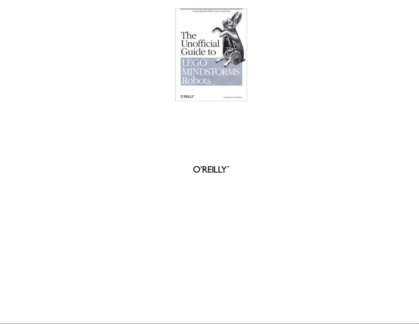
Figure 1-1 illustrates the basic setup. Building a robot using MINDSTORMS consists of four steps:
1. Build the robot's body.
2. Write a program for the robot using software tools on your PC.
3. Download the program to the robot.
4. Run the program.
This is only a sketch of the process, of course; it's likely you'll repeat the steps many times as you gradually improve the mechanical design and software of your robot.
You can create a program on your PC using the MINDSTORMS software. Then you need to download it to the RCX using the IR link. Once the program is downloaded, your robot is ready to go.
Is it a good deal? Yes. You could build a comparable setup by buying the pieces separately, but it would cost more and would not be nearly as easy to use.
Page 14
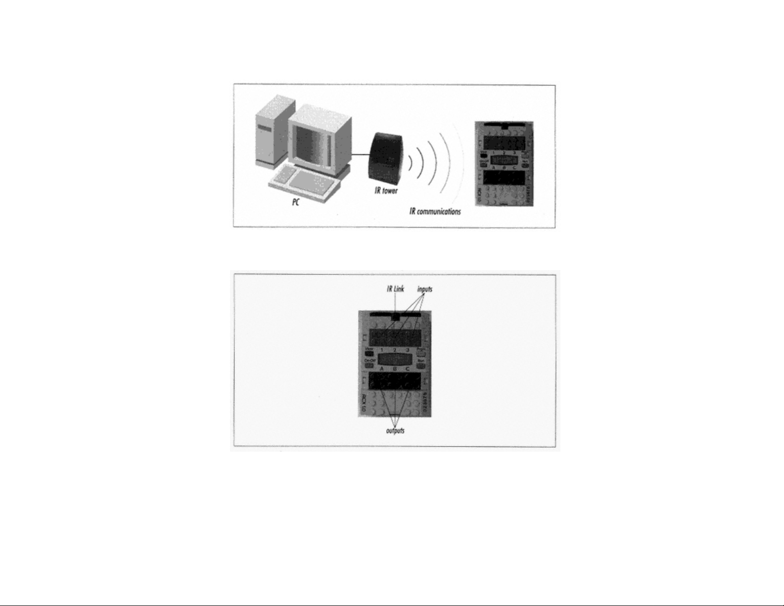
Meet the RCX
The RCX is a robot brain in the form of a bulky LEGO brick. Figure 1–2 shows a photograph of the top of the RCX.
Figure 1-1.
Basic MINDSTORMS setup
Page 8
Figure 1-2.
The RCX, a robot brain
The RCX is a small computer with the following features:
outputs
Three output ports, labeled A, B, and C, are located near the center of the brick. The robot's actuators (motors or lights) can be attached to these ports.
inputs
Three input ports, labeled 1, 2, and 3, are provided. Various types of sensors can be attached to these ports to allow the RCX to find out about its environment.
Page 15

Page 9
screen
The RCX includes a small LCD screen. This screen displays helpful information such as sensor readings and output port settings.
sound
The RCX is capable of producing beeps of different frequencies.
front panel buttons
Four buttons are provided to control the RCX. You can select a program, start it, and stop it. You can also view the values of attached sensors or check the settings on output ports.
IR communications link
The RCX communicates with your PC through the IR (infrared) link, similar to that on a television remote control. It can also communicate with other RCXs through this link.
About the Software
The CD-ROM that comes with RIS contains a lot of software. Basically it can all be distilled down to three pieces:
documentation
The RIS software includes extension tutorials about setting up and programming the RCX. These include animations, movies, and detailed, step-by-step instructions. When you first begin using
the software, it is in guided mode, which means the software tells you what to do next. This is a good way to get used to the software and the RCX.
programming environment
The RIS software includes an environment you can use to write programs that will run on the RCX. In the computer world, this technique is called cross-compiling, meaning you write a program
on one computer that you intend to run on another. In this case, you use your PC to write a program that will be run on the RCX. As you'll see, there are many ways to write programs for your
RCX; the official environment that comes with RIS is only one of them. This book will introduce you to four powerful alternate programming environments.
program downloader
Once you've written a program for the RCX, you need to know how to run it. The RIS software includes a program downloader for this purpose. The program downloader is a special application
that runs on your PC. It knows how to transmit your robot programs into the RCX using the IR link.
What About MacOS and Linux?
Currently, the software that comes with RIS runs only on Windows. If you have MacOS or
Linux, however, you can still program your robots, just not with the official software. The
best option, at least to get started, is NQC, which is described in Chapter 4. Appendix A,
Finding Parts and Programming Environments, lists the different packages that are
available. If you really want visualstyle programming (like RCX Code), you can purchase
ROBOLAB, which provides a similar (but more powerful) environment on MacOS.
There's one final wrinkle if you want to program from MacOS: you'll need a suitable cable.
The following web page describes the issues of programming the RCX from MacOS,
including cables:
http://www.enteract.com/~dbaum/lego/macmind/index.html.
You can purchase a Macintosh IR tower cable from Pitsco LEGO DACTA for $15US. See
Appendix A for details.
Expansion Sets
Page 10
Page 16

Aside from the basic RIS set, the MINDSTORMS product line also includes expansion sets. These sets provide additional parts and software to supplement the RIS set. Two such sets exist, each
selling for about $50US :
Extreme Creatures
This set comes with about 150 LEGO pieces and is designed so you can add decorative jaws and claws to your robots. It includes a light that can be attached to one of the output ports of the RCX.
Robosports
This expansion set includes about 90 LEGO pieces, two balls, two pucks, and an additional motor. It's oriented towards robots that can play different sports.
A third expansion set, Exploration Mars, should be released sometime in 1999.
Among LEGO enthusiasts, the consensus is that the expansion sets are not as good a value as the RIS set itself. If you're looking for extra pieces, it might be better to buy a LEGO TECHNIC set
instead. If you're looking for additional sensors and motors, by themselves, there are other ways to get these. See Appendix A, Finding Parts and Programming Environments, for details.
Other Sets
RIS isn't the only game in town. In 1999, two new MINDSTORMS sets were released: the Droid Developer Kit and the Robotics Discovery Set. Both sets are
Page 11
based on the same technology as RIS. They have more limited capabilities than RIS with the intent of making them easier to use.
What Now?
Now that you have some background in mobile robots and LEGO MINDSTORMS, what should you do? Play.
Read the manuals, follow the instructions on the MINDSTORMS CD, and have fun with your new toy. When you're thirsty for more, come back and read the rest of this book. It will tell you
everything you need to know to push your MINDSTORMS set as far as it can go.
Online Resources
One of the most exciting things about MINDSTORMS is the online community that supports it. On the one hand, LEGO's official MINDSTORMS site provides some interesting information as
well as a chance for RIS owners to exchange designs and ideas. But in the months since the release of MINDSTORMS, many unofficial sites have appeared. These cover a broad range of topics:
clever mechanical designs, novel sensors, alternate programming environments, even a new operating system for the RCX. I'll list references to online resources at the end of each chapter in this
book; my lists are also available online at
http://www.oreilly.com/catalog/Imstorms/. There's a lot of information out there.
LEGO MINDSTORMS
http://www.legomindstorms.com/
This is the official site of MINDSTORMS. It contains handy tips and mildly informative articles. If you own a MINDSTORMS RIS set, you can sign up for your own little corner of this web site,
where you can post pictures of your creations and even the programs that run them.
LEGO Worlds
http://www.lego.com/
This is the official site of The LEGO Group. It's a good place to go to browse through different product lines and to get a sense of the entire company's product offerings.
Robotics
http://www.lugnet.com/robotics/
LUGNET (the international fan-created LEGO Users Group Network) forms the hub of the online LEGO universe. LUGNET hosts many useful discussion groups; a whole hierarchy of them is
devoted to robotics. This URL will take you to the top level of the LEGO robotics discussion groups, which is further
Page 17

Page 12
subdivided into more specific interests. LUGNET is an outstanding, searchable resource.
Lego Mindstorms Internals
http://www.crynwr.com/lego-robotics/
This page, maintained by Russell Nelson, contains many fascinating nuggets of information about RIS and the things you can do with it.
RCX Internals
http://graphics.stanford.edu/~kekoa/rcx/
This page presents the results of Kekoa Proudfoot's reverse engineering efforts on the RCX, which enabled the development of interesting technologies like NQC. pbFORTH, and legOS. For hardcore geeks, this page is fascinating reading. Kekoa is, to quote Russell Nelson, a ''minor deity" in the online MINDSTORMS world.
LEGO on my mind: Roboworld
http://homepages.svc.fcj.hvu.nl/brok/legomind/robo/
This comprehensive unofficial site contains a helpful section that introduces MINDSTORMS RIS and its TECHNIC doppelgänger, CyberMaster.
LEGO MINDSTORMS WebRing
http://members.tripod.com/~ssncommunity/webrings/legoms_index.html
A web ring is a set of sites that are all linked to each other. You can traverse forward or backward through the entire ring if you wish, or visit sites in a random order. Browsing the
MINDSTORMS web ring is a good way to acquaint yourself with the MINDSTORMS online community.
LEGO MindStorms Gallery
http://member.nifty.ne.jp/mindstorms/
This Japanese web site, maintained by someone named Joe, includes photographs and descriptions of many, many different robots, including several flavors of walkers. The text is mostly in
Japanese, but the pictures are fascinating, even if you can't read the text.
Ben's Lego Creations
http://www.pobox.com/~benw/lego/
Ben Williamson is a very gifted mechanical designer. This visually clean web site details Ben's creations, including a working plotter, a treaded robot with a grabber arm, an intelligent truck, and
other pearls.
Lego
http://www.mop.no~simen/lego.htm
Simen Svale Skogsrud maintains this fascinating site. It contains, among other interesting things, a detailed description of a MINDSTORMS-based optical scanner.
Page 13
Lego
http://www.fischer-mellbin.com/Marcus/Lego/lego.html
This web site belongs to Marcus Fischer-Mellbin, a ten-year-old with a penchant for natural disasters. Along with other models, you'll find photographs and descriptions of a MINDSTORMSbased Tsunami and tornado.
The Epistemology and Learning Group
http://el.www.media.mit.edu/groups/el/
The Epistemology and Learning Group (E&L group) at MIT's prestigious Media Lab basically developed the RCX that is the centerpiece of MINDSTORMS. This web site provides an overview
of the E&L group and describes its aspirations and current projects.
Page 18

The MIT Programmable Brick
http://el.www.media.mit.edu/groups/el/projects/programmable-brick/
The MIT Programmable Brick is the forerunner of the RCX. Looking through this site is like leafing through the RCX's family photograph album.
Crickets: Tiny Computers for Big Ideas
http://fredm.
If MINDSTORMS robots aren't small enough for you, take a look at Crickets, another project from the fine people at MIT. Hardly larger than a nine-volt battery, Crickets are a very tiny mobile
robot platform. Crickets are not publically available, but this site can give you the inspiration to build your own tiny robots.
What's New at Eureka
http://www.eureka.com/whatsnew/robotvac.htm
I'm not the only one who doesn't want to vacuum the floor. This page at Eureka describes the Eureka Robot Vac, a kind of concept car in the world of vacuum cleaners. Supposedly it will navigate
through a room, around obstacles and over electrical cords, vacuuming as it goes. My favorite part: "Switch on the robot vac and you'll hear a robotic tone" What's a robotic tone?
www.media.mit.edu/people/fredm/projects/cricket/
Page 14
2 Hank, the Bumper Tank
In this chapter:
• About the Building
Instructions
• Building Instructions
• A Simple Program
• Wheels
• Bumpers and Feelers
• Gears
• Multitasking
• Online Resources
Hank is the first robot we'll be building. He is a friendly robot who explores the floor of a room. Whenever he bumps into an obstacle, like a chair leg or a shoe, he backs up, turns away from the
obstacle, and goes forward again. This chapter includes complete building and programming instructions so that you can build Hank yourself. Hank is a fairly simple robot that will serve as a good
jumping-off point to discuss:
Page 19
• Various means of locomotion
• Bumper design
• The use of gears
• Motors
• Software multitasking
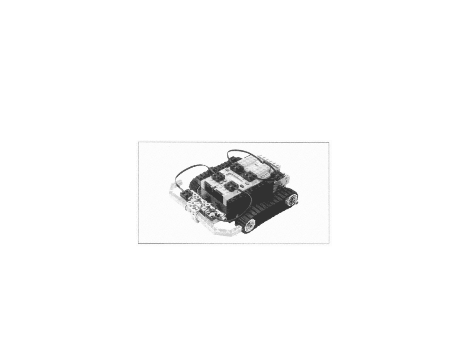
Figure 2-1 shows a picture of the completed robot. I suggest you begin by building and programming Hank. Let him run around your floor for a while. Then come back and read the rest of the
chapter, where I'll talk about some of Hank's interesting features.
About the Building Instructions
The building instructions for the robots in this book are comprised of pictures, with a little bit of explanation here and there. Each step shows you the parts you need as well as how they fit
together. There are, however, some names with which you should be familiar, so that I don't end up describing everything as a ''doo-hickey" or a "little gray thingy." The parts you need to know
are beams, plates, shafts, gears, bushings, and wire bricks.
Page 15
Figure 2-1.
Hank, a friendly robot
Beams, plates, and shafts are characterized by their length. For beams, at least, this corresponds to how many studs (bumps) are on the beam. Figure 2-2 shows a photograph of some beams, plates,
and shafts with their corresponding lengths. The "u" stands for "units."
Page 20
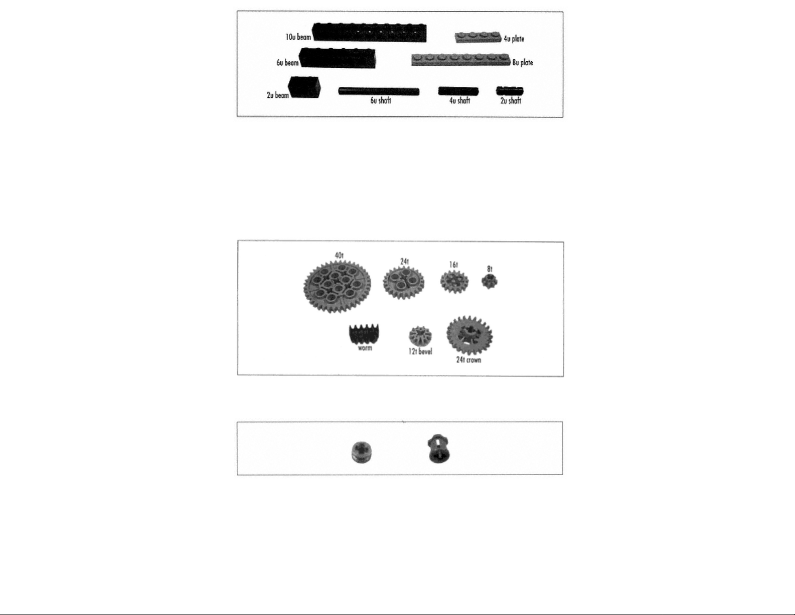
Figure 2-2.
Some beams, plates, and shafts and their lengths
Gears, for the most part, are described by the number of teeth they have. A 24t gear, for example, has 24 teeth. (The "t" stands for "teeth.") Figure 2-3 shows a photograph of the various types of
gears that come with the RIS kit.
There are two types of bushings in the RIS kit: regular and half-size. Both fit on shafts and are used for securing a shaft in place or for spacing. Figure 2-4 shows the bushings.
Page 16
Figure 2-3.
Gears
Figure 2-4.
Full and half-size bushings
Finally, the term wire brick refers to the part shown in Figure 2-5. This piece is used to make an electrical connection between a sensor or motor and the RCX.
Page 21
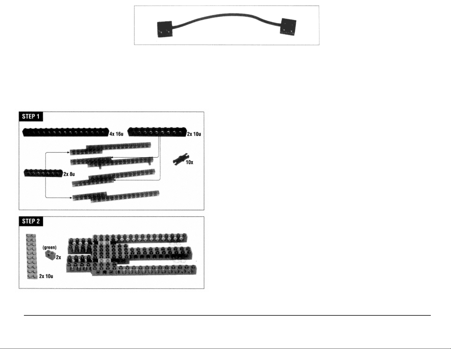
Figure 2-5.
A wire brick
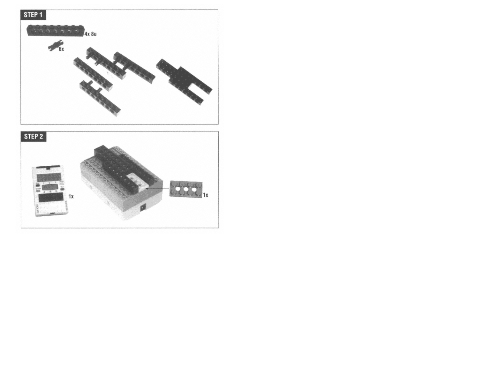
Building Instructions∗
Create Hank's main chassis as shown in the next two steps; this will hold the RCX, the motors, and the bumpers.
Page 17
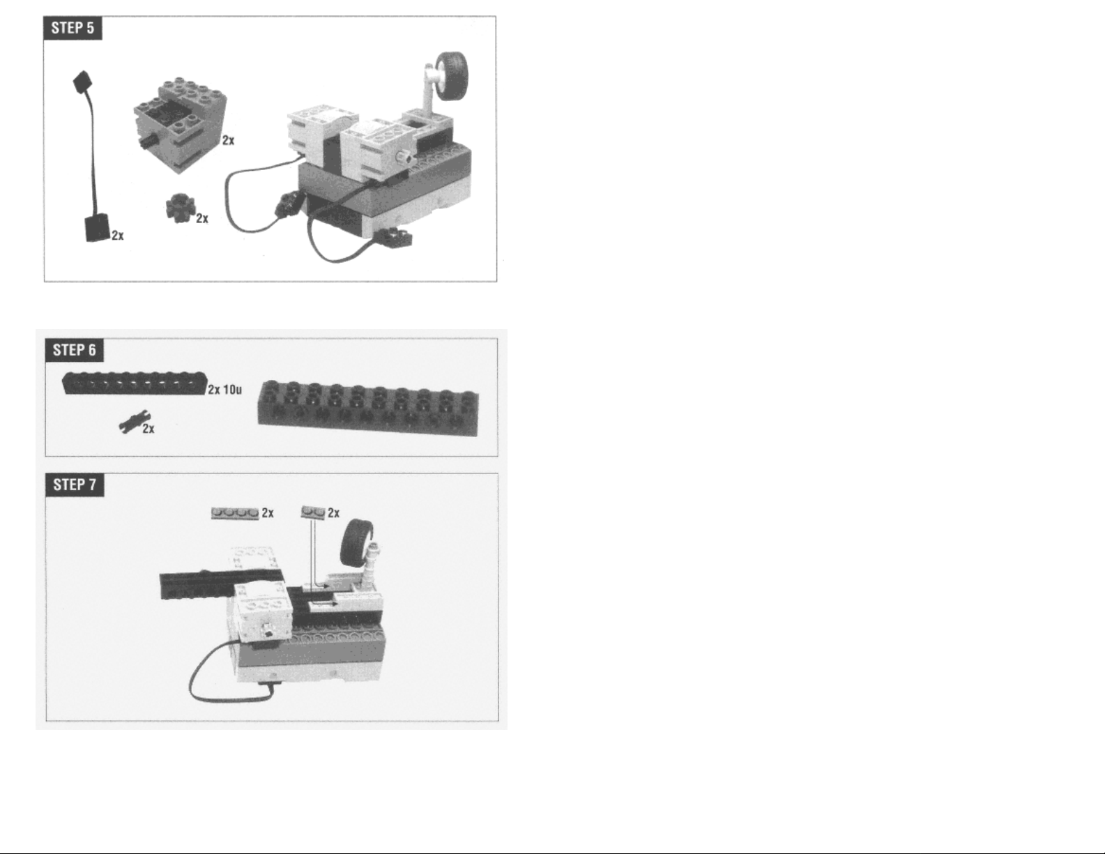
Attach the shafts as shown. Hank's treads will be mounted on these shafts. The front pair do not rotate, while the rear pair should. Don't push the front pair all the way in; you'll need to fit the tread
wheel and another bushing on the end.
∗ The parts included with RIS 1.5 are slightly different than those in RIS 1.0. If you're building Hank using RIS 1.5, you should use two bushings instead of the green pieces in Step 2.
Page 22
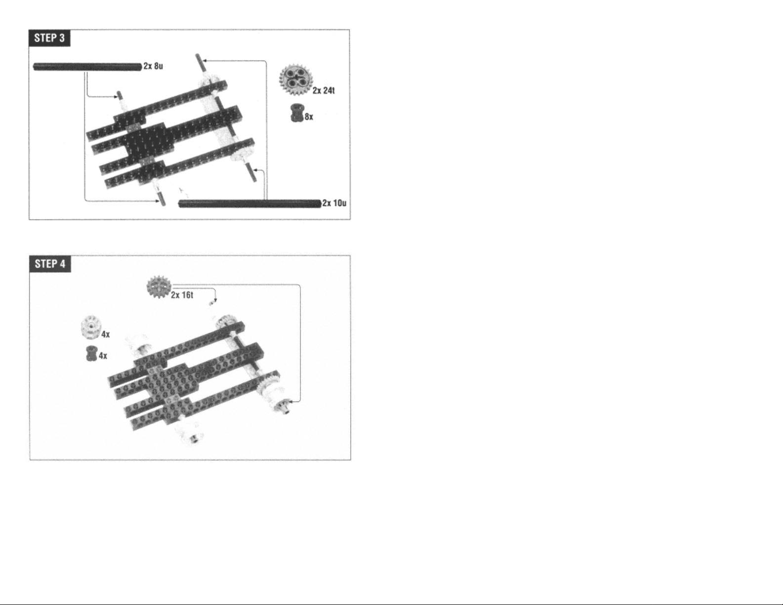
The back tread wheels are anchored to the shafts with the 16t gears.
Page 18
Page 23
Page 19
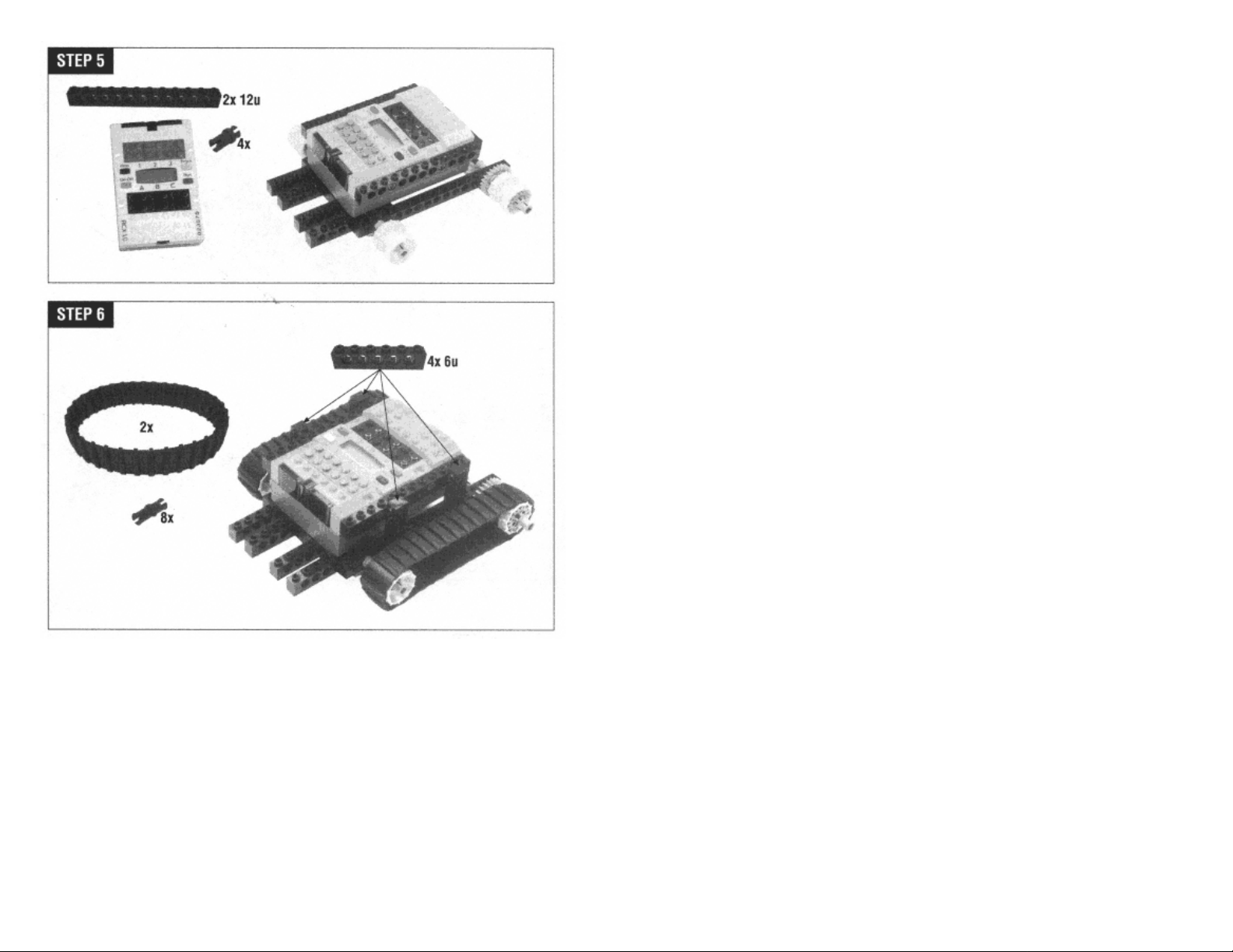
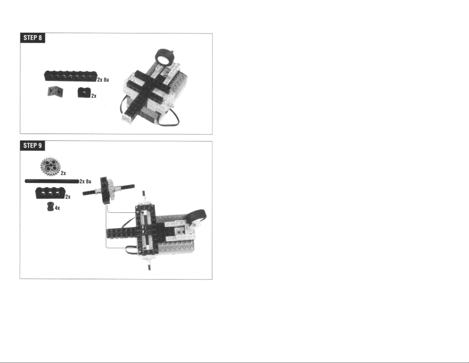
Next, start building support for the drive motors.
Page 20
Page 24
Place the wire bricks on the motors, then anchor them down with the yellow plates. The wires themselves will fit into the grooves on the top of the motors.
Page 21
Page 25
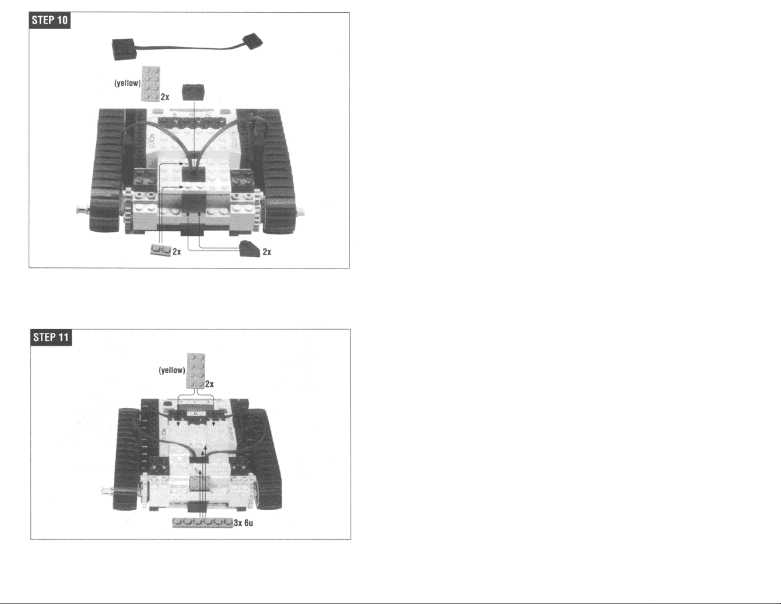
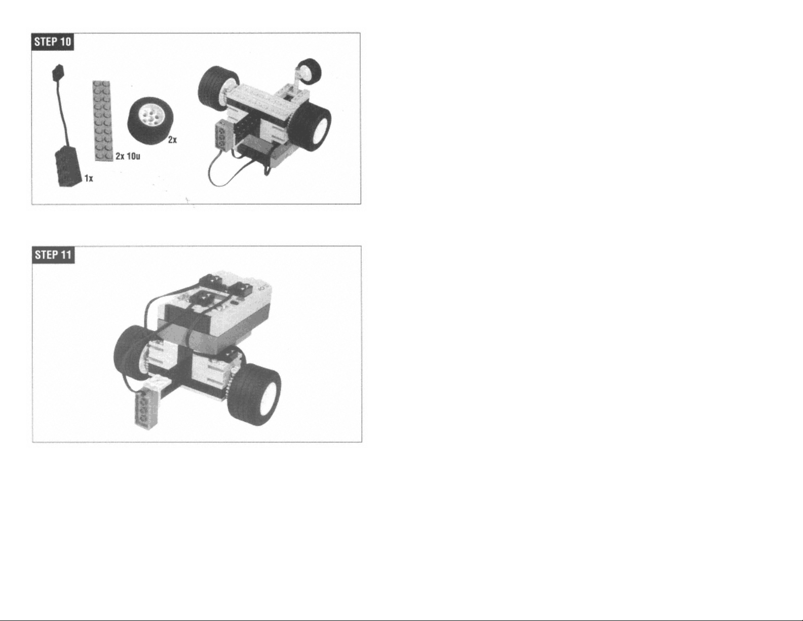
Attach the motor wires to output A and output C.
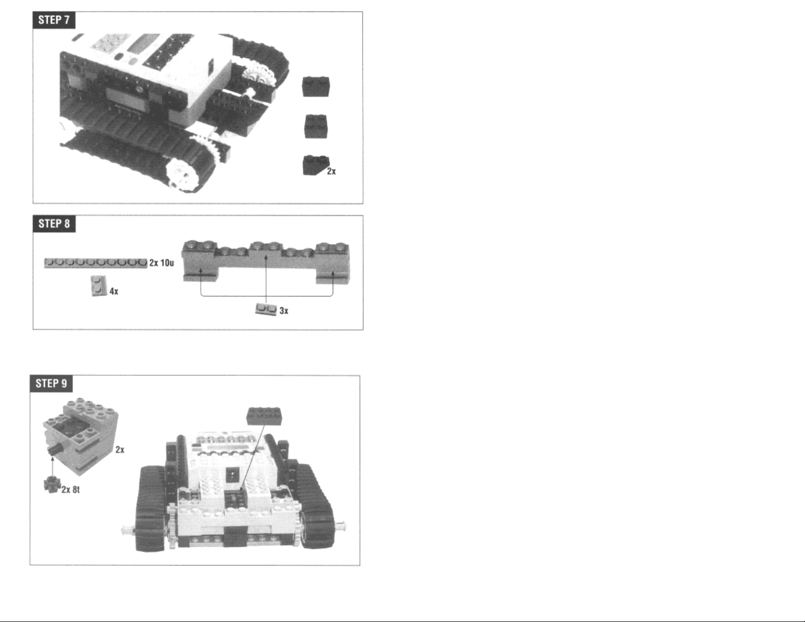
Next, build the platform for the front bumpers.
Page 22
Page 26

The touch sensors are attached only by the shaft that runs through them.
Page 23
Page 27
Hank's left bumper is next. A light touch on the bumper pushes the touch sensor.
Hank's right bumper works exactly the same way.
Page 24
Page 28

The bushings are pushed onto the plate in the next step. Note that the bushings are not symmetrical; one side will push into the plate, and the other side won't.
Page 25
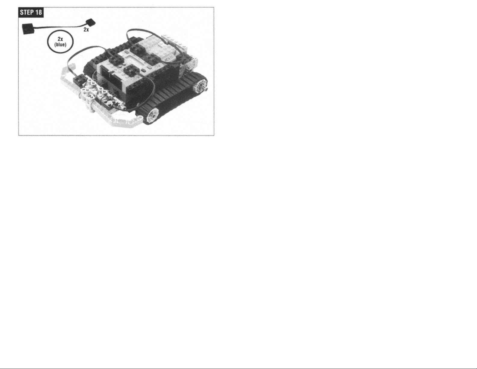
Finish Hank by attaching the bumper touch sensors to input 1 and input 3. Slide the blue rubber bands onto the bumpers and anchor them to the bushings from the last step. The rubber bands keep
the bumpers from swinging forward.
Page 29
A Simple Program
Now that you've built a robot, you need a program to make it work. Hank's mission in life is to explore the world.
Page 26
His basic program works something like this:
go forward
if I've bumped into something
back up
turn away from the obstacle
start over
This program translates pretty simply into the RIS programming environment, as shown in Figure 2-6. The program assumes that the two motors are attached to outputs A and C, while the touch
sensors should be attached to inputs 1 and 3.
Page 30
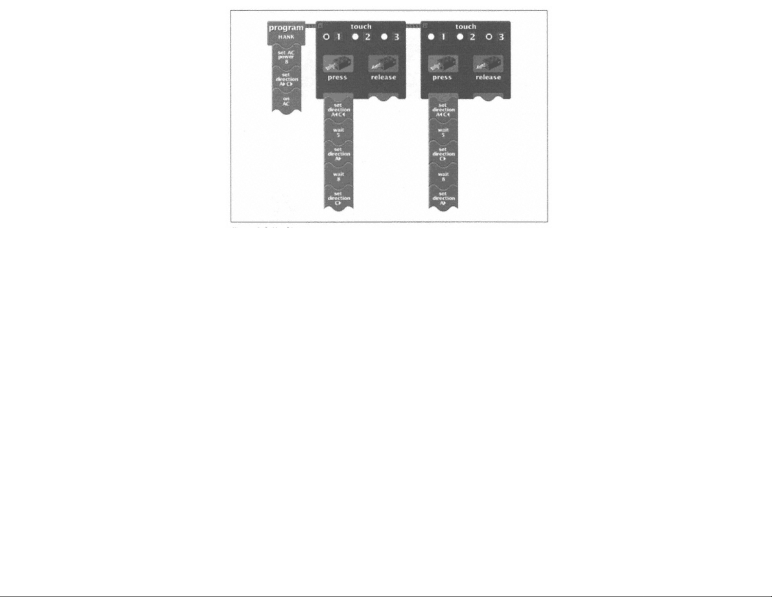
Figure 2-6.
Hank's program
To create this program, enter the RIS software. Choose Program RCX from the main menu, then RCX Code. Use the menus on the left side of the screen to click and drag out different program
''blocks." If you're not familiar with this process, you should probably go back and take a look at LEGO's official documentation, either the printed material or the computer-based tutorial.
Once you have created the program, download it and run it. (You can download or save a program by right-clicking on the main program block.) If everything goes right. Hank should amble
around on your floor, trying to avoid things he bumps into. If you have pets, this would be a good time to introduce them to your new toy.
Page 27
Hank is a pretty simple robot, but you still may run into trouble:
• If your robot spins in place or goes backward instead of forward, you may need to adjust the wires that connect the motors to the outputs. Remove one of the wires and turn it 180° around. This
will reverse the direction of the attached motor. If the robot is moving backward instead of forward, turn both wires around.
• Hank may not run well on very thick carpet, because there's not much space between the bottom of the body and the floor.
Once you've got things running smoothly, read on. I'll describe Hank's most interesting features in the rest of this chapter.
Locomotion
Hank gets around in the world on a pair of treads, like a tank or a bulldozer. This is just one approach to the general problem of locomotion. Different designs have different merits—you should
choose a locomotion method based on what kind of terrain you're expecting your robot to encounter.
Treads
Hank's treads have some interesting properties. Foremost among these is zero turning radius, which is a fancy way of saying that a treaded robot can turn around in one place. (I'll explain why it's
a radius a little later.) Each tread is driven by one of the motors, so all you need to do to turn is move the treads in opposite directions at the same speed. This turning, however, is accomplished
with a good deal of friction. Both treads slip on the driving surface. Tanks in Veteran's Day parades can really chew up roads this way.
The large surface of the treads is one of their other assets. Treads are good for driving on jagged or slippery terrain. Hank should do pretty well driving over uneven obstacles, like a small pile of
LEGO bricks.
Page 31

Differential Drive
Treads are a special kind of differential drive, in which two wheels are each driven by a motor. The wheels are mounted on either side of the robot, like the treads. Figure 2-7 shows a top view of
such a robot.
Independent drive wheels behave a lot like treads. If you run them both forward at the same speed, the robot moves forward. Run the drive wheels in opposite directions, and the robot will spin in
place. This design also exhibits zero turning radius, but without the slipping of the treads.
Page 28
Figure 2-7.
Independent drive wheels
Zero turning radius is nice in robots that measure how far each wheel travels. (You could do this using rotation sensors.) Once you know how far each wheel on a differential drive robot has
traveled, you can calculate with a fair degree of accuracy the location of the robot relative to its starting point.
The idler wheels don't drive or steer the robot. They exist to keep the robot from tipping over. They can turn freely to point in whatever direction the rest of the robot is moving. Figure 2-8 shows a
typical idler wheel.
Figure 2-8.
An idler wheel
Page 32

Page 29
Cars
Modern automobiles demonstrate another popular approach to locomotion. Cars have four wheels, two in front and two in back. The back wheels drive the robot (or car) forward and reverse,
while the front wheels are used for steering. Figure 2-9 shows how this looks.
Figure 2-9.
Car-style locomotion
Rear-wheel drive is simpler because it decouples the drive mechanism from the steering mechanism. But you could obviously build front-wheel drive robots, with enough parts. Whichever system
you choose, this design does not have a zero turning radius. (You can't spin in place in your car.) The term turning radius comes from what happens when a car-style robot drives in circles, as
shown in Figure 2-10.
Figure 2-10.
Turning radius of a car
This type of design can be difficult to maneuver, as you'll know if you've ever tried to parallel park a car. The other subtlety of this design involves the back drive wheels. When the car turns, the
back wheels must turn at different speeds. Consider Figure 2-10 again—the inside back wheel has a smaller distance to go than the outside wheel.
Page 33

Page 30
This means that you can't simply connect the two drive wheels with a shaft and hook it up to a motor. You need something trickier, called a differential (not the same as differential drive).
A simple variation on the car design is the tricycle design. In this design, a single wheel, instead of a pair, is used for steering.
Exotic Drives
There are three other interesting drives that should be mentioned. The first of these is synchro drive. In this scheme, the robot has three or more identical wheels. Each of the wheels pivots on its
vertical center. All of the wheels point in the same direction. as shown in Figure 2-11.
Figure 2-11.
Synchro drive
To turn, the robot swivels the wheels to point in a new direction. This has the interesting side effect that the robot can change direction even though its body stays oriented the same. This property
could be useful for robots that need to communicate with the computer over the IR link. The key to building synchro drive robots is a piece called a large turntable. You can order these pieces
from Pitsco LEGO DACTA; see Appendix A, Finding Parts and Programming Environments, for details.
The tri-star wheel is another interesting idea. Figure 2-12 shows a side view of a tri-star robot and a close-up of the wheel assembly.
Figure 2-12.
Side view of the tri-star design
Page 31
Each wheel assembly is actually composed of three wheels arranged in a triangular fashion. The robot drives these wheels to move. When a large obstacle (like a step) is encountered, the entire
wheel assembly rolls on its center axis. In essence, the entire wheel assembly acts like a large triangular wheel. This large wheel size enables the tri-star design to drive over large obstacles.
Killough's platform is an interesting variation on the wheels-within-a-wheel concept. It's really too exotic to describe here; the "Online Resources" lists two web pages that contain photographs and
diagrams of this platform.
Bumpers and Feelers
Hank uses the touch sensors to figure out when he bumps into something. But it's not really enough to put a touch sensor just on the front of your robot, because then it could be activated only in
one specific spot. Instead, Hank uses a pair of bumpers to detect touches across the entire front of the robot.
The idea of a bumper is to make a large area sensitive to touch so that the robot can detect collisions with a wide variety of objects—chair legs, walls, pets, rocks, trees, and so forth.
Page 34

Hank uses bumpers that rest lightly against the touch sensors. When the bumper is pressed anywhere along its length, the touch sensor is then also pressed. A slightly different approach is to make
a bumper that is held tightly against the sensor. When the bumper collides with something, the sensor actually turns off instead of on.
The trick with bumpers is to make them sensitive but not too sensitive. The bumper needs to trigger the touch sensor when the robot bumps into something. On the other hand, it should not trigger
the touch sensor when the robot starts or stops moving abruptly or when it's driving over a bumpy surface.
Gears
Gears are clever mechanical devices that can be used to trade speed for power or to translate motion from one axis to another. A gear, in essence, is a disk with teeth on its edge. It has a space in its
center where you can put a shaft. Gears have three primary purposes:
1. You can trade speed for power by using a small gear to drive a larger gear. The shaft on the larger gear will turn more slowly but more powerfully than the shaft on the smaller gear.
2. The opposite effect—trading power for speed—occurs if you use a large gear to drive a smaller gear. The shaft on the smaller gear will turn faster than the one on the larger gear, but with less
power.
Page 32
3. You can use gears to transfer motion from one axis to another. The gears in Hank's body transfer motion from the motors to the drive axles of the treads, as shown in Figure 2-13.
Figure 2-13.
Using gears to transfer motion
The Palette of LEGO Gears
LEGO offers an impressive array of gears. The LEGO community has adopted names for these gears, which I will use throughout this book. Refer back to Figure 2-3; it shows the gears that come
with RIS and their names. For the most part, gears are named based on the number of teeth they have. The 40t gear, for example, has 40 teeth. The number of teeth is directly proportional to the
gear's radius, so the 24t gear has a radius exactly three times as large as the 8t gear.
Specialty Gears
You're probably comfortable with the 8t, 16t, 24t, and 40t gears. They can be put together to transfer rotational motion from one axis to another. In particular, these gears are used to transfer
motion between parallel axes.
The gears in the bottom row of Figure 2-3 can be used to transfer motion between perpendicular axes. Two of these are bevel and crown gears.
The worm gear is a real character, for two reasons:
1. While the other gears attach firmly to the shaft, the worm gear can slide freely along the shaft. If you want it to stay in one place, you'll need to anchor it down somehow.
2. The worm gear really works only one way: you drive the worm gear, and it drives another gear. There's no way to turn the other gear and have it translate to motion in the worm gear.
Page 35

Do the Math
The mathematics of gears can be described in a high school physics class. The two
important equations have to do with torque and angular velocity.
Here's the equation for torque, which is a measure of the power in a turning shaft:
In this case, τ is torque, F is force, and r is the distance from the center of the rotation to the
point where the force is applied. For a gear, this is the distance from the center (where the
shaft runs through) to the teeth. This is the same as the radius of the gear. Suppose, then,
that you have an 8t gear driving a 24t gear.
The equation for the torque of the 8t gear's shaft is this:
The radius of the 24t gear is exactly three times the radius of the 8t gear. The force is the
same where the teeth of the two gears meet. Therefore, the torque on the shaft on the 24t
gear is exactly three times the torque on the 8t gear's shaft:
Page 33
Angular velocity is the measure of how fast a shaft rotates. The angular velocity of a shaft
can be expressed in terms of the velocity of a point on the gear as follows:
Here, ω is the angular velocity, v is the velocity of the point on the gear, and r is the
distance between the point and the center of the gear. For the example I just described (an
8t gear driving a 24t gear), the angular velocity of the 24t gear is exactly one third of the
angular velocity of the 8t gear. You can figure this out because the velocities of the gear
teeth must be the same:
In general, then, it's easy to figure out the ratios of torque and angular velocity for two
mating gears, just by figuring out the ratios of gear teeth. If you use an 8t gear to drive a 40t
gear, you'll end up with fives times the torque and one fifth the angular velocity.
Page 36

Page 34
Of Geared and Ungeared Motors
There's one more topic related to gears that's important. Most electric motors turn too fast and with too little power to be useful. Gears are usually used to swap speed for power until a good
balance is achieved. This process is called gearing down or gear reduction.
The motors that come with RIS are internally geared, which means that the motor case actually contains an electric motor and some number of gears. The output shaft is already adjusted to turn at
a reasonable speed with a reasonable amount of power. This means you can attach wheels directly to these motors to drive your robot around.
The LEGO group makes four different kinds of motors that can be driven from the outputs of the RCX:
standard motor
This has been the standard motor of the LEGO TECHNIC line for many years. It is an ungeared motor, which means its output shaft rotates very rapidly, with little power, when electricity is
applied. To do any useful work with it, you'll probably have to use gears to reduce its output speed.
micro motor
This is a tiny motor with low speed and low power. You probably can't use this motor to move your robot, but it could be useful for lighter tasks. It's harder to find than the other motors.
geared motor
Two of these motors come with the MINDSTORMS RIS kit. They are internally geared so that the output shaft has enough power to drive your robot around. They are more efficient than the
standard motor. The geared motor is shown in Figure 2-14.
Figure 2-14.
The geared motor
train motor
LEGO sells an entire line of train sets. The train motor can be controlled by your RCX; as a matter of fact, you can make an "intelligent" train by mounting the RCX in one of the cars.
For a Rainy Day
To see exactly how efficient the geared motors are, try this experiment. Use one of the
"wire bricks" to attach two motors to each other. When you turn the shaft of one motor, the
other motor's shaft will turn simultaneously. What's going on here? Just as you can supply
power to make the motor turn, turning the motor with your hand generates power. This
power is transferred to the other motor, where it's converted back to the movement of the
shaft.
Page 35
Page 37

Of course, you haven't actually built anything useful. But it's a good demonstration of the
efficiency of these motors. The shaft on the second motor turns at nearly the same speed as
the first motor, which means very little energy is lost in converting mechanical energy to
electrical energy and vice versa.
If you have a choice of motors, you'll probably always use a geared motor. It is more efficient, more convenient, and less bulky than the standard motor. The micro motor is hard to find and not
strong enough for most tasks.
How can you get more motors? RIS comes with two motors, but there are three outputs on the RCX. You can get another motor in the RoboSports expansion set, but it'll cost you $50.
You can order extra motors from the LEGO Shop-at-Home service, one of The LEGO Group's best-kept secrets. This service is available in the United States at (800) 835-4386. They have a
variety of sets and spare parts—the item numbers for the motors are as follows:
• Standard motor, item 5114
• Micro motor, item 5119
• Geared motor, item 5225
• Train motor, item 5300
You can also order the first three motors from Pitsco LEGO DACTA: (800) 362-4308.
For more information on extra parts and ordering, see Appendix A.
Page 36
Multitasking
Don't be fooled by the simplicity of the RIS programming environment—it hides some pretty messy details. Hank's simple program demonstrates a powerful feature of the RCX software:
multitasking. This is a term from the computer world—it just means that the RCX can do more than one thing at a time. Each of the two instruction sequences hanging off the touch sensor
watchers is a separate task, and they can actually execute at the same time. To see this in action, touch one of Hank's bumpers to trigger the first task, then touch the other bumper shortly
afterward. (To really see this effect, you could try putting in longer delay times in Hank's program.)
The sensor watchers in RCX Code exhibit another interesting property. If you trigger a sensor watcher, the code for that watcher begins executing. If you trigger the same sensor watcher again,
while the watcher code is still executing, the watcher code starts over again from the beginning.
The relationship between the programs you create in RCX Code and the tasks that run on the RCX is not always clear. Tasks and subroutines are declared explicitly in NQC, one of the alternate
programming environments for the RCX. See Chapter 4, Not Quite C, for details.
Figure 2-15 shows how the multitasking nature of the RCX can get you into trouble. The figure shows an alternate program for Hank. At first glance, it makes sense. The main program starts
Hank moving forward. When one of the bumpers is touched, the robot backs up, waits, turns, waits, and starts going forward.
Page 38

Figure 2-15.
A slightly dangerous program
Page 37
A serious problem occurs if the same bumper is quickly hit twice. Suppose the bumper on input 1 is hit once. It begins executing its sensor watcher code by reversing the direction of the motors.
The robot travels backwards for half a second, then output A reverses direction and the robot spins in place. Suppose, now, that the bumper on input 1 is triggered again, before output C's direction
is reversed again. The sensor watcher routine will begin again, reversing the direction of both the motors. Hank, therefore, will begin spinning the other direction instead of moving backwards.
Then output A's direction reverses, and the robot moves forward. Finally, output C's direction reverses, and the robot spins in place again, instead of moving forward.
There are two solutions to this problem. First, you can be more explicit about controlling outputs. Instead of just reversing the output directions in the sensor watcher routines, you could
specifically set the directions and turn on the motors. This technique is shown in Hank's first program, in Figure 2-6. It doesn't matter if the sensor watchers are interrupted before they finish,
because the directions of the motors are always set explicitly. The other solution is to structure your program differently. If your sensor watchers don't have any delays built into them, for example,
they will be much less likely to be interrupted.
Online Resources
The Art of LEGO Design
ftp://cherupakha.media.mit.edu/pub/people/fredm/artoflego.pdf
This is an outstanding paper about building with LEGO parts. It includes helpful tips on making strong structures and using gears. The paper is written by Fred Martin, one of the people at the
MIT Media Lab whose programmable brick work formed the basis of the RCX. I highly recommend this paper, especially if you are having trouble getting things to fit together.
Fred's 6.270 Home Page
http://lcs.
www.media.mit.edu/people/fredm/projects/6270/
For a deeper treatment of many aspects of small mobile robotics, read the course guide for MIT's famous 6.270 class. In this class, students build robots from the ground up. The 6.270 Robot
Builder's Guide was written by Fred Martin; it is a real bonanza of information and advice.
Doug's LEGO Technic Tri-Star Wheel ATV and Robotics page
http://www.net-info.com/~dcarlson/
Doug Carlson's fascinating page is full of pictures of his implementations of the tri-star design, synchro drive, and the Killough platform. For sheer mechanical finesse, this page is hard to beat.
Page 39

Page 38
Killough's mobile robot platform
http://carol.wins.uva.nl/~leo/lego/killough.html
This part of Leo Dorst's acclaimed site gives some background and explanation of the Killough platform.
Synchronicity
http://members.xoom.com/jknudsen/Synchronicity/Synchronicity.html
This page has photographs of my own synchro drive robot, which has three wheels and a compact design.
Pitsco LEGO DACTA
http://www.pitsco-legodacta.com/
This is the official home page of Pitsco LEGO DACTA. Many of the interesting things that Pitsco LEGO DACTA sells are not listed online, but you can call and order a catalog. Make sure you
get the LEGO DACTA catalog, as Pitsco has an entirely different catalog that doesn't have anything to do with LEGO. This is the place to order the Robolab software that allows you to program
your RCX from a Macintosh.
Dacta Spares from Pitsco
http://www.ee.nmt.edu/~jmathis/dacta.html
This unofficial site contains images of some of the interesting pages in the Pitsco LEGO DACTA catalog, including the pages with the motors and sensors.
LEGO Motors
http://www.enteract.com/~dbaum/lego/motors.html
This page contains a concise description of the three kinds of motors.
3 Trusty, a Line Follower
In this chapter:
Building Instructions
Some Tricky Programming
The Light Sensor
Idler Wheels
Using Two Light Sensors
Online Resources
Page 39
Page 40

In this chapter, you'll build Trusty, a simple robot that exhibits a behavior called line following. This means that Trusty, shown in Figure 3-1, can drive along a sort of ''track" defined by a thick
black line on the floor. Your RIS kit includes a "Test Pad," which is simply a large piece of white paper with some black lines and other marks on it. Trusty will follow the large black oval on this
paper faithfully until he runs out of battery power.
Figure 3-1.
Trusty, a line follower
As you can see in Figure 3-1, Trusty's main feature is a downward pointing light sensor. This sensor is the key to line following. The light sensor can distinguish between the white background of
the Test Pad and the black line drawn on it. As
you'll discover, this feature doesn't make line following easy to program; but it does make it possible.
Building Instructions
Page 40
Page 41
Page 41
Page 42

In Step 4, make sure the top bushing allows the idler wheel to rotate freely by putting the round side next to the plate. If you put it on the other way, the idler wheel will be locked in place.
Be sure to attach the wire bricks to the motors before putting them on Trusty.
Page 42
Page 43
Next, build the support for the light sensor.
Page 44
The 2u beams between the motors will hold the ends of the drive shafts. Make sure that you can see the holes.
Page 43
Page 45
Flip the robot over and attach the wires as shown. The motors are attached to output A and output C, while the light sensor is attached to input 2.
Page 44
Some Tricky Programming
It's surprisingly hard to convince our robot to follow a black line on the floor. (A lot of things in mobile robotics are surprisingly hard, as we discussed in Chapter 1, Robotics and MINDSTORMS.)
The simplest way to describe the program is this:
Page 46

Page 45
if I'm on the line, go straight forward
if I'm off the line, find the line and start over
It's the "find the line" part that's difficult. When Trusty's light sensor goes off the black line, Trusty has no way of knowing if he's on the right or the left side of the line. Ideally, Trusty would turn
back to the line and start going straight again. He would proceed in a zigzag fashion along the line.
State
Even if Trusty doesn't know which side of the line he's on, he can make a pretty good guess. If he knows he drove off the left side of the line last time, it's a pretty good bet he'll drive off the right
side the next time. Figure 3-2 shows a likely path as Trusty tries to stay on the line.
Figure 3-2.
Trusty zigzags along the black line
With this in mind, Trusty's algorithm can be more specific:
if I'm on the line, go straight forward
if I'm off the line {
turn back the opposite direction from the way I turned last time
if I still don't find the line, turn farther back the other direction
}
Another way of looking at this is to say that Trusty now has two possible states:
1. Just turned left (turn right next)
2. Just turned right (turn left next)
By keeping track of this state, Trusty can figure out the best way to turn the next time he drives off the black line.
Could I Please Have a Variable?
Some kind of variable is needed if Trusty is to keep track of his state. Said another way, Trusty needs some kind of memory to remember which way he last turned. This highlights one of the weak
points of RCX Code (the RIS programming environment), its lack of variables.
Page 47

Page 46
The environment does provide a counter, which we'll use in lieu of a variable to hold the turning direction. Although you can't assign values directly to the counter, you can do two things: reset it
to zero and add one to it. Trusty will use just two values, 0 and 1, to mean turn left and turn right, respectively.
Coping with Failure
Our basic assumption about Trusty is that he will drive off the black line on alternating sides. But this probably won't really happen all the time, particularly if the black line has curves in it. What
Trusty needs is some way to figure out if he's turning the wrong way, away from the line instead of toward it. For this purpose, we'll use a timer. If Trusty doesn't find the line within a certain time
interval, we'll have him switch state and turn back the other way.
The real world is a very challenging place. You should always assume that bad things will happen to your robot and try to create a program that responds appropriately.
The Program
Figure 3-3 shows Trusty's basic program. It begins by setting the two motors to the forward direction at speed 4. The central decision point is the light sensor watcher. If the sensor sees the black
line, Trusty moves straight ahead. If the sensor sees the white background, then the program resets the timer and calls a subroutine called toggle. This subroutine turns the robot left or right,
alternating each time it is called.
Figure 3-3.
A top-level view of Trusty's software
Page 47
Use your own values for the thresholds of the light sensor watcher. The values shown in Figure 3-3 are calibrated to my particular light sensor and may not work
with yours.
The timer is used in case Trusty happens to turn the wrong way. Suppose, for example, that he runs off the right side of the black line twice in a row. The first time, he would turn left to find the
line again. The second time, however, he would turn right, away from the line. The timer is used to limit this behavior. If Trusty is turning and the timer goes off, then Trusty automatically turns
back the other way. Figure 3-4 shows the timer watcher, which calls the same toggle subroutine if the robot is still off the line.
You might be wondering why the timer counts for one half second. Why not three quarters of a second, or a full second? Remember that the timer keeps Trusty from turning around completely.
The timer value is based on observation—if Trusty is turning toward the line, he will find it within a half second. If he is turning away from the line, he can be pretty sure he's missed it after a half
second. A line-follower with a different mechanical design might need a different timer value.
Page 48
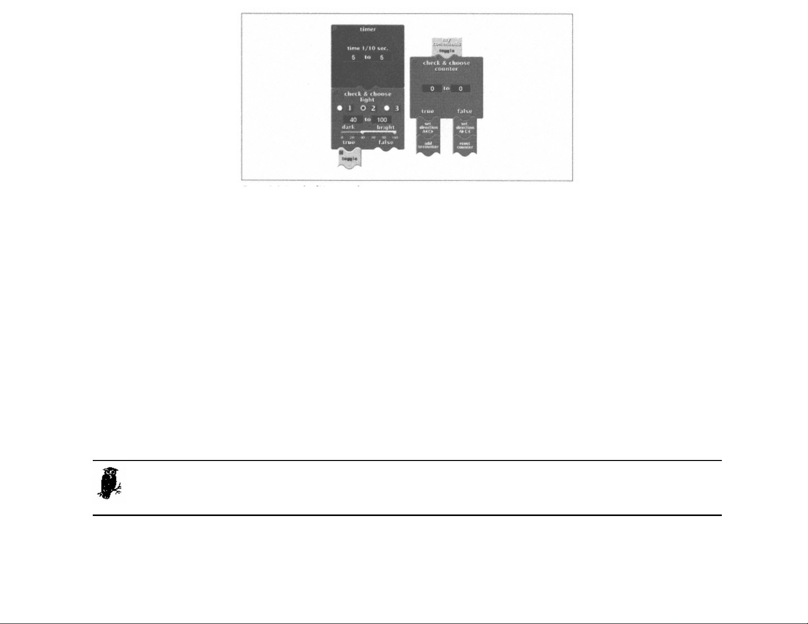
Figure 3-4.
Details of Trusty's software
Figure 3-4 also shows the toggle subroutine itself. All it does is examine the value of the counter. If it's 0, then the robot is set to turn left and the counter value is changed to 1. The next time
toggle is called, the robot turns right and the counter value is reset to 0. It's useful to have toggle as a subroutine because it is called from two places in Trusty's program.
Page 48
The Light Sensor
Working with the light sensor can be a little tricky. As measured by the RCX, the light sensor outputs a value from 0 (dark) to 100 (bright). However, the signal generated by the sensor has some
noise in it, which means the value jumps around unpredictably. To use a light sensor effectively, then, you need to figure out what the interesting values are and how to respond to them.
Testing Light Sensor Values
The easiest way to figure out what values your light sensor is generating is to use the RCX's View button. Press View repeatedly until a little arrow appears under the input with the sensor. The
RCX's screen should show the value of the sensor. You can place Trusty so the light sensor is over the line, and then observe the value. Now see what values you get when Trusty is off the line.
You should also try the green area of the Test Pad, and try all the measurements with the room both dark and light. This should give you a good feel for the values that are important.
The View button only works if the input is configured to measure a light sensor. To have the input configured correctly, you'll either have to run a program that sets it up or use the Test Panel, in
the RCX Code section of the RIS software. Click on the appropriate input until the light sensor appears. Then click on the Get Sensor Values button to get the current readings.
The choice of 35 and 40 in Trusty's program is based on my measurements; you may want to adjust these values for your specific conditions.
Don't expect to get the same readings from two different light sensors, even under the same conditions with the same RCX. Always test the values before you use
them in a program.
The Light Sensor Watcher
What's going on with that sensor watcher in Figure 3-3? It's actually two sensor watchers rolled into one. The following pseudocode shows how it works:
if the sensor value is in the range from 0 to 35 (but wasn't previously),
execute the "dark" commands
if the sensor value is in the range from 40 to 100 (but wasn't previously),
execute the "bright" commands
Page 49

Page 49
Figure 3-5 shows a hypothetical graph of the light sensor value, along with the times when the dark and bright commands will be executed. Nothing happens until the sensor value enters either the
dark or bright value ranges.
Figure 3-5.
The sensor watcher
Remember that the RCX runs some tasks at the same time. If the dark commands and bright commands both take a while to execute, it's possible they may overlap. If the light sensor reading gets
into the bright range and abruptly drops back into the dark range, the dark commands will start running while the bright commands are still in progress. You should be aware of this possibility and
structure your code to deal with it. In Trusty's program, the dark and bright commands both execute quickly so they won't overlap.
Ambient Light
You have to be careful with the light sensor; its value depends on all the light it receives. This includes the reflected light from the red light that's part of the sensor as well as room light and
sunlight.∗ In a line-following robot like Trusty, you really want to measure only the reflected light. In this case, it's in your interests to block out the room lighting, sunlight, light from your kid
brother's flashlight, and anything else distracting. The light level that's present in a certain place is called the ambient light. In a robot like Trusty, you might try surround the light sensor with dark
bricks to block out the ambient light. This can improve the accuracy of your sensor measurements. In this particular case, I didn't think it was necessary, but you might like to give it a whirl.
∗ The light sensor is even sensitive to the infrared light that is produced from the IR port.
Page 50
Where's That Red Light Coming From, Anyhow?
Isn't it odd that the light sensor, an input device, has a red light on it? How did that happen?
And how is that possible with only two wires connecting the sensor to the RCX?
The basic role of the RCX's inputs is to measure the value of the sensor. For certain types of
sensors, like the light sensor, the RCX also provides power to the sensor. It does this by
very quickly alternating between providing power and taking a measurement. The RCX
sends power to the light sensor for about 3 ms (thousandths of a second) and takes a
measurement for about .1 ms. It repeats this cycle over and over. (These timings only apply
to the standard firmware. In an alternate firmware such as legOS, the timings are entirely
different.) Inside the light sensor, an electronic circuit smooths out the pulses and provides
steady power to the red light.
Page 50

Idler Wheels
Trusty's two main drive wheels determine whether he moves forward, backward, or turns. But without at least one more wheel, Trusty can't balance and will tip forward or backward. Trusty's third
wheel is a good example of an idler wheel. An idler wheel provides support for the robot but doesn't constrain its motion. It does this by rotating freely on a vertical axis. The front wheels on
shopping carts are idler wheels, as are the casters under furniture. Ideally, an idler wheel can easily swivel in response to changes in the robot's direction. You've already seen Trusty's idler wheel
in Figure 2-8.
Make your idler wheels sturdy! One of Trusty's early designs could follow a line just fine. But after about a minute of back-and-forth turning, the idler wheel broke off the bottom, and Trusty was
left lying on his back, twitching.
Using Two Light Sensors
You can buy more light sensors for about $20US each (see the ''Online Resources" section at the end of this chapter). By adding one more light sensor to Trusty, we can simplify his program and
make his movement along the black line smoother.
Adding the Sensor
To add the second light sensor to Trusty, just move over the one that's already there. You can leave the original one attached to input 2 and just add the second one to input 3. Figure 3-6 shows
how to do this.
Page 51
Figure 3-6.
Adding a second light sensor to Trusty
Programming
With two side-by-side light sensors, Trusty's algorithm is pretty simple. If both sensors are on the line, we just drive forward. If only one of the sensors is on the line, we simply turn back to the
line. If both sensors go off the line, we don't do anything; the robot must already be turning and should return to the line soon. This logic can be represented by a simple map from the sensor values
to the motor settings, as shown in Table 3-1.
Page 51

Table 3-1. Mapping from Sensor Inputs to Motor Outputs
Left Light Sensor
(2)
dark dark forward forward Go forward
dark bright stop forward Turn left
bright dark forward stop Turn right
bright bright - - No change
Right Light
Sensor (3)
Left Motor (A) Right Motor (C) Result
It's cumbersome to implement this algorithm in RCX Code. Figure 3-7 shows the program, which is based around two sensor watchers. But go ahead and try it out; it works well even if it looks
kind of strange. In Chapter 4, I'll show you how this algorithm (as well as the single-light-sensor Trusty) can be reprogrammed in NQC.
The program centers around two sensor watchers, one for each light sensor. Whenever either sensor sees light or dark, the value of the other is examined. Based on the values of the two sensors,
the motors are set according to Table 3-1.
Page 52
Figure 3-7.
Programming Trusty with two light sensors
Online Resources
LEGO World Shop
http://www.legoworldshop.com/
The RIS kit itself is available at this online store, although you can probably get it cheaper at a local retailer. However, the online store also carries items you won't find locally, like extra motors,
touch sensors, light sensors, and even a remote control that sends messages to the RCX's IR port. You can even buy an extra RCX, although it's a much better value to spring for a whole RIS kit.
LEGO MINDSTORMS Sensor Input
http://www.plazaearth.com/usr/gasperi/lego.htm
This is the authoritative resource for RCX sensor information. It describes how the sensors work, how you can modify sensors, and how you can build your own sensors. It includes schematic
diagrams, handy graphs, and photographs.
LEGO Light Sensor
http://www.plazaearth.com/usr/gasperi/light.htm
For the real skinny on LEGO's light sensor, check out this page. It includes a photograph of the circuit board inside the sensor, a schematic diagram, and graphs of the sensor's response with and
without the LED.
Page 52

Page 53
4 Not Quite C
In this chapter:
• A Quick Start
• RCX Software Architecture
• NQC Overview
• Trusty Revisited
• Online Resources
Once you've written a few programs in RCX Code, it feels a little constrictive. For one thing, there aren't any variables. It would be nice if your robot could remember things, like how many
obstacles it's encountered or what the temperature was three minutes ago. In RCX Code, the only thing remotely resembling a variable is the counter. Back in Chapter 3, Trusty, a Line Follower, I
used the counter to remember which way to turn. The counter was always a 0 or a 1, indicating whether the robot should turn left or right. But it's tough going, and if you try anything more
complicated, the counter is not going to get the job done.
The lack of variables is only one of the limitations of RCX Code. Two other important limitations are:
• Although you can define subroutines (called "My Commands"), you can't call one subroutine from another. Likewise, a subroutine can't call itself.
• You can't control the RCX's display very well. It would be really nice, for debugging purposes, to be able to show values on the display.
The LEGO Group aimed the Robotics Invention System at people who had never programmed before. For this group, RCX Code is a gentle way to get started with programming mobile robots.
But RIS is exceedingly popular with programmers and other technically savvy people, who are frustrated by the limitations of RCX Code. If you're reading this chapter, this probably includes you.
Since RIS was released in the Fall of 1998, the MINDSTORMS community has produced an amazing stream of clever, innovative software designed to overcome the limitations of RCX Code.
Most of this software is available, free of charge, on the Internet. In this chapter, I'll describe one of the most popular packages: Not Quite C (NQC). NQC allows you to write programs for your
RCX with a text-based language. I'll describe the syntax and commands of this language, with copious
Page 53

examples. If you've programmed in C, NQC will look familiar. If you have never programmed in C, don't worry; NQC is easy to learn.
This chapter presents NQC in four steps:
1. To get you started with NQC, this chapter begins with a simple example.
2. To understand how NQC works, you need to understand the software that's running on the RCX. This chapter describes the important pieces of the RCX's software architecture.
3. This chapter provides a detailed listing of NQC's commands, with examples.
4. Finally, this chapter contains software for Trusty written in NQC.
A Quick Start
Page 54
Let's get right to the good stuff with a working example. First, you'll need to download and install NQC. It's available for MacOS, Linux, and Windows. Navigate to the NQC web site (
http://www.
enteract.com/~dbaum/lego/nqc/), and follow the instructions to download and install the latest version. The examples in this book were written with the NQC version 2.0b1.
Once it's installed, enter the following program using a text editor. This program operates Hank, the robot from Chapter 2, Hank, the Bumper Tank. Save the program in a file called Hank.nqc.
#define BACK_TIME 50
#define TURN_TIME 80
task main() {
SetSensor(SENSOR_1, SENSOR_TOUCH);
SetSensor(SENSOR_3, SENSOR_TOUCH);
OnFwd(OUT_A + OUT_C);
while (true) {
if (SENSOR_1 == 1) {
PlayTone(440, 50);
OnRev(OUT_A + OUT_C);
Wait(BACK_TIME);
OnFwd(OUT_A);
Wait(TURN_TIME);
OnFwd(OUT_C);
}
if (SENSOR_3 == 1) {
PlayTone(880, 50);
OnRev(OUT_A + OUT_C);
Wait(BACK_TIME);
OnFwd(OUT_C);
Wait(TURN_TIME);
OnFwd(OUT_A);
}
}
}
Page 54
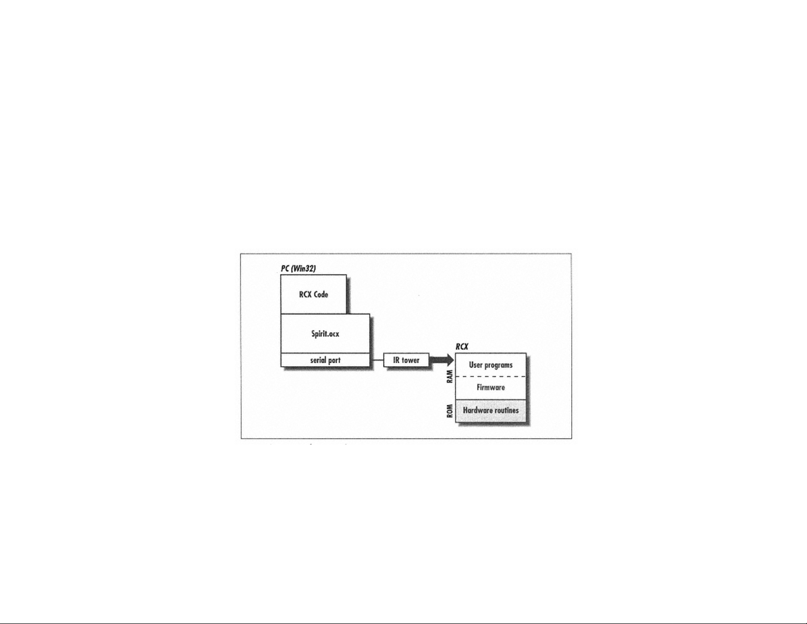
Now compile the source code using the nqc command:
C:\>nqc Hank.nqc
C:\>
If you made a mistake typing in the program, nqc gives you a list of errors. Otherwise, you're ready to download the program with the -d option:
c:\>nqc -d Hank.nqc
Downloading Program:…..complete
c:\>
(If you need to specify a serial port different from the default, use the -S option.)
Go ahead and run the program. When you're done playing, come back and get some background on the software that runs the RCX.
RCX Software Architecture
Writing a program for the RCX involves a handful of software layers, both on the development PC and on the RCX itself. Figure 4-1 shows an overview of the important pieces.
Page 55
Figure 4-1.
RCX software architecture
ROM
The RCX is a small computer that is based on a Hitachi H8/3292 microcontroller. The RCX contains two kinds of memory: Read Only Memory (ROM) and Random
Page 55

Page 56
Access Memory (RAM). As its name implies, ROM cannot be written. It is programmed at the factory and cannot be changed. RAM, on the other hand, can be written and read as many times as
you want, with one catch: it needs power. If you take the batteries out of your RCX, the contents of the RAM are erased. Under normal circumstances, however, the batteries preserve the contents
of the RAM.
When you first get your RCX, it has some stuff in ROM and an empty RAM. The RCX's ROM routines know a little bit about the RCX's hardware. These routines can run the motors or access the
sensors. Most importantly, the ROM routines know how to receive code from the IR port and place it in RAM.
Firmware
One of the first things you have to do with your RCX is download the firmware. The firmware is, essentially, an operating system for your RCX. The routines in ROM know how to download a
set of firmware from the IR port and store it in RAM. The firmware is capable of more than just processing the ROM routines. It shows a clock on the display of the RCX. It can recognize an
respond to the View button. Most importantly, it can receive robot programs over the IR port and run them.
Although at first it sounds like the firmware and the robot programs are the same kind of animal, this is not the case. The firmware is actual Hitachi H8 machine code. Together with the H8
machine code in ROM, the firmware defines an operating system for the RCX. It provides access to the RCX's inputs and outputs. It also provides a way for programs to be downloaded, stored,
started, and stopped.
The actual robot programs are not H8 machine code. They are defined at a higher level called bytecode. Whereas the H8 machine instructions are very rudimentary, such as "move this value to
register 1," bytecode instructions are more powerful, such as "turn output 2 on with full power." The firmware interprets the bytecode and performs the appropriate action.
About Spirit.ocx
On the PC side, a piece of software called Spirit.ocx handles interaction with the RCX via the IR link. Spirit.ocx can execute bytecode commands on the RCX, download new programs to the
RCX, download firmware to the RCX, and receive data from the RCX.
The RCX Code programming environment sits on top of Spirit.ocx. It provides the click-and-drag programming environment that you're already familiar with. RCX Code converts these graphic
programs into bytecode and uses Spirit.ocx to download the programs to the RCX.
Spirit.ocx is a regular ActiveX control, which means its functions are accessible from programming languages like Visual Basic and Visual C++.
Spruce Up That Resume
Writing programs for the RCX is an example of cross-compiling for an embedded system, a
phrase that is bound to sound good on your resume. Cross-compiling means that you are
writing programs on one computer (your PC) that will run on another computer (the RCX).
An embedded system is a computer that is part of some other device. For example,
microwave ovens and mobile phones both contain embedded systems. Modern cars contain
dozens of embedded systems, as well.
The usual way to develop software for a chip like the Hitachi H8 would be to use a cross
compiler running on a PC. You would write source code (probably in C or assembly
language) on your PC and use the cross-compiler to create H8 machine code from the
source. Then you would probably use a special PC peripheral, called a burner, to place the
machine code on some sort of programmable memory chip.
The final step would be to physically place the memory chip in the embedded system.
When the embedded system boots up, the software you just wrote will run.
Page 57
Page 56

The RIS software simplifies this process in two important ways. First, it provides a graphic
programming environment that's very accessible, particularly for people who haven't
programmed before. Second, programs are downloaded to the RCX over the IR link and
stored in RAM. This feature eliminates the complexity of dealing with memory chips and
burners yourself.
The cross-compilation step is a little different, too, because RCX programs are bytecode
rather than machine code. But it's still cross-compilation: the end result is bytecode rather
than H8 machine code.
A Day in the Life of a Program
Let's examine the typical life of a robot program:
1. The program's life begins when you create something in RCX Code. RCX Code compiles your program to bytecode.
2. RCX Code uses Spirit.ocx to download the program to one of the RCX's five program slots. The compiled bytecode is transferred to the RCX via the IR link.
3. The program is now available in RAM. When you run it, the firmware interprets the bytecode in your program and performs the appropriate tasks.
Page 58
NQC Overview
Where does NQC fit in? NQC is a replacement for the software on the PC, both RCX Code and Spirit.ocx. NQC source code is stored in simple text files, just like C, C++, or Java source code.
NQC compiles these source files to bytecode and can download them to the RCX using the IR tower. NQC is a good way to overcome the limitations of RCX Code. But because it produces
bytecode programs, it's still subject to the limitations of the firmware's bytecode interpreter.
Because NQC talks to the IR tower directly, without depending on Spirit.ocx, it is very portable. NQC runs on MacOS (using MPW), Linux, and of course Windows 95, 98, and NT. RCX Code,
by contrast, only runs on Windows.∗
NQC was developed by Dave Baum, who maintains the official web site at
http://www.enteract.com/~dbaum/lego/nqc/. His web site also includes pithy documentation for the language.
If you're using NQC on Windows, you might want to also use RCX Command Center (RcxCC). RcxCC is a Windows application that wraps around NQC. It provides a syntax-colored program
editor, push-button compilation and downloading, real-time control of the RCX, and a host of other useful features. Although NQC is fairly easy to use all by itself, RcxCC gives you an even
smoother ride. See the "Online Resources" at the end of this chapter for a URL and more information.
This chapter covers the important commands of NQC. If you have a background in C programming, the syntax and control structures will look familiar. If you don't have a background in C, don't
worry: NQC is easy to learn. I've included lots of example programs to demonstrate how things work. I won't cover NQC exhaustively; several excellent web pages detail the entire language. See
the "Online Resources" section at the end of this chapter for details.
main
NQC programs are organized into one or more tasks. A task is simply some set of instructions that execute in order. A task is analogous to a thread in other programming environments. A single
program may consist of several tasks that execute at the same time.
Tasks have names. Every program should have a special tasks called main. When the Run button is pressed, the RCX begins the program by running main. If you define other tasks, you have to
explicitly start and stop them. The main task is the only one that is automatically run by the RCX. I'll explain more about starting and stopping tasks later.
∗ As this book goes to press, a standalone MacOS version of NQC is being released in beta test form. Now you can run NQC on MacOs without MPW.
Page 57

Output Commands
NQC includes several commands for controlling the outputs of the RCX. You've already seen one of these, OnFwd, in our first simple example.
On(const outputs)
This command turns on the specified outputs. The outputs should be some combination of the constant values OUT_A, OUT_B, and OUT_C. Multiple outputs can be specified by adding them
together, as shown in the first example. When an output is turned on, its current power and direction are consulted to determine what actually happens.
Off(const outputs)
This command turns off the specified outputs, putting them in brake mode. For motors, this means that the motor shaft will be hard to turn.
Float(const outputs)
Float() is really a variation of Off(). No power is sent to the output, but the shaft of an attached motor will turn freely. This is a useful option if you want your robot to coast to a stop.
You can set the direction of outputs with the following three commands:
Fwd(const outputs)
Use this command to set the direction of the specified outputs to forward.
Rev(const outputs)
This command sets the direction of the specified outputs to reverse.
Toggle(const outputs)
To switch the direction of one or more outputs, use this command.
To determine the output power, use the following command:
Page 59
SetPower(const outputs, expression speed)
This command sets the power of the given outputs. Any expression that evaluates to a value from one to seven can be used as the speed. You may use the constant values OUT_LOW (1),
OUT_HALF (4), and OUT_FULL (7) if you desire.
To fully determine an output's actions, you should set its mode, direction, and power explicitly. By default, all three outputs are set to full power and the forward direction. Therefore, calling On()
is enough to get the motors running.
NQC provides two handy "combination" commands:
OnFwd(const outputs)
This command turns on the specified outputs in the forward direction.
OnRev(const outputs)
This command turns on the specified outputs in the reverse direction.
Page 58

Page 60
These commands set the mode and direction of the outputs in one fell swoop, but you should still set the power level explicitly with a call to SetPower().
For timed actions, the following command will come in handy:
OnFor(const outputs, expression time)
This command turns on the specified outputs for the given time, measured in hundredths of a second. Then the given outputs are turned off (in brake mode, not in float mode).
The following example runs outputs A and C forward, waits one second, then reverses outputs A and C. After another second, the outputs are turned off.
task main() {
SetPower(OUT_A + OUT_C, OUT_HALF);
Fwd(OUT_A + OUT_C);
OnFor(OUT_A + OUT_C, 100);
Rev(OUT_A + OUT_C);
OnFor(OUT_A + OUT_C, 100);
}
The On(), Off(), Float(), Fwd(), Rev(), and Toggle() commands are really shorthand for these lower-level output commands:
SetOutput(const outputs, const mode)
This command sets the mode for the given outputs. The outputs are specified in the same way as in the Fwd() and Rev() commands. The value of mode should be one of the constants
OUT_ON, OUT_OFF, and OUT_FLOAT.
SetDirection(const outputs, const direction)
This command determines the direction of the supplied outputs. The direction parameter should be OUT_FWD, OUT_REV, or OUT_TOGGLE. OUT_TOGGLE is a special value that sets the
direction of the output to the opposite of its current value.
In general, I recommend you don't call SetDirection() with the OUT_TOGGLE value. If you explicitly set the directions of your outputs, your program will be clearer. Furthermore, in
programs with more than one task, your program is more likely to behave as you expect.
Input Commands
Before you can read a value from one of the RCX's inputs, you need to tell the RCX what type of sensor is attached to the input. NQC provides a command that does just this:
Page 61
SetSensor(expression sensor, const configuration)
This command tells the RCX how to configure the given input. Valid values for sensor are SENSOR_1, SENSOR_2, and SENSOR_3, which represent the three inputs of the RCX. The sensor
configurations are detailed in Table 4-1. See Appendix A, Finding Parts and Programming Environments, which lists the sensors that are available for the RCX.
Page 59

Table 4-1. NQC Sensor Modes
Configuration Sensor Type Input Value ClearSensor()
SENSOR_TOUCH
SENSOR_LIGHT
SENSOR_ROTATION
SENSOR_CELSIUS
SENSOR_FAHRENHEIT
SENSOR_PULSE
SENSOR_EDGE
Touch 1 (pressed) or 0 (not pressed) -
Light 0 (dark) to 100 (bright) -
Rotation 16 units per full rotation yes
Temperature Celsius degrees times 10 -
Temperature Fahrenheit degrees times 10 -
Touch Count of presses yes
Touch Count of state transitions yes
The actual sensor value can be read using SENSOR_1, SENSOR_2, and SENSOR_3. These are shorthand for the following command:
SensorValue(const input)
This command returns the current value of the given input, which should be 0, 1, or 2, for input 1, input 2, and input 3 respectively. The values returned from an input depend on the input's
configuration and are described in Table 4-1.
SENSOR_1, SENSOR_2, and SENSOR_3 actually have a dual purpose in life. Their first purpose is to identify the inputs on the RCX to commands like
SetSensor(). Their second purpose is to retrieve values from the inputs. Thus, there are two distinct uses for SENSOR_1, SENSOR_2, and SENSOR_3.
The SENSOR_PULSE and SENSOR_EDGE configurations are variations on SENSOR_TOUCH. The SENSOR_PULSE configuration counts the times the touch sensor has been pressed, while
SENSOR_EDGE counts the transitions from on to off and from off to on. When you read the value of an input in one of these configurations, the input value is the accumulated count.
The configurations that keep a count can be reset with a call to ClearSensor() (as shown in Table 4-1):
ClearSensor(expression sensor)
This command resets the current count for the given input to 0.
Edges and Pulses
If you examine the output of a touch sensor, over time, it looks something like this:
Page 62
Page 60

The transitions from 0 to 1 and from 1 to 0 are called edges. A transition from 0 to 1 is a
rising edge, while a transition from 1 to 0 is a falling edge.
The SENSOR_EDGE configuration counts all edges, rising or falling. SENSOR_PULSE is a
little more selective—it counts rising edges only.
The following example plays a sound after every fourth press on the touch sensor. It begins by configuring input 1 to count touch presses with the SENSOR_PULSE configuration. Then it enters
an endless loop, repeatedly testing the value of input 1. If it is 4, a sound is played, and the count for input 1 is reset.
task main() {
SetSensor(SENSOR_1, SENSOR_PULSE);
while(true) {
if (SENSOR_1 == 4) {
PlaySound(SOUND_DOWN);
ClearSensor(SENSOR_1);
}
}
}
The SetSensor() command actually configures an input's type and mode at the same time. The input type describes the electrical characteristics of the attached sensor, while the mode
determines how the sensor values are interpreted. If you need finer control over the inputs than you can get from SetSensor(), use the SetSensorType() and SetSensorMode()
commands:
Page 63
SetSensorType(expression sensor, const type)
This command specifies the type of sensor attached to the given input. Input types are listed in Table 4-2. This command specifies how the RCX should treat an input, electrically speaking. The
SENSOR_TYPE_LIGHT type, for example, supplies power to the sensor. (I described this back in Chapter 3.)
Page 61

Table 4-2. Input Type Constants
Type Constant Sensor Type
SENSOR_TYPE_TOUCH
SENSOR_TYPE_TEMPERATURE
SENSOR_TYPE_LIGHT
SENSOR_TYPE_ROTATION
Touch sensor
Temperature sensor
Light sensor (powered)
Rotation sensor (powered)
SetSensorMode(expression sensor, const mode)
Use this command to set the mode of the given input. While the SetSensorType() command is used to specify the electrical characteristics of the input, the SetSensorMode() command
specifies how the input value should be processed. The modes are listed in Table 4-3.
Table 4-3. Input Mode Constants
Mode Constant Description
SENSOR_MODE_RAW
SENSOR_MODE_BOOL
SENSOR_MODE_EDGE
SENSOR_MODE_PULSE
SENSOR_MODE_PERCENT
SENSOR_MODE_CELSIUS
Raw sensor value from 0 to 1023
Either 1 or 0
Counts transitions from 1 to 0 and vice versa
Counts transitions from 1 to 0
Percent from 0 to 100
Celsius temperature
SENSOR_MODE_FAHRENHEIT
SENSOR_MODE_ROTATION
Fahrenheit temperature
Shaft angle, 16 counts per full revolution
Internally, input values initially have a raw value from 0 to 1023. Raw values are converted to the input values that your program sees by a process that depends on the input mode. Three of the
modes count events: SENSOR_MODE_EDGE, SENSOR_MODE_PULSE, and SENSOR_MODE_ROTATION. The other modes perform a mathematical scaling operation on the raw input value.
For example, if the input mode is SENSOR_MODE_PERCENT, the RCX converts the raw value into a percent according to the equation:
Page 62

Page 64
If you wanted to attach a temperature sensor to input 2 and measure Celsius values, you would do the following:
SetSensorType(SENSOR_2, SENSOR_TYPE_TEMPERATURE);
SetSensorMode(SENSOR_2, SENSOR_MODE_CELSIUS);
The SetSensor() command, which I described first in this section, is a convenient way of specifying both an input type and an input mode. Table 4-4 shows what types and modes correspond
to the configurations that SetSensor() recognizes.
Table 4-4. Input Configurations, Types, and Modes
Input Configuration Input Type Input Mode
SENSOR_TOUCH SENSOR_TYPE_TOUCH SENSOR_MODE_BOOL
SENSOR_PULSE SENSOR_TYPE_TOUCH SENSOR_MODE_PULSE
SENSOR_EDGE SENSOR_TYPE_TOUCH SENSOR_MODE_EDGE
SENSOR_LIGHT SENSOR_TYPE_LIGHT SENSOR_MODE_PERCENT
SENSOR_CELSIUS SENSOR_TYPE_TEMPERATURE SENSOR_MODE_CELSIUS
SENSOR_FAHRENHEIT SENSOR_TYPE_TEMPERATURE SENSOR_MODE_FAHRENHEIT
SENSOR_ROTATION SENSOR_TYPE_ROTATION SENSOR_MODE_ROTATION
Timers
The RCX has four internal timers, numbered 0, 1, 2, and 3. They count in increments of 100 ms, or once every 1/10 seconds. NQC includes two commands for interacting with the timers:
Timer(const n)
This returns the value of the specified timer, which should be 0, 1, 2, or 3. The number returned is the number of 1/10 seconds since the timer was cleared.
ClearTimer(const n)
This command resets the value of the given timer to 0. The timer begins counting up again immediately.
Random Numbers
NQC has a simple command for creating random numbers. Random numbers are often useful in robot programming. For example, a robot that tries to drive around obstacles can easily get stuck in
a corner if it always backs up and turns exactly the same way to get away from an obstacle. A robot that backs up for a random amount of time and turns for a random amount of time is less likely
to get stuck in this way. The command for generating random numbers is:
Random(const n)
This command returns a random number between 0 and n.
Page 63

Page 65
Program Flow
You've seen how to control the RCX's outputs and inputs. But robot programs aren't very interesting unless they can make decisions and repeat actions. In this section, I'll sketch out NQC's
program control commands. NQC supports a standard set of conditional branches and loops; if you've ever programmed in other languages (particularly C), this will look familiar.
Waiting
Although it might not seem important, NQC includes a command that tells the robot to do nothing for a certain amount of time. This is often useful if you need to allow some time for something to
happen—maybe the robot needs to move forward or turn for a little while, or you want to give a sound time to play. The command is:
Wait(expression ticks)
This command causes the current task to pause for the supplied hundredths of a second; a call to Wait(100) will pause the task for a full second. Note that this only applies to the current
task—other tasks will continue to execute. I'll talk more about tasks a little later.
A variation on this theme is the concept of waiting for an event, like a press on a touch sensor, or a certain time of day. The following command waits for a condition to become true:
until (boolean condition) [statements]
Use this command to wait for the given condition to become true. You could, for example, wait for the value of input 1 to become 4 like this:∗
until (SENSOR_1 == 4);
This particular until has an empty body, which means it won't do anything each time the condition is tested—it simply waits until the condition is true. The following program beeps every
half second until you press a touch sensor on input 1 four times:
task main() {
SetSensor(SENSOR_1, SENSOR_PULSE);
until (SENSOR_1 == 4) {
PlaySound(SOUND_CLICK);
Wait(50);
}
}
∗ As in C, conditional expressions are very different from evaluations. Use
== to compare values and = to assign values.
Loops
A loop is a series of commands that you want to be executed repeatedly. NQC offers three flavors of loop:
repeat (expression value) [statements]
This command simply repeats the given statements value times.
while (boolean condition) [statements]
This loop repeats the supplied statements until condition is no longer true.
do [statements] while (boolean condition)
This loop is similar to while but the statements are executed before the condition is tested. The statements will always be executed at least once, which is not true for a while loop.
Let's look at an example. The following code plays a sound every half second while a light sensor attached to input 3 sees dark:
Page 66
Page 64

while (SENSOR_3 < 35) {
PlaySound(0);
Wait(50);
}
Notice how curly braces are used to bracket the statements that belong to the while loop. If you have only one command in the body of the while, you can omit the braces like this:
while (SENSOR_3 < 35)
Wait(50);
Conditionals
To test a condition, use the if command.
if (boolean condition) [statements]
This command executes the given statements only if condition is true.
if (boolean condition) [statements] else [statements]
This is a simple variation on the basic if command. If the condition is false, the statements after the else are executed.
The following example turns different directions depending on the value of input 2:
SetPower(OUT_A + OUT_C, OUT_FULL);
if (SENSOR_2 < 50) {
Fwd(OUT_A);
Rev(OUT_C);
}
else {
Rev(OUT_A);
Fwd(OUT_C);
}
On(OUT_A + OUT_C);
Page 67
Variables
To use a variable, you simply need to declare its name. Only integer variables are supported. Once a variable is declared, you can assign the variable values and test it in the body of the program.
Here's a simple example:
int i;
task main() {
i = 0;
while (i < 10) {
PlaySound (0);
Wait(5 ∗ i);
i += 1;
}
}
This example beeps at successively longer intervals. The variable, i, is declared in the very first line:
int i;
Values are assigned to the variable using the = operator:
Page 65

i = 0;
You can also assign input values to variables, like this (not part of the example):
i = SENSOR_2;
In the following line, one is added to the value in variable i:
i++;
This is really shorthand for the following:
i += 1;
The += operator, in turn, is shorthand for this:
i = i + 1;
Using #define for Constants and Macros
Constant values can be assigned meaningful names using #define. This is a idiom that will be familiar to C programmers. Here is an example:
#define POWER 5
task main() {
SetPower(OUT_A + OUT_C, POWER);
On(OUT_A + OUT_C);
}
NQC replaces every occurrence of POWER with 5 in your source code before compiling it. Although this may not seem like a big deal, it is; #define lets you create
Page 68
readable names for things that might otherwise be cryptic. It also lets you define things that might need to be adjusted throughout your program in one place. Your program, for example, might
have multiple places where it set the outputs to power level 5. Instead of explicitly putting 5 all the way through your program, you can use the constant value POWER. If you later decide you want
the power level to be 7, you just have to change the definition of POWER, instead of finding all the places in your program where the output power is set.
You can also create macros with #define. A macro is a kind of miniature program. Usually you'll define a macro for something you want to do frequently. The following program uses three
macros:
#define forward(power) \
SetPower(OUT_A + OUT_C, power); \
OnFwd(OUT_A + OUT_C);
#define left(power) \
SetPower(OUT_A + OUT_C, power); \
OnRev(OUT_A); OnFwd(OUT_C);
#define right(power) \
SetPower(OUT_A + OUT_C, power); \
OnFwd(OUT_A); OnRev(OUT_C);
task main() {
forward(OUT_FULL);
Wait(100);
left(OUT_HALF);
Wait(100);
right(OUT_HALF);
Wait(100);
Off(OUT_A + OUT_C);
Page 66

}
The preceding example shows off two features of macros. First, each macro has a parameter, power, that is used in the body of the macro. Second, the macros are split out to multiple lines by
using a backslash.
Sounds and Music
Your RCX can play various prepackaged sounds, using the following command:
PlaySound(const n)
This command plays the sound represented by n. NQC includes constant names for each available sounds, as detailed in Table 4-5.
Table 4-5. RCX System Sounds
Sound Name Description
SOUND_CLICK
SOUND_DOUBLE_BEEP
Short beep
Two medium beeps
(table continued on next page)
Page 69
(table continued from previous page)
Table 4-5. RCX System Sounds (continued)
Sound Name Description
SOUND_DOWN
SOUND_UP
SOUND_LOW_BEEP
SOUND_FAST_UP
Descending arpeggio
Ascending arpeggio
Long low note
Quick ascending arpeggio (same as SOUND_UP but faster)
If you'd prefer to make your own music, you can play individual notes with the PlayTone() command:
PlayTone(const frequency, const duration)
This command plays a note with the given frequency for the specified duration. The frequency is in Hz, so 440 is the pitch of the A above middle C on a piano. The duration is in hundreths of a
second. You can only specify integer values for the frequency, so don't expect the pitches to be exactly in tune. No one expects your little robot to sound like Pavorotti.
If you want to play a sequence of notes, you have to be a little tricky about it. Each time you call PlayTone(), the command returns almost immediately, with-out waiting for the sound you've
requested to finish playing. The tone you've requested is put in a queue; the system plays it while the rest of your program executes. If you call PlayTone() repeatedly, the queue will fill up.
Subsequent calls to PlayTone() will not fit on the queue and the tones you've requested will not be played. The queue is long enough to hold eight tones. If you want to play a sequence longer
than this, you should insert calls to Wait() in your program so that the queue has time to empty out as notes are played.
The following example demonstrates this technique; it plays part of Quando men vo, from Giacomo Puccini's La Bohème.
Page 67

#define SIXTH 12
#define HALF 3∗SIXTH
#define BEAT 2∗HALF
#define GRACE 6
task main() {
PlayTone(330, 2∗BEAT);
Wait(2∗BEAT + 2∗SIXTH);
PlayTone(115, SIXTH);
PlayTone(208, SIXTH);
PlayTone(247, SIXTH);
PlayTone(330, SIXTH);
PlayTone(311, 2∗BEAT);
Wait(4∗SIXTH + 2∗BEAT + 2∗SIXTH);
PlayTone(115, SIXTH);
PlayTone(208, SIXTH);
PlayTone(247, SIXTH);
PlayTone(311, SIXTH);
PlayTone(277, 3∗BEAT);
Wait(4∗SIXTH + 3∗BEAT + HALF);
PlayTone(277, HALF);
PlayTone(311, HALF);
PlayTone(370, GRACE);
PlayTone(330, HALF);
PlayTone(311, HALF); Wait (2∗HALF);
PlayTone(277, HALF);
PlayTone(330, HALF);
PlayTone(220, HALF);
PlayTone(220, 2∗BEAT);
Wait(GRACE + 5∗HALF + 2∗BEAT + HALF);
PlayTone(247, HALF);
PlayTone(277, HALF);
PlayTone(330, GRACE);
PlayTone(311, HALF);
PlayTone(277, HALF); Wait (2∗HALF);
PlayTone(247, HALF);
PlayTone(311, HALF);
PlayTone(208, HALF);
PlayTone(208, 2∗BEAT);
Wait(GRACE + 5∗HALF + 2∗BEAT + HALF);
}
Page 70
IR Communication
Your robot can send and receive data over its IR port. In NQC, three commands handle sending and receiving data:
SendMessage(expression m)
This command sends the given byte of data out the IR port.
Page 68

Message()
Use this command to return the last byte of data received on the IR port.
ClearMessage()
This command clears the incoming message. You may want to do this after responding to an incoming message, to avoid responding more than once.
The Display
Although you can't control the display directly in NQC, you can configure it to some degree:
SelectDisplay(expression v)
This command tells the RCX to show the data source represented by v on its display. The legal values for v are shown in Table 4-6. You can achieve the same results by pressing the View button
on the front of the RCX to show the state of the inputs or outputs, but the SelectDisplay() command allow you to do this as part of a program.
Page 71
Table 4-6. Display Values
Value Description
0 System clock
1 View Input 1
2 View Input 2
3 View Input 3
4 View Output A
5 View Output B
6 View Output C
You can set the clock in the RCX using the following macro:
SetWatch(const hours, const minutes)
Use this macro to set the current time of the RCX's clock. Unfortunately, only constant values can be used.
The Datalog
With the default firmware, your RCX supports an interesting option called a datalog. The datalog is simply a list of numbers. You can create a new datalog and put numbers into it. Datalogs can
be uploaded to your PC for analysis or display. The datalog commands are:
CreateDatalog(const size)
This command tells the RCX to make space for the given number of elements. There is only one datalog, so this command will erase any previous datalog.
AddToDatalog(expression v)
This command adds a value to the datalog. It's up to you to keep track of how many values are in the datalog. If you try to add values after the datalog is full, nothing happens.
The following example waits for a touch sensor on input 1 to be pressed. For each press, the value of timer 0 is stored in the datalog, which holds 20 values in this example:
Page 69

int count;
task main() {
CreateDatalog(20);
ClearTimer(0);
SetSensor(SENSOR_1, SENSOR_TOUCH);
count = 0;
until (count == 20) {
until(SENSOR_1 == 1);
AddToDatalog(Timer(0));
count++;
until(SENSOR_1 == 0);
}
}
When you run this program, you'll notice the RCX shows the status of the datalog on the right side of the display. It looks kind of like a pie; as you add values to the datalog the pie fills up.
To upload a datalog to the PC, you can use nqc's -datalog option, which simply dumps the values to the screen:
C:\>nqc -datalog
8
12
16
19
23
25
27
29
31
33
39
47
52
56
59
62
65
68
71
75
Page 72
C:\>
The datalog actually stores the source of every value. If you use a tool like RCX Command Center, it can show you the source of each value in the datalog. In Chapter 8, Using Spirit.ocx with
Visual Basic, I'll show you how to write your own program in Visual Basic to retrieve the contents of the datalog.
Tasks
NQC gives you powerful control over tasks and subroutines. Each of the RCX's five programs is made up of one or more tasks. These tasks can execute at the same time, which is another way of
saying that the RCX is multitasking.
Tasks are defined using the task command. Every program must have a main task which is executed when the program is first started. Other tasks must be started and stopped explicitly:
Page 70

start taskname
This command starts the named task.
stop taskname
Use this command to stop the named task.
The following program controls its outputs from main and uses another task, sing, to play some music. The sing task has to be started from main; otherwise, its commands will never be
executed.
task main() {
start sing;
while (true) {
OnFwd(OUT_A);
OnRev(OUT_C);
Wait(100);
OnFwd(OUT_C);
OnRev(OUT_A);
Wait(100);
}
}
#define SIXTH 12
#define HALF 3∗SIXTH
#define BEAT 2∗HALF
#define GRACE 6
Page 73
task sing() {
PlayTone(330, 2∗BEAT);
Wait(2∗BEAT + 2∗SIXTH);
PlayTone(115, SIXTH);
PlayTone(208, SIXTH);
PlayTone(247, SIXTH);
PlayTone(330, SIXTH);
PlayTone(311, 2∗BEAT);
Wait(4∗SIXTH + 2∗BEAT + 2∗SIXTH);
PlayTone(115, SIXTH);
PlayTone(208, SIXTH);
PlayTone(247, SIXTH);
PlayTone(311, SIXTH);
PlayTone(277, 3∗BEAT);
Wait(4∗SIXTH + 3∗BEAT + HALF);
PlayTone(277, HALF);
PlayTone(311, HALF);
PlayTone(370, GRACE);
PlayTone(330, HALF);
PlayTone(311, HALF); Wait (2∗HALF);
PlayTone(277, HALF);
PlayTone(330, HALF);
PlayTone(220, HALF);
PlayTone(220, 2∗BEAT);
Wait(GRACE + 5∗HALF + 2∗BEAT + HALF);
PlayTone(247, HALF);
Page 71

Page 74
PlayTone(277, HALF);
PlayTone(330, GRACE);
PlayTone(311, HALF);
PlayTone(277, HALF); Wait (2∗HALF);
PlayTone(247, HALF);
PlayTone(311, HALF);
PlayTone(208, HALF);
PlayTone(208, 2∗BEAT);
Wait(GRACE + 5∗HALF + 2∗BEAT + HALF);
stop main;
Float(OUT_A + OUT_C);
}
When the sing task is done playing music, it stops the main task with the stop command. Then it turns the motors off. The order is critical. If we turned off the motors and then stopped the
main task, it's possible that main would turn on the motors again before it was stopped. Multithreaded programming is powerful but tricky.
Each RCX program can have up to ten tasks.
Subroutines
A subroutine is a group of commands that you will execute frequently. Subroutines offer a way to clean up your source code and reduce the size of compiled programs. Subroutines in NQC are
defined in much the same way as tasks. The following program has one subroutine, called wiggle(). The main task shows how this subroutine is called:
task main() {
wiggle();
Wait(200);
wiggle();
}
sub wiggle() {
OnFwd(OUT_A);
OnRev(OUT_C);
Wait(20);
OnFwd(OUT_C);
OnRev(OUT_A);
Wait(20);
Off(OUT_A + OUT_C);
}
Subroutines execute as part of the task from which they are called. It works just as if the call to wiggle() was replaced with the commands it contains. The nice thing about subroutines is that
their code is defined once, but you can call it as many times as you like from other places in your program. You could accomplish the same sorts of things with subroutines and macros, but
subroutines are more
Page 72

Page 75
efficient because the code is just compiled once. With a macro, the entire macro body would be placed at each point where it was called.
The RCX imposes three crippling restrictions on subroutines. First, you can't call another subroutine from within a subroutine. As a consequence, a subroutine also cannot call itself. Second, you
can't pass parameters to a subroutine or get a return value. Third, no more than eight subroutines can be defined for a single program. These limitations are imposed by the RCX's bytecode
interpreter, which is defined in the firmware. To get around restrictions like these, you'll need to use a different firmware, like legOS or pbForth.
Inlines
NQC does offer another interesting option, the inline subroutine. In source code, it looks a lot like a subroutine except with a C-style return type (always void):
void wiggle() {
OnFwd(OUT_A);
OnRev(OUT_C);
Wait(20);
OnFwd(OUT_C);
OnRev(OUT_A);
Wait(20);
Off(OUT_A + OUT_C);
}
Inlines are called the same way as subroutines. The compiler actually places the code of the inline wherever it is called, almost like a macro or constant definition. This actually makes inlines
appear a little more capable than subroutines: they can call other inlines or even subroutines. In NQC version 2.0, for example, you can define inlines with a parameter, like this:
void wiggleTime(int waitTime) {
OnFwd(OUT_A);
OnRev(OUT_C);
Wait(waitTime);
OnFwd(OUT_C);
OnRev(OUT_A);
Wait(waitTime);
Off(OUT_A + OUT_C);
}
You can have more than one argument, if you wish. Just remember that inlines are really an example of syntactic sugar, something that makes your source code look pretty but doesn't necessarily
result in better efficiency.
Arguments to inlines can be passed in four different ways. Table 4-7 summarizes the options.
Page 76
Table 4-7. Argument Passing for Inlines
Type By Value or By Reference? Temporary Variable Used?
int
const int
int&
const int&
by value yes
by value no
by reference no
by reference no
Page 73

If you pass int by value, the parameter's value is copied into a temporary variable (from the pool of 31) and used in the inline. const int passes by value, but the value must be a constant at
compile time.
If you pass by reference, the variable that is passed in can actually be modified in the inline. In this code, for example, a count variable is incremented in the body of an inline:
task main() {
int count = 0;
while (count <= 5) {
PlaySound(SOUND_CLICK);
Wait(count ∗ 20);
increment(count);
}
}
void increment(int& n) {
n++;
}
The last option, const int &, is used when you want to pass a value that should not be changed. This is great for things like Sensor() and Timer(). For example, you might have an inline
like this:
void forward(const int& power) {
SetPower(OUT_A + OUT_C, power);
OnFwd(OUT_A + OUT_C);
}
With this inline, you can do normal things, like passing a variable or constant:
int power = 6;
forward(power);
forward(OUT_HALF);
But you can also do trickier stuff, like this:
forward(Message());
You can basically accomplish the same stuff with int parameters and const int& parameters. The advantage of const int& is that no temporary variables are used.
Page 77
Trusty Revisited
You've seen some small examples of NQC code. Now I'll show you how Trusty can be programmed using NQC. You'll be able to compare the NQC programs to the RCX Code programs from
Chapter 3.
New Brains For Trusty
As you may recall, we used a counter to keep track of Trusty's state. The counter value was used to decide if Trusty would turn left or right the next time the light sensor left the black line. In
NQC, we can store Trusty's state in a real variable. Plus, we'll use symbolic constants to represent state values.
int state;
#define LEFT 0
#define RIGHT 1
Trusty's program has two tasks. The first task (main) tests the value of the light sensor. If it is over the black line, the robot is set to move forward:
Page 74

while (true) {
if (SENSOR_2 < DARK2)
OnFwd(OUT_A + OUT_C);
}
The DARK2 and POWER constants are determined using #defines; this means it's easy to fiddle with their values, and our program is easy to read.
The second task takes care of things when the light sensor leaves the black line. Whenever the robot leaves the line, the toggle() subroutine is called. toggle() starts the robot turning. Then
we wait a little while; if the robot is still not on the black line, we call toggle() again to turn back the other way:
task lightWatcher() {
while (true) {
if (SENSOR_2 > LIGHT2) {
toggle();
Wait(TIMEOUT);
if (SENSOR_2 > LIGHT2) {
toggle();
Wait(TIMEOUT ∗ 2);
}
}
}
}
The toggle() subroutine performs two important functions. First, it makes Trusty turn, based on the value of the state variable. Second, it updates the value of state; if it was RIGHT, it
will be LEFT, and vice versa.
Page 78
Here is the whole program:
int state;
#define LEFT 0
#define RIGHT 1
#define DARK2 35
#define LIGHT2 40
#define POWER 7
#define TIMEOUT 50
task main() {
state = LEFT;
SetSensor(SENSOR_2, SENSOR_LIGHT);
SetPower(OUT_A + OUT_C, POWER);
start lightWatcher;
while (true) {
if (SENSOR_2 < DARK2)
OnFwd(OUT_A + OUT_C);
}
}
task lightWatcher() {
while (true) {
Page 75

if (SENSOR_2 > LIGHT2) {
toggle();
Wait(TIMEOUT);
if (SENSOR_2 > LIGHT2) {
toggle();
Wait(TIMEOUT ∗ 2);
}
}
}
}
sub toggle() {
if (state == LEFT) {
OnRev(OUT_A);
OnFwd(OUT_C);
state = RIGHT;
}
else {
OnFwd(OUT_A);
OnRev(OUT_C);
state = LEFT;
}
}
The main task performs three important initializations which I haven't mentioned yet. First, main initializes the value of the state variable. It just uses LEFT
Page 79
arbitrarily. Next, main configures input 2 for a light sensor. Finally, it starts the lightWatcher task.
Using Two Light Sensors
In this section, I'll present an NQC program that works with the two light sensor version of Trusty. As you may recall, programming this robot in RCX Code was cumbersome.
The programming is a lot cleaner in NQC. It's pretty straightforward to translate Table 3-1 into source code. The basic strategy is to use a state variable to represent the four states of the robot,
represented by the four lines of Table 3-1. Then one task examines the sensors and updates the state variable. Another task examines the state variable and sets the motors appropriately.
The four possible states are represented by constant values. A fifth value, INDETERMINATE, is used when one or both of the light sensor values is not in the dark or light range:
#define BOTH_ON 3
#define LEFT_ON 1
#define RIGHT_ON 2
#define BOTH_OFF 0
#define INDETERMINATE 255
The main task simply tests the value of the state variable and sets the motors accordingly. No action is taken for BOTH_OFF and INDETERMINATE:
Page 76

while (true) {
if (state == BOTH_ON)
OnFwd(OUT_A + OUT_C);
else if (state == LEFT_ON) {
Off(OUT_A);
OnFwd(OUT_C);
}
else if (state == RIGHT_ON) {
Off(OUT_C);
OnFwd(OUT_A);
}
}
A separate task, watcher, examines the light sensor values and sets the state variable. Here is the entire source code for the two sensor version of Trusty:
int state;
// "ON" refers to whether the light
// sensor is on the line. If it is,
// the light sensor is seeing black.
#define BOTH_ON 3
#define LEFT_ON 1
#define RIGHT_ON 2
#define BOTH_OFF 0
#define INDETERMINATE 255
Page 80
// Thresholds for light and dark.
#define DARK2 35
#define LIGHT2 40
#define DARK3 40
#define LIGHT3 45
#define POWER 4
task main() {
initialize();
while (true) {
if (state == BOTH_ON)
OnFwd(OUT_A + OUT_C);
else if (state == LEFT_ON) {
Off(OUT_A);
OnFwd(OUT_C);
}
else if (state == RIGHT_ON) {
Off(OUT_C)
OnFwd(OUT_A);
}
}
}
sub initialize() {
SetSensor (SENSOR_2, SENSOR_LIGHT);
SetSensor (SENSOR_3, SENSOR_LIGHT);
Page 77

SetPower(OUT_A + OUT_C, POWER);
OnFwd(OUT_A + OUT_C);
start watcher;
}
task watcher() {
while (true) {
if (SENSOR_2 < DARK2) {
if (SENSOR_3 < DARK3) state = BOTH_ON;
else if (SENSOR_3 > LIGHT3) state = LEFT_ON;
else state = INDETERMINATE;
}
else if (SENSOR_2 > LIGHT2) {
if (SENSOR_3 < DARK3) state = RIGHT_ON;
else if (SENSOR_3 > LIGHT3) state = BOTH_OFF;
else state = INDETERMINATE;
}
else state = INDETERMINATE;
}
}
Page 81
Online Resources
NQC—Not Quite C
http://www.enteract.com/~dbaum/lego/nqc/
This is the official site for NQC. You can download the current release, read the documentation, or browse a FAQ. Dave Baum has packed a lot of useful information into this site, including such
gems as how to create a cable to connect your Macintosh to the IR tower. This site also includes the definitive NQC documentation.
Lego Robots: RCX Command Center
http://www.cs.uu.nl/people/markov/lego/rcxcc/
RCX Command Center (RcxCC), developed by Mark Overmars, is built on top of NQC. It's a Windows application that provides a friendly graphic interface to the features of NQC. It includes a
syntax-colored program editor, real-time control of the RCX, utilities for making your RCX play music, and useful help files. I highly recommend this application.
Lego Robot Pages [NQC Tutorial]
http://www.cs.uu.nl/people/markov/lego/
Mark Overmars, creator of RcxCC (the previous entry), has written a detailed introduction to NQC. It's available off his main web page as PDF, Word97, PostScript, or RTF. This document is a
gentle and thorough introduction to NQC.
Kevin Saddi's NQC Reference Page
http://home1.gte.net/ksaddi/mindstorms/nqc-reference.html
This page provides a distilled view of NQC. It's very handy when you can't remember the input type constants, or you'd like to see NQC's commands organized by function. Single-line code
samples are also included.
Hitachi Single-Chip Microcomputer H8/3297 Series…
http://semiconductor.hitachi.com/products/pdf/h33th014d2.pdf
This PDF document has all the crufty details on the Hitachi H8 that forms the heart of the RCX. The specific model is the H8/3292, which is covered in the manual. This information is not for
casual browsing—you probably won't need to look here unless you start writing your own firmware. (Hitachi's web site is a little flakey. If you're having trouble with this URL, try starting at the
URL
http://semiconductor.hitachi.com/h8/ and searching for the H8/3292.)
Page 78

5 Minerva, a Robot with an Arm
In this chapter:
• Building Instructions
• Programming
• Directional Transmission
• Pulleys
• Mechanical Design
• Two Sensors, One Input
Page 82
• Where Am I?
• Online Resources
Minerva is a mechanical marvel. Although she has the same wheel layout as Trusty, Minerva's drivetrain is radically different. In addition, she has a simple arm with a grabber, which allows her to
pick up and drop small objects. Best of all, Minerva can be built with the pieces from the RIS alone. The grabber arm is operated by a single motor. The other motor powers the drivetrain, which
moves the robot forward or spins it in place. Figure 5-1 shows a picture of this remarkable robot.
Page 79

Figure 5-1.
Minerva, a mechanical masterpiece
When you run Minerva's program, she drives straight forward. When the light sensor (mounted on the end of the grabber arm) sees something dark, Minerva stops driving. She uses the arm to try
to pick up whatever the light sensor saw. Then
Page 83
she turns around and drives back to her starting point. She puts down whatever she's carrying, turns around and is ready to start again.
Building Instructions
If there's one lesson to be learned from Minerva, it is that mechanical design is hard. I had to build this robot five times to get it right. And I don't mean I moved a few pieces around—I actually
disassembled and rebuilt the robot that many times. The drivetrain alone took four tries before I got it right.∗
Directional Transmission and Drivetrain
The long gray piece in Step 1 swivels freely on the shaft.
∗ Minerva uses almost all of the gears that come with RIS 1.0. Unfortunately, RIS 1.5 comes with fewer gears (five 12t gears instead of eight). To get the extra gears you'll need for Minerva, you can
order the #5229 Gears & Differentials parts pack from the LEGO Shop At Home Service, (800) 453–4652. Cost is $4.50 including shipping.
The 8u shaft in Step 2 is loose and may fall out. It will be anchored in the next step. The 6u beam, like the long gray piece from Step 1, swivels freely on its shaft.
Page 84
Page 80

Make sure the bump on the long pin is up against the 4u beam.
Page 85
Page 81

Before you put all of Step 7 together, make sure the swiveling parts from Steps 1 and 2 are pointing up, as shown.
Page 86
Page 82

Page 83

Page 87
Step 11 is tricky. You'll need to slide the 8u shaft into the structure, adding bushings and gears as you go. The swiveling pieces from Steps 1 and 2 are now anchored.
Page 88
Page 89
Page 84
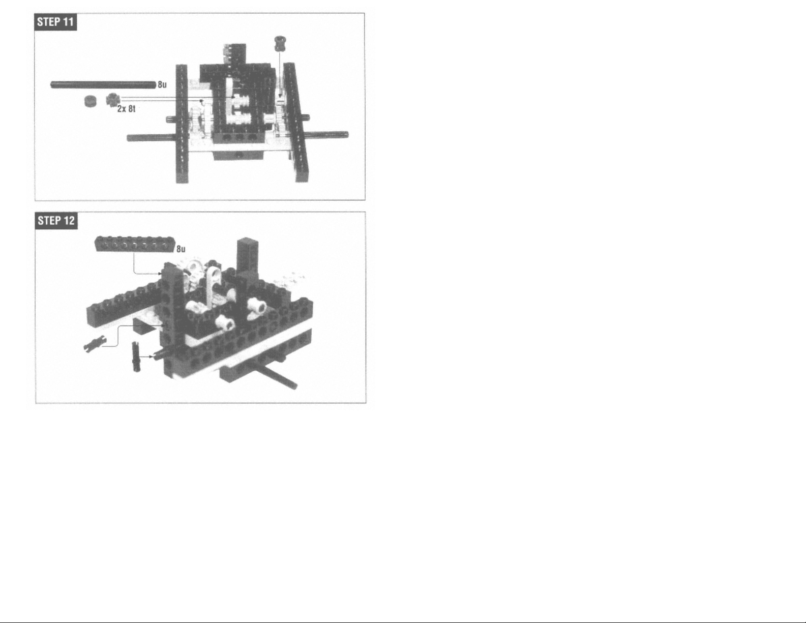
Page 85
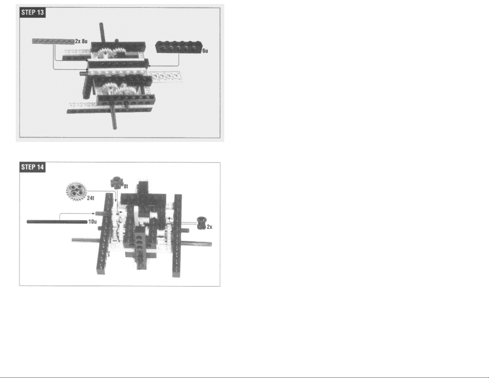
Step 14 is similar to Step 11; take a deep breath and go slowly.
Page 86
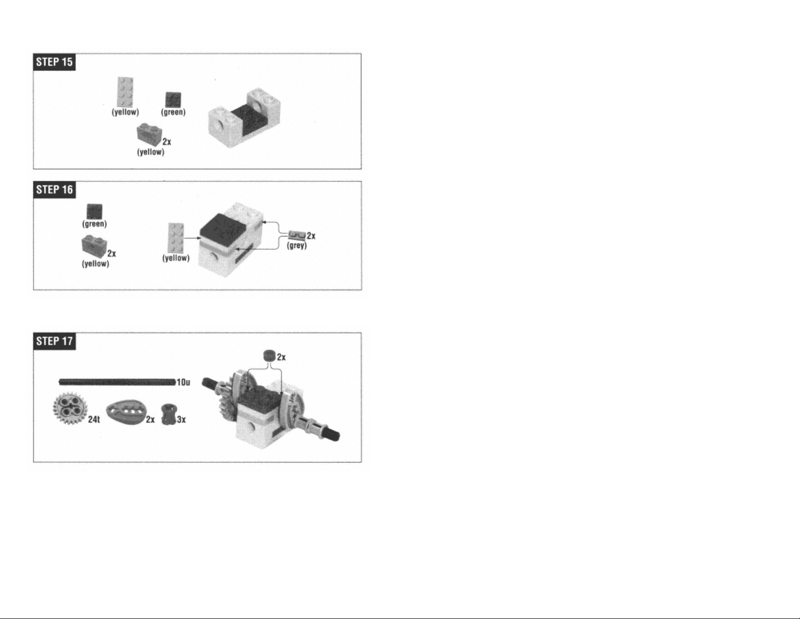
Grabber Arm
Page 90
In Step 17, the half-bushings go between the center block and the cams (pear-shaped pieces).
Page 87

Page 91
Page 88

Page 92
Make sure that the two sides are at the same angle. They should mirror each other.
Page 89

Page 93
Page 94
Page 90

Structural Support
Page 95
Page 91
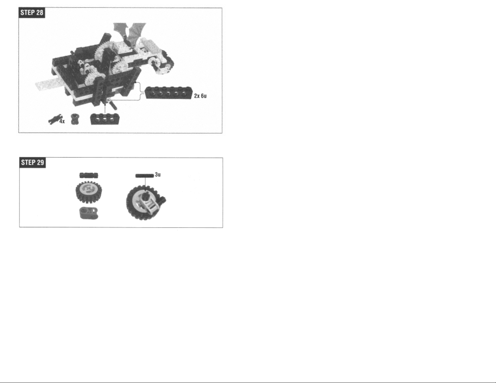
Idler Wheel
Page 96
Page 92

Drive Motor
Page 97
Page 93

While you're putting the motor in, hold on to the worm gear so it doesn't slip off.
Page 98
Page 94

Grabber Arm Motor
Page 95

Page 99
Page 96
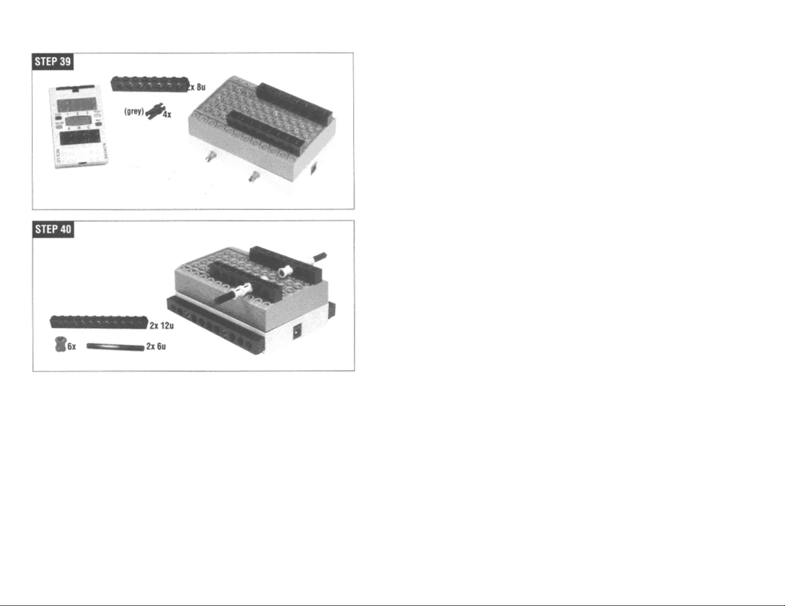
RCX
Page 100
Attach the RCX on both sides as shown.
Page 101
Page 97

Wiring
First, attach the left motor, which powers the arm, to output A. Then use a wire brick to attach the right motor (the drive motor) to output C.
Page 98

Attach the light sensor to the front of the arm. The wire attaches to Minerva's side as shown.
Next, use a wire brick to attach the touch sensor to the light sensor wire. Then use
a longer wire brick to attach both wires to input 3.
Page 102
Page 99

Page 103
Programming
Minerva's basic program is straightforward:
find something to pick up
bring it back to the starting point
The program assumes that the objects to pick up will be dark and that the surface Minerva is driving on is light. To return to the starting point, Minerva measures how long it has to drive forward
to pick something up. Then it turns around and drives back for the same amount of time. Here's a slightly exploded version of Minerva's program:
drive forward until the light sensor sees something dark
pick it up with the grabber
turn around
drive back to the starting point
drop whatever's in the grabber
I've written Minerva's program in NQC (see Chapter 4, Not Quite C). You could create a program in RCX Code (the environment that comes with RIS), but you wouldn't be able to implement
some key features. In particular, Minerva's ability to drive back just as far as she drove forward is crucial. There's no way to do this in RCX Code. Minerva's program also does some sensor
calibration that would also be impossible in RCX Code.
Here's the whole program:
#define TURNAROUND_TIME 425
int i;
task main() {
// Arm limit sensor and grabber light sensor.
SetSensor(SENSOR_3, SENSOR_LIGHT);
SetPower(OUT_A + OUT_C, OUT_FULL);
calibrate() ;
i = 0;
while (i < 5) {
retrieve();
i += 1;
}
OFF(OUT_A + OUT_C);
}
#define NUMBER_OF_SAMPLES 10
int runningTotal;
int threshold;
Page 100

sub calibrate() {
// Take an average light reading.
i = 0;
runningTotal = 0;
while (i < NUMBER_OF_SAMPLES) {
runningTotal += SENSOR_3;
Wait(10);
i += 1;
}
threshold = runningTotal / NUMBER_OF_SAMPLES;
}
void grab() {
// Run the motor until we hit the limit switch.
OnFwd(OUT_A);
until (SENSOR_3 == 100);
// Back off from the switch.
OnRev(OUT_A);
until (SENSOR_3 != 100);
Off(OUT_A);
}
void release() {
// Run the motor until we hit the limit switch.
OnRev(OUT_A);
until (SENSOR_3 == 100);
// Back off from the switch.
OnFwd(OUT_A);
until (SENSOR_3 != 100);
Off(OUT_A);
}
Page 104
int returnTime;
sub retrieve() {
// Drive forward until we see something.
OnFwd(OUT_C);
ClearTimer(0);
until (SENSOR_3 < threshold - 3);
Wait(20); // Move up on it a little.
returnTime = Timer(0);
Off(OUT_C);
grab();
// Turn around (roughly).
OnRev(OUT_C);
Wait(TURNAROUND_TIME);
// Drive back.
OnFwd(OUT_C);
ClearTimer(0);
until (Timer(0) >= returnTime);
Off (OUT_C);
 Loading...