

Page 1
LEGO Excavator
Teledyne PDS
Version 1.0.0
June 2017
Teledyne RESON B.V.
Stuttgartstraat 42- 44
3047 AS Rotterdam
The Netherlands
Tel.: +31 (0)10 245 15 00
www.teledyne-reson.com
Page 2

Teledyne RESON has made every effort to ensure the accuracy and completeness of this document;
however, because ongoing development efforts are made to continually improve the capabilities of our
products, we cannot guarantee the accuracy of the contents of this document. We disclaim liability for
errors, omissions, or future changes herein.
The accompanying software and documentation are proprietary products owned by Teledyne RESON and
protected under international copyright law.
Copyright © All rights reserved. No part of this publication may be copied, reproduced, or translated,
without the prior written consent of Teledyne RESON. No part of this publication may be stored or
transmitted in any electronic form without the prior consent of Teledyne RESON. Any unauthorized use is
a violation of copyright laws. Teledyne PDS™ is a trademark of Teledyne RESON.
Amendment Record Sheet
Rev.
Date
Reason for Modifications
1.0.0
26/06/2017
First version of the Manual.
Page 3

Teledyne PDS - LEGO Excavator Contents i
Contents
1 LEGO Excavator 1
1.1 Introduction ...................................................................................................... 1
2 LEGO Excavator preparations 3
2.1 Introduction ...................................................................................................... 3
2.2 The LEGO Excavator ...................................................................................... 3
2.3 Potentiometers ................................................................................................ 4
2.3.1 Boom .......................................................................................................... 5
2.3.2 Stick ........................................................................................................... 7
2.3.3 Bucket ........................................................................................................ 9
2.3.4 Electrical connection ................................................................................ 12
2.3.5 Potentiometer range adjustment.............................................................. 13
3 Drivers & Crane configuration 15
3.1 Introduction .................................................................................................... 15
3.2 Device drivers ................................................................................................ 15
3.3 Driver properties ............................................................................................ 16
3.3.1 Positioning device .................................................................................... 16
3.3.2 VRU ......................................................................................................... 16
3.3.3 Compass .................................................................................................. 16
3.3.4 Dredge Positioning system ...................................................................... 16
3.3.5 Crane Configuration ................................................................................. 17
3.3.5.1 Boom .............................................................................................. 17
3.3.5.2 Stick ................................................................................................ 18
3.3.5.3 Tool ................................................................................................. 18
Page 4

Page 5

Teledyne PDS - LEGO Excavator LEGO Excavator 1
1 LEGO Excavator
1.1 Introduction
For demonstration and training purposes, Teledyne RESON has implemented her
dredge monitoring system to a LEGO Excavator.
The behavior of the excavator is visualized in Teledyne PDS and gives the user a real
life experience of the Teledyne PDS Excavator application.
To measure the boom, stick and bucket position are potentiometers added to the
LEGO crane.
This manual describes the precautions to take to use the LEGO Excavator for the
Teledyne PDS Excavator application.
See the Teledyne PDS Excavator User manual for more information about the
Teledyne PDS Excavator application.
Page 6

Page 7
Teledyne PDS - LEGO Excavator LEGO Excavator preparations 3
2 LEGO Excavator preparations
2.1 Introduction
The following is needed to use the LEGO Excavator for the PDS Excavator
application:
LEGO Excavator
Three 5k ohm potentiometers
Teledyne RESON Dredge (LEGO) interface
Teledyne PDS license
Additional LEGO axis (to connect potentiometer to boom, stick and bucket).
Additional LEGO blocks (to create parallelogram)
2.2 The LEGO Excavator
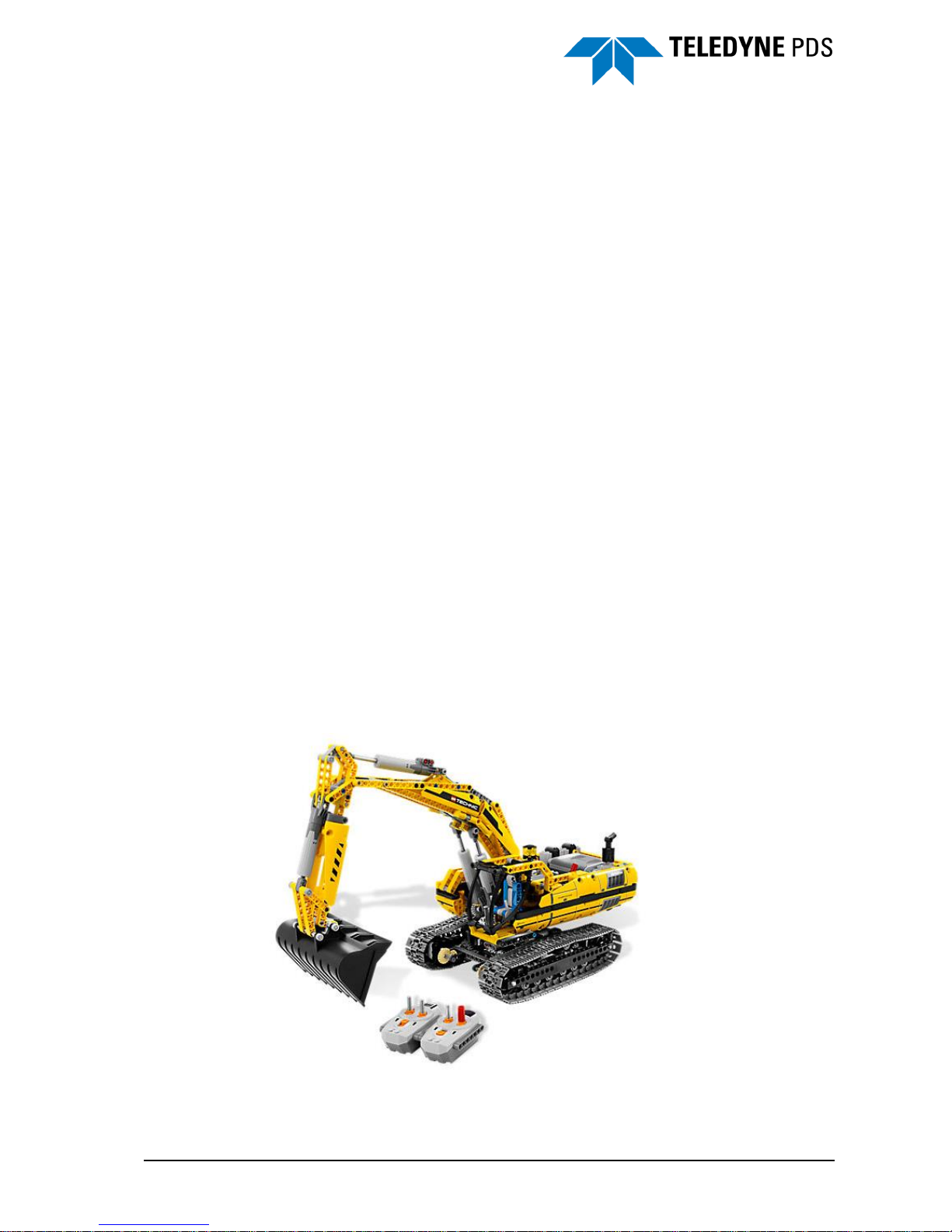
The LEGO Excavator (LEGO item 8043) is used. This excavator is equipped with
move, dig, spin and lift motorized functions.
The LEGO Excavator is constructed by the user according to the LEGO building
instructions.
Figure 2-1 LEGO Excavator
Page 8
4 LEGO Excavator preparations Teledyne PDS - LEGO Excavator
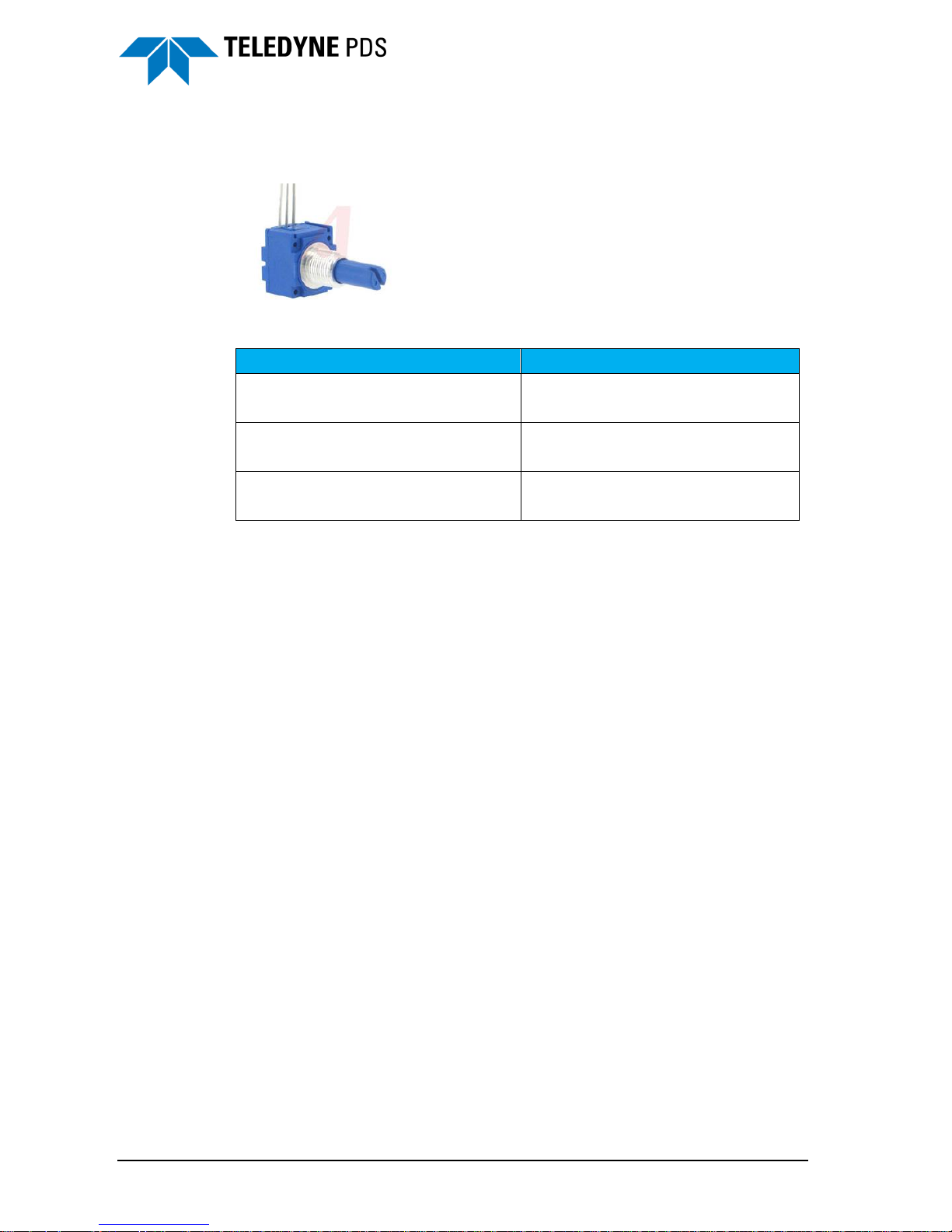
2.3 Potentiometers
To measure the boom, stick and bucket position are potentiometers used.
Figure 2-2 Potentiometer
Measure
Potentiometer
Boom
5K ohm linear
Single turn with shaft
Stick
5K ohm linear
Single turn with shaft
Bucket
5K ohm linear
Single turn with shaft
The potentiometers are mounted on the crane. The wiring is connected to the
Teledyne RESON LEGO interface.
Page 9

Teledyne PDS - LEGO Excavator LEGO Excavator preparations 5
2.3.1 Boom
The boom potentiometer is mounted on the right side of the crane chassis (see Figure
2-3, Figure 2-4.
Figure 2-3 Boom - chassis
Figure 2-4 Boom potentiometer location
The potentiometer is fixed to the chassis. The axis of the potentiometer is fixed to a
LEGO axis. The LEGO axis is fixed to the boom.
Page 10

6 LEGO Excavator preparations Teledyne PDS - LEGO Excavator
Figure 2-5 Boom axis
Figure 2-6 Axis fixed to boom.
Crane chassis
Potentiometer
Thread of
potentiometer fixed
in chassis
LEGO Axis fixed to
potentiometer axis
Crane boom
Axis fixed into
boom
Page 11

Teledyne PDS - LEGO Excavator LEGO Excavator preparations 7
2.3.2 Stick
The stick potentiometer is installed on the outer stick position on the left side of the
crane (see Figure 2-7 and Figure 2-8).
Figure 2-7 Stick potentiometer location
Figure 2-8 Stick potentiometer mounting
The potentiometer is fixed to the boom. The axis of the potentiometer is fixed to a
LEGO axis. The LEGO axis is fixed to the stick.
Page 12

8 LEGO Excavator preparations Teledyne PDS - LEGO Excavator
Figure 2-9 Connection of axis
Figure 2-10 Axis fixed to stick
Boom
Potentiometer
Thread of
potentiometer fixed
in boom
Axis fixed into
stick
Stick
Page 13

Teledyne PDS - LEGO Excavator LEGO Excavator preparations 9
2.3.3 Bucket
The bucket potentiometer is placed on the left side of the crane.
Figure 2-11 Bucket potentiometer location
The bucket potentiometer is connected to a parallelogram. The parallelogram is made
from other or spare LEGO blocks.
Figure 2-12 Potentiometer connected to support lever
Page 14

10 LEGO Excavator preparations Teledyne PDS - LEGO Excavator
Figure 2-13 Parallelogram and support lever
Figure 2-14 Drawing potentiometer connecter to parallelogram arm
The parallelogram (red colored blocks) is connected to the support lever (yellow
colored block).
Figure 2-15 Parallelogram
Stick
Potentiometer
Thread of
potentiometer fixed
in stick
Axis fixed into
arm
parallelgram
Arm
parallelogram
Stick
Parallelogram
Support
lever
Page 15

Teledyne PDS - LEGO Excavator LEGO Excavator preparations 11
Figure 2-16 Parallelogram on crane
Page 16

12 LEGO Excavator preparations Teledyne PDS - LEGO Excavator
2.3.4 Electrical connection
The potentiometers are connected to the Teledyne RESON (LEGO) interface.
The potentiometer are connected to 20VDC and to ground of the Wago 857-414
terminal and the potentiometer slider to the Wago 857-414 ‘In+’ terminal. See the
following connection diagram.
Page 17

Teledyne PDS - LEGO Excavator LEGO Excavator preparations 13
2.3.5 Potentiometer range adjustment
The Wago 857-414 terminal has an input range of 0 to 10VDC. The potentiometer is
connected to 20VDC. Therefore the potentiometer must be set in range.
To set the potentiometers in range:
1. Set the boom, stick and bucket in the center position.
Figure 2-17 Boom, stick and bucket in center position
2. Adjust the potentiometers to output 5VDC by turning the potentiometer slider.
Figure 2-18 Potentiometer position adjusted
Max
Max Max
Min
Min
Min
20VDC
GND
5VDC
Page 18

Page 19

Teledyne PDS - LEGO Excavator Drivers & Crane configuration 15
3 Drivers & Crane configuration
3.1 Introduction
Setup a PDS excavator project. See the Teledyne PDS Excavator User and the PDS
Excavator User manuals for more information about an excavator PDS project.
(Contact the Sales department of Teledyne RESON Rotterdam for a LEGO Crane
demonstration project.)
3.2 Device drivers
The following device drivers are used for the Hitachi Lego crane.
Group
Device driver
Remarks
Dredge Positioning
system
CAN LEGO Analog
Angle.dredge-backhoe
Positioning system
NMEA 2.30 GGA-GST
Using PDS Simulator to
simulate position.
Note: The remote position
device driver is added to
the pontoon equipment list
if a pontoon is used.
Compass
NMEA HDT
Using PDS Simulator to
simulate heading.
Note: The remote heading
device driver is used on the
excavator If heading is
added to the pontoon.
Attitude
Octans
Using PDS Simulator to
simulate
Bearing
Only applicable if a
pontoon is used or to
determine the crane
position with reference to
the undercarriage.
Pontoon protection
Pontoon protection Excavator
Page 20

16 Drivers & Crane configuration Teledyne PDS - LEGO Excavator
3.3 Driver properties
3.3.1 Positioning device
Set the following properties:
1. Device offset.
Location on crane.
2. Timestamp mode.
Set to computer clock if positioning is from the PDS Simulator.
Figure 3-1 Properties positioning device
3.3.2 VRU
It is not necessary to set the properties of the VRU for the demo project.
3.3.3 Compass
It is not necessary to set the properties of the compass for the demo project.
3.3.4 Dredge Positioning system
See also the next figure. Set the:
1. Device offset.
Boom pin location. For the Hitachi Lego crane this is set to X:0; Y:1.0; Z:1.0
The boom, stick and tools are configured in the Crane Configuration of the Vessel
Configuration’s Tools page.
Page 21

Teledyne PDS - LEGO Excavator Drivers & Crane configuration 17
Figure 3-2 Properties dredge positioning device
3.3.5 Crane Configuration
3.3.5.1 Boom
See also the next figure.
1. The Y offset is set to 7.5.
2. It is possible to select a custom shape or a standard shape. The standard shape is
resized automatically to the entered boom parameters.
Figure 3-3 Crane configuration - Boom
Page 22

18 Drivers & Crane configuration Teledyne PDS - LEGO Excavator
3.3.5.2 Stick
See also the next figure.
1. The Y offset is set to 2.75.
2. The Hor. Offset is set to 0.39.
3. The Z offset is set to 0.14.
4. The support lever arm is set to 0.8.
5. The driver lever length is set to 0.81.
6. It is possible to select a custom shape or a standard shape. The standard shape is
resized automatically to the entered stick parameters.
Figure 3-4 Crane configuration - Stick
3.3.5.3 Tool
See also the next figure.
1. The Y offset is set to 1.34.
2. The holes separation is set to 0.25.
3. The holes/tooth angle is set to 100.
4. The effective area width is set to 0.85.
5. It is possible to select a custom shape or a standard shape. The standard shape is
resized automatically to the entered stick parameters.
Page 23

Teledyne PDS - LEGO Excavator Drivers & Crane configuration 19
Figure 3-5 Crane configuration - Tool
Page 24

Page 25

Teledyne PDS - LEGO Excavator Index 21
Index
─ B ─
boom potentiometer - 5
bucket potentiometer - 9
─ C ─
compass - 16
connection diagram - 12
Crane Configuration - 17
─ D ─
device drivers - 15
Dredge Positioning system - 16
─ L ─
LEGO Excavator - 3
─ P ─
parallelogram - 10
Positioning device - 16
potentiometers - 4, 12
─ R ─
range - 13
─ S ─
stick potentiometer - 7
─ V ─
VRU - 16
─ W ─
Wago 857-414 - 12
 Loading...