

Page 1
9797 NXT LEGO Kit:
Basic Car Building
Instructions
© 2008 LEGOengineering.com & Tufts University Center for En gineering Educational Outreach
Page 2
NXT Basic Car Building Instructions
Table of Contents:
A. 2-Motor Car Page 3
B. 2-Motor Car Equipped With a Light Sensor Page 10
C. 2-Motor Car Equipped With a Touch Sensor Page 12
D. 2-Motor Car Equipped With a Skid ‘Wheel’ Page 14
E. 2-Motor Car Equipped With a Swivel Wheel Page 17
© 2008 LEGOengineering.com & Tufts University Center for En gineering Educational Outreach
2
Page 3
NXT Basic Car Building Instructions
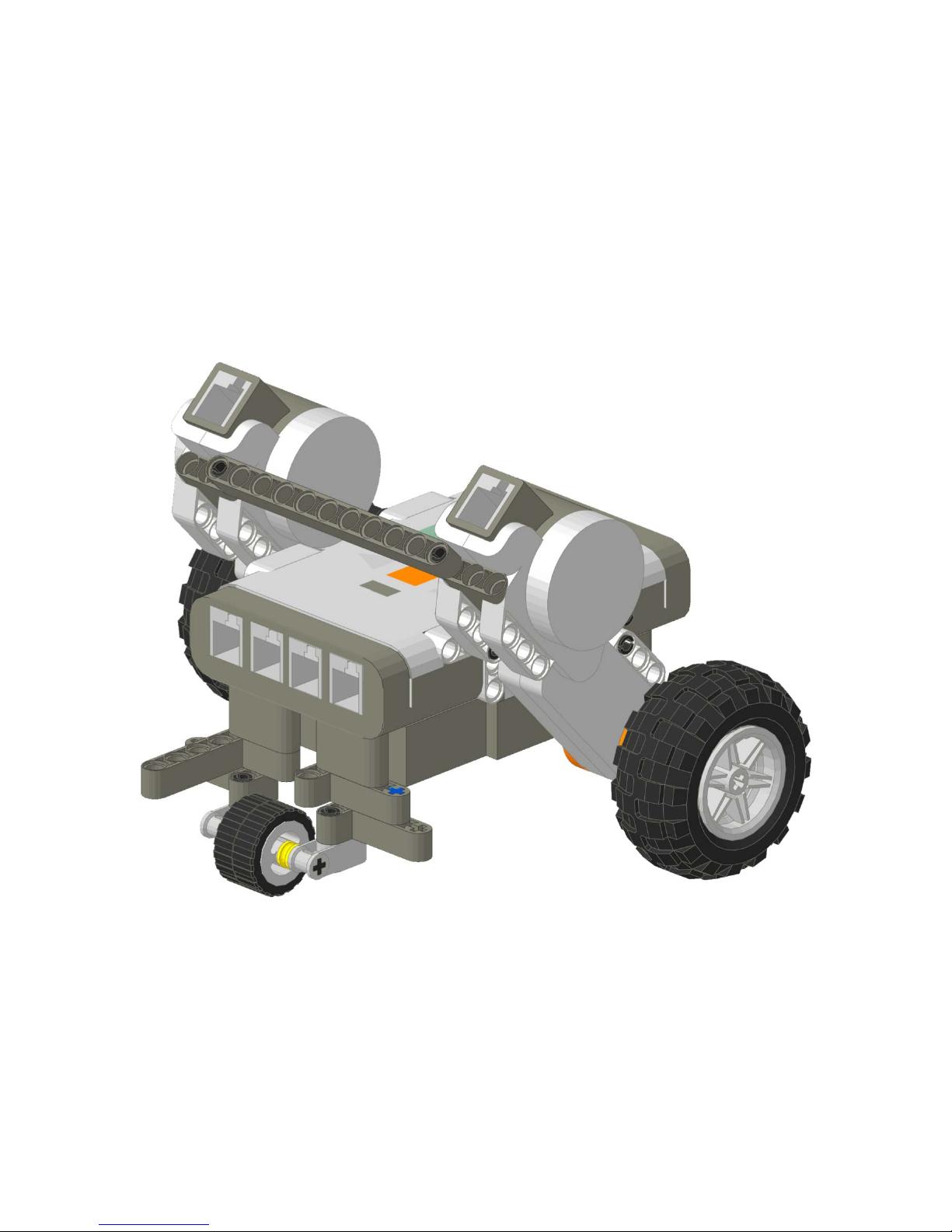
A. 2-Motor Car
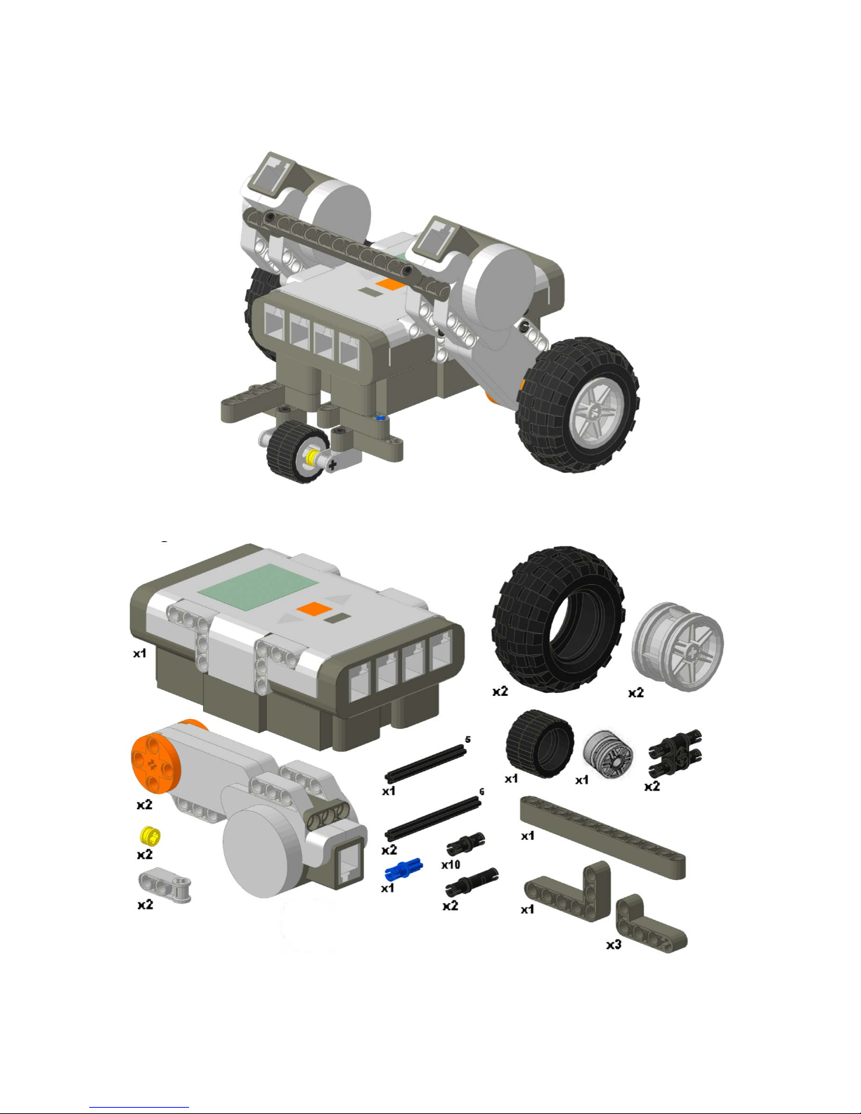
Required Pieces:
© 2008 LEGOengineering.com & Tufts University Center for En gineering Educational Outreach
3
Page 4
NXT Basic Car Building Instructions
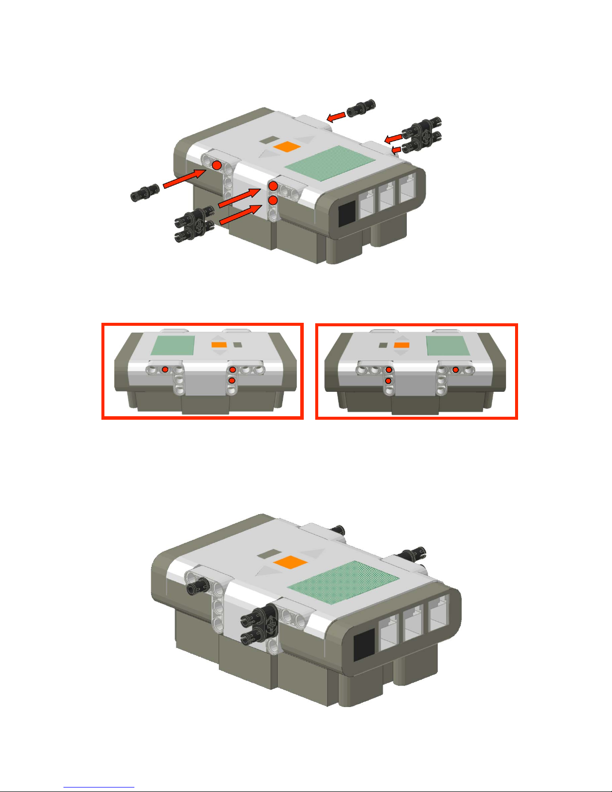
Step A.1: NXT Preparation
Side Views
Attach a double black connector peg and a single black connector peg to both sides of the
NXT. Connect the double peg vertically in the top most holes. The single peg should be
connected in the middle horizontal hole. Your NXT should look like the below picture
before moving on to the next step.
© 2008 LEGOengineering.com & Tufts University Center for En gineering Educational Outreach
4
Page 5
NXT Basic Car Building Instructions
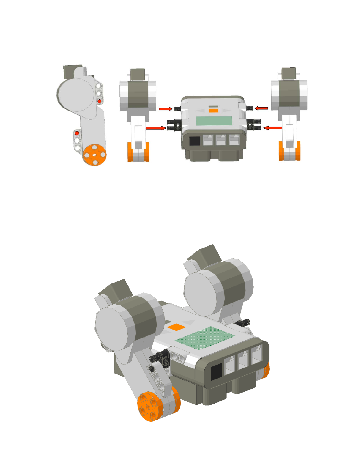
Step A.2: Attach Motors to the NXT
Side View Top View
Attach the motors (one per side) to the NXT using the double black connector pegs and
the short black connector pegs attached to the NXT. The red dots in the side view identify
which holes on the motor attach to the pegs. Your NXT should look like the below
picture before moving on to the next step.
Note: The top connection of the double black connector peg is not connected to
anything.
© 2008 LEGOengineering.com & Tufts University Center for En gineering Educational Outreach
5
Page 6
NXT Basic Car Building Instructions
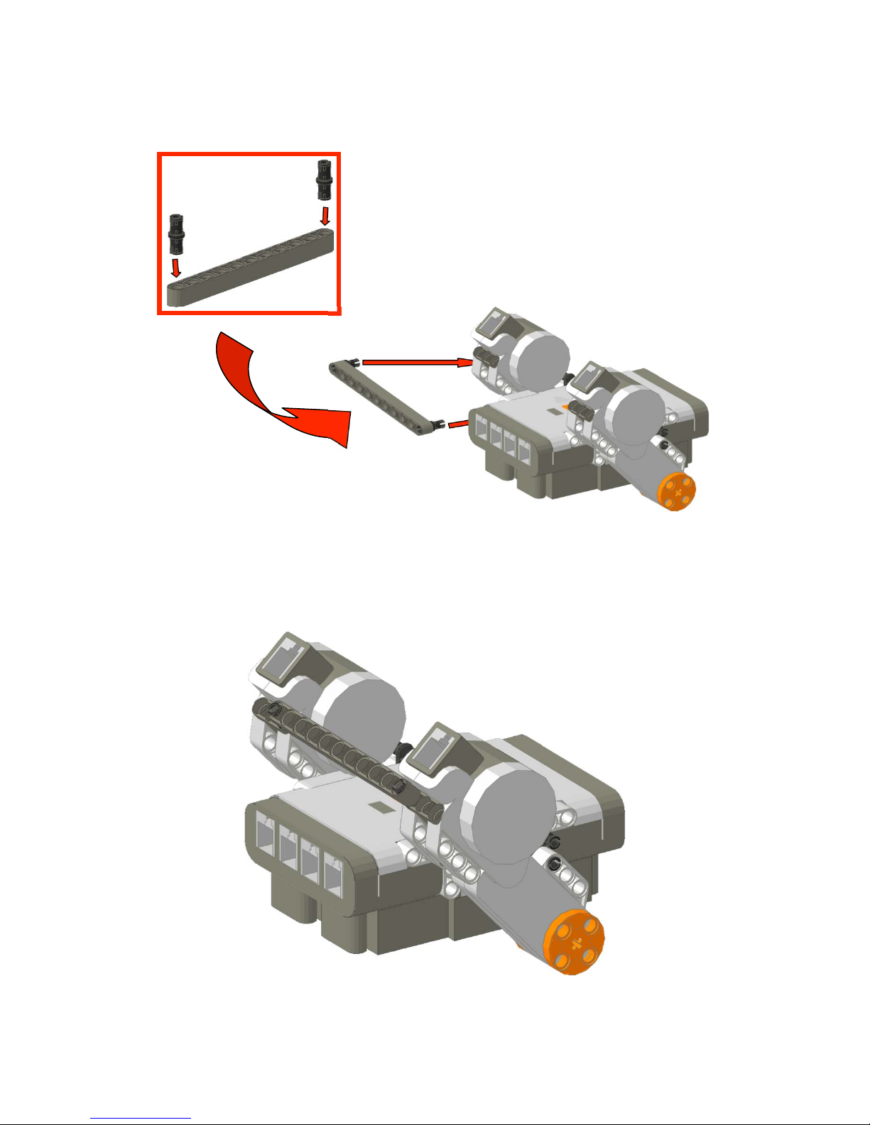
Step A.3: Support Motors
Take an 11-holed rounded beam and attach two short black connector pegs to the outside
holes as seen in the red square. Connect the pegs to the back of each motor (as identified
by the red dots) to further support the motors to the NXT. Your NXT should look like the
below picture before moving on to the next step.
© 2008 LEGOengineering.com & Tufts University Center for En gineering Educational Outreach
6
Page 7

NXT Basic Car Building Instructions
Step A.4: Attach Wheels
Assemble
to each motor as seen below.
2 rear wheel assemblies using a 6-length axle, a wheel, and a hub. Attach one
© 2008 LEGOengineering.com & Tufts University Center for En gineering Educational Outreach
7
Page 8

NXT Basic Car Building Instructions
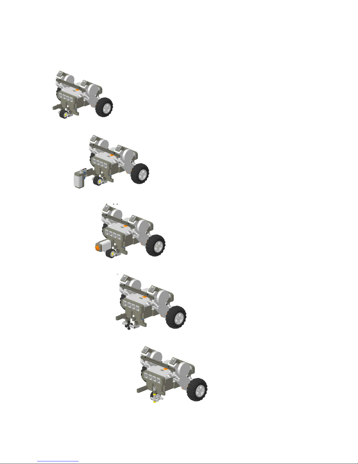
Step A.5: Front Wheel Assembly Base
Take an L-beam and attach a black connector peg to the first and third hole on the smaller
part of the L. Take a small L-beam and attach a black connector peg to the first and third
hole on the larger part of the L. In the second hole between the two connector pegs on
each L-beam, attach an extended black connector peg. Also attach a friction axel to the
fourth hole on the small L-beam. Now attach two small L-beams to the protruding pins
below the other L-beams. Attach a black connector peg to the second hole on the small
part of the L. Now attach an axel joiner on each of the protruding connector pegs below
the small L-beams. Then, align the wheel between two half bushings and slide the 5-axel
through the axel joiners.
© 2008 LEGOengineering.com & Tufts University Center for En gineering Educational Outreach
8
Page 9

NXT Basic Car Building Instructions
Step A.6: Front Wheel Assembly Attachment
Connect the front wheel assembly to the bottom of the NXT at the protruding connector
pegs.
© 2008 LEGOengineering.com & Tufts University Center for En gineering Educational Outreach
9
Page 10

NXT Basic Car Building Instructions
B. Equipped With a Light Sensor
Required Pieces:
© 2008 LEGOengineering.com & Tufts University Center for En gineering Educational Outreach
Car from Step A.6
10
Page 11

NXT Basic Car Building Instructions
Step B.1: Light Sensor Assembly
Insert a black connector peg into the first and third holes of the 5-hole beam and an
extended black connector peg into the fourth and fifth holes. Attach an axel joiner to the
extended black connector pegs. Insert a friction axel into each hole of the axel joiners
and attach the light sensor to the friction axels.
Step B.2: Attach Sensor to the Car
Attach the light sensor to the car from Step A.6. The 5-hole beam should connect to the
top of the L-beam on the front wheel assembly.
© 2008 LEGOengineering.com & Tufts University Center for En gineering Educational Outreach
11
Page 12

NXT Basic Car Building Instructions
C. Equipped with a Touch Sensor
Required Pieces:
© 2008 LEGOengineering.com & Tufts University Center for En gineering Educational Outreach
Car from Step A.6
12
Page 13

NXT Basic Car Building Instructions
Step C.1: Touch Sensor Assembly
Attach the two black connector pegs to the first and third holes of the touch sensor.
Step C.2: Attach Sensor to the Car
Attach the touch sensor assembly to the car from Step A.6. The sensor should attach to
the top of the L-beam on the front wheel assembly.
© 2008 LEGOengineering.com & Tufts University Center for En gineering Educational Outreach
13
Page 14

NXT Basic Car Building Instructions
D. Skid ‘Wheel’
Required Pieces:
Car from step A.4
© 2008 LEGOengineering.com & Tufts University Center for En gineering Educational Outreach
14
Page 15

NXT Basic Car Building Instructions
Step D.1: Skid ‘Wheel’ Assembly
Take an L-beam and attach a black connector peg to the first and third hole on the smaller
part of the L. Take a small L-beam and attach a black connector peg to the first and third
hole on the larger part of the L. In the second hole between the two connector pegs on
each L-beam, attach an extended black connector peg. Also attach a friction axel to the
fourth hole on the small L-beam. Now attach two small L-beams to the protruding pins
below the other L-beams. Attach a black connector peg to the second hole on the small
part of the L. Now attach an axel joiner on each of the protruding connector pegs below
the small L-beams. Then, align the skid ‘wheel’ between two half bushings and slide the
5-axel through the axel joiners.
© 2008 LEGOengineering.com & Tufts University Center for En gineering Educational Outreach
15
Page 16

NXT Basic Car Building Instructions
Step D.2: Attach Skid ‘Wheel’ to the Car
Connect the front skid ‘wheel’ assembly to the bottom of the NXT at the protruding
connector pegs. Follow the steps in Part B and Part C to attach sensors.
© 2008 LEGOengineering.com & Tufts University Center for En gineering Educational Outreach
16
Page 17

NXT Basic Car Building Instructions
E. Swivel Wheel
Required Pieces:
Car from step A.4
© 2008 LEGOengineering.com & Tufts University Center for En gineering Educational Outreach
17
Page 18

NXT Basic Car Building Instructions
Step E.1: Swivel Wheel Assembly
Take an L-beam and attach a black connector peg to the first and third hole on the smaller
part of the L. Take a small L-beam and attach a black connector peg to the first and third
hole on the larger part of the L. Align a bushing over the second hole on the small Lbeam. Align a half bushing followed by a bushing, 4-connector peg, and another half
bushing below the second hole on the small L-beam. Slide a 5-beam through the
bushings and connector peg. Attach a wheel to the 4-connector peg.
© 2008 LEGOengineering.com & Tufts University Center for En gineering Educational Outreach
18
Page 19

NXT Basic Car Building Instructions
Step E.2: Attach Swivel Wheel to the Car
Connect the front swivel wheel assembly to the bottom of the NXT at the protruding
connector pegs. Follow the steps in Part B and Part C to attach sensors.
© 2008 LEGOengineering.com & Tufts University Center for En gineering Educational Outreach
19
 Loading...