

Legion LGB-125 Installation Manual

Owner’s Manual
Includes the Installation, Operation, Maintenance,
and Service of Legion’s
Gas Self-Contained
Steam Jacketed Kettle
For Your Safety
Do not store or use gasoline or other flammable vapors or liquids in the vicinity of this or any other appliance. In the event a gas
odor is detected, shut down units at main shut-off valve and contact the local gas company or supplier for service.
Post in a prominent location a set of instructions to be followed in the event the user smells gas. Obtain these from your local
gas company or supplier.
Warning
Improper installation, adjustment, alteration, service or maintenance can cause property damage, injury, or death. Read the
installation, operating and maintenance instructions thoroughly before installing or servicing this equipment.
The Finest American Quality Since 1897
The Finest American Quality Since 1897
The Finest American Quality Since 1897The Finest American Quality Since 1897
LEGION INDUSTRIES, INC.♦370 MILLS RD.♦WAYNESBORO, GA 30830♦(800) 309-4895♦(706) 554-4411♦FAX: (706) 554-2035

Legion Gas Self-Contained Steam Jacketed Kettle
IMPORTANT!
Uncrating & Inspecting the Equipment
Legion Industries, Inc. is not responsible for loss or damage incurred in transit. The unit has been
assembled, tested, and inspected at the factory prior to shipment. Do not pay the freight bill until the
shipment has been thoroughly inspected!
Uncrate the equipment carefully and inspect for any damage. Also check the contents against the packing
list to make sure all accessories are included.
Important: The carrier is responsible for any shipping damage or lost parts during transit, whether visible or
concealed. You, as the recipient, are responsible for inspection and for filing all claims with the carrier.
Visible Loss/Damage: Be certain to note this on the freight or express receipt and have it signed by the
delivery person. File a claim for damages immediately, regardless of the extent of damage.
Concealed Loss/Damage: If damage is noticed after the equipment is unpacked, notify the freight company
and file a concealed damage claim. This must be done immediately. Be sure to retain the shipping
container for inspection.
i

Legion Gas Self-Contained Steam Jacketed Kettle
Table of Contents
Uncrating & Inspecting the Equipment ................................................................................................................i
Introduction ........................................................................................................................................................iv
Safety Precautions..............................................................................................................................................1
Important Warranty Information..........................................................................................................................2
Service Calls.......................................................................................................................................................3
Section I: Installation..........................................................................................................................................4
1. Positioning the Unit .....................................................................................................................................4
Fig. 1.1: Minimum Clearances................................................................................................................4
2. Draft Hood Installation .............................................................................................................................4
3. Leveling & Securing the Unit....................................................................................................................4
4. Electrical Connection ...............................................................................................................................4
5. Gas Connection.......................................................................................................................................5
Fig. 1.2: Configuration of Gas Connection..............................................................................................5
6. Checking For Gas Leaks .........................................................................................................................6
7. Gas Control - Pressure Verification .........................................................................................................6
Fig. 1.3: Pressure Regulator Specification Pressures (in Inches Water Column)..................................6
To check inlet pressure - with other equipment on the same line turned on and turned off: ......................6
To check outlet pressure - with other equipment on the same line turned on and turned off:....................7
8. Completing the "Installation Checklist" ....................................................................................................8
SECTION II: START-UP & OPERATION..........................................................................................................9
1. Initial Cleaning.............................................................................................................................................9
Removing & Cleaning the Draw-Off Valve: ...............................................................................................10
2. Lighting the Pilot ....................................................................................................................................10
3. Control Functions...................................................................................................................................10
Fig. 2.1: Control Panel Features...........................................................................................................11
Summary of Control Functions:.................................................................................................................11
Shutting Down the Unit:.............................................................................................................................11
How to Start Cooking:................................................................................................................................11
Section III: Service & Maintenance..................................................................................................................12
1. Servicing....................................................................................................................................................12
A) Replacing Primary Thermostat .............................................................................................................12
B) Replacing the Igniti on System Control..................................................................................................14
C) Replacing the Gas Burner or Burner Orifices.......................................................................................14
D) Replacing the Thermocouple and Pilot Burner Assembly....................................................................15
2. Actuator Maintenance and Adjustment..................................................................................................15
A) Actuator Tension Adjustment................................................................................................................15
B) Actuator: Re-Packing With Grease................................................................................................ .......16
Fig. 3.1: Actuator Components & Assembly.........................................................................................16
C) Actuator Replacement ..........................................................................................................................17
Fig. 3.2: Removing/Installing Actuators.................................................................................................17
3. Gas Control System..................................................................................................................................17
A). Maintenance of the Gas Control System.............................................................................................17
Fig. 3.3: VR4200A Gas Control .............................................................................................................18
Fig. 3.4: VR8304 Gas Control...............................................................................................................18
Fig. 3.5: Pilot System for the VR4200A Continuous Pilot Gas Control.................................................19
Fig. 3.6: Pilot System for the VR8304 Intermittent Pilot Gas Control ...................................................19
B) Identifying Unsatisfactory Pilot Flames.................................................................................................21
Fig. 3.7: Examples of Problem Pilot Flames.........................................................................................21
4. Filling Steam Jacket.................................................................................................................................22
Section IV: Caring For Stainless Steel ............................................................................................................23
Section V: Troubleshooting..............................................................................................................................24
1. Troubleshooting-General Problems.........................................................................................................24
ii

Legion Gas Self-Contained Steam Jacketed Kettle
2. Troubleshooting- VR420 0A Gas Control ..................................................................................................25
Fig. 5.1: The VR4200A Continuous Pilot Gas Control..........................................................................25
3. Troubleshooting—VR8304 Gas Control System ......................................................................................26
Fig. 5.2: The VR8304 Gas Control System ..........................................................................................26
Troubleshooting Chart...............................................................................................................................26
Checking the Grounding............................................................................................................................27
Checking the Ignition Cable.......................................................................................................................27
Checking and Adjusting Gas Input and Burner Ignition ............................................................................27
Section VI: Parts List .......................................................................................................................................28
1. General Parts List ....................................................................................................................................28
2. Actuator Parts List & Assembly.................................................................................................................29
Fig. 6.1: Actuator Assembly Diagram ...................................................................................................29
3. Compressio n Draw-Off P ar ts List & Assembly .........................................................................................30
Fig. 6.2: Com pr es sion Draw-O ff Assembly Diagr am............................................................................30
For Your Use & Review ....................................................................................................................................31
Installation Checklist .....................................................................................................................................31
Maintenance & Service Log ..........................................................................................................................32
Legion Limited Warranty and Extended Warranty Coverage...........................................................................33
iii
Legion Gas Self-Contained Steam Jacketed Kettle
Introduction
Congratulations on your Legion equipment purchase. This manual covers the installation, operation, and
maintenance of the Ga s Self-Contained Steam Jacketed Kettle.
This manual contains complete information. By reviewing it thoroughly and following its guidelines, your
equipment will provide you with a lifetime of dependable use.
IMPORTANT! There are three things you need to do as soon as possible after receiving and/or installing
your equipment, since they affect your warranty coverage.
1. Send in your "Warranty Registration Card." This is vital and necessary in the processing of any future
service required on your equipment.
2. Complete the "Installation Checklist," contained in this manual, at the time of installation. This is
necessary for your warranty to be valid.
3. Record the model number, serial number, and installation date for your unit and file this information for
future reference. Space for these entries is provided at the top of the "Maintenance and Service Log"
included at the end of this manual.
If, at any time, you have questions about warranty coverage, operating procedures, service, repairs, or
maintenance, contact:
Legion’s Customer Service Department
Post Office Box 728
Waynesboro, Georgia, 30830
Phone: (800) 887-1988
Fax: (706) 554-2035
Email: service@legionindustries.com
Once again we thank you for the purchase of your equipment. From its versatility, safety features, and
durable constr uction, to its time-tested performance and full HACCP comp liance, you’ve selected the finest
equipment available. We know it will provide you with reliable, efficient service for years to come.
Charles Brown
President
Legion Industries, Inc.
PS: Please visit our web site @ www.legionindustries.com
iv

Legion Gas Self-Contained Steam Jacketed Kettle
Safety Precautions
♦ Installation of the equipment must be done by a qualified technician, knowledgeable of and experienced in
the installation of commercial gas and electrical cooking equipment.
♦ Retain this manual for future reference.
Gas/Combustion Precautions
♦ Your installation must conform to local codes or in the absence of local codes, with the current National Fuel
Gas Code ANSI Z223.1 (latest edition). Do not store or use gasoline or other liquids with flammable vapors
in the vicinity of this equipment.
♦ Always disconnect the fuel source before servicing.
♦ The ignition system controls of this equipment have been factory set for either natural (manufactured) or LP
gas. Do not attempt to use an ignition system control set for natural (manufactured) gas with LP gas or an
ignition system set for LP gas with natural (manufactured) gas. Ignition system controls cannot be field
converted from one gas type to the other.
♦ It is your responsibility to post, in a prominent location, instructions to be followed in the event the user
smells gas. This information must be obtained from your local gas supplier. Until it is obtained, post the
label that came with this manual.
IMPORTANT! In the event gas odor is detected, do the following.
♦ Observe the posted instructions.
♦ Shut down the unit at the main shut-off valve.
♦ Contact the local gas company or supplier—from a phone away from the building—for emergency
service and follow the supplier’s instructions.
♦ If the gas supplier cannot be reached, call the fire department.
♦ Do not use any phone in the building.
♦ Do not light or start any appliance.
♦ Do not touch any electrical switch.
Pressure Testing Precautions on Gas Units
♦ The equipment and its indivi dual shut-off valve must be discon nected from the gas supply piping system
during any pressure testing of that system at test pressures in excess of 1/2 psig (3.45 kPA).
♦ The equipment must be isolated from the gas supply piping system by closing its individual manual shut-off
valve during any pressure testing of that system at test pressures equal to or less than 1/2 psig (3.45 kPA).
Positioning Precautions
♦ The unit must be placed on a non-combustible floor, under an e xhaust hood, with a fire retardant sy stem
and all connections and placement must comply with all applicable local and national codes. Your
ventilation hood, when installed, must conform to ANSI/UL 705 and ANSI/NFPA 96 (latest edition).
♦ Adequate make- up a ir mu st be prov id ed for e xhau st sy stem s in the ar ea where the equipment is to be
installed.
♦ No frame or restriction shall be constructed around the equipment that will restrict air movement into the
equipment's combustion area or prevent proper combustion.
♦ Adequate clearance for servicing and proper operation must be maintained.
1

Legion Gas Self-Contained Steam Jacketed Kettle
Electrical Precautions
♦ This equipment must be electrically grounded in accordance with local codes or, in the absence of local
codes, with the National Electrical Code, ANSI/NFPA No. 70 (latest edition) or the Canadian Electrical
Code, CSA C22.1 (latest edition), as applicable.
♦ The pilot flame on this equipment is lit automatically and requires electrical power to operate. Therefore,
never attempt to operate the equipment during a power failure.
General Use Precautions
♦ Always instruct employees on the proper use of this equipment.
♦ Never attempt to move this equipment when it is full of hot oil or another hot liquid.
♦ Never operate this equipment during a power failure.
♦ This equipment is intended for other than household use.
Warning & Operating Plates
♦ All warning and operating plates on the equipment should be in place at all times. If plates are damaged or
lost, replace them immediately.
Product Improvements
♦ Be aware that as continuous product improvement occurs, specifications may be changed without notice.
Important Warranty Information
The Legion Limited Warranty is valid in the Continental United States and Hawaii and is void elsewhere. A
complete statement of warranty terms and conditions is included in this manual. However, to ensure that you are
familiar with the installation, maintenance, and o ther important warranty-related conditions, please study the
following.
The instructions in this manual must be read thoroughly before attempting installation, operation, maintenance, or
service. Legion Industries, Inc. reserves the right to render void any warranty on equipment not installed in
accordance with the manual by a qualified technician, knowledgeable of and experienced in the installation of
commercial gas and electrical cooking equipment.
Legion products are built to comply with applicable standards of manufacturers. Many local codes exist and it is the
responsibility of the equipment owner and installer to comply with these codes.
If the equipment has been changed, altered, modified, or repaired by other than a qualified service technician
during or after the one year limited warranty period, Legion Industries, Inc. shall not be liable for any incidental or
consequential damages to any person or to any property which may result from the use of the equipment
thereafter.
The Limited Warranty does not extend to:
1. Installation and start-up. Proper installation is the responsibility of the owner/installer. Repair services for the
same will not be covered.
2. Malfunction as a result of improper maintenance.
3. Failure as a result of improper use or abuse of equipment.
4. Repair services initiated without prior authorization from Legion.
5. Repair services for problems caused by inadequate gas supply pressure or low voltage supply.
6. Repairs made by anyone other than qualified service personnel recommended by Legion.
7. Damage caused in shipment.
8. Repair services for problems caused by routine maintenance or cleaning.
9. Damage caused by tampering with, removing, or changing a preset control or safety device.
2

Legion Gas Self-Contained Steam Jacketed Kettle
10. Damage caused by hitting the cooking surface with implements or by rubbing or scraping the cooking surface
with abrasive materials.
11. Damage caused by simple adjustments, such as actuator adjustments.
12. Lubrication of grease fittings or actuator springs and gears. These parts should be greased at least once
every six months.
13. Moving other equipment to gain access to the unit.
14. Damages to any part of the unit as a result of cleaning with high-pressure water or steam. Do not spray the
exterior of the equipment with water or steam!
15. Use of any replacement parts other than those supplied or authorized by Legion voids all warranties and can
cause bodily injury to the operator and damage to the equipment.
Refer to your warranty statement for those items that are covered for only a 90-day period.
Service Calls
All repair services under Legion’s Limited Warranty must be authorized in advance by Legion or performed by
Legion. Authorization may be obtained by calling:
(800) 887-1988
(within the Continental U.S. and Hawaii)
8 a.m. through 5 p.m. (EST), Monday through Friday
When calling, please have the following information available:
♦ name, address, and teleph one number of the end-user;
♦ location of the product;
♦ name, model number, and serial number of the product;
♦ description of the problem or defect.
Legion will then issue a service authorization work order number to one of its approved independent servicing
organizations or request that the product or part be shipped to Legion for repair or replacement, as appropriate.
Any defective part subject to a claim under the Limited Warranty must be shipped freight prepaid to Legion for
testing and examination. Legion’s decision as to the cause and nature of any defect under this Limited Warranty
shall be final.
3
Legion Gas Self-Contained Steam Jacketed Kettle
Section I: Installation
IMPORTANT! Installation of the equipment must be done by a qualified technician, knowledgeable of and
experienced in the installation of commercial gas and electrical cooking equipment. It is the responsibility of the
owner and installer to comply with all applicable local and national codes and regulations when installing the unit.
All internal wiring of the equipment is supplied complete and ready for final connection. A wiring diagram is
supplied behind the cover of the unit’s control console. Legion's Engineering Department must approve any
mechanical or electrical changes.
1. Positioning the Unit
WARNING:
• The unit must be placed on a non-combustible floor, under an exhaust hood, with a fire retardant system and all
connections and placement must comply with all applicable local and national codes. Your ventilation hood,
when installed, must conform to ANSI/UL 705 and ANSI/NFPA 96 (latest edition).
• Adequate make-up air must be provided for exhaust systems in the area where the equipment is to be installed.
• No frame or restriction shall be constructed around the equipment that will restrict air movement into the
equipment's combustion area or prevent proper combustion.
• Adequate clearance for servicing and proper operation must be maintained
Position the unit where you intend to use it. A minimum of fifteen (15) inches must be provided for servicing of
controls. Remember to also consider the required clearances of any other adjoining pieces of equipment.
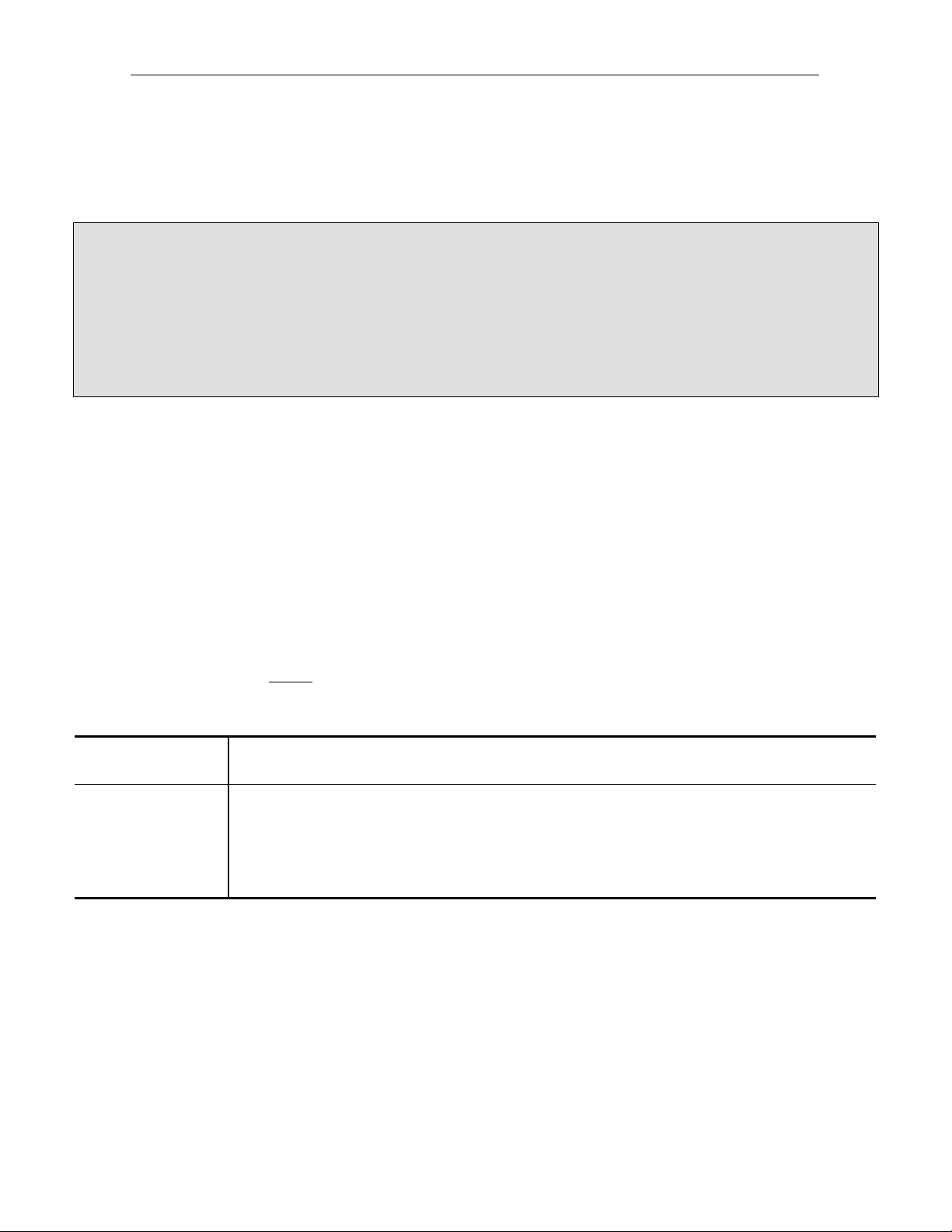
Fig. 1.1: Minimum Clearances
Model Back of Unit Sides of Unit Draft Hood
LGB, LGBE 6” 6" 2”
2. Draft Hood Installation
Warning:
This unit is not suitable for connection to Type B gas vent. It is recommended that flue gases be vented to a
ventilating hood or directly to the atmosphere (outside air).
Connect furnished draft hood to the kettle flue outlet. All units have seven (7) inch diameter flue outlet with the
exception of the LGB/E 20, which has a six (6) inch diameter flue outlet.
3. Leveling & Securing the Unit
The feet of the unit may be adjusted so that the kettle is properly leveled.
4. Electrical Connection
WARNING:
• This equipment must be electrically grounded in accordance with local codes or, in the absence of local codes,
with the National Electrical Code, ANSI/NFPA No. 70 (latest edition) or the Canadian Electrical Code, CSA
C22.1 (latest edition), as applicable.
4
Legion Gas Self-Contained Steam Jacketed Kettle
• Also, it is required that an electrical cut-off device, such as a fused disconnect switch or equivalent, be installed
in the power supply line between the main power supply and the unit.
• The pilot flame (LGBE only) on this equipment is lit automatically and requires electrical power to operate. The
unit will not operate if the power is off.
• The pilot flame (LGB only) on this equipment is lit manually and requires electrical power to operate. The unit
will not operate if the power is off.
A power cord is provided on the back of the unit, for connecting to the electric power supply. The installer should
verify the electrical requirements of the unit to make sure your power supply line is capable of powering the
equipment properly. This information is listed on the unit’s nameplate.
• Standard 120 Volt Model: Connect a 120 volt, 60 Hz, single (1) phase power cord.
• Optional 240 Volt Model: Connect a 240 volt, 60 Hz, single (1) phase power supply at the junction box.
5. Gas Connection
WARNING:
• Your installation must conform to local codes or in the absence of local codes, with the current National Fuel Gas
Code ANSI Z223.1 (latest edition), the Natural Gas Installation Code, CAN /CGA-B149.1 (latest edition), o r the
Propane Installation Code, CAN/CGA- B149.2 (latest edition), as appli cable.
• Do not store or use gasoline or other liquids with flammable vapors in the vicinity of this equipment.
• Always disconnect the fuel source before servicing.
• The ignition system controls of this equipment have been factory set for either natural (manufactured) or LP gas.
Do not attempt to use an ignition system control set for natural (manufactured) gas with LP gas or an ignition
system set for LP gas with natural (manufactured) gas. Ignition system controls cannot be field converted from
one gas type to the other.
• It is your responsibility to post, in a prominent location, instructions to be followed in the event the user smells
gas. This information must be obtained from your local gas supplier.
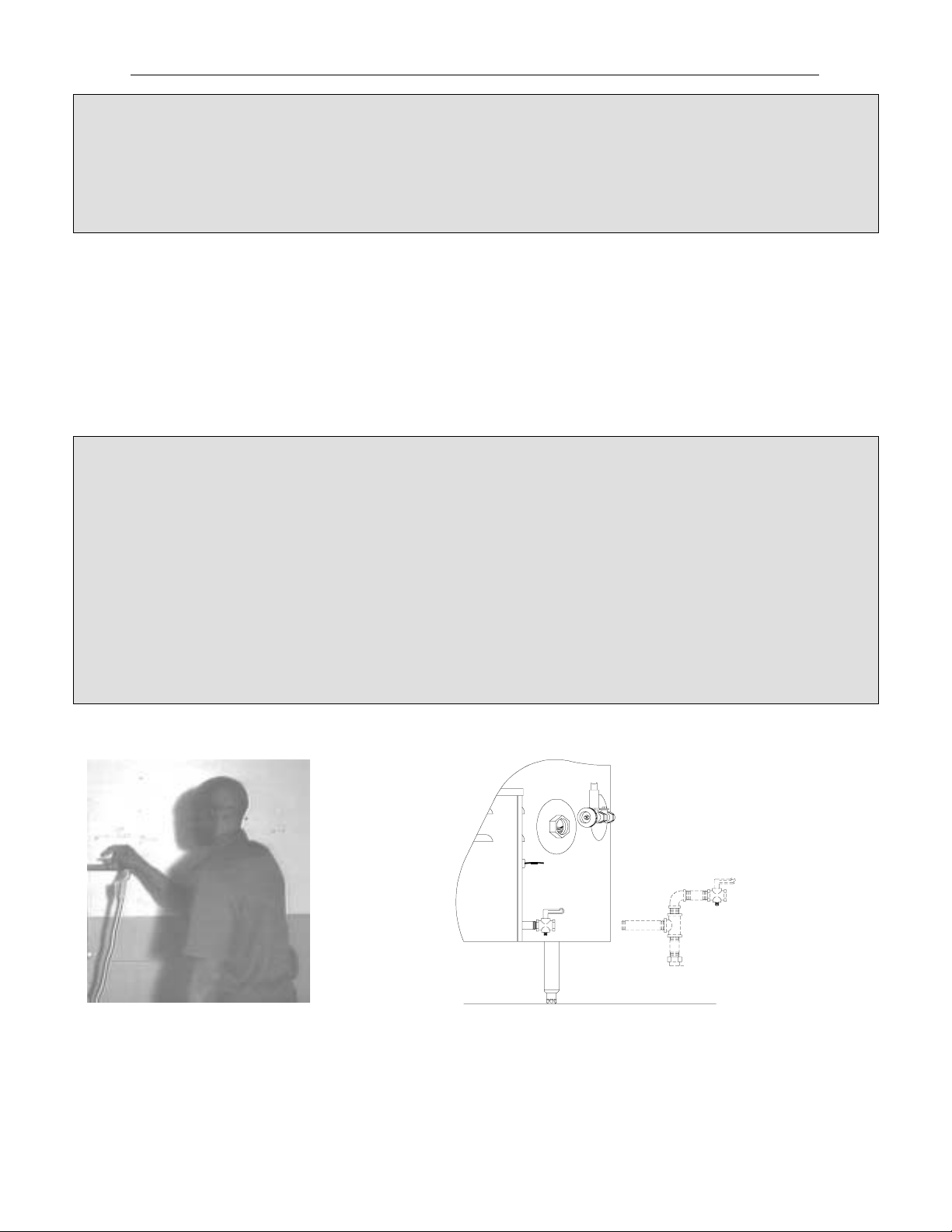
Fig. 1.2: Configuration of Gas Connection
1. Shut off the main gas supply
before beginning the gas
connection.
2. Properly configure the gas supply line to be used (see Fig. 1.2). The gas
supply line must be a minimum of 3/4" NPT pipe. It is your responsibility to
ensure that the supply line installed is large enough to achieve the proper
pressure and allow the required volume of gas to flow. A sediment trap must
be installed to protect against contamination of the ignition system control.
Install a manual shut-off valve between the gas supply line and the sediment
trap to allow for maintenance of the trap.
5
Legion Gas Self-Contained Steam Jacketed Kettle
In making the connections, use a good quality joint compound. If LP gas is supplied, a joint compound resistant to
LP gas should be used. Connect the supply line to the ball valve at the rear of the unit. Tighten the connection
securely.
6. Checking For Gas Leaks
WARNING:
• Do not permanently supply gas to the unit until the gas lines have been pressure tested. Faulty operation and
even equipment damage will result if the gas supply falls below requirements.
• The eq uipme nt and its individual shut-off valve must be disconnected from the gas supply pipi ng system during
any pressure testing of that system at test pressures in excess of 14 inch water column (or 1/2 psig or 3.45 kPA).
• The equipment must be isolated from the gas supply piping system by clo sing its individual manual shut-off valve
during any pressure testing of that system at test pressures equal to or less than 14 inch water column (or 1/2
psig or 3.45 kPA).
1. Turn on the main gas supply. With burner off, douse the pipe connections upstream of the ignition system
control with a rich soap and water solution. Bubbles indicate a gas leak. If a leak is detected, tighten pipe
connections. Replace the part if the leak cannot be stopped.
2. With main burner in operation, douse pipe joints and control inlet and outlet with rich soap and water solution.
If another leak is detected, tighten joints and pipe connections. Replace the part if the leak cannot be stopped.
7. Gas Control - Pressure Verification
Using a pressure gauge or a manometer, the installer must record the gas pressure at both the inlet and outlet of
the ignition system control—first with all equipment on the same gas line turned on, then with all equipment turned
off. These readings are necessary for your installation and warranty records. Gas pressure input and output
ratings for your equipment are listed on the unit’s nameplate. Acceptable pressure ranges are provided below. Do
not exceed these ratings. NOTE
must be checked first.
Fig. 1.3: Pressure Regulator Specification Pressures (in Inches Water Column)
Gas Valve Type Type of Gas Nominal Inlet Pressure
Standing Pilot Natural
Intermittent Pilot Natural
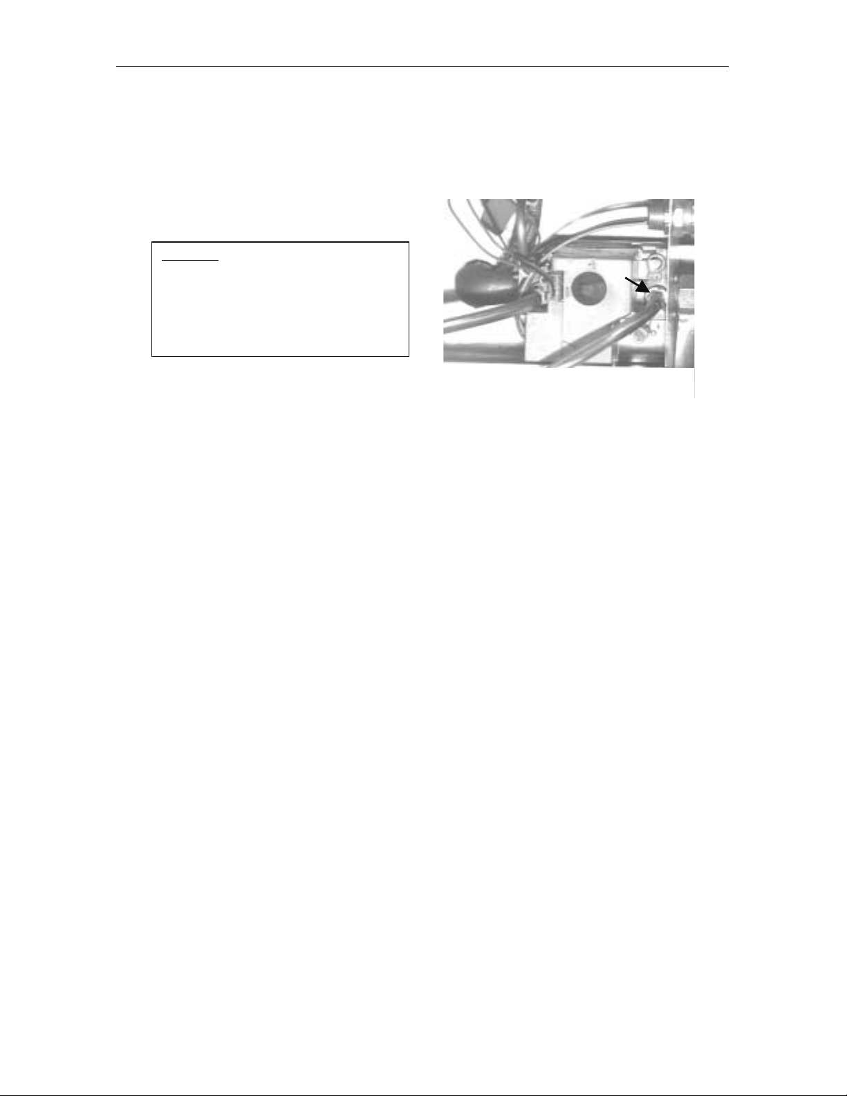
To check inlet pressure - with other equipment on the same line turned on and turned
off:
Check the inlet pressure with all equipment on the same gas supply line turned on and turned off.
Note: See Fig. 3.3 or Fig. 3.4 in Section III for a close-up view of the ignition system contro l and its components.
: Since outlet pressure is dependent upon proper inlet pressure, inlet pressure
LP
LP
Range
5.0—7.0" W.C.
12.0—14.0" W.C.
5.0—7.0" W.C.
12.0—14.0" W.C.
Factory Set Nominal Outlet
Pressure
3.5" W.C.
10.0" W.C.
3.5" W.C.
11.0" W.C.
Adjustment Setting
Range
3—5
8—12
3—5
8—12
1. Shut off the gas supply and remove the cover panel of the control console. Remove the inlet pressure tap and
connect the pressure gauge or manometer.
2. Turn the gas supply back on. Light the main burner. The main burner is lit by turning the primary thermostat
dial above room temperature. Note, in the case of standing pilot, you must first light the pilot. For instructions
on lighting the pilot refer to Section II, Startup and Checkout.
6
Legion Gas Self-Contained Steam Jacketed Kettle
3. Record the inlet pressure readings on the Installation Checklist for Warranty Validation. Be sure to take
readings with other equipment on the same line turned on and turned off.
4. Reverse the procedure in step 2 to turn off the main burner and shut off the gas supply before disconnecting
the manometer or pressure gauge.
Important!Always shut off the gas supply
at the manual valve in the gas supply
piping to the unit (or at the tank for LP
gas), before removing the inlet pressure
tap plug to connect or disconnect a
pressure gauge or manometer.
5. Replace the inlet pressure tap plug.
Inlet Pressure Too High? If natural gas pressure exceeds 7" water column or LP gas pressure exceeds 14"
water column, then a pressure-regulating valve must be installed in the gas supply line.
Inlet Pressure Too Low? If natural gas pressure is below 5" water column or LP gas pressure is below 12" water
column, then the installer must determine the problem. Too much equipment may be on the same line or a
larger gas supply line may be required.
Inlet pressure must be correct before checking the outlet pressure.
To check outlet pressure - with other equipment on the same line turned on and turned
off:
Check the outlet pressure with all equipment on the same gas supply line turned on.
1. Be sure the ignition system control knob is in the OFF position. Remove the outlet pressure tap plug and
connect the pressure gauge or manometer. Turn the ignition system control knob to the ON position.
2. Turn the gas supply back on and light the main burner by following Step 2 in the previous procedure for
checking the inlet pressure.
3. Record the outlet pressure readings by following Step 3 in the Check inlet pressure procedure for checking the
inlet pressure.
4. Turn OFF the main burner and shut off the gas supply before disconnecting the manometer or pressure gauge
by reversing the procedure in Step 2 in the previous procedure for checking the inlet pressure.
7
 Loading...