

Leggett & Platt Performance Pro-motion Queen, Performance Pro-motion Split Cal-King Owner's Manual
owners manual
PRO-MOTION
ENGLISH
SPANISH
FRENCH
*Queen
*Split Cal-King
LPAdjustableBases.com


CONTENTS
Advisory ...................................................................................................................... 4
Acoustics .................................................................................................................... 6
Fabric Cleaning Information .......................................................................................... 6
Installation ................................................................................................................. 7
Remote Control Function ............................................................................................ 14
Troubleshooting ......................................................................................................... 15
Accessories ............................................................................................................... 16
Dual DC Connector Cable (optional accessory) .............................................................. 17
1-3-25 Warranty ........................................................................................................ 21
Spanish translation begins on page 23.
La traducción en español inicia en la página 23.
French Canadian translation begins on page 43.
La traduction en Français débute à la page 43.
If adjustable base does not operate or if parts are missing, call:
800-888-3078
Do not contact retail store or dealer.

ADVISORY
WARNINGWARNING
IMPORTANT INFORMATION
READ THE FOLLOWING INFORMATION CAREFULLY BEFORE USING THIS PRODUCT
PRODUCT RATINGS
The base lift motors are not designed for
continuous use. Reliable operation and full
FOR OPTIMUM ADJUSTABLE BASE
OPERATION, USE A GROUNDED, ELECTRICAL
SURGE PROTECTION DEVICE (NOT
INCLUDED). FAILURE TO USE A SURGE
PROTECTION DEVICE COULD COMPROMISE
SAFETY OR CAUSE PRODUCT MALFUNCTION.
life expectancy will be realized as long as the
lift motor operation does not exceed five (5)
minutes over a forty-five (45) minute period,
or approximately 11% duty cycle. Any attempt
to circumvent or exceed product ratings will
shorten the life expectancy of the product and
may void the warranty.
ELECTRICAL RATING
Electrical components are rated for 110/120
voltage, 60Hz, 100 watt.
ELECTRICAL GROUNDING
This product is equipped with a polarized or
grounded electrical power cord. The power cord
will only fit into a grounded, electrical surge
protection device (not included) or a grounded
electrical outlet.
WARRANTY WARNING
Do not open any control boxes, motors or
remote control devices (with the exception
of the remote control battery compartments).
The product warranty will be void if these
components are tampered with. Do not attempt
to alter component wiring or adjust or modify
the structure of the product in any way or the
warranty will be void. Any repair or replacement
of base parts must be performed by authorized
personnel.
The recommended maximum weight (including
mattress) is 550 lb (249 kg) distributed evenly
across the base. This product is not designed
to support or lift this amount in the head
or foot sections alone. Note: Exceeding the
recommended weight restrictions could damage
the base and void the warranty.
For best performance, consumers should enter
and exit the adjustable base with the base in
the flat (horizontal) position. Avoid placing
entire weight on head or foot section of the
base, including when in the raised position. DO
NOT STAND ON BASE AT ANY TIME.
UL (Underwriters Laboratories) recognized
components.
CFR 1633 approved for use with most
mattresses.
Assembled in USA.
LUBRICATION
This product is designed to be maintenance free.
The lift motors are permanently lubricated and
sealed—no additional lubrication is required.
Do not apply lubricant to lift motor lead screws
or any nylon nuts or the base may inadvertently
creep downward from the elevated position.
Performance Models Pro-motion Owners Manual 99301466-b
4

ADVISORY
IMPORTANT INFORMATION
READ THE FOLLOWING INFORMATION CAREFULLY BEFORE USING THIS PRODUCT
SMALL CHILDREN / PETS WARNING
After the base is unboxed, immediately dispose
of packaging material as it can smother small
children and pets. To avoid injury, children or
pets should not be allowed to play under or on
the base. Children should not operate this base
without adult supervision.
PACEMAKER WARNING
This product produces a vibrating sensation.
It is possible that individuals with heart-assist
pacemakers may experience a sensation similar
to exercise. Consult physician for complete
information.
HOSPITAL USE DISCLAIMER
This base is designed for in-home use only. It
is not approved for hospital use and does not
comply with hospital standards. Do not use this
base with tent type oxygen therapy equipment,
or use near explosive gases.
SERVICE REQUIREMENTS
Service technicians are not responsible for
moving furniture, removing headboards and
footboards or any items required to perform
maintenance on the base. In the event the
technician is unable to perform service due
to lack of accessibility, the service call will be
billed to the purchaser and the service will have
to be rescheduled.
Performance Models Pro-motion Owners Manual 99301466-b
5

ACOUSTICS
LIFTING/LOWERING MECHANISMS
The lift/lower feature will emit a minimal
humming sound during operation. This is
normal.
During operation, the lift arm wheels make
contact with the platform support of the base.
This applies slight tension on the moving
components and resonance is reduced to a
minimum level. If excessive noise or vibration is
experienced, reverse the movement action (up or
down) of the base with the remote control. This
should realign the base’s activating mechanisms
to the proper operational position.
FABRIC CLEANING INFORMATION
Spot clean only with water based shampoo
or foam upholstery cleaner. Pretest a small,
inconspicuous area before proceeding. Do
not over wet. Do not use solvents to spot
clean. Pile fabrics may require brushing with
a non-metallic, stiff bristle brush to restore
appearance. Hot water extraction or steam
cleaning is not a recommended cleaning
method.
To prevent overall soiling, frequent vacuuming
or light brushing with a non-metallic stiff
bristle brush to remove dust and grime is
recommended. When cleaning a spill, blot
immediately to remove spilled material. Clean
spots or stains from the outside to the middle
of the affected area to prevent circling. Use a
professional furniture cleaning service when an
overall soiled condition is apparent.
Performance Models Pro-motion Owners Manual 99301466-b
6
INSTALLATION
For installation and setup, complete the following procedures, in the order indicated below
and on the following pages:
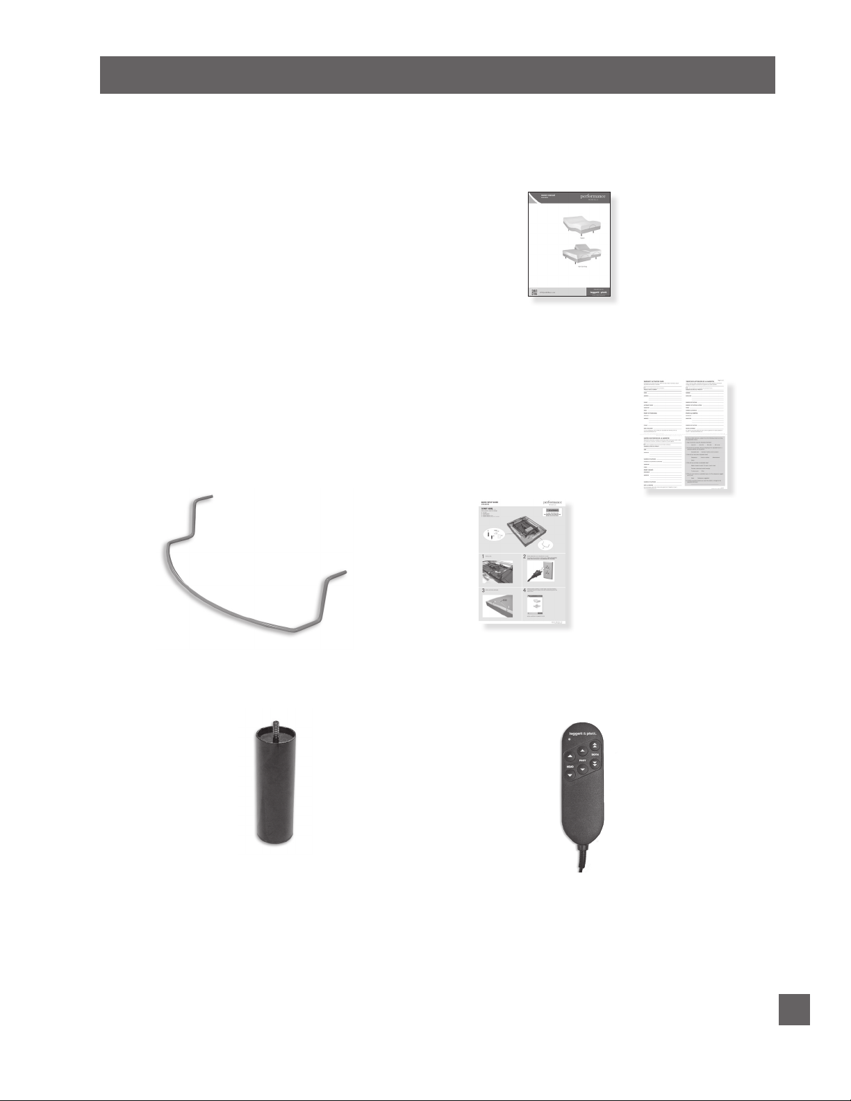
STEP 1
Before discarding any packing materials,
open the adjustable base shipping carton
and verify the following items are
included:
• (1) Mattress Retainer
• (4) Bed Legs
• (1) Remote Control
• (1) Owners Manual
• (1) Warranty Activation Card
• (1) Quick Setup Guide
OWNERS MANUAL
MATTRESS
RETAINER
(1 per base)
LEG
(4 pieces - 7” tall,
1.5” O.D.)
WARRANTY
ACTIVATION CARD
QUICK SETUP GUIDE
REMOTE CONTROL
Performance Models Pro-motion Owners Manual 99301466-b
7

INSTALLATION
WARNINGWARNING
WARNINGWARNING
CAUTIONCAUTION
STEP 2
Remove the hardware box. Cut the zip-tie and
remove the mattress retainer.
STEP 3
Install (4) legs into the base frame. Simply screw each leg
into a tapped hole at the corner of the base frame (FIGURE 1).
FIGURE 1
LEGS – SCREW INTO
TAPPED HOLE AT
EACH CORNER
TAPPED
HOLE
AT LEAST TWO PEOPLE ARE
RECOMMENDED FOR HANDLING AND
MOVING ADJUSTABLE BASE.
DO NOT ATTEMPT TO SCREW
LEGS INTO ANY OTHER INSERTS.
THIS WILL DAMAGE PRODUCT.
STEP 4
Carefully lift the adjustable base from the shipping carton,
keeping the unit top-side-down. Remove and extend out
power cord from the protective packaging.
POWER CORDS MUST NOT INTERFERE WITH
ANY ADJUSTABLE BASE MECHANISMS.
STEP 5
Remove the plastic packaging from the base frame. Carefully
rotate the adjustable base over to position the base so it is
resting on its legs.
Performance Models Pro-motion Owners Manual 99301466-b
8
INSTALLATION
STEP 6
Plug electrical power cord into a working, grounded electrical outlet.
Note: An electrical surge protection device is recommended (not included).
STEP 7
Briefly activate all functions of the base with the remote control to verify
all features are in working order. If base does not operate, refer to the
Troubleshooting section of this manual.
STEP 8
Return base to the level position.
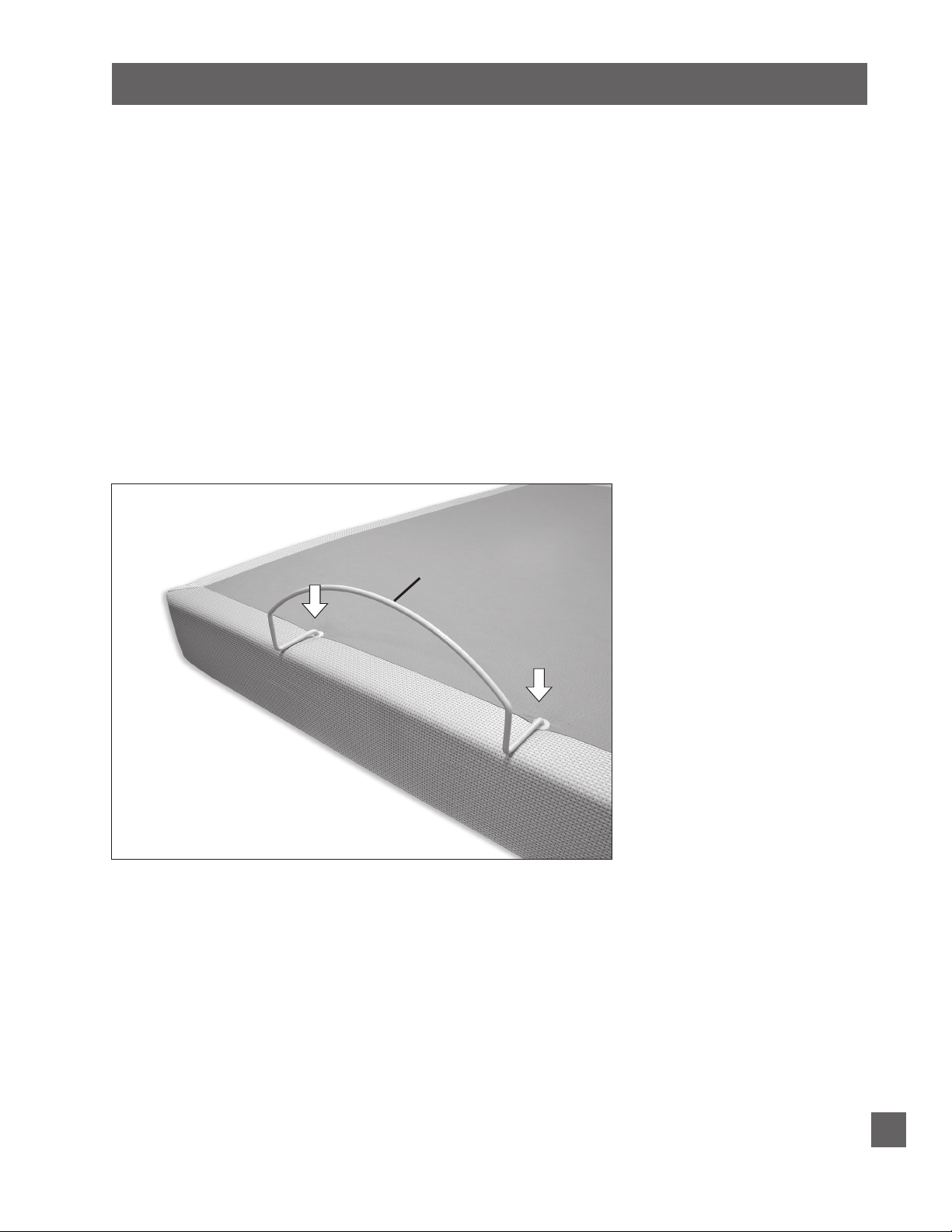
STEP 9
Install mattress retainer at the foot end of the adjustable base as follows:
a. Locate grommeted holes at foot end of base.
b. Place mattress retainer ends into grommeted holes in top surface
of adjustable base (FIGURE 2). Press down until horizontal retainer
section is flush against base.
FIGURE 2
MATTRESS
RETAINER
FOOT END OF BASE
NOTE: If base is to be set up without a headboard, install
mattress to complete basic installation. If headboard
is to be installed, proceed to Headboard Bracket
Installation. (Headboard Bracket sold as accessory.)
Performance Models Pro-motion Owners Manual 99301466-b
9
INSTALLATION
WARNINGWARNING
HEADBOARD BRACKET INSTALLATION (optional accessory)
Install headboard brackets to the base frame. When attaching (2) twin size
units to a king size headboard an optional swing hinge kit (see accessory
section) may be used to connect the twin units.
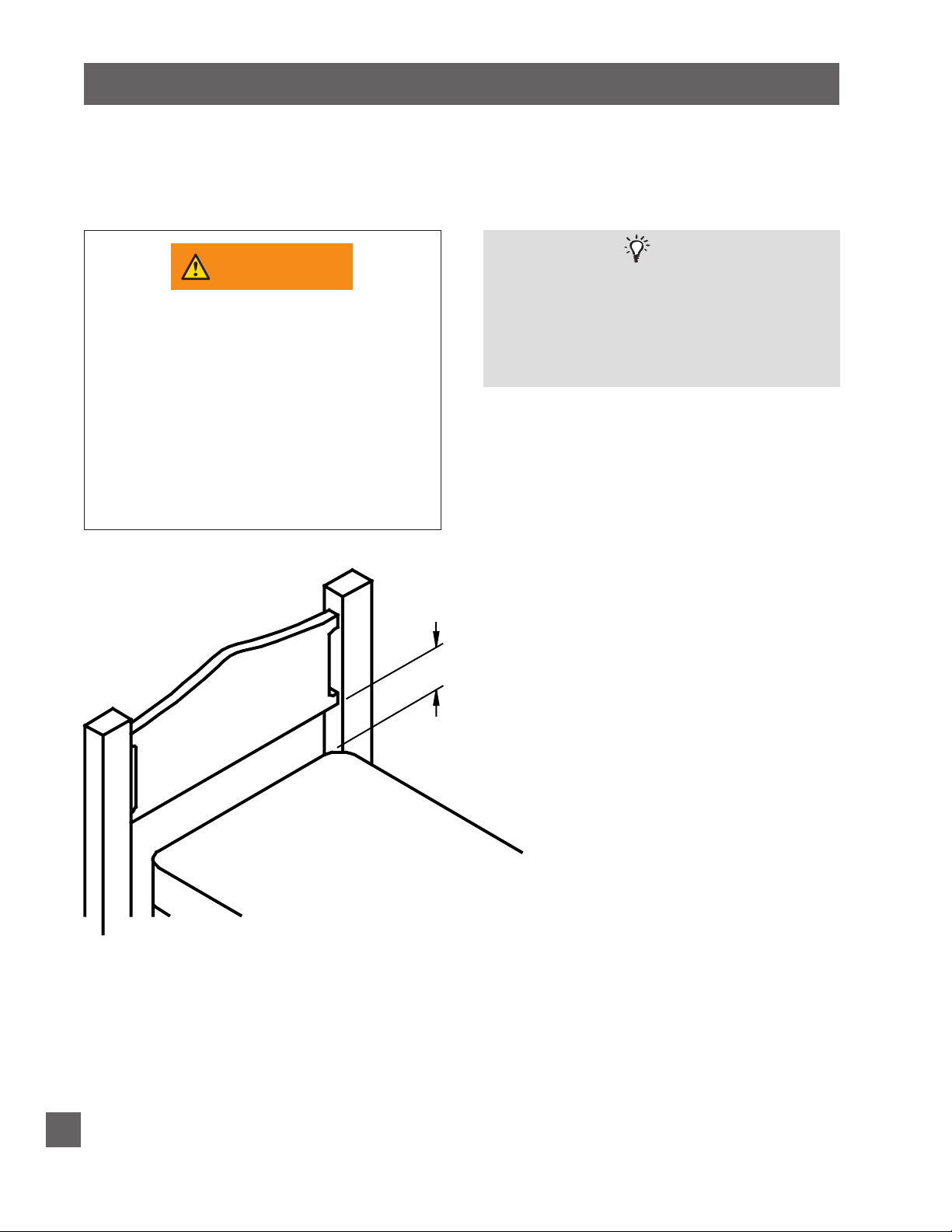
FAILURE TO FOLLOW HEADBOARD BRACKET
IN ORDER TO AVOID A PERSON OR PET
BEING CAUGHT IN THE SPACE REFERENCED
BELOW WHILE THE BED IS IN MOTION,
THE BOTTOM OF THE HEADBOARD CROSS
MEMBER MUST BE POSITIONED SO THAT
THERE IS NO MORE THAN 3 INCHES
(76.2MM) BETWEEN THE HEADBOARD AND
THE TOP OF THE MATTRESS (FIGURE 3). DO
NOT EXCEED 3 INCHES (76.2MM). FAILURE
TO FOLLOW THIS INSTRUCTION COULD
RESULT IN SERIOUS PERSONAL INJURY OR
DEATH.
INSTALLATION INSTRUCTIONS MAY CAUSE
HEADBOARD BRACKET INTERFERENCE WITH
BASE FOAM DURING BASE OPERATION.
BASE FOAM OR BASE COVER DAMAGE
COULD RESULT.
NOTE
FIGURE 3
.
3 inches MAX
Headboard cross member location
must not exceed 3 inches (76.2mm)
from the top of the mattress.
10
Performance Models Pro-motion Owners Manual 99301466-b
INSTALLATION
STEP 10
Install headboard brackets to the base frame as follows:
a. Raise the head section of the base (with remote control) to gain access
to the base frame.
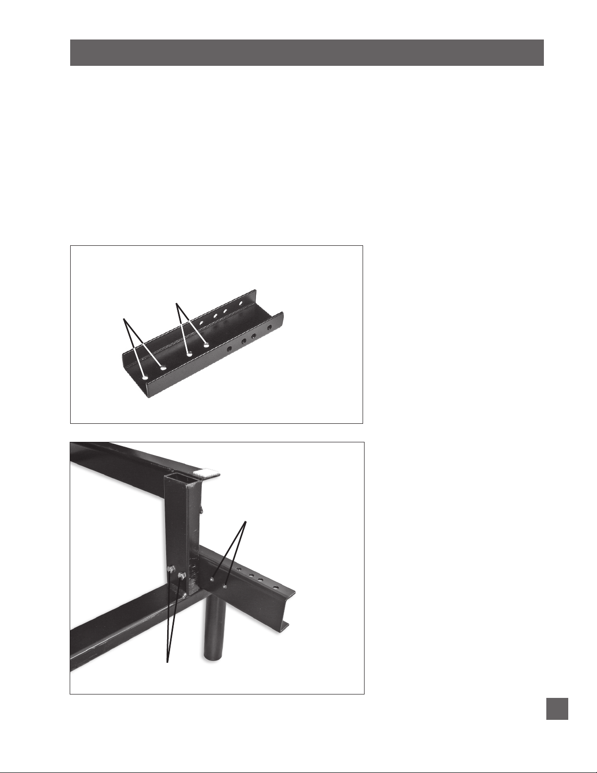
b. Locate channel connector kit (FIGURE 4). On one side of base frame,
locate (2) holes for channel connector mounting (FIGURE 5).
c. Position channel connector so that the flat side is flush against base
frame. Attach channel connector to base frame using (2) 1½ inch long
hex head bolts/nuts (FIGURE 5). Tighten bolts. Note: For units with
74” base length, use inner mounting holes. For units with 80” base
length, use outer mounting holes (FIGURES 4 and 5).
FIGURE 4
74” BASE
80” BASE
LENGTH
MOUNTING
HOLES
LENGTH
MOUNTING
HOLES
FIGURE 5
(2) 1-1/2 INCH LONG
HEX HEAD BOLTS/NUTS
74” BASE
LENGTH
MOUNTING
HOLES
Performance Models Pro-motion Owners Manual 99301466-b
11
INSTALLATION
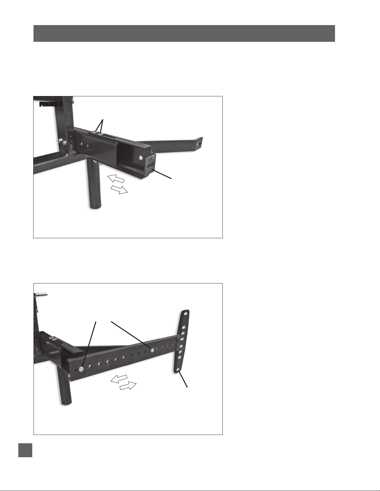
d. Using (2) 3 inch long carriage bolts/nuts, attach (1) headboard
bracket channel to (1) channel connector (FIGURE 6). Hand tighten
bolts/nuts (loosely) to allow adjustment of the headboard bracket
channels.
FIGURE 6
USE (2) 3 INCH LONG CARRIAGE
BOLTS TO ATTACH HEADBOARD
BRACKET CHANNEL TO BASE FRAME
HEADBOARD
BRACKET
CHANNEL
(queen size
shown)
SLIDE BRACKET
ASSEMBLIES IN OR
OUT TO ACHIEVE
POSITION
e. Attach (1) headboard bracket flange to one of the bracket channels
with (2) 1 inch long hex head bolts/nuts (FIGURE 7). Tighten bolts.
f. Repeat procedure to attach the other headboard bracket.
12
FIGURE 7
Performance Models Pro-motion Owners Manual 99301466-b
USE (2) 1 INCH LONG HEX
HEAD BOLTS TO ATTACH
HEADBOARD BRACKET
FLANGE TO BRACKET
CHANNEL
ADJUST AS
REQUIRED TO
ACHIEVE POSITION
HEADBOARD
BRACKET
FLANGE

INSTALLATION
g. When installing a headboard, footboard, or four-piece surround (case
good), allow for 1.5 inches (38.1mm) to 2 inches (50.8mm) of
clearance at the head and foot of the bed and a minimum of ½ inch
to ¾ inch on the sides.
h. Firmly tighten the 3 inch carriage bolts of both headboard bracket
channels.
i. Measure the distance (center-to-center) between the mounting holes
in the headboard.
j. Measure the center-to-center distance between the mounting slots of
the headboard bracket flanges.
k. If bracket flange adjustment is required to accept the headboard,
remove the 1 inch headboard bracket flange bolts and move flanges
side-to-side for the adjustment. Reinstall bolts and tighten.
l. Install headboard.
STEP 11
Install mattress on adjustable base.
Typical Pro-motion adjustable base installation is now complete.
Performance Models Pro-motion Owners Manual 99301466-b
13
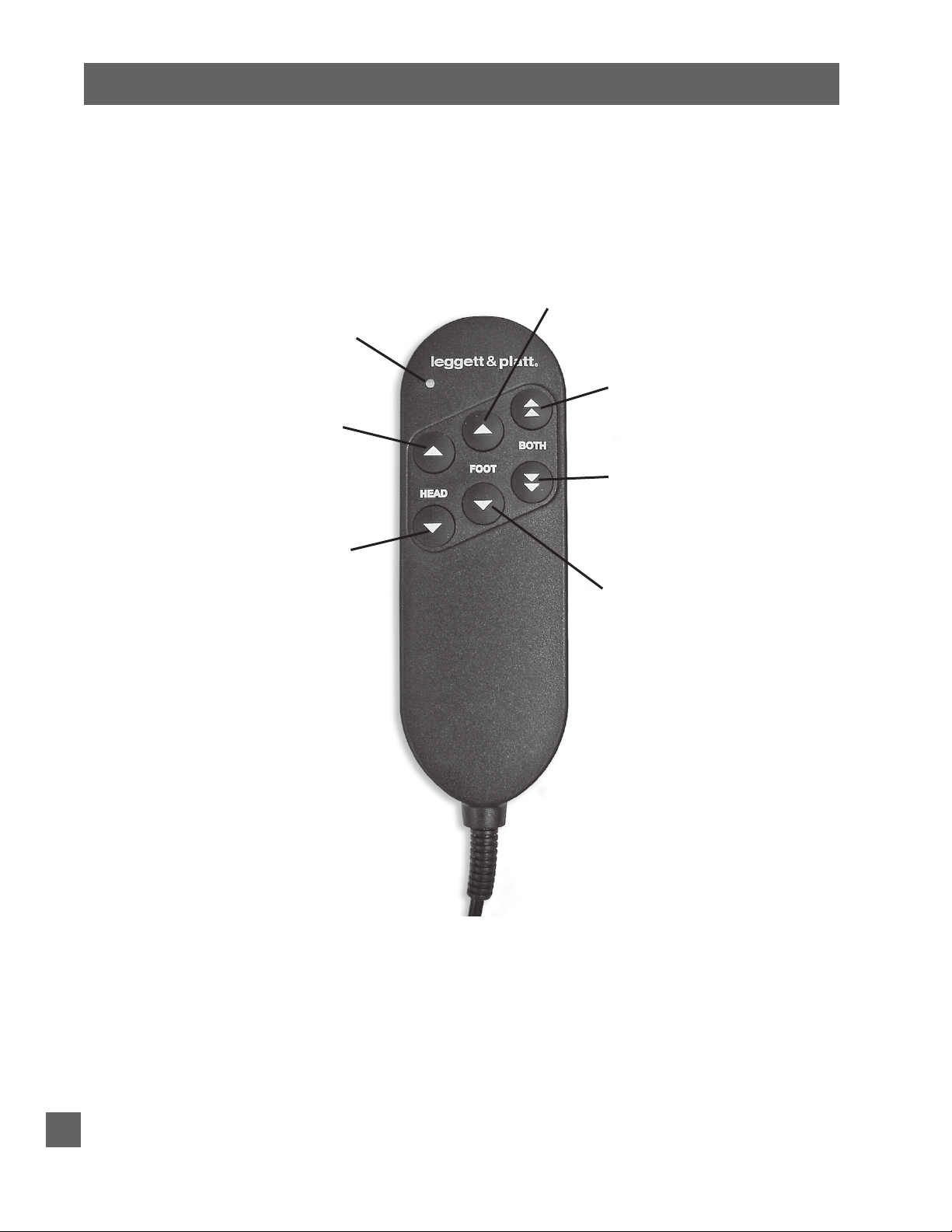
TRANSMISSION INDICATOR LIGHT
Verifies a button is being pressed
and data is being sent to the base.
HEAD UP BUTTON
Press and hold to raise the
head section.
REMOTE CONTROL FUNCTION
FOOT UP BUTTON
Press and hold to raise the
foot section.
HEAD/FOOT UP BUTTON
Press and hold to raise the head
and foot sections simultaneously.
HEAD/FOOT DOWN BUTTON
Press and hold to lower the head
and foot sections simultaneously.
HEAD DOWN BUTTON
Press and hold to lower the
head section.
FOOT DOWN BUTTON
Press and hold to lower the
foot section.
14
Performance Models Pro-motion Owners Manual 99301466-b

TROUBLESHOOTING
In the event the adjustable base fails to operate, investigate the symptoms and possible
solutions provided in the chart below:
SYMPTOM
Remote control will not activate base.
Head or foot section will elevate, but will not
return to the horizontal (flat) position.
SOLUTION
• Verify power cord is plugged into a working, grounded
electrical outlet. A grounded, electrical surge protection
device is recommended. Test outlet by plugging in
another working appliance.
• Verify remote control is plugged into the motor.
• Unplug power cord, wait 30 seconds and plug in to
reset electronic components.
• Electrical circuit breaker may be tripped. Check
electrical service breaker box to verify.
• Defective surge protection device or electrical outlet.
Test outlet by plugging in another working appliance.
• Base mechanism may be obstructed. Elevate base and
check for obstruction. Remove obstruction.
• Head section may be too close to the wall.
• Headboard may be too close the edge of the mattress.
Verify a 1.5” (38.1mm) to 2” (50.8mm) distance
between headboard brackets and mattress. Adjust if
required.
Performance Models Pro-motion Owners Manual 99301466-b
15
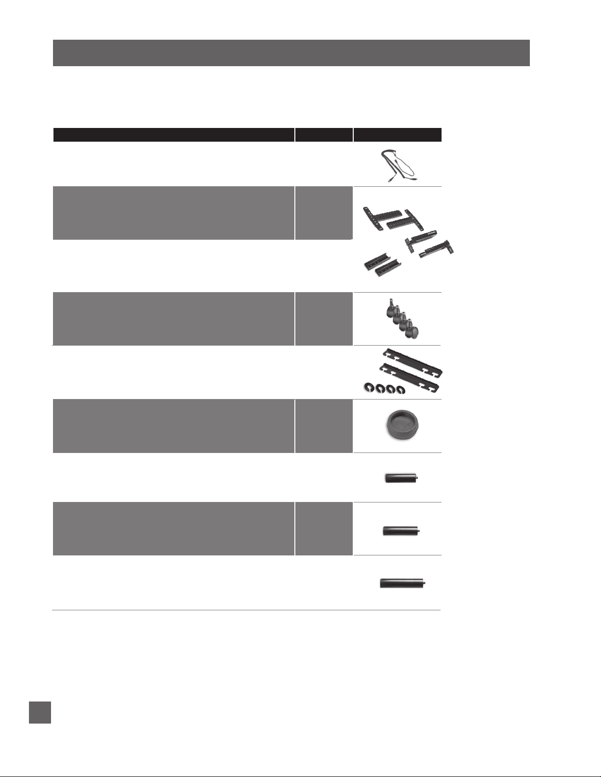
ACCESSORIES
OPTIONAL EQUIPMENT
Contact customer service toll free (800-888-3078) to order the accessories indicated in the chart
below.
ACCESSORY DESCRIPTION
Wired Remote Control Cable - Dual DC Motor
Head Board Brackets-TXL
Head Board Brackets-FXL/Q
Push-in Locking Casters (set of 4)
Bed Link Kit (connects two bases together)
CODE IMAGE
4B5431
4B6117
4B6118
4B1806
4B7410
Rubber Caster Cups (set of 4)
4” Legs (set of 4)
5” Legs (set fo 4)
7” Legs (set of 4)
4B1034
4B1833
4B2100
4B2101
16
Performance Models Pro-motion Owners Manual 99301466-b
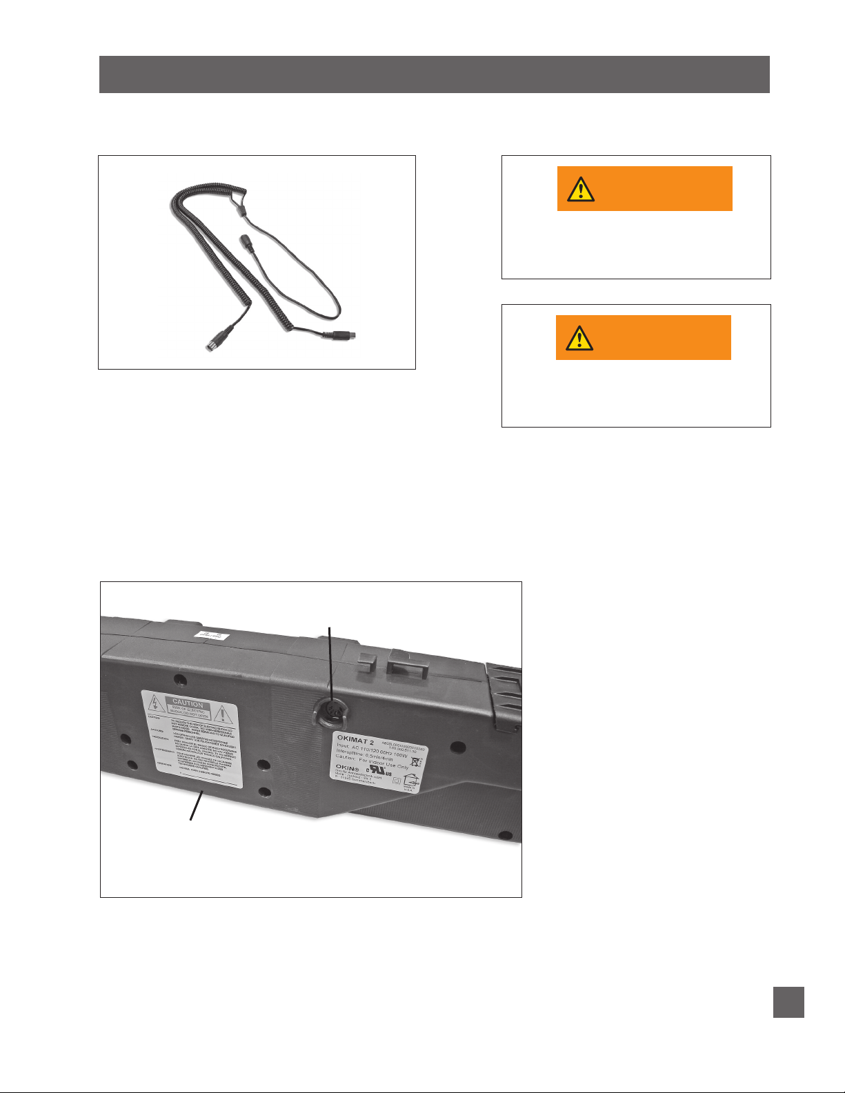
DUAL DC CONNECTOR CABLE (optional accessory)
WARNINGWARNING
WARNINGWARNING
Install dual DC connector cable (FIGURE 1) as follows:
FIGURE 1
BEFORE BEGINNING PROCEDURE,
UNPLUG BASE FROM ELECTRICAL
STEP 1
Unplug bases from electrical power source.
STEP 2
Remove mattresses and mattress retainers from bases. Turn bases
over so they are top-side-down.
RECOMMENDED FOR HANDLING AND
POWER SOURCE.
AT LEAST TWO PEOPLE ARE
MOVING ADJUSTABLE BASE.
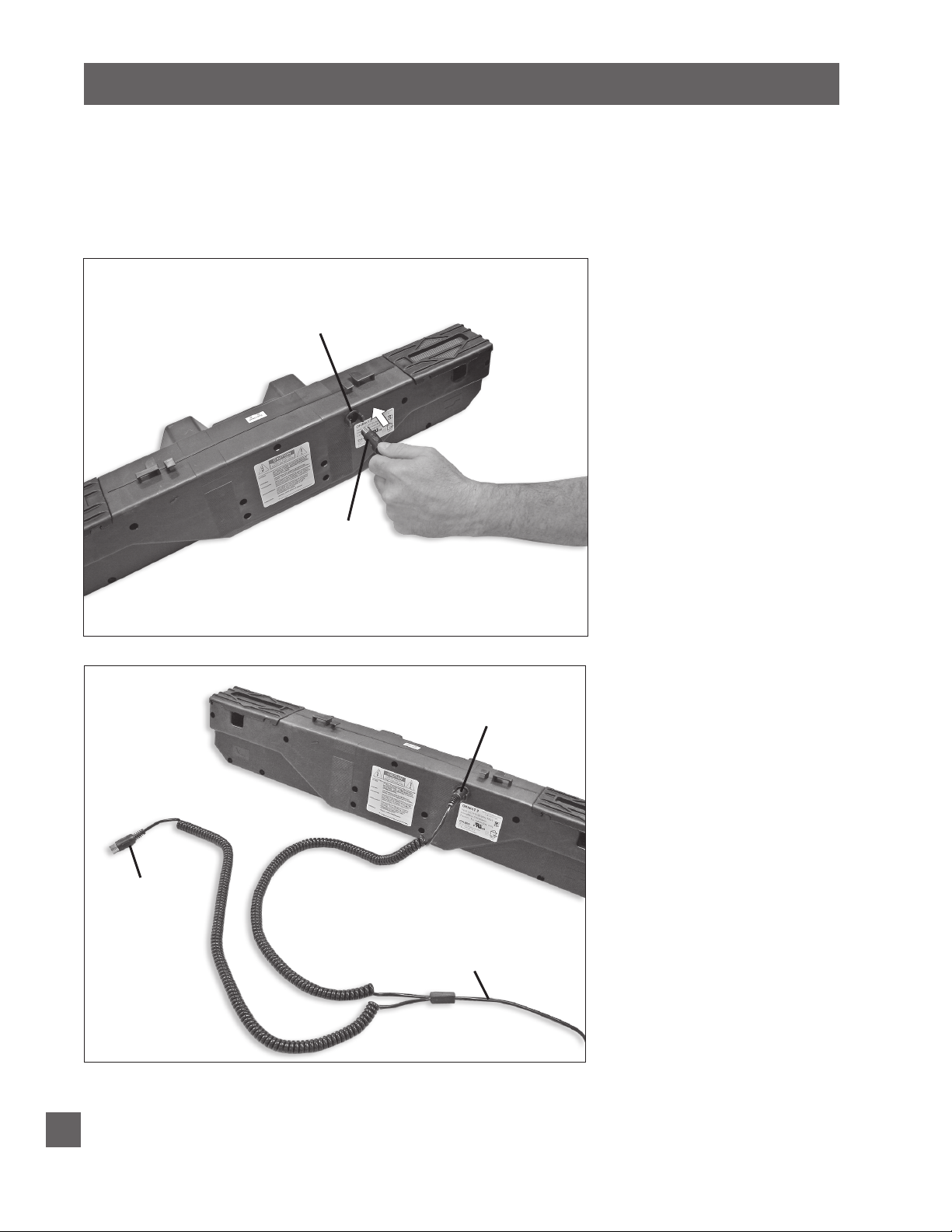
STEP 3
On one (1) base, remove wired remote control plug from insertion
receptacle on motor (FIGURE 2). Retain remote control.
FIGURE 2
DC MOTOR
INSERTION RECEPTACLE
(on motor)
Performance Models Pro-motion Owners Manual 99301466-b
17
DUAL DC CONNECTOR CABLE (optional accessory)
STEP 4
Plug one (1) of the dual DC connector cable plugs into the insertion
receptacle on the motor (FIGURES 3 and 4). Note: Insert carefully.
Line up pins in plug with holes in insertion receptacle. Push in as
far as plug will go.
FIGURE 3
FIGURE 4
INSERTION RECEPTACLE
(on motor)
DUAL DC
CONNECTOR
PLUG
INSTALLED DUAL DC
CONNECTOR PLUG
18
DUAL DC
CONNECTOR
PLUG (for
second base)
Performance Models Pro-motion Owners Manual 99301466-b
DUAL DC
CONNECTOR
CABLE

DUAL DC CONNECTOR CABLE (optional accessory)
STEP 5
Repeat Steps 3 and 4 to install dual DC connector cable plug in
second motor (FIGURE 4). Retain remote control for future use.
Second remote control not required to operate base.
STEP 6
Insert one (1) DC wired remote control plug into dual DC connector
cord receptacle (FIGURES 5 and 6). Note: Line up pins in plug
with holes in receptacle.
FIGURE 5
FIGURE 6
DC WIRED
REMOTE
CONTROL
PLUG
FROM DC
MOTORS
DUAL DC
CONNECTOR
CORD
RECEPTACLE
DUAL DC
CONNECTOR
CORD
RECEPTACLE
DC WIRED
REMOTE
CONTROL
DC WIRED REMOTE
CONTROL PLUG
(90˚CONNECTION)
Performance Models Pro-motion Owners Manual 99301466-b
19

DUAL DC CONNECTOR CABLE (optional accessory)
STEP 7
Carefully turn both bases over so they are right-side-up. Caution:
Make sure cables and cords do not obstruct moving base
components.
STEP 8
Plug one (1) base into electrical power source.
STEP 9
Operate the remote control to verify both adjustable bases operate
simultaneously.
STEP 10
Reinstall mattress retainers and mattresses.
Installation is complete.
20
Performance Models Pro-motion Owners Manual 99301466-b
 Loading...