

Leggett & Platt S-cape+ 2.0, Simplicity 3.0, G-122, G-122 USB, G-122 NWH Owner's Manual
owners manual
G-122 NWH
G-122
G-122 USB
S-cape
®
Simplicity
2.0 / S-cape®+ 2.0 /
™
3.0
ENGLISH
SPANISH
FRENCH
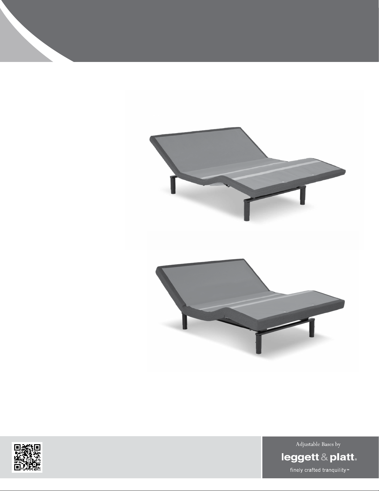
Simplicity
S-cape® 2.0 / S-cape®+ 2.0
™
3.0
LPAdjustableBases.com

CONTENTS
Advisory ...................................................................................................................... 3
Installation ................................................................................................................. 5
Remote Control Function .............................................................................................. 9
Remote Control Programming ..................................................................................... 10
Power Down Operation ............................................................................................... 13
Troubleshooting ......................................................................................................... 16
Accessories ............................................................................................................... 17
Warranty ................................................................................................................... 18
Spanish translation begins on page 20.
La traducción en español inicia en la página 20.
French Canadian translation begins on page 38.
La traduction en Français débute à la page 38.
If adjustable base does not operate or if parts are missing, call:
1.800.888.3078

ADVISORY
important information
READ THE FOLLOWING INFORMATION CAREFULLY BEFORE USING THIS PRODUCT
READ ALL INSTRUCTIONS BEFORE USING
FOR OPTIMUM ADJUSTABLE BASE
OPERATION, USE A GROUNDED, ELECTRICAL
SURGE PROTECTION DEVICE (NOT
INCLUDED). FAILURE TO USE A SURGE
PROTECTION DEVICE COULD COMPROMISE
SAFETY OR CAUSE PRODUCT MALFUNCTION.
ELECTRICAL RATING
Input: 100-240VAC, 50/60Hz, 1.6A. Output:
29VDC, 2A.
ELECTRICAL GROUNDING
This product is equipped with a polarized or
grounded electrical power cord. The power cord will
only fit into a grounded, electrical surge protection
device (not included) or a grounded electrical outlet.
WARRANTY WARNING
Do not open any control boxes, motors or remote
control devices (with the exception of the remote
control and power down box battery compartments).
The product warranty will be void if these
components are tampered with. Do not attempt
to alter component wiring or adjust or modify the
structure of the product in any way or the warranty
will be void. Any repair or replacement of base parts
must be performed by authorized personnel.
LUBRICATION
This product is designed to be maintenance free.
The lift motors are permanently lubricated and
sealed—no additional lubrication is required. Do not
apply lubricant to lift motor lead screws or any nylon
nuts or the base may inadvertently creep downward
from the elevated position.
PRODUCT RATINGS
The base lift motors are not designed for continuous
use. Reliable operation and full life expectancy will
be realized as long as the lift motors do not operate
any more than two (2) minutes over a twenty (20)
minute period, or approximately 10% duty cycle.
Note: Massage equipped bases are not designed for
continuous, extended massage operation. Massage
systems are rated for a maximum of 2 hours of
use within any 6 hour period. Any attempt to
circumvent or exceed product ratings will shorten
the life expectancy of the product and may void the
warranty.
The recommended weight restrictions for these
adjustable bases is 850 lb (385 kg) all sizes. The
base will structurally support the recommended
weight distributed evenly across the head and foot
sections. This product is not designed to support or
lift this amount in the head or foot sections alone.
Depending on the size and/or model of mattress,
the available weight capacity may be less. Note:
Exceeding the recommended weight restrictions
could damage the mattress and void the warranty.
For best performance, consumers should enter and
exit the adjustable base with the base in the flat
(horizontal) position.
FOOT SECTIONS WHILE IN THE RAISED POSITION.
Motors and electronics have been ETL tested to UL
(Underwriters Laboratories) standard UL962.
CFR 1633 approved for use with most mattresses.
Assembled in USA.
MASSAGE OPERATION
The massage feature will emit a minimal tone
during operation. This is normal. When the massage
level is increased, motor resonance will intensify
accordingly.
DO NOT SIT ON THE HEAD OR
S-cape® 2.0 / S-cape®+ 2.0 / Simplicity™ 3.0 Owners Manual 290-0010-c
3

ADVISORY
important information
READ THE FOLLOWING INFORMATION CAREFULLY BEFORE USING THIS PRODUCT
SMALL CHILDREN / PETS WARNING
After the base is unboxed, immediately dispose of
packaging material as it can smother small children
and pets. To avoid injury, children or pets should not
be allowed to play under or on the base. Children
should not operate this base without adult supervision.
PACEMAKER WARNING
This product produces a vibrating sensation.
It is possible that individuals with heart-assist
pacemakers may experience a sensation similar to
exercise. Consult physician for complete information.
HOSPITAL USE DISCLAIMER
This base is designed for in-home use only. It
is not approved for hospital use and does not
comply with hospital standards. Do not use this
base with tent type oxygen therapy equipment,
or use near explosive gases. Manufacturer makes
no representation or warranty that the adjustable
base constitutes a medical device or is suitable for
medical or therapeutic use.
SERVICE REQUIREMENTS
Service technicians are not responsible for moving
furniture, removing headboards and footboards
or any items required to perform maintenance on
the base. In the event the technician is unable to
perform service due to lack of accessibility, the
service call will be billed to the purchaser and the
service will have to be rescheduled.
LIFTING/LOWERING MECHANISMS
The lift/lower feature will emit a minimal humming
sound during operation. This is normal.
During operation, the lift arm wheels make contact
with the platform support of the base. This
applies slight tension on the moving components
and resonance is reduced to a minimum level. If
excessive noise or vibration is experienced, reverse
the movement action (up or down) of the base with
the remote control. This should realign the base’s
activating mechanisms to the proper operational
position.
FCC COMPLIANCE
The equipment has been tested and found to
comply with the limits for a Class B digital device,
pursuant to Part 15 of the FCC Rules. These limits
are designed to provide reasonable protection
against harmful interference when the equipment
is operated in a residential environment. This
equipment generates, uses, and can radiate radio
frequency energy and, if not installed and used in
accordance with the instruction manual, may cause
harmful interference to radio communications.
However, there is no guarantee that interference
will not occur in a particular installation. If this
equipment does cause harmful interference to radio
or television reception, which can be determined
by turning off the equipment off and on, the user is
encouraged to try to correct the interference by one
or more of the following measures:
- Reorient or relocate the receiving antenna
- Increase the separation between the
equipment and receiver.
- Connect the equipment into an outlet on a
circuit different from that to which the
receiver is connected.
- Consult the dealer or an experienced radio/TV
technician for help.
Radio Frequency = 433MHz.
LOCATION ENVIRONMENT
The level of sound experienced during operation
is directly related to the location environment. For
example, when a base is located on a hardwood floor
with the massage feature in operation, a vibrating
tone will be audible.
S-cape® 2.0 / S-cape®+ 2.0 / Simplicity™ 3.0 Owners Manual 290-0010-c
4
INSTALLATION
For installation and setup, complete the numbered procedure indicated below and on the
following pages:
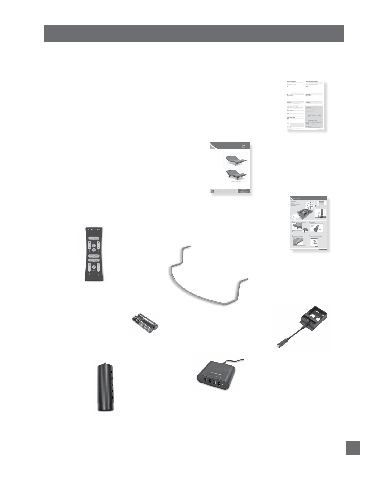
STEP 1
Before discarding any packing materials,
check the base shipping carton and verify the
following items are included:
• (1) Mattress Retainer
• (4) Bed Legs
• (1) Remote Control
• (2) AAA Batteries
• (1) 4-Port Charging Hub
(S-cape®+ 2.0 only)
• (1) Power Down Device (batteries not included)
• (1) Owners Manual
• (1) Warranty Activation Card
• (1) Quick Setup Guide
OWNERS MANUAL
WARRANTY
ACTIVATION CARD
REMOTE CONTROL
LEG
(4 pieces)
QUICK SETUP GUIDE
MATTRESS
RETAINER
2-AAA BATTERIES
POWER DOWN DEVICE
(2) 9 volt batteries not included
4-PORT CHARGING HUB -
S-cape®+ 2.0 only
Factory attached to base.
Split Queen bases will have
free-standing USB option.
S-cape® 2.0 / S-cape®+ 2.0 / Simplicity™ 3.0 Owners Manual 290-0010-c
5
INSTALLATION
WARNINGWARNING
WARNINGWARNING
STEP 2
Uncoil the main power cord and extend it out head
end of base, then remove the hardware box from
shipping container. Cut the zip-tie and remove the
mattress retainer.
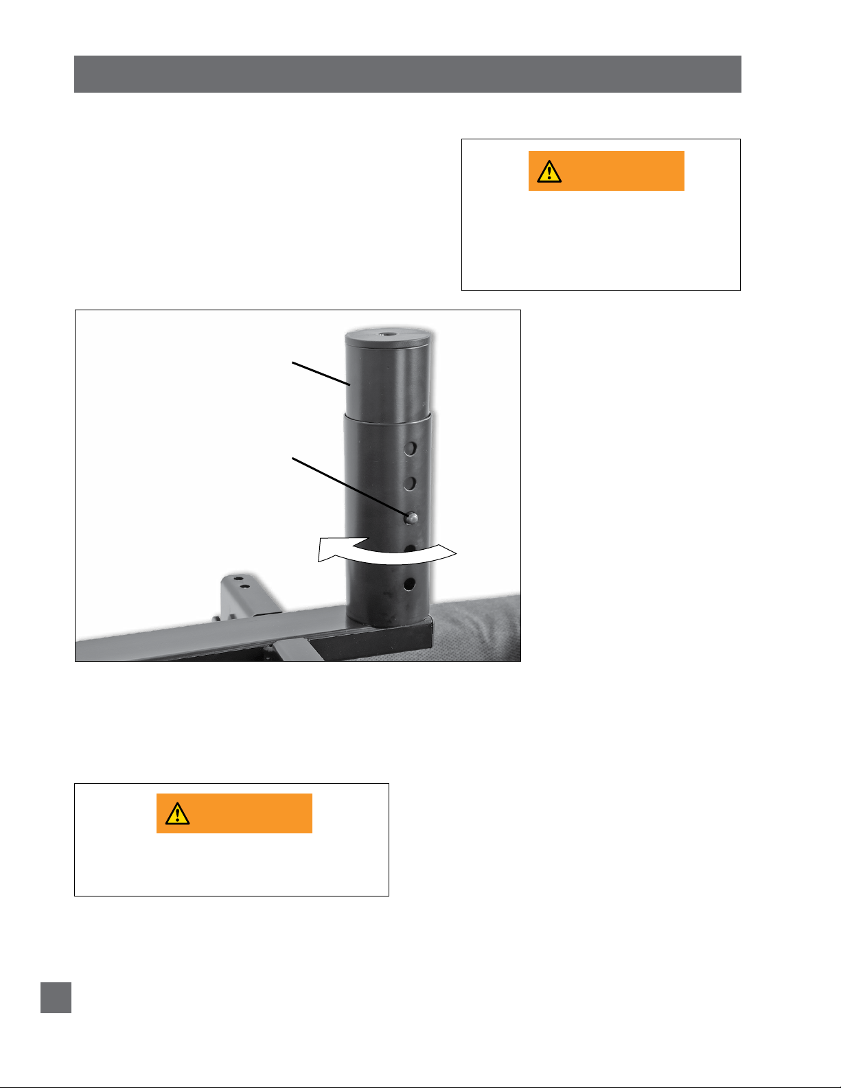
STEP 3
Install (4) legs into the base frame. Simply screw each
leg into a tapped hole at each corner of the base frame
(FIGURE 1).
FIGURE 1
LEGS – SCREW INTO
TAPPED HOLE AT
EACH CORNER
PUSH PIN IN
TO ADJUST LEG
HEIGHT
(6 INCHES TO
10 INCHES)
READ ALL INSTRUCTIONS BEFORE USING
POWER CORDS MUST NOT INTERFERE
WITH ANY ADJUSTABLE BASE
MECHANISMS.
DO NOT WEAVE CORDS THROUGH BASE
STRUCTURE.
STEP 4
With base still in shipping carton, rotate the entire bottom carton on
its edge and then gently rotate over so base is resting on its legs.
READ ALL INSTRUCTIONS BEFORE USING
DUE TO RISK OF INJURY, TWO PEOPLE
ARE REQUIRED TO HANDLE AND MOVE
S-cape® 2.0 / S-cape®+ 2.0 / Simplicity™ 3.0 Owners Manual 290-0010-c
6
ADJUSTABLE BASE.
INSTALLATION
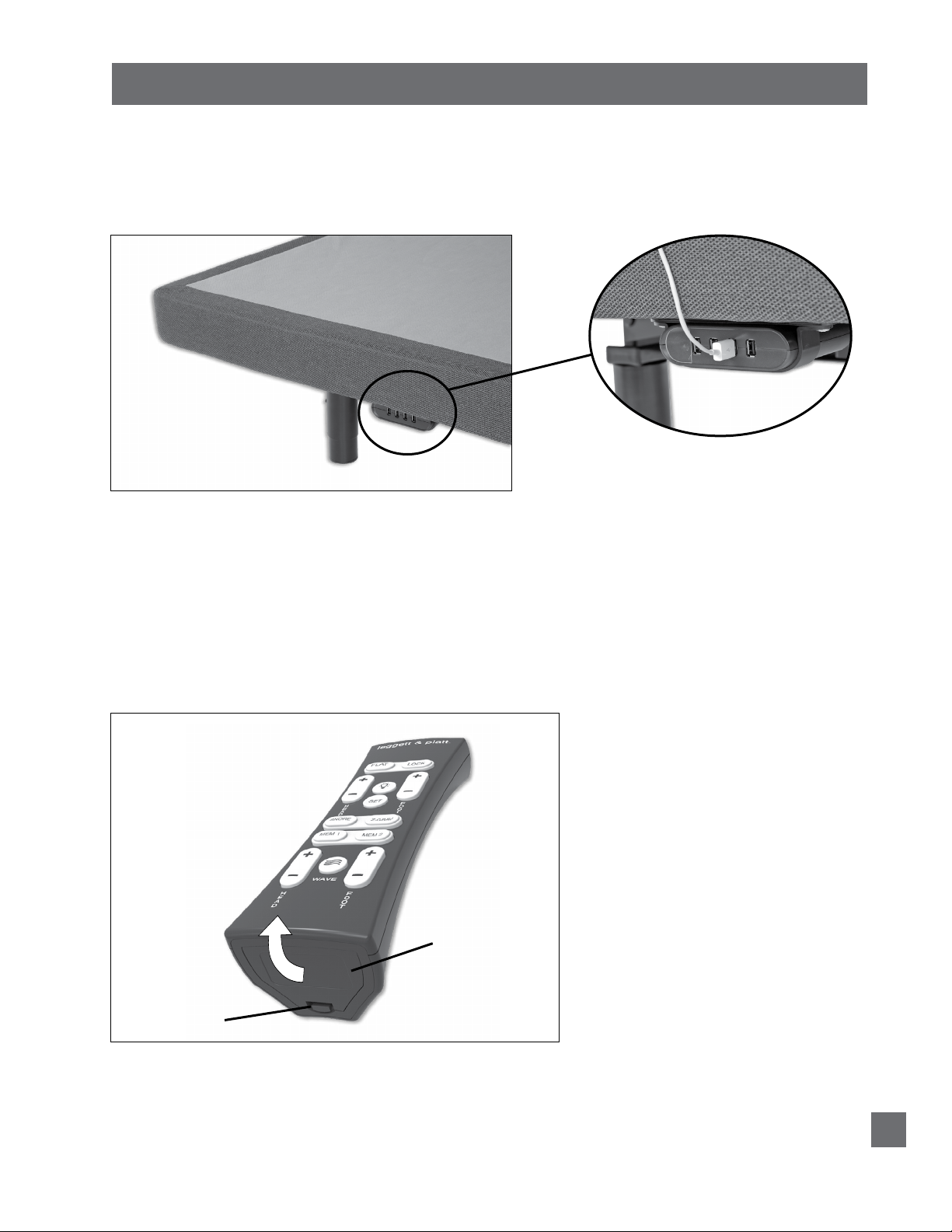
STEP 5
Remove the shipping carton and plastic packaging from the adjustable base frame.
Remove protective film from Micro-Hook™ strips, if applicable. Note: S-cape
base includes a 4-port charging hub at head end of base (FIGURE 2).
FIGURE 2
HEAD END OF BASE
4-PORT CHARGING HUB
(S-cape®+ 2.0 base only)
(located on each side of
base, for charging lowvoltage devices only; hub is
free-standing on Split Queen
bases)
STEP 6
Plug electrical power cord into a working, grounded electrical outlet.
Note: an electrical surge protection device is recommended (not included).
®
+ 2.0
STEP 7
Install batteries in remote control (2-AAA size, included) (FIGURE 3).
Briefly activate all functions of the base with the remote control to verify
all features are in working order. If base does not operate, refer to the
Troubleshooting section of this manual.
FIGURE 3
DISENGAGE LATCH ON
BATTERY COMPARTMENT
DOOR AND LIFT UP TO
REMOVE. INSERT TABS IN
TAB SLOTS AND SNAP LATCH
IN TO REPLACE.
BATTERY
COMPARTMENT
DOOR
DOOR
LATCH
STEP 8
Return base to the level position.
S-cape® 2.0 / S-cape®+ 2.0 / Simplicity™ 3.0 Owners Manual 290-0010-c
7
INSTALLATION
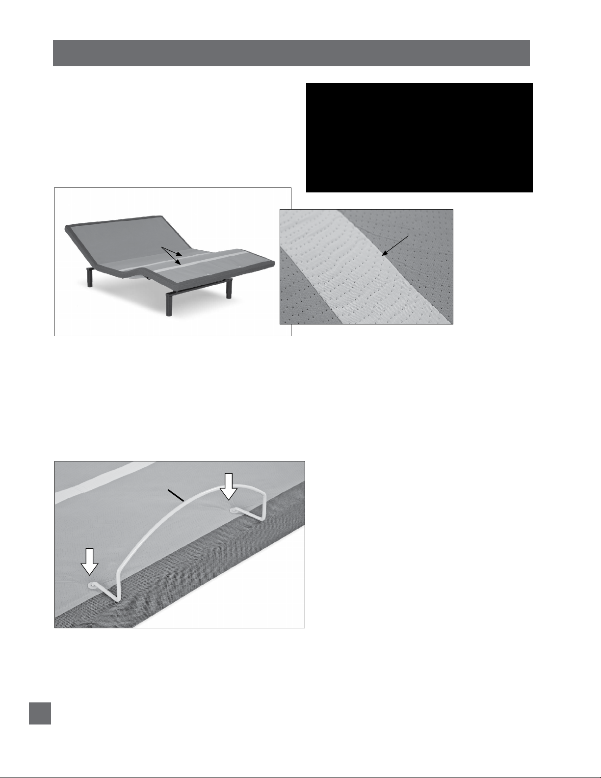
MATTRESS RETAINER INSTALLATION (OPTIONAL)
Mattress is equipped with a Micro-Hook™ system
to captivate the mattress (FIGURE 4), but if
desired a mattress retainer can also be used. If
installing a mattress retainer, proceed to Step 9.
If not installing a mattress retainer, proceed to
Step 10.
FIGURE 4
IMPORTANT!
THIS PRODUCT SHOULD NOT BE USED WITH
EITHER A DUST RUFFLE OR A MATTRESS
ENCASEMENT. IF EITHER A DUST RUFFLE
OR MATTRESS ENCASEMENT IS NEEDED,
THEN A MATTRESS RETAINER BAR IS
REQUIRED.
Micro-Hook™
SYSTEM
Simplicity™ 3.0
BASE SHOWN
(articulated)
STEP 9
Install mattress retainers at the foot end of the adjustable base as
follows:
a. Locate grommeted holes at foot of base (FIGURE 5).
b. Place mattress retainer ends into grommeted holes in top
surface of adjustable base (FIGURE 5). Press down until
horizontal retainer section is flush against base.
FIGURE 5
MATTRESS
RETAINER
Micro-Hook™
DETAIL
STEP 10
Install mattress on adjustable base.
Typical adjustable base installation is now complete.
S-cape® 2.0 / S-cape®+ 2.0 / Simplicity™ 3.0 Owners Manual 290-0010-c
8
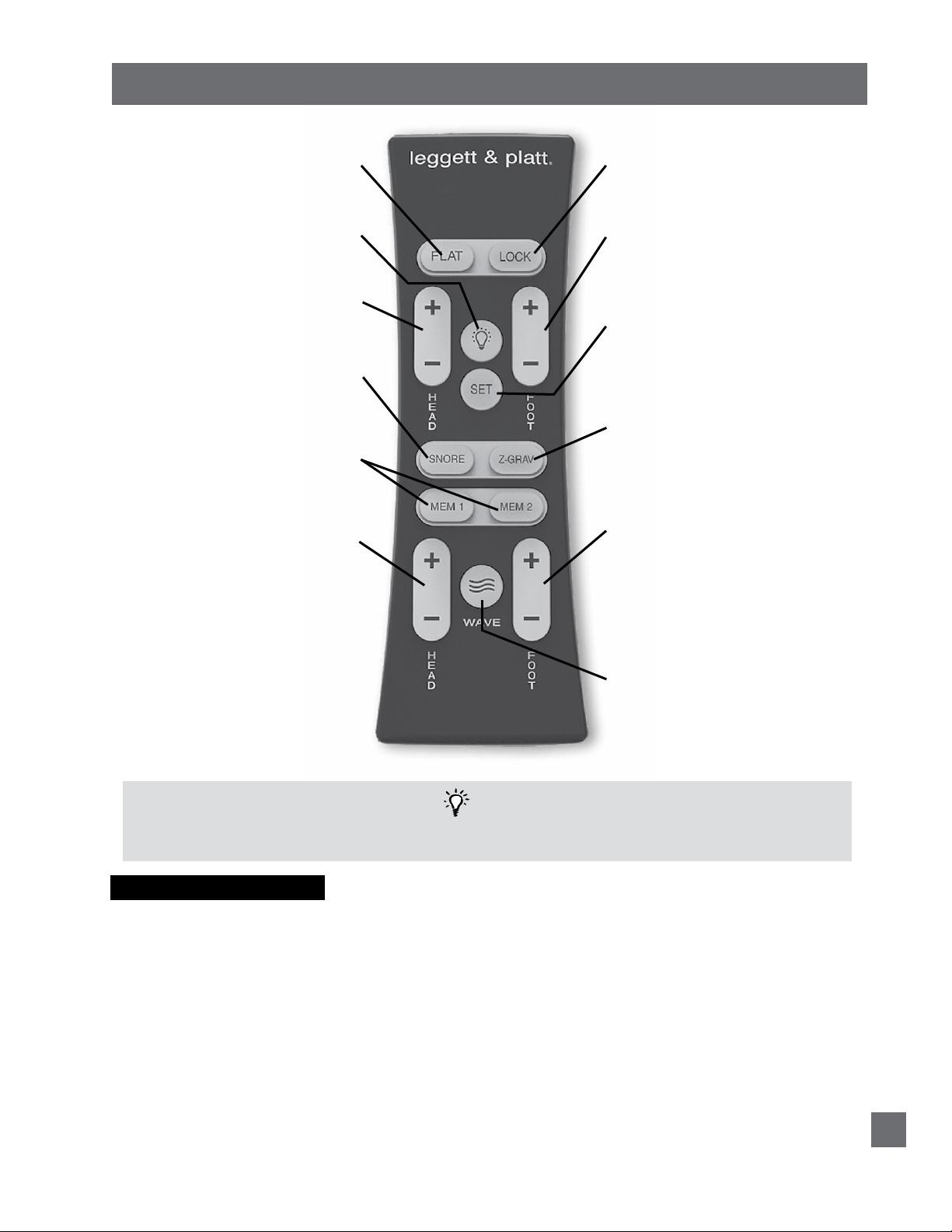
REMOTE CONTROL FUNCTION
FLAT BUTTON
Press and hold to lower the base to the
flat position. This button will also turn
off the massage motors and underbed
light.
UNDERBED LIGHT BUTTON
Press to turn on/off underbed light
feature.
HEAD UP/DOWN BUTTONS
Press and hold to raise or lower the
head section.
SNORE BUTTON
Press and hold to adjust the head
section of the base to a 7° angle. The
section will return to the flat position
after 15 minutes.
MEM 1 / MEM 2 BUTTONS
Press and hold to adjust the base to the
programmed position.
HEAD MASSAGE UP/DOWN BUTTONS
Press and release to increase/decrease
head massage intensity. Massage has
3 levels: Low, medium and high. Press
the down button when massage in set
to low intensity to turn massage off.
Massage will automatically shut off after
30 minutes.
LOCK BUTTON
To lock / unlock the remote control
buttons, press and hold lock button for
3 seconds. Backlight will flash 3 times.
FOOT UP/DOWN BUTTONS
Press and hold to raise or lower the foot
section.
SET BUTTON
To program a position, adjust base to
desired position and/or function, then press
and hold the set button AND Mem 1, Mem
2, Snore, or Z Grav. The massage motors
will “chirp” once to confirm success.
ZERO GRAVITY BUTTON
Press and hold to adjust the base to the
preprogrammed reclined position for
optimum weight distribution allowing
total comfort and relaxation.
FOOT MASSAGE UP/DOWN BUTTONS
Press and release to increase/decrease
foot massage intensity. Massage has 3
levels: Low, medium and high. Press
the down button when massage in set
to low intensity to turn massage off.
Massage will automatically shut off after
30 minutes.
WAVE INTENSITY BUTTON
Press and release to turn on wave feature.
Press wave button again to turn off wave
feature and return massage to non-wave
massage. After wave is activated, press
and hold the button for 3 seconds to cycle
through the wave speeds. To adjust wave
intensity, press head/foot (+) or (-) buttons.
NOTE
REMOTE CONTROL REQUIRES THREE (2) AAA SIZE BATTERIES. TO CONSERVE BATTERY LIFE, THE
TRANSMITTER TURNS OFF ALL FUNCTIONS WHEN ANY BUTTON IS PRESSED FOR MORE THAN 50 SECONDS.
PRESS & HOLD TO ONE TOUCH
To change remote control functions from “press and hold” to “one touch” (“one touch” = press and release), simultaneously press
the FLAT and HEAD UP buttons for 3 seconds. The massage motors will chirp once confirming the change. Your base is now set to
“one touch.”
When in “one touch” (press and release) mode:
• Mem 1, Mem 2, Z Grav and Snore buttons
Press and release (one touch) button. Base will adjust to the programmed position. Press any other button to stop the base during movement.
• Flat button
Press and release (one touch) button. Base will shut off massage motor, if active, and adjust base to level position. Press any other
button to stop the base during movement.
To revert back to factory settings, simultaneously press and hold the FLAT button and the HEAD DOWN button for 3 seconds. The
massage motors will chirp once confirming the change. Your base is now set to factory settings. Note: Mem 1, Mem 2, Z Grav and
Snore positions will revert to factory preprogrammed positions.
S-cape® 2.0 / S-cape®+ 2.0 / Simplicity™ 3.0 Owners Manual 290-0010-c
9
REMOTE CONTROL PROGRAMMING
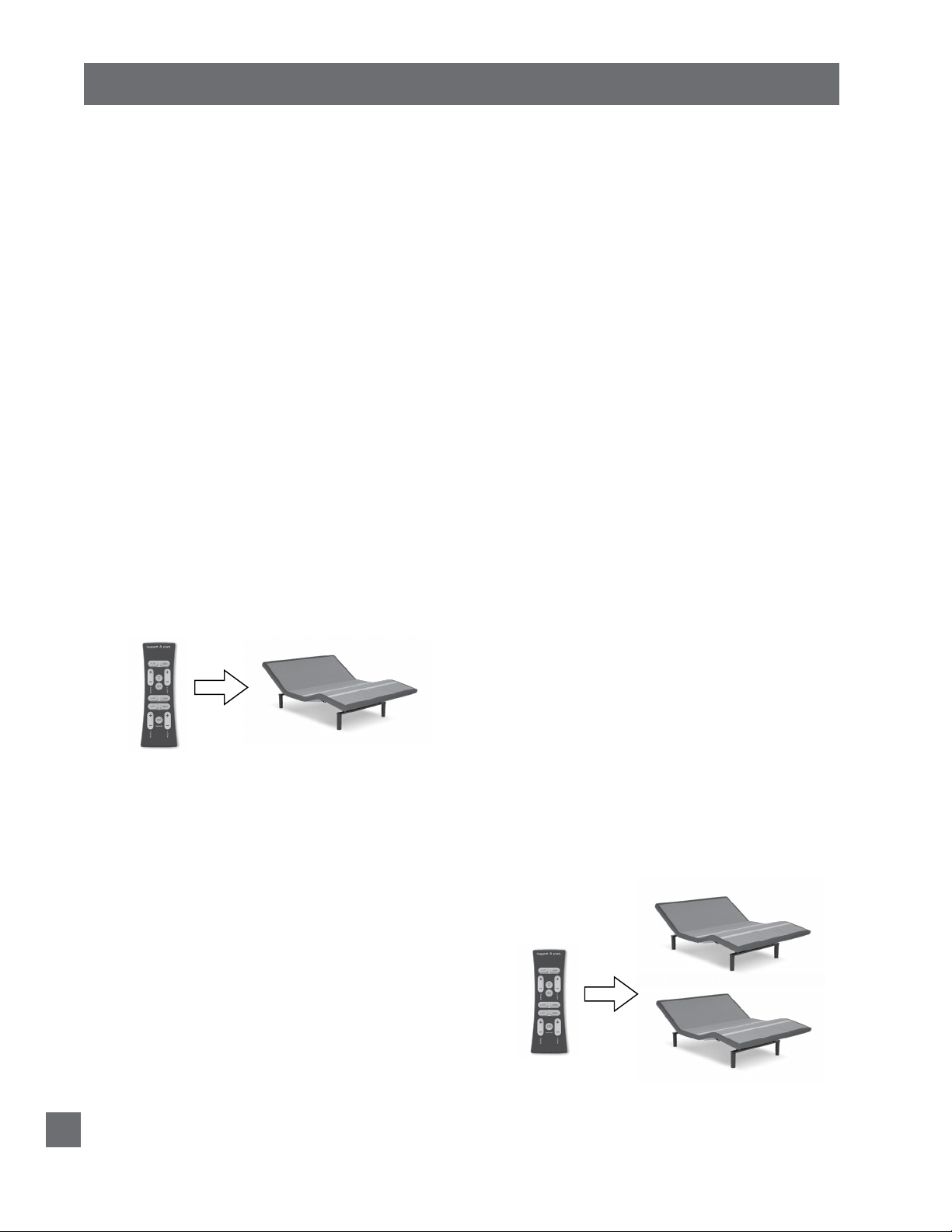
Program One Remote to Operate One Base - Bases
are factory programmed to operate as one remote
control to one base. If reprogramming is required,
perform the following numbered procedure. If
programming fails, initiate the programming
procedure a second time.
STEP 1
UNPLUG the base from the electriclal power source
(if plugged in). Wait 3 minutes.
STEP 2
Plug the base into the electrical power source.
You now have 3 minutes to complete the
programming procedure.
STEP 3
Simultaneously press and hold the head up and foot
up buttons on the remote control until the backlight
flashes. Release both buttons.
Press the head up or foot up button on the remote
control to verify base functions.
One remote control is now programmed to operate
one base.
Program One Remote to Operate Two Bases - Bases
are factory programmed to operate individual
bases. To program one remote to operate both
bases, perform the following numbered procedure.
If programming fails, initiate the programming
procedure a second time.
STEP 1
UNPLUG both bases from the electriclal power
source (if plugged in). Wait 3 minutes.
STEP 2
Plug base 1 into the electrical power source.
You now have 3 minutes to complete the
programming procedure.
STEP 3
Simultaneously press and hold the head up and foot
up buttons on the remote control until the backlight
flashes. Release both buttons.
STEP 4
Plug base 2 into the electrical power source.
You now have 3 minutes to complete the
programming procedure.
STEP 5
Simultaneously press and hold the head up and foot
up buttons on the remote control until the backlight
flashes. Release both buttons.
Press the head up or foot up button on the remote
control to verify both bases function.
One remote control is now programmed to operate
two bases.
Note: The second remote is not needed. Store it for
use as a spare.
BASE 1
BASE 2
S-cape® 2.0 / S-cape®+ 2.0 / Simplicity™ 3.0 Owners Manual 290-0010-c
10
REMOTE CONTROL PROGRAMMING
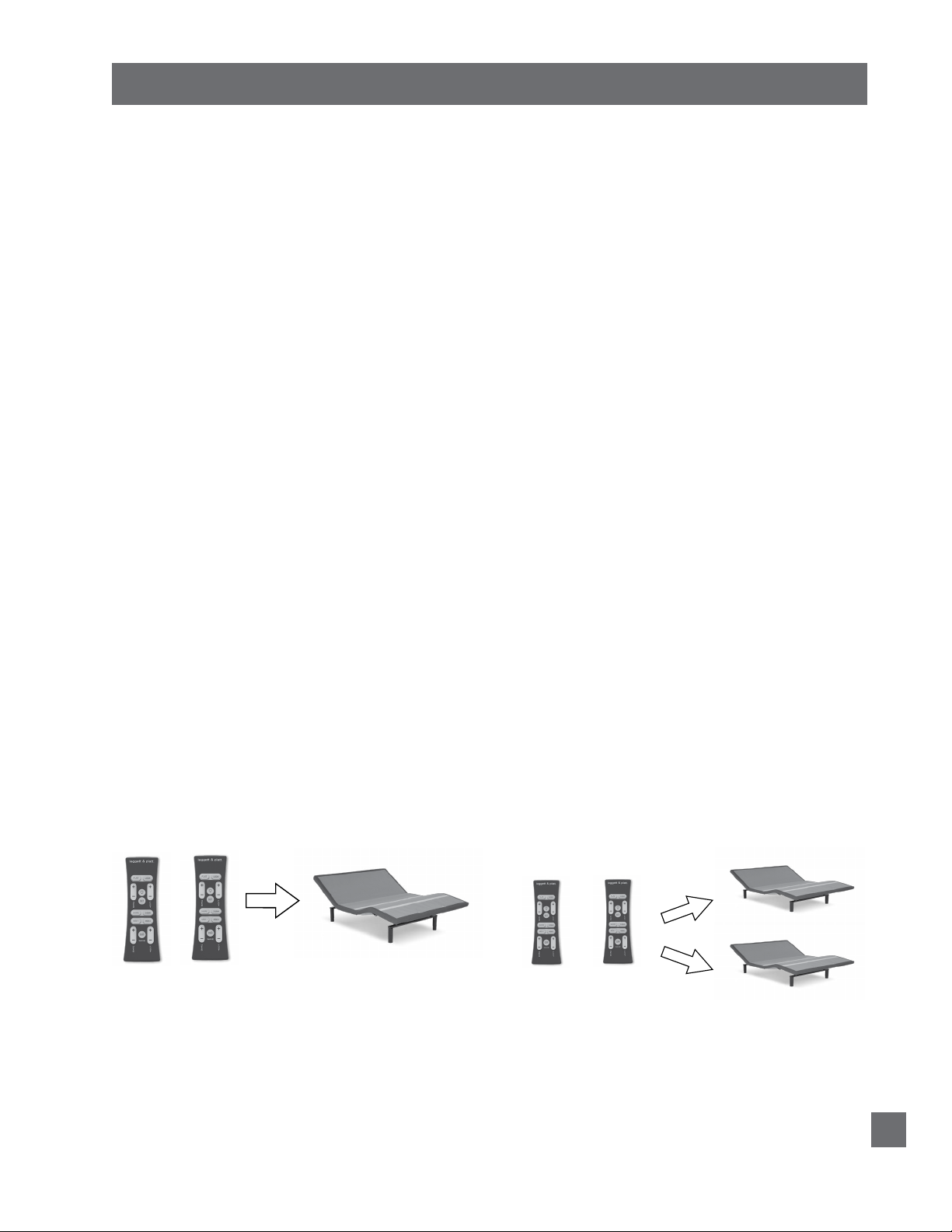
Program Two Remotes to Operate One Base - Bases
are factory programmed to operate individual
bases. To program two remotes to operate one
base, perform the following numbered procedure.
If programming fails, initiate the programming
procedure a second time.
STEP 1
UNPLUG the base from the electriclal power source
(if plugged in). Wait 3 minutes.
STEP 2
Plug the base into the electrical power source.
You now have 3 minutes to complete the
programming procedure.
STEP 3
Simultaneously press and hold the head up and foot
up buttons on remote control 1 until the backlight
flashes. Release both buttons and set remote control
1 aside without pressing any other button.
NOTE: If any button is pressed, remote control/
control box will exit pairing mode.
Program Two Remotes to Operate Two Bases -
Bases are factory programmed to operate individual
bases. To program two remotes to operate two
bases, perform the following numbered procedure.
If programming fails, initiate the programming
procedure a second time.
STEP 1
UNPLUG both bases from the electrical power
source (if plugged in). Wait 3 minutes.
STEP 2
Plug both bases into the electrical power source.
You now have 3 minutes to complete the
programming procedure.
STEP 3
Simultaneously press and hold the head up and foot
up buttons on remote control 1 until the backlight
flashes. Release both buttons and set remote control
1 aside without pressing any other button.
NOTE: If any button is pressed, remote control/
control box will exit pairing mode.
STEP 4
Simultaneously press and hold the head up and foot
up buttons on remote control 2 until the backlight
flashes. Release both buttons.
Press the head up or foot up button on remote
control 2 to verify base functions.
Press the head up or foot up button on remote
control 1 to verify base functions.
Two remote controls are now programmed to operate
one base.
REMOTE
CONTROL 1
REMOTE
CONTROL 2
STEP 4
Simultaneously press and hold the head up and foot
up buttons on remote control 2 until the backlight
flashes. Release both buttons.
Press the head up or foot up button on remote
control 2 to verify base functions.
Press the head up or foot up button on remote
control 1 to verify base functions.
Two remote controls are now programmed to operate
two bases.
BASE 1
REMOTE
CONTROL 1
REMOTE
CONTROL 2
BASE 2
S-cape® 2.0 / S-cape®+ 2.0 / Simplicity™ 3.0 Owners Manual 290-0010-c
11

REMOTE CONTROL PROGRAMMING
Reprogram Two Remote Controls for Individual
Base Operation - Bases are factory programmed
to operate individual bases. To reprogram bases
synced to multiple remote controls, perform the
following numbered procedure. Individual base
operation will result. If programming fails, initiate
the programming procedure a second time.
STEP 1
UNPLUG both bases from the electriclal power
source (if plugged in). Wait 3 minutes.
STEP 2
Plug base 1 into the electrical power source.
You now have 3 minutes to complete the
programming procedure.
STEP 3
Simultaneously press and hold the head up and foot
up buttons on remote control 1 until the backlight
flashes. Release both buttons.
BASE 1
REMOTE CONTROL 1
BASE 2
REMOTE CONTROL 2
Press the head up or foot up button on remote
control 1 to verify base functions and exit pairing
mode.
STEP 4
Plug base 2 into the electrical power source.
STEP 5
Simultaneously press and hold the head up and foot
up buttons on remote control 2 until the backlight
flashes. Release both buttons.
Press the head up or foot up button on remote
control 2 to verify base functions.
Independent operation is now restored. Remote control
1 operates base 1; remote control 2 operates base 2.
S-cape® 2.0 / S-cape®+ 2.0 / Simplicity™ 3.0 Owners Manual 290-0010-c
12
POWER DOWN OPERATION
To lower base to the flat position during an electrical power outage,
complete the following procedure:
NOTE
FOR EMERGENCY USE ONLY. BATTERIES
ARE NOT TO BE USED FOR NORMAL
OPERATION OF BASE (9-VOLT ALKALINE
BATTERIES NOT INCLUDED)
STEP 1
Verify power supply is unplugged from electrical power source.
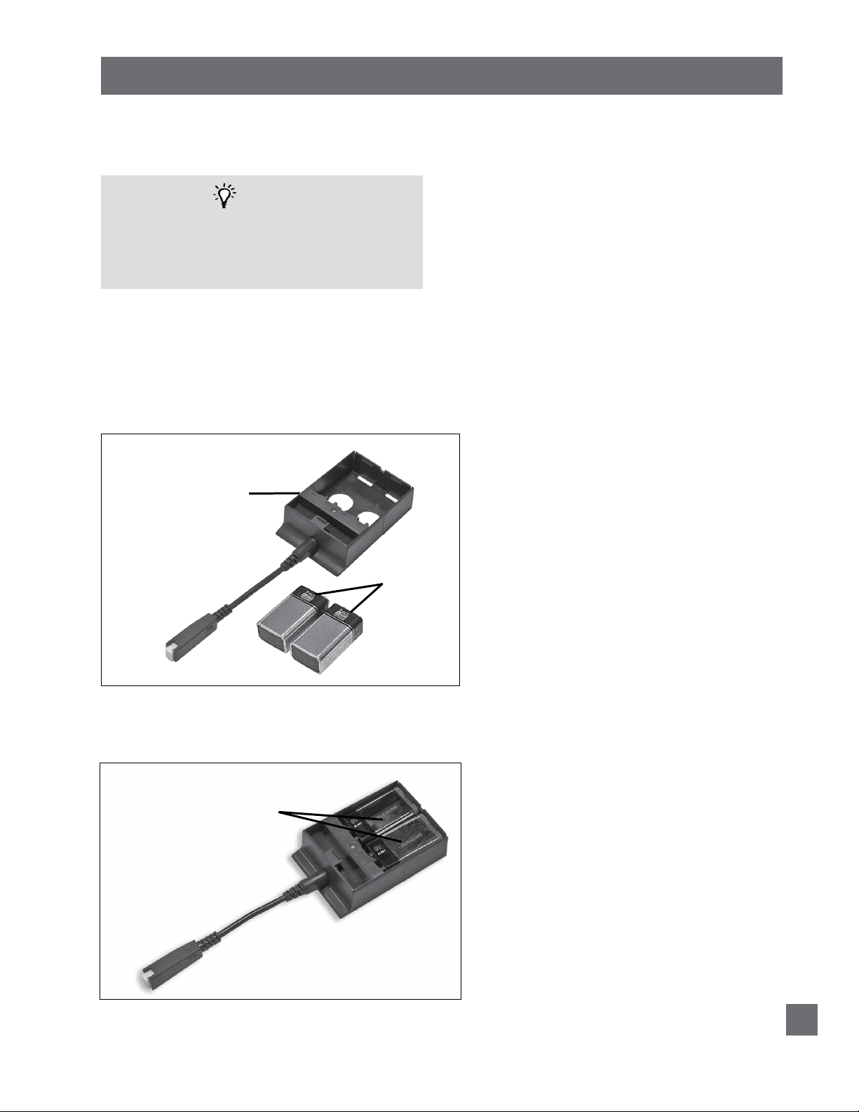
STEP 2
Locate (1) power down device and two (2) 9-volt alkaline batteries (not included)
(FIGURE 6).
FIGURE 6
(1) POWER
DOWN
DEVICE
(2) 9-VOLT
ALKALINE
BATTERIES
(NOT
INCLUDED)
STEP 3
Install (2) 9-volt alkaline batteries in power down device (FIGURE 7).
FIGURE 7
ALKALINE
BATTERIES
INSTALL ONLY
ONE WAY IN
POWER DOWN
DEVICE
S-cape® 2.0 / S-cape®+ 2.0 / Simplicity™ 3.0 Owners Manual 290-0010-c
13
POWER DOWN OPERATION
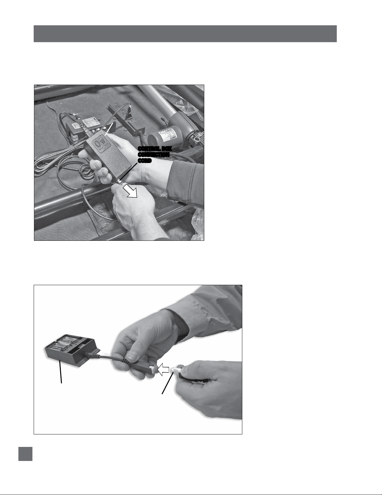
STEP 4
Push tab in on control box connection cord and pull out to remove
control box connection cord from power supply “brick” (FIGURE 8).
FIGURE 8
POWER
SUPPLY
“BRICK”
CONTROL BOX
CONNECTION
CORD
STEP 5
Connect control box connection cord to power down device (FIGURES 9
and 10).
FIGURE 9
POWER
DOWN
DEVICE
CONTROL BOX
CONNECTION
CORD (removed
from power supply
“brick”)
S-cape® 2.0 / S-cape®+ 2.0 / Simplicity™ 3.0 Owners Manual 290-0010-c
14
POWER DOWN OPERATION
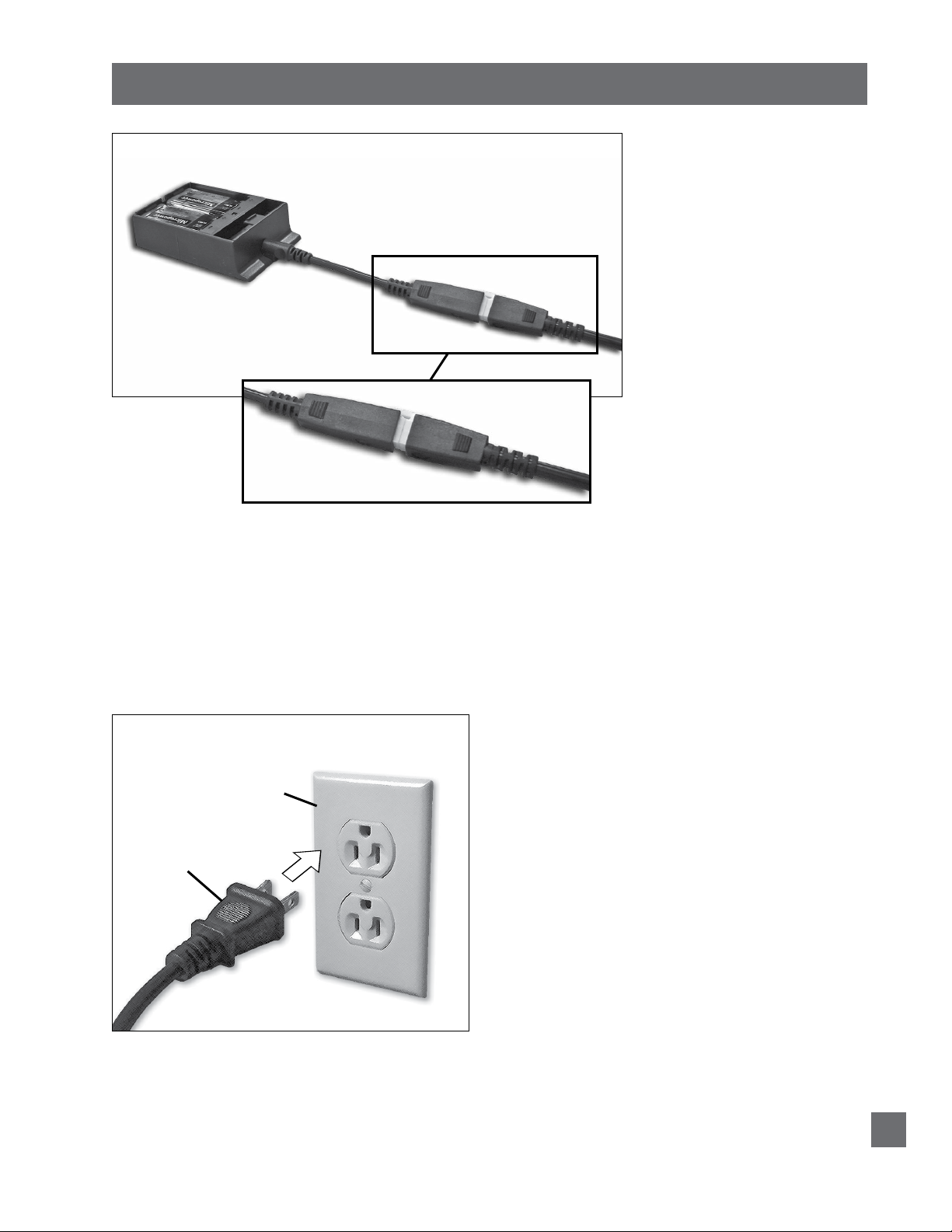
FIGURE 10
CONTROL BOX
CONNECTION CORD
CONNECTED TO
POWER DOWN DEVICE
STEP 6
Press the FLAT BUTTON on the remote control until the base is in
the flat position. BASE WILL MOVE TO THE FLAT POSITION VERY
SLOWLY. Note: Batteries in the power down device will only work for
one use, then will need to be replaced.
STEP 7
Reconnect control box connection cord to power supply “brick” and
plug main power cord into electrical power source (FIGURE 11).
FIGURE 11
ELECTRICAL
POWER
SOURCE
MAIN
POWER
CORD
When power is restored from outage, base is ready to resume normal operation.
S-cape® 2.0 / S-cape®+ 2.0 / Simplicity™ 3.0 Owners Manual 290-0010-c
15

TROUBLESHOOTING
If the adjustable base fails to operate, investigate the symptoms and possible solutions
provided in the chart below:
SYMPTOM
Remote control illuminates and appears to be
operable, but will not activate base.
No features of the base will activate.
Remote control will not illuminate.
Head or foot section will elevate, but will not
return to the horizontal (flat) position.
SOLUTION
• Verify power cord is plugged into a working, grounded
electrical outlet. A grounded, electrical surge protection
device is recommended. Test outlet by plugging in
another working appliance.
• If the base was operated over the rated duty cycle,
thermal switch opens. Wait 30 minutes before trying
to operate the base. Once the base resumes normal
operation, do not exceed the duty cycle.
• Program the remote control (see Remote Control
Programming section of this manual for programming
procedures).
• Unplug power cord, wait 30 seconds and plug in to
reset electronic components.
• Electrical circuit breaker may be tripped. Check
electrical service breaker box to verify.
• Defective surge protection device or electrical outlet.
Test outlet by plugging in another working appliance.
• Replace batteries in the remote control.
• Base mechanism may be obstructed. Elevate base and
check for obstruction. Remove obstruction.
• Head section may be too close to the wall.
• Headboard (if used) may be too close the edge of the
mattress. Verify a 1.5” (38.1mm) to 2” (50.8mm)
distance between headboard brackets and mattress.
Adjust if required.
Excessive massage motor noise.
S-cape® 2.0 / S-cape®+ 2.0 / Simplicity™ 3.0 Owners Manual 290-0010-c
16
• If base is located on hard surface ooring, place carpet
pieces or rubber caster cups under each leg or caster
of the base. (See accessory section of this manual for
rubber caster cup order information.)
• Elevate the head or foot section a short distance (with
the remote control) to realign the lift/lower mechanisms
with the base support platform.
• Verify that the base is not positioned against a wall,
nightstand, or other object that may cause vibration or
noise.
• If base is installed over a bed frame, verify massage
motors are not causing bed frame (or bed frame
components) to vibrate.
• Verify that headboard attachment hardware is tightened
firmly (if used).
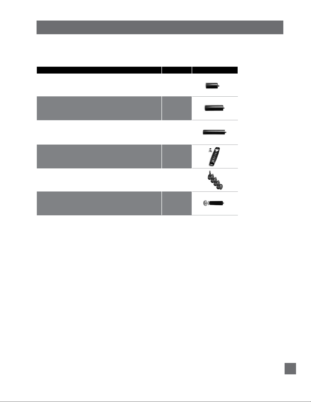
ACCESSORIES
OPTIONAL EQUIPMENT
Contact customer service toll free (800-888-3078) to order the accessories indicated in the chart
below.
ACCESSORY DESCRIPTION
3” Legs
4” Legs (set of 4)
5” Legs (set of 4)
Swing-away Hinges
Push-in Locking Casters (set of 4)
5” Adjustable Leg Kit2 (adjustment range: 6-1/8” to 9-3/8”)
(set of 4)
1
CODE IMAGE
4B2284
4B1833
4B2100
4B1209
4B0107
4B3402
1
Swing-away hinges are designed for use with dual queen or dual king size bed bases. The swing-away hinge allows easy access
between two mated bases for domestic cleaning (i.e. sweeping, changing sheets) by swinging the beds apart.
2
Leg kit contains 6 adjustable legs and pre-cut foam rubber stripping for use with center support system.
S-cape® 2.0 / S-cape®+ 2.0 / Simplicity™ 3.0 Owners Manual 290-0010-c
17
 Loading...