

Page 1
Lead Free Water Pressure Reducing Valves (PRV)
Models T-6800NL, T-6801NL, T-6802NL and T-6803NL Installation Instructions
Application:
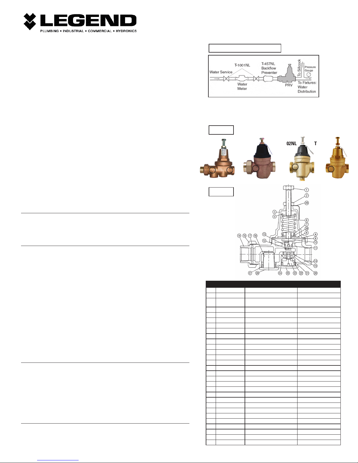
Typically installed between the water main and a building’s water distribution system, on the water service line,
to reduce and maintain incoming water pressure (see Fig. 1). All models are suitable for no-lead potable water
installations, in full compliance of all lead-free plumbing laws.
Installation Requirements:
1. MUST be installed in accordance with all local codes and ordinances.
2. MUST be installed in an accessible location on the service line, with sufcient clearance for maintenance and
adjustment.
3. Models with brass bonnets are designed for outdoor use. Models with reinforced plastic bonnets should not be
installed outdoors where prolonged exposure to sunlight and temperature extremes could result in damage.
4. Prior to installation, the service line MUST be ushed, to remove all loose scale, dirt, debris or other foreign
matter. Failure to do so could result in damage or clogging of the valve.
Basic Installation:
1. Connection types vary between each model and may include FNPT, Sweat, PEX, CPVC solvent-weld or Pressconnection types. Where applicable, the installation tool manufacturers’ instructions should be followed. In
all other cases, good industry practice should be followed (e.g. proper thread engagement and tightening, or
correct soldering technique).
2. The T-6800NL model’s end connections are marked “IN” and “OUT”. All models have a ow direction arrow
cast onto their bodies. Make sure to install them with the arrow pointing in the direction of ow (see Fig. 2).
Valve inlet (“IN”): Upstream, high-pressure service line. Valve outlet (“OUT”): Downstream, reduced-pressure
distribution system.
3. All models can be installed in the vertical or horizontal positions, upright or inverted. When installed
horizontally, it is recommended that they’re oriented upright, positioning the adjustment bolt upward, which
eases servicing and adjustment.
4. When placing into service, apply water pressure gradually. Check for leaks at all connections.
Maintenance Instructions:
Inspect the entire system annually. Make sure all safety and control valves are functioning correctly and that the
entire system is leak-free.
See Figures 3 and 4 for numbered component identication, for the following maintenance procedures:
To clean the inlet strainer screen (18):
Model T-6800NL
A. Shut off water supply and relieve system pressure.
B. Loosen and remove the strainer service cap (28) by turning counter-clockwise.
C. Remove and clean or replace the mesh strainer screen (18)
D. Re-install the mesh strainer, making sure it is seated properly.
E. Inspect the strainer cap O-ring (27) for damage. Replace if necessary. Re-install the strainer cap.
Models T-6801NL, T-6802NL and T-6803NL
A. Shut off water supply and relieve system pressure.
B. Loosen locknut (2) rst, and then adjustment bolt (1) by turning both counter-clockwise at least two complete
revolutions.
C. Loosen and detach the bonnet (3) by un-threading it counter-clockwise.
D. Remove the following components that are contained within the bonnet: anti-friction ring (4), spring disc (5)
and spring (6).
E. With a pair of pliers, grip the 13 MM diaphragm nut, from the top, using the tips of the pliers’ jaws (don’t
grip the nut’s ats from the side, as if loosening the nut).
F. Firmly pull out the entire carrier assembly from the body of the valve. The carrier assembly is comprised of parts
7, 8, 9, 10, 11, 12, 13, 18 (strainer screen) 19, 20, 21, 22, 24, 25 and 26 assembled as one piece. See Figure 4.
G. Remove and clean or replace the mesh strainer screen (18)
H. Re-install the clean mesh strainer into the body (14) making sure it is centrally-seated into the machined
pocket.
I. Inspect the upper sleeve O-ring (27) verifying that it is free of debris or damage and properly seated within the
body (14).
J. Re-install the carrier assembly into the body (14). Make sure to seat it in completely, by rmly pushing down
onto the top of the stem with your thumb.
K. Once seated, with your ngertips, work the outer edges of the diaphragm (9) into the body until its entire
circumference is evenly-seated. CAUTION! The female threads that accept the male threads of the bonnet (3)
are sharp! Be careful not to cut your ngers when pushing the diaphragm down. DO NOT use tools or sharp
objects to seat the diaphragm! Remaining assembly is in the reverse-order.
To replace the plunger seat (T-6800NL: 22, T-6801NL, T-6802NL & T-6803NL 21):
Model T-6800NL
A. Shut off water supply and relieve system pressure.
B. Loosen locknut (2) rst, and then adjustment bolt (1) by turning both counter-clockwise at least two complete
revolutions.
C. Loosen and detach the bonnet (3) by un-threading it counter-clockwise.
D. Remove the following components that are contained within the bonnet: anti-friction ring (4), spring disc (5)
and spring (6).
E. Loosen and remove the service cap (25) by turning counter-clockwise.
F. Hold the diaphragm nut (7) with a 17 MM wrench. With a large at-blade screwdriver, loosen counter-clockwise
and detach the plunger (23) from the stem (10).
G. Remove the plunger washer (21) and plunger seat (22) by separating them from the plunger. Replace with the
correct seat material and size. Re-assembly is in the reverse-order.
Models T-6801NL, T-6802NL and T-6803NL
A. Shut off water supply and relieve system pressure.
B. Loosen locknut (2) rst, and then adjustment bolt (1) by turning both counter-clockwise at least two complete
revolutions.
Continued on the reverse page
Figure 1 (Typical Installation)
WARNING:
Conduct a thorough inspection of the PRV for external leaks after the
nal installation and adjustment.
Figure 2
T-6800NL T-6801NL
T-6802NL
T-6803NL
Figure 3
T-6800NL
Cut-away
No. Part Material Specification
1 Adjustment bolt Cadmium Plated Steel ASTM A283-D
2 Lock Nut Cadmium Plated Steel AISI-1010
3 Bonnet Cast brass or Polycarbonate resin, glass-ber
4 Anti-friction ring Zinc Plated Steel ASTM A283-D
5 Spring disc Zinc Plated Steel ASTM A283-D
6 Spring Cold Drawn Steel Wire ASTM A227M-91
7 Diaphragm nut Cadmium Plated Steel AISI-1010
8 Diaphragm disc Zinc Plated Steel ASTM A283-D
9 Diaphragm Reinforced NBR (Buna-N) Rubber Commercial grade, Nylon-reinforced
10 Stem Lead-Free Forged Brass UNS Alloy C46400
11 Check ball NBR (Buna-N) Rubber Commercial grade
12 Ball retaining screw Stainless Steel AISI 304
13 Stem O-ring NBR (Buna-N) Rubber Commercial grade
14 Body Lead-Free Cast Brass UNS Alloy C87850 Eco Brass
15 Union nut Cast Brass ASTM B584 UNS C85700
16 Union tail piece Lead-Free Forged Brass UNS Alloy C46400
17 Union washer NBR (Buna-N) Rubber Commercial grade
18 Strainer screen Stainless Steel AISI 304
19 Seat O-ring NBR (Buna-N) Rubber Commercial grade
20 Seat Stainless Steel AISI 304
21 Plunger washer Stainless Steel AISI 304
22 Plunger seat NBR (Buna-N) Rubber Commercial grade
23 Plunger Lead-Free Forged Brass UNS Alloy C46400
24 Service cap O-ring NBR (Buna-N) Rubber Commercial grade
25 Service cap Lead-Free Forged Brass UNS Alloy C46400
26 Name plate Aluminum ASTM B209 1100
27 Strainer cap O-ring NBR (Buna-N) Rubber Commercial grade
28 Strainer service cap Lead-Free Forged Brass UNS Alloy C46400
29 Spring washer Cold Drawn Steel ASTM A227M-91
reinforced
ASTM B584 UNS C85700
(brass) Commercial grade (resin)
Rev. 12.15
Page 2
Lead Free Water Pressure Reducing Valves (PRV)
Models T-6800NL, T-6801NL, T-6802NL and T-6803NL Installation Instructions
C. Loosen and detach the bonnet (3) by un-threading it counter-clockwise.
D. Remove the following components that are contained within the bonnet: anti-friction ring (4), spring disc (5)
and spring (6).
E. With a pair of pliers, grip the diaphragm nut (7), from the top, using the tips of the pliers’ jaws (don’t
grip the nut’s ats from the side, as if loosening the nut).
F. Firmly pull out the entire carrier assembly from the body of the valve. The carrier assembly is comprised of
parts 7, 8, 9, 10, 11, 12, 13, 18 (strainer screen) 19, 20, 21, 22, 24, 25 and 26 assembled as one piece. See
Figure 4.
G. Hold the diaphragm nut (7) with a 13 MM wrench. With a large at-blade screwdriver, loosen counter-
clockwise and detach the plunger (22) from the stem (10).
H. Remove the plunger washer (20) and plunger seat (21) by separating them from the plunger. Replace with
the correct seat material and size. Re-assembly is in the reverse-order.
To replace the diaphragm (9):
Model T-6800NL
A. Shut off water supply and relieve system pressure.
B. Loosen locknut (2) rst, and then adjustment bolt (1) by turning both counter-clockwise at least two
complete revolutions.
C. Loosen and detach the bonnet (3) by un-threading it counter-clockwise.
D. Remove the following components that are contained within the bonnet: anti-friction ring (4), spring disc (5)
and spring (6).
E. Loosen and remove the service cap (25) by turning counter-clockwise.
F. Hold the diaphragm nut (7) with a 17 MM wrench. With a large at-blade screwdriver, loosen counter-
clockwise and detach the plunger (23) from the stem (10).
G. Using your index nger, push the bottom of the stem (10, where the plunger was installed) upward to detach
the stem and diaphragm (9) assembly out of the valve’s body.
H. Secure the 22 MM hex-shaped portion of the stem (10) that is directly underneath the diaphragm (9) using
a 22 MM deep-well socket and ratchet or breaker-bar. Prevent the stem from rotating as you loosen counterclockwise, and detach the diaphragm nut (7) using a 17 MM wrench.
I. Remove the spring washer (29), diaphragm disc (8) and diaphragm (9) by lifting them off of the stem.
Replace with the correct diaphragm. Re-assembly is in the reverse-order. Apply one drop of low-strength
thread-locking compound to the male threads of the stem prior to attaching the diaphragm nut.
Models T-6801NL, T-6802NL and T-6803NL
A. Shut off water supply and relieve system pressure.
B. Loosen locknut (2) rst, and then adjustment bolt (1) by turning both counter-clockwise at least two
complete revolutions.
C. Loosen and detach the bonnet (3) by un-threading it counter-clockwise.
D. Remove the following components that are contained within the bonnet: anti-friction ring (4), spring disc (5)
and spring (6).
E. With a pair of pliers, grip the diaphragm nut (7), from the top, using the tips of the pliers’ jaws (don’t
grip the nut’s ats from the side, as if loosening the nut).
F. Firmly pull out the entire carrier assembly from the body of the valve. The carrier assembly is comprised of
parts 7, 8, 9, 10, 11, 12, 13, 18, 19, 20, 21, 22, 24, 25 and 26 assembled as one piece. See Figure 4.
G. Hold the diaphragm nut (7) with a 13 MM wrench. With a large at-blade screwdriver, loosen counter-
clockwise and detach the plunger (22) from the stem (10).
H. With one hand, hold the carrier assembly rmly. With the thumb of the free hand, push the bottom of the
stem (10) and diaphragm (9) out of the carrier sleeve (24)
I. Secure the 18 MM hex-shaped portion of the stem (10) that is directly underneath the diaphragm (9) using an
18 MM deep-well socket and ratchet or breaker-bar. Prevent the stem from rotating as you loosen counterclockwise, and detach the diaphragm nut (7) using a 13 MM wrench.
J. Remove the spring washer (25), diaphragm disc (8) and diaphragm (9) by lifting them off of the stem.
Replace with the correct diaphragm. Re-assembly is in the reverse-order. Apply one drop of low-strength
thread-locking compound to the male threads of the stem prior to attaching the diaphragm nut.
Adjustment:
CAUTION! Post-adjusted pressure MUST be veried! A pressure gauge should be installed downstream to
verify the pressure setting. All models are factory pre-set at 50 psi.
To adjust the pressure:
1. With a 17 MM (13 MM on Models T-6801NL, T-6802NL & T-6803NL) open-end wrench, loosen the locknut
(2) by turning counter-clockwise.
2. With a 17 MM (13 MM on Models T-6801NL, T-6802NL & T-6803NL) wrench or socket, turn the adjustment
bolt (1) CLOCKWISE to INCREASE the outlet pressure or COUNTER-CLOCKWISE to DECREASE outlet
pressure.
3. After adjustment and pressure verication, tighten the locknut by turning clockwise until it is rmly-seated
against the top of the bonnet. DO NOT OVER-TIGHTEN!
Maximum inlet pressure: 300 CWP
Maximum temperature: 180° F
Reduced pressure adjustment range: 25 to 75 psi.
By-pass Feature:
All models feature a built-in thermal expansion by-pass. This feature prevents downstream pressure from
rising to more than 10 psi above the supply pressure.
Troubleshooting - High System Pressure:
WARNING! All plumbing components within the distribution system MUST be protected against excess
pressure, where the addition of a pressure relief valve of the appropriate type, may be required. The installer
is responsible for knowing and complying with all local or National code requirements pertaining to pressure
relief.
If the downstream system pressure is higher than the set pressure under no ow conditions, the cause could
be thermal expansion, pressure creep or dirt/debris on the seat.
Thermal expansion occurs whenever water is heated in a closed system. The system is closed when supply
pressure exceeds 150 psi, or a check valve or backow preventer is installed in the supply piping.
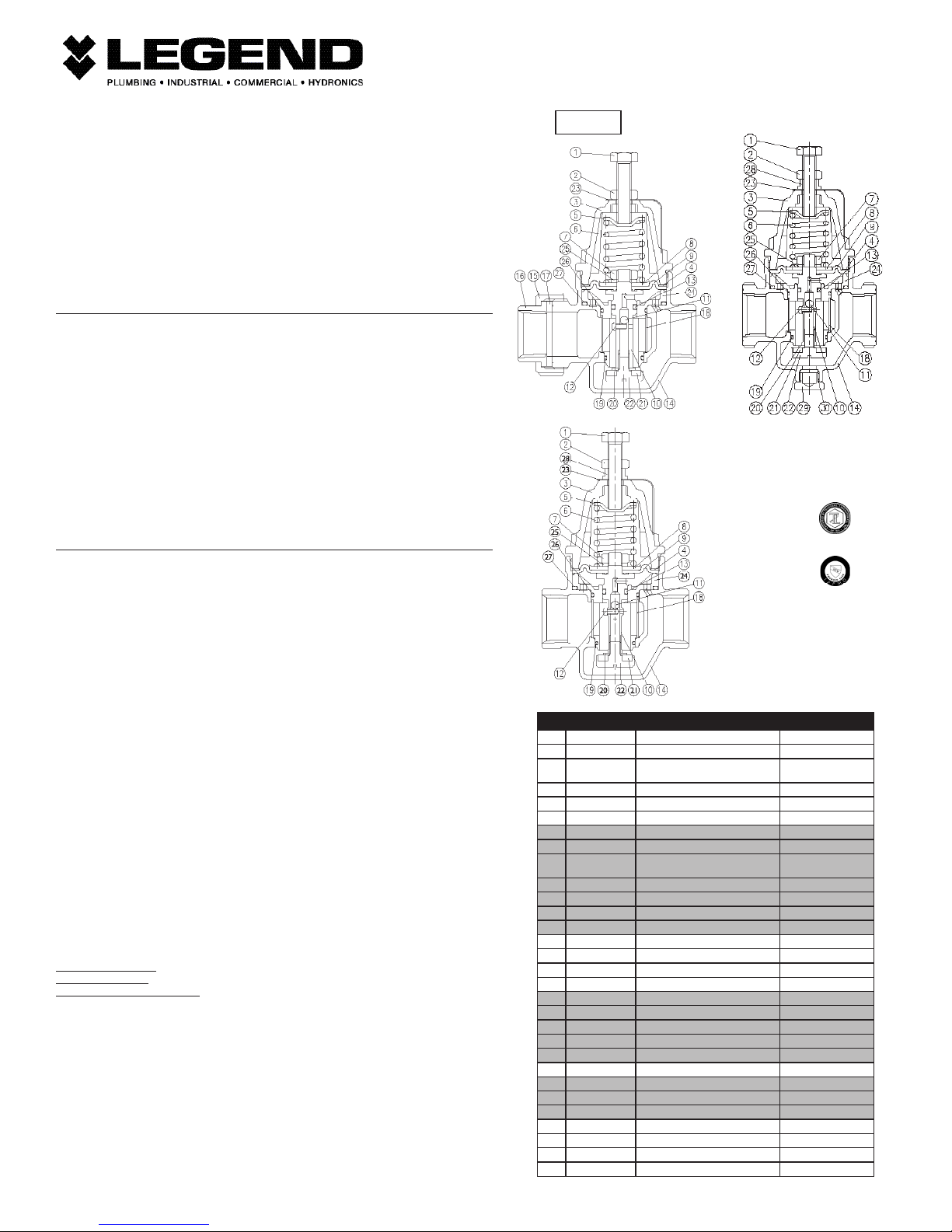
Figure 4
T-6801NL
Cut-away
T-6803NL
Cut-away
ANSI / NSF 61-F and 61-G
ANSI / NSF 372
• Certied to ASSE
1003 Standard
Please contact Legend Technical at 800-752-2082
with additional questions.
No. Part Material Specification
1 Adjustment bolt Cadmium Plated Steel ASTM A283-D
2 Lock Nut Cadmium Plated Steel AISI-1010
3 Bonnet Cast brass or Polycarbonate resin, glass-ber
4 Anti-friction ring Stainless steel AISI 304
5 Spring disc Zinc Plated Steel ASTM A283-D
6 Spring Cold Drawn Steel Wire ASTM A227M-91
7 Diaphragm nut Cadmium Plated Steel AISI-1010
8 Diaphragm disc Zinc Plated Steel ASTM A283-D
9 Diaphragm Reinforced NBR
10 Stem Lead-Free Forged Brass UNS Alloy C46400
11 Check-ball NBR (Buna-N) Rubber Commercial grade
12 Ball retaining screw Stainless Steel AISI 304
13 Stem O-ring NBR (Buna-N) Rubber Commercial grade
14 Body Lead-Free Cast Brass UNS Alloy C87850 Eco Brass
15 Union nut Cast Brass ASTM B584 UNS C85700
16 Union tailpiece Lead-Free Forged Brass UNS Alloy C46400
17 Union washer NBR (Buna-N) Rubber Commercial grade
18 Strainer screen Stainless Steel AISI 304
19 Seat O-ring NBR (Buna-N) Rubber Commercial grade
20 Plunger washer Stainless Steel AISI 304
21 Plunger seat NBR (Buna-N) Rubber Commercial grade
22 Plunger Lead-Free Forged Brass UNS Alloy C46400
23 Identication plate Aluminum ASTM B209 1100
24 Carrier sleeve Polycarbonate resin Commercial grade
25 Spring washer Cold-drawn steel ASTM A227M-91
26 Body sleeve O-ring NBR (Buna-N) Rubber Commercial grade
27 Upper sleeve O-ring NBR (Buna-N) Rubber Commercial grade
28 Thrust collar Polycarbonate resin, glass-ber reinforced Commercial grade
29 Plug Lead-Free Forged Brass UNS Alloy C46400
30 Plug O-ring NBR rubber Commercial grade
reinforced
(Buna-N) Rubber
Note: Shaded components make up the carrier assembly. See step F.
ASTM B584 C85700 (brass)
Commercial grade (resin)
Commercial grade,
Nylon-reinforced
T-6802NL
Cut-away
Rev. 12.15
 Loading...