

Page 1
MODELS:
LB/LW-500, 750 AND 1000
SERIES 400/401
GAS-FIRED POWER BURNER COPPER BOILERS
FOR HYDRONIC HEATING AND HOT WATER SUPPLY
• INSTALLATION • OPERATION • MAINTENANCE • LIMITED WARRANTY
H
WARNING: If the information in this
manual is not followed exactly, a fire or
explosion may result causing property
damage, personal injury or loss of life.
— Do not store or use gasoline or other
flammable vapors and liquids in the
vicinity of this or any other appliance.
— WHAT TO DO IF YOU SMELL GAS:
• Do not try to light any appliance.
• Do not touch any electrical switch;
do not use any phone in your
building.
• Immediately call your gas supplier
from a neighbor’s phone. Follow the
gas supplier’s instructions.
• If you cannot reach your gas
supplier, call the fire dep artment.
— Installation and service must be
performed by a qualified installer,
service agency or the gas supplier.
CAUTION
TEXT IN BLACK BOLD TYPE OR UNDERLINED CONT AINS
INFORMA TION RELATIVE T O YOUR SAFETY. PLEASE
READ THOROUGHL Y BEFORE INST ALLING AND USING
THIS APPLIANCE.
A DIVISION OF A.O. SMITH CORPORA TION
McBEE, SC RENTON, WA STRA TFORD, ONT ARIO
VELDHOVEN, THE NETHERLANDS
www.aosmithwaterheaters.com
PRINTED IN U.S.A. 1004
PLACE THESE INSTRUCTIONS ADJACENT TO BOILER AND
NOTIFY OWNER TO KEEP FOR FUTURE REFERENCE
1
PART NO. 212107-000 REV. 00
Page 2
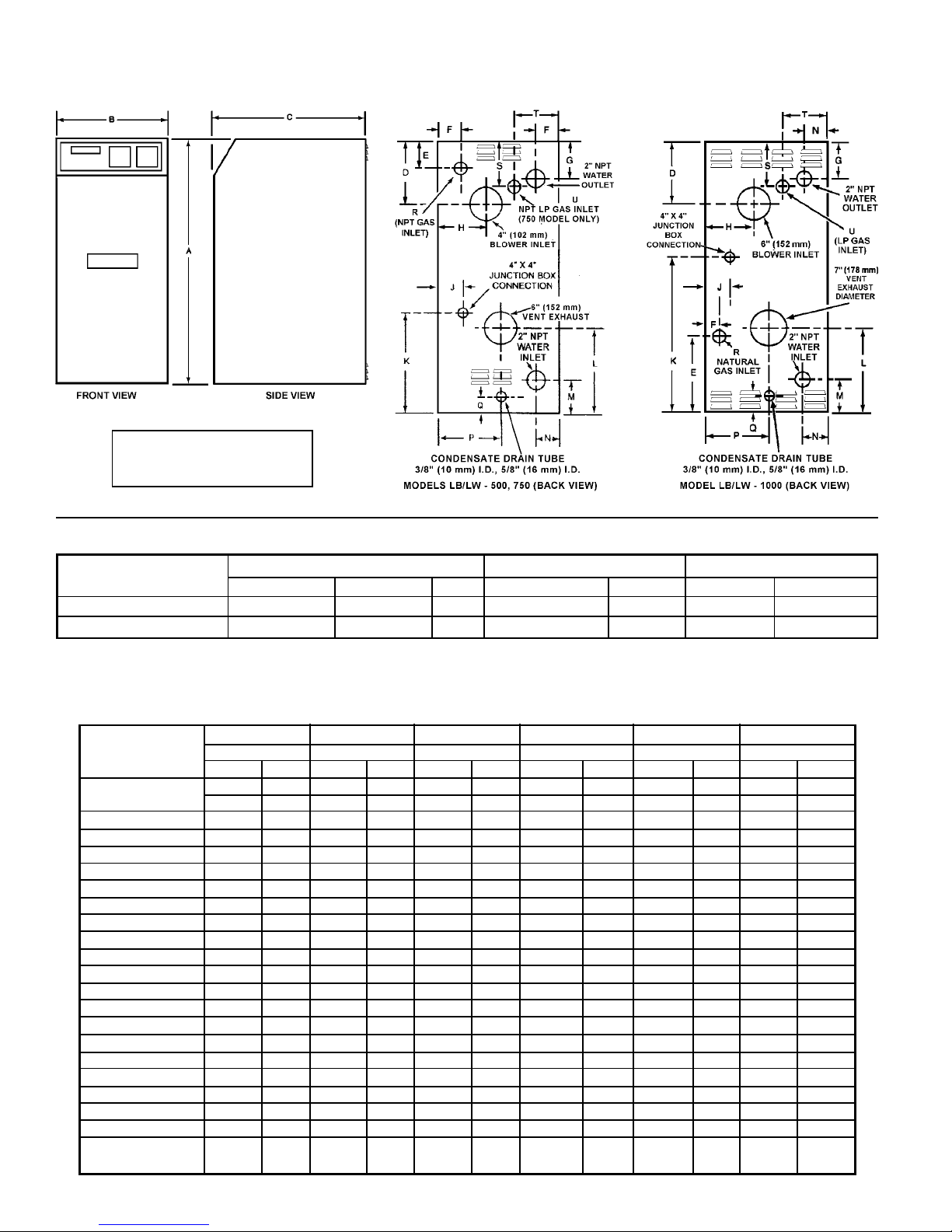
Minimum clearances to combustibles:
• 4” (102 mm) rear
• 0” (0 mm) top & sides
• 6” (152 mm) vent
ROUGH-IN DIMENSIONS
T ABLE 1, GAS AND ELECTRICAL CHARACTERISTICS
Manifold Pressure Maximum Supply Pressure Electrical Characteristics
Model Type of Gas Inches W.C. kP a Inches W.C. kPa Volts/Hz Amperes
LB/LW-500, 750, 1000 NATURAL 3.5 0.87 13.8 3.44 120/60 30
LB/LW-500, 750, 1000 PROP ANE 10 2.49 13.8 3.44 120/60 30
Minimum Supply Pressure, Natural Gas: 7.0 inches W.C. (1.74 kPa)
Minimum Supply Pressure, Propane Gas: 11.0 inches W.C. (2.74 kPa)
Minimum Pressures must be maintained under both load and no load (static and dynamic) conditions.
TABLE 2, ROUGH-IN DIMENSIONS
Models LB/LW-500 LB/LW-500 LB/LW-750 LB/LW-750 LB/LW-1000 LB/LW-1000
Gas Type Natural Gas Propane Gas Natural Gas Propane Gas Natural Gas Propane Gas
Dimensions inches m m inches m m inches m m inches mm inches m m inches m m
Exhaust Vent Diam. 6 152 6 152 6 152 6 152 7 178 7 178
Blower Inlet Diam. 4 102 4 102 4 102 4 102 6 152 6 152
A 53 1346 53 1346 53 1346 53 1346 60 1/2 1537 60 1/2 1537
B 23 584 23 584 23 584 2 3 584 27 1/8 689 27 1/8 689
C 32 813 32 813 32 8 13 32 813 38 3/16 9 70 38 3/16 970
D 13 1/2 343 13 1/2 343 13 1/2 343 13 1/2 343 13 3/4 349 13 3/4 349
E 4 3/8 111 4 3/8 111 4 3/8 111 - - 15 1/2 394 - F 3 1/4 83 3 1/4 8 3 3 1/4 83 - - 3 1/4 83 - -
G 6 3/8 162 6 3/8 162 6 3/8 16 2 6 3/8 162 8 1/8 206 8 1/8 206
H 7 1/2 191 7 1/2 191 7 1/2 1 91 7 1/2 191 8 1/4 210 8 1/4 210
J 3 1/2 89 3 1/2 89 3 1/2 89 3 1/2 89 3 1/2 89 3 1/2 89
K 19 483 19 483 19 483 19 483 36 914 36 914
L 14 1/2 359 14 1/2 359 11 1/4 286 11 1/4 286 12 318 12 318
M 5 127 5 127 5 127 5 127 6 3/4 171 6 3/4 171
N 5 1/4 133 5 1/4 133 5 1/4 1 33 5 1/4 133 4 1/8 105 4 1/8 105
P 11 1/2 292 11 1/2 292 11 1/2 292 11 1/2 292 13 3/8 340 13 3/8 340
Q 2 5 1 2 5 1 2 51 2 51 2 1/4 57 2 1/4 57
R 1 NPT 1 NPT 1 NPT - - 1 1/4 NPT - S ------11 3/4298--11 7/8302
T ------6 1/2165--7 5/8194
U ----- - 1NPT--1 1/4NPT
Approx. Shipping 425 lbs 193 Kg. 425 lbs 193 Kg. 528 lbs 240 Kg. 528 lbs 240 Kg. 934 lbs 424 Kg. 934 lbs 424 Kg.
Weight
2
Page 3
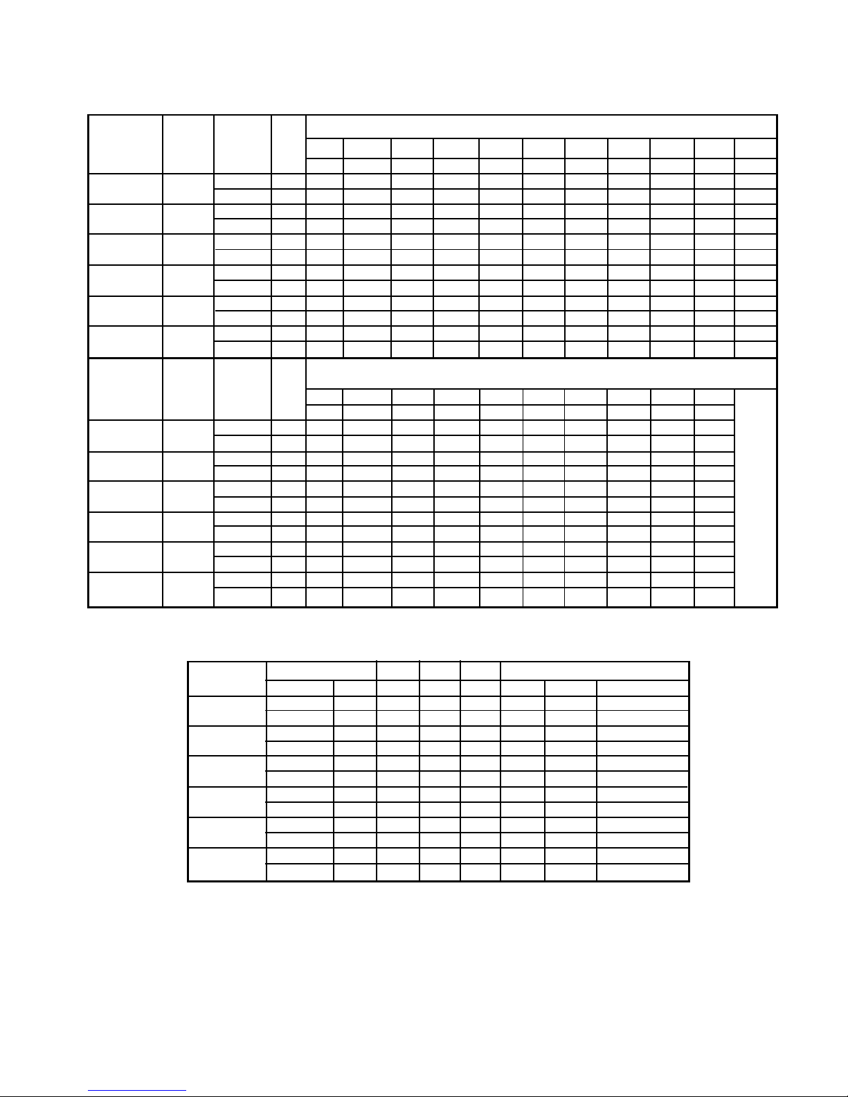
ROUGH-IN DIMENSIONS (Continued)
TABLE 3, RECOVER Y CAP ACITIES
U.S. Gallons/Hr and Litres/Hr at TEMPERATURE RISE INDICATED
GAS INPUT F° 18F° 20F° 30F° 36F° 40F° 50F° 54F° 60F° 70F° 72F°
MODEL TYPE BTUH KW C° 10C° 11C° 17C° 20C° 22C° 28C° 30C° 33C° 39C° 40C°
LB/LW-500 Natural 500,000 GPH 3030 2727 1818 1515 1364 1091 1010 909 779 758
146 LPH 11471 10324 6882 5735 5162 4129 3824 3441 2950 2868
LB/LW-500 Propane 450,000 GPH 2727 2455 1636 1364 1227 982 909 818 701 682
132 LPH 10324 9291 6194 5162 4646 3716 3441 3097 2655 2581
LB/LW-750 Natural 750,000 GPH 4545 4091 2727 2273 2045 1636 1515 1364 1169 1136
220 LPH 17206 15485 10324 8603 7743 6194 5735 5162 4424 4301
LB/LW-750 Propane 675,000 GPH 4091 3682 2455 2045 1841 1473 1364 1227 1052 1023
198 LPH 15485 13937 9291 7743 6968 5575 5162 4646 3982 3871
LB/LW-1000 Natural 1,000,000 GPH 6061 5455 3636 3030 2727 2182 2020 1818 1558 1515
293 LPH 22941 20647 13765 11471 10324 8259 7647 6882 5899 5735
LB/LW-1000 Propane 860,000 GPH 5212 4691 3127 2606 2345 1876 1737 1564 1340 1303
252 LPH 19729 17757 11838 9865 8878 7103 6576 5919 5073 4932
U.S. Gallons/Hr and Litres/Hr at TEMPERATURE RISE INDICATED
GAS INPUT F° 80F° 90F° 100F° 108F° 110F° 120F° 126F° 130F° 140F°
MODEL TYPE BTUH KW C° 44C° 50C° 56C° 60C° 61C° 67C° 70C° 72C° 78C°
LB/LW-500 Natural 500,000 GPH 682 606 545 505 496 455 433 420 390
146 LPH 2581 2294 2065 1912 1877 1721 1639 1588 1475
LB/LW-500 Propane 450,000 GPH 614 545 491 455 446 409 390 378 351
132 LPH 2323 2065 1858 1721 1689 1549 1475 1429 1327
LB/LW-750 Natural 750,000 GPH 1023 909 818 758 744 682 649 629 584
220 LPH 3871 3441 3097 2868 2816 2581 2458 2382 2212
LB/LW-750 Propane 675,000 GPH 920 818 736 682 669 614 584 566 526
198 LPH 3484 3097 2787 2581 2534 2323 2212 2144 1991
LB/LW-1000 Natural 1,000,000 GPH 1364 1212 1091 1010 992 909 866 839 779
293 LPH 5162 4588 4129 3824 3754 3441 3277 3176 2950
LB/LW-1000 Propane 860,000 GPH 1173 1042 938 869 853 782 745 722 670
252 LPH 4439 3946 3551 3288 3228 2959 2818 2732 2537
TABLE 4, HEAD LOSS at FLOW RA TES/MINUTE and TEMPERA TURE RISE SHOWN
INPUT F° 18F° 20F° HEAD LOSS Boiler
MODEL BTUH KW C° 10C° 11.1C° Feet Metres Inlet & Outlet
LB/L W-500 500,000 G P M 50 45 10 2” N PT
Natural 146 LPM 189 172 3.0
LB/L W-500 450,000 G P M 45 41 8.4 2” N PT
Propane 132 LPM 170 155 2.6
LB/L W-750 750,000 G P M 75 68 10.1 2” N PT
Natural 220 LPM 284 258 3.1
LB/L W-750 675,000 G P M 67 61 8.7 2” N PT
Propane 198 LPM 255 232 2.7
LB/LW -1000 1,000,000 G P M 100 91 8.9 2” NPT
Natural 293 LPM 378 344 2.7
LB/LW -1000 860,000 G P M 86 78 6.7 2” NPT
Propane 252 LPM 325 296 2.0
The ideal flow rate through the Legend models is considered to be the flow rate that results in
a 20 F° temperature rise across the unit. Table 4, shows head loss through units at
flow rate resulting in 20 F° rise. For head loss at other flow rates see sheet E202.2 in
A.O. Smith Architect’s & Engineer’s Manual.
3
Page 4

CONTENTS
Page
ROUGH-IN DIMENSIONS .............................................................. 2-3
FOREWORD .................................................................................. 4
Grounding Instructions ............................................................. 5
Inlet Water Considerations ........................................................5
Correct Gas ............................................................................. 5
Precautions .............................................................................. 5
Liquid Petroleum Models............................................................ 5
HIGH ALTITUDE INSTALLATIONS.................................................... 5
Field Installed Components ........................................................ 6
Panels and Covers ................................................................... 6
FEATURES / CONTROLS
Electronic Ignition Control .......................................................... 6
Hot Surface Ignitor.................................................................... 6
Blocked Flue Switch ................................................................. 6
Blower Prover Switch .............................................................. 7
Low Gas Switch ...................................................................... 7
Water Flow Switch................................................................... 7
Air Shutter................................................................................ 7
Blower Speed Control............................................................... 7
Combination Gas Control........................................................... 7
Manual Reset Limit (E.C.O.) ....................................................... 7
Automatic Reset Limit ............................................................... 7
On / Off Switch ........................................................................ 7
Circulating Pump ....................................................................... 8
T ank T emperature Control ......................................................... 8
Low Water Cutoff (not supplied) .............................................. 8
Drain V alve............................................................................... 8
Relief Valves ............................................................................ 8
INST ALLATION INSTRUCTIONS
Required Ability ........................................................................ 9
Location ................................................................................... 9
Chemical Vapor Corrosion ........................................................ 9
Installation Clearances .............................................................. 9
Leveling.................................................................................... 9
Air Requirements ...................................................................... 9
VENTING ..................................................................................... 10
Special Installation Considerations . ........................................ 11
Venting System Using AL 29-4C®........................................... 11
General Installation Requirements ........................................... 11
General Exhaust Vent Installation Procedure........................... 11
Connecting Vent to Boiler................................................... 11-13
Venting Supports.................................................................... 13
Vertical Installation Requirements............................................ 13
Horizontal Installation Requirements ...................................13-16
Direct Vent Installation Requirements ...................................... 16
SYSTEM INST ALLATION
General .................................................................................. 16
Page
Hot Water Heating (Hydronic) Equipment................................. 16
Internal Contaminants ............................................................. 17
Hot Water Supply System General Water Line Connections .... 17
Hard Water Conditions ............................................................ 19
Thermal Expansion (Closed System). ...................................... 19
T ank Probe Installation Procedure............................................ 19
T ank Probe Set-Point Adjustment ............................................ 19
GAS CONNECTIONS .................................................................... 19
Gas Supply Line Sizing ........................................................... 20
WIRING ........................................................................................ 20
SUGGESTED PIPE SIZING TABLES ............................................... 21
WIRING CONNECTION DIAGRAM .................................................. 22
SCHEMATIC DIAGRAM................................................................. 23
OPERATION ................................................................................. 24
General .................................................................................. 24
Filling and Purging for Heating Boiler Installation ...................... 24
Filling for Hot Water Supply Boiler Installation .......................... 24
Purging Gas Line .................................................................... 24
LIGHTING & OPERA TING INSTRUCTIONS ................................. 25-26
Inlet Gas Pressure .................................................................. 27
Manifold Pressure Connections .............................................. 27
Gas Pressure Regulators ....................................................... 27
Safety Checks........................................................................ 27
Water T emperature Regulation ................................................ 28
Sequence of Operation........................................................... 28
MAINTENANCE
Venting Maintenance .............................................................. 29
Burner and Flame Pattern ....................................................... 29
Burner Maintenance ............................................................... 30
Condensate Removal System ................................................. 30
DIA-SCAN II SELF-DIAGNOSTIC SYSTEM..................................... 30
Line Polarity Indicator.............................................................. 31
Fuse Protection ...................................................................... 31
Dia-Scan II Display Board
Operating Procedures ............................................................ 31
T emperature Set-Point Adjustment Procedure ......................... 32
Switching Differential Adjustment Procedure .......................... 32
Circulating Pump Adjustment Procedure .................................. 32
Display Current Mode ............................................................. 33
Display T otal Cycle Count........................................................ 33
T ank Probe T emp. Set-Point Adjustment Procedure.................. 33
Display Board LED Indicators .................................................. 34
TROUBLESHOOTING
Short Cycling .......................................................................... 34
Hard Starts............................................................................. 34
Troubleshooting Error Codes .................................................. 34
LIMITED WARRANTY ................................................................... 36
FOREWORD
This design complies with the latest edition of the ANSI Z21.13 CSA 4.9 low-pressure boiler standard.
Compliance under this standard implies that when the boiler
underwent test, the gas manifold and control assembly provided
on the boiler met safe lighting and other performance criteria.
Detailed installation diagrams are found in this manual. These
diagrams will serve to provide the installer a reference for the
materials and methods of piping necessary. It is essential that
all water, gas piping and wiring be installed as shown on the
diagrams. You should thoroughly read and understand this
manual before installation and/or operation of this boiler.
The factory warranty will be
improperly installed or operated.
®AL 29-4C is a registered trademark of Allegheny Ludlum Corporation.
void if the boiler(s) have been
In addition to these instructions, the boiler(s) shall be installed in
accordance with those installation regulations in force in the local
area where the installation is to be made. These shall be carefully
followed in all cases. Authorities having jurisdiction should be
consulted before installations are made.
In the absence of local codes, the installation must comply with
the latest editions, as follows:
In the United States:
The National Fuel Gas Code, ANSI Z223.1/NFPA 54and the
National Electric Code, NFPA 70.
In Canada:
The installation Code CAN/CSA B149.1-00 and the Canadian
Electric Code, CSA C22.2.
4
Page 5

These are available from the Canadian Standards Association,
8501 East Pleasant Valley Road, Cleveland, OH 44131, USA, or,
Canadian Gas Association Laboratories, 55 Scarsdale Road,
Don Mills, Ontario M3B 2R3, Canada.
GROUNDING INSTRUCTIONS
This boiler must be grounded in accordance with the National
Electrical Code and/or local codes. Boiler is polarity sensitive,
correct wiring is imperative for proper operation.
with age. For these reasons, the use of a propane gas detector
is recommended.
IF YOU EXPERIENCE AN OUT OF GAS SITUA TION, DO NOT TRY
TO RELIGHT APPLIANCES YOURSELF. Call your local service
agent. Only trained LP professionals should conduct the required
safety checks in accordance with industry standards.
HIGH AL TITUDE INST ALLATIONS
This boiler must be connected to a grounded metal, permanent
wiring system, or an equipment grounding conductor must be
run with the circuit conductors and connected to the equipment
grounding terminal or lead on the boiler.
INLET WATER CONSIDERATIONS
T o minimize the amount of condensate, a minimum inlet water
temperature to the heat exchanger of 140°F (60°C) shall be
maintained. This temperature can be acquired by returning 140°F
(60°C) water from the remote storage tank to the boiler or by
incorporating a by-pass loop between the boiler’s inlet and outlet
connections.
Circulating water through the boiler and to the remote storage
tank (if applicable) is accomplished by a built-in pump on LW
models only. For hot water heating systems using the LB model,
the circulating pump is NOT provided and must be field installed.
CORRECT GAS
MAKE SURE THE GAS ON WHICH THE BOILER WILL OPERA TE
IS THE SAME AS THAT SPECIFIED ON THE BOILER RATING
PLATE. DO NOT INSTALL THE BOILER IF EQUIPPED FOR A
DIFFERENT TYPE OF GAS — CONSUL T YOUR SUPPLIER.
PRECAUTIONS
IF THE UNIT IS EXPOSED TO THE FOLLOWING , DO NOT OPERA TE
UNTIL ALL CORRECTIVE STEPS HAVE BEEN MADE BY A
QUALIFIED SERVICEMAN:
1. EXPOSURE TO FIRE.
2. IF DAMAGED.
3. FIRING WITHOUT WA TER.
4. SOOTING.
IF THE BOILER HAS BEEN EXPOSED TO FLOODING , IT MUST BE
REPLACED.
LIQUID PETROLEUM MODELS
Boilers for propane or liquefied petroleum gas (LPG) are different
from natural gas models. A natural gas boiler will not function
safely on LP gas and no attempt should be made to convert a
boiler from natural gas to LP gas.
LP gas must be used with great caution. It is highly explosive
and heavier than air. It collects first in the low areas making its
odor difficult to detect at nose level. If LP gas is present or even
suspected, do not attempt to find the cause yourself. Leave the
building, leaving doors open to ventilate, then call your gas
supplier or service agent. Keep area clear until a service call has
been made.
At times you may not be able to smell an LP gas leak. One cause
is odor fade, which is a loss of the chemical odorant that gives LP
gas its distinctive smell. Another cause can be your physical
condition, such as having a cold or diminishing sense of smell
WARNING
INSTALLATIONS ABOVE 2000 FEET (600 M) REQUIRE
REPLACEMENT OF THE BURNER ORIFICE IN ACCORDANCE
WITH SECTION 8.2.1 OF THE NATIONAL FUEL GAS CODE (ANSI
Z223.1). FAILURE TO REPLACE THE ORIFICE WILL RESUL T IN
IMPROPER AND INEFFICIENT OPERA TION OF THE APPLIANCE
RESUL TING IN THE PRODUCTION OF INCREASED LEVELS OF
CARBON MONOXIDE GAS IN EXCESS OF SAFE LIMITS WHICH
COULD RESULT IN SERIOUS PERSONAL INJURY OR DEA TH.
Ratings specified by manufacturers for most appliances apply
for elevations up to 2000 feet (600 m). For elevations above 2000
feet (600 m), ratings must be reduced at the rate of 4% for each
1000 feet (300 m) above sea level. For example, if a boiler is
rated at 500,000 Btu/hr. at sea level, to rate the boiler at 4000 feet
(1200 m), the original rating is reduced by 16 percent (4 x 4%) to
a rating of 420,000 Btu/hr.
The input reduction is primarily achieved by reducing the size of
the main burner orifice. T o do this, the main burner orifices require
replacement with an orifice sized for the particular installation
elevation. Part number for gas orifices for altitudes up to 4000
feet (1220 m) are given in Table 5. Orifices for higher altitudes
are special order and may be obtained from A. O. Smith Water
Products Company. When ordering, be sure to state the model
number and the altitude of the location where the boiler is installed.
TABLE 5. LEGEND 2000 ORIFICE T ABLE
Natural Gas Propane Size Elevation
Model Part No. Part No. (In.) (Ft.)
LB/LW-500 *191884-0 — 0.391 0-2000
LB/LW-500 191884-1 — 0.384 2001-3000
LB/LW-500 191884-2 — 0.374 3001-4000
LB/LW-500 — 192741-0 0.229 0-2000
LB/LW-500 -- 192741-1 0.226 2001-3000
LB/LW-500 -- 192741-2 0.223 3001-4000
LB/LW-750(USA) *191884-3 -- 0.484 0-2000
LB/LW-750(USA) 191884-5 -- 0.469 2001-3000
LB/LW-750 USA 191884-7 -- 0.461 3001-4000
LB/LW-750 CAN *191884-11 -- 0.464 0-2000
LB/LW-750 CAN 191884-12 -- 0.450 2001-3000
LB/LW-750 CAN 191884-13 -- 0.443 3001-4000
LB/LW-750 -- 192741-3 0.286 0-2000
LB/LW-750 -- 192741-4 0.282 2001-3000
LB/LW-750 -- 192741-6 0.278 3001-4000
LB/LW-1000 *192222-0 -- 0.555 0-2000
LB/LW-1000 192222-1 -- 0.537 2001-3000
LB/LW-1000 192222-2 -- 0.533 3001-4000
LB/LW-1000 -- *192739-0 0.333 0-2000
LB/LW-1000 -- 192739-1 0.329 2001-3000
LB/LW-1000 -- 192739-2 0.325 3001-4000
*Factory installed orifice.
Upon completion of derating of the boiler, adjustment to the gas
pressure regulator may be required. See GAS PRESSURE
REGULATORS in this manual for inlet and manifold pressure
requirements.
Also, due to the input rating reduction required at high altitudes,
the output rating of the appliance is also reduced and should be
compensated for in the sizing of the equipment for applications.
5
Page 6
NOTE: Some gas utility companies derate their gas for altitude,
making it unnecessary to install high altitude orifices. Call the
local gas utility company to verify BTU content.
FIELD INSTALLED COMPONENTS
When installing the boiler, the following components MUST be
used, if applicable:
1) Circulating Pump (Hydronic)
2) Tank Temperature Control (Hot Water Supply)
3) Loop Temperature Control (Hydronic)
4) Low Water Cutoff Device
5) Relief Valve
6) Pressure Gauge
7) Manual Gas Shutoff Valve (Supply)
Check the FEATURES AND CONTROLS section for further
information.
system monitors the burner flame through the principle of flame
rectification. If a flame is not verified, the gas valve is immediately
closed.
FIGURE 2. FIGURE 3.
FIGURE 1.
P ANELS AND COVERS
All panels and covers (e.g. control and junction box covers; front,
side and rear panels of boiler) MUST be in place after service
and/or before operation of the boiler. This will ensure that all gas
ignition components will be protected from water.
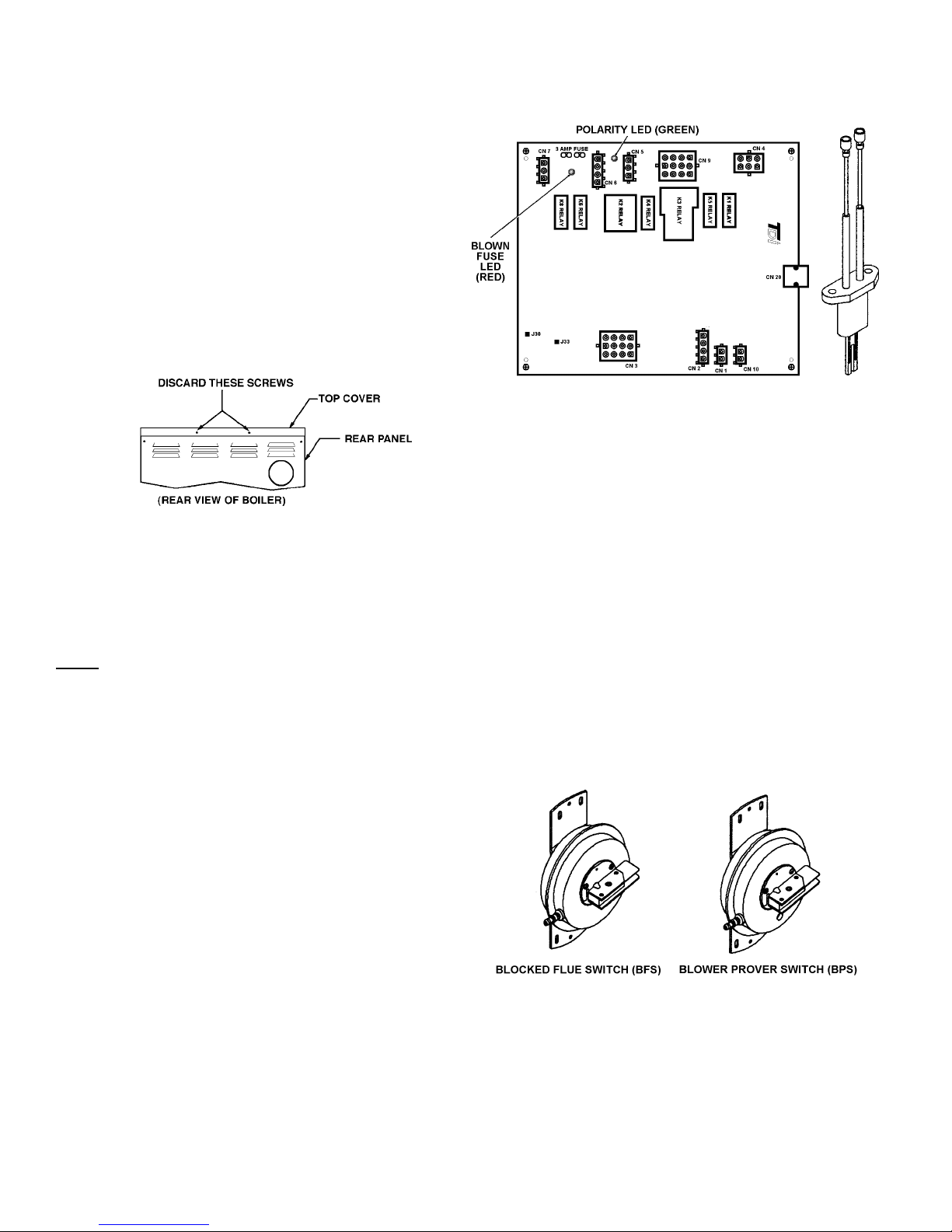
NOTE: Remove the two (2) sheet metal screws from the rear of
the top cover and discard them, see fig 1. This will allow removal
of the top cover without the use of tools. Also, remove the sheet
metal screw from the bottom of the front panel.
FEATURES/CONTROLS
The Legend 2000® is a low-pressure boiler (Category IV) to be
used as either hot water supply (domestic/commercial water
heating) or hot water heating (hydronic) application. Category IV
boilers operate with a positive vent pressure and with a vent gas
temperature less than 140°F (60°C) above its dew point. Category
IV appliances are often termed “High Efficiency” appliances.
The control board provides a pre-purge period of twenty (20)
seconds and a post-purge period of twenty-five (25) seconds.
The flame establishing period is four (4) seconds.
This control is non-adjustable. Any attempts to modify the
performance, other than those listed in this manual, voids the
control warranty.
The 24 VAC circuitry of the ignition control system is protected
with a 3-amp fuse. If the fuse opens, a red LED located near the
fuse will light.
HOT SURFACE IGNITOR
The Hot Surface Igniter, fig. 3, is a device that ignites the main
burner by high temperature (>1800°F) [982°C]. The igniter is
made of recrystallized silicon carbide, and when 120 VAC is
applied to the igniter, sufficient heat is generated to ignite the
main burner. Although improvements have been made to
strengthen the igniter, it is still fragile and care must be taken in
handling the igniter to prevent breakage.
This high efficiency is obtained from a unique heat exchanger
design consisting of multiple integral high-finned copper tubes
brazed in parallel into two brass manifolds. The condensate
from the heat exchanger flows downward into the vent collector
housing then into the plastic condensate drain and through the
attached flexible hose which must terminate at a suitable floor
drain.
ELECTRONIC IGNITION CONTROL
The Legend 2000® is controlled by the WHC 1502 ignition system,
fig. 2. The WHC 1502 is a solid-state ignition control that ignites
the main burner by energizing the Hot Surface Ignitor, fig. 3. The
ignition control system continuously monitors the current of the
ignitor and will not allow gas to enter the main burner until current
flow reaches the preset ignition temperature threshold. Once
the ignition threshold has been reached, the control system will
open the gas valve(s). After the main burner ignites, the control
FIGURE 4.
BLOCKED FLUE SWITCH
The Blocked Flue Switch (BFS) fig. 4, is a single-pole, normally
closed pressure switch that will open its contacts when a rising
positive pressure of 1.0 in. w.c. (0.25 kPa) is encountered. The
contacts will close when the pressure falls below the fixed set
point of 1.0 in. w.c. (0.25 kPa) The BFS monitors the pressure
inside the venting system. If the venting system is blocked in
such a way that the build up in pressure exceeds the setting of
6
Page 7
the BFS, the main burner is extinguished (if boiler is running) or
the boiler will not start up.
BLOWER PROVER SWITCH
The Blower Prover Switch (BPS) fig. 4, is similar in construction
to the BFS. It is a single-pole, normally open pressure switch
that will close its contacts when a rising positive pressure of
1.0 in. w.c. (0.25 kPa) is encountered. The contacts will open
when the pressure falls below the fixed set point of 1.0 in. w.c.
(0.25 kPa) The BPS monitors the pressure inside the blower
elbow. If the blower is not operating at a sufficient blowing cap acity ,
the main burner is extinguished (if boiler is running) or the boiler
will not start up.
LOW GAS SWITCH
The Low Gas Switch (LGS) fig. 5, is a single-pole, normally open
pressure switch that will close its contacts when a rising pressure
of 5.0 in. w.c. (1.24 kPa) is encountered. The contacts will open
when the pressure falls below the fixed set point of 5.0 in. w.c.
(1.24 kPa) The LGS monitors the gas supply pressure to the
boiler. If the gas supply falls below 5.0 in. w.c. (1.24 kPa), the
main burner is extinguished (if boiler is running) or the boiler will
not start up.
AIR SHUTTER
The blower is equipped with an air shutter assembly for fine
adjustment of the air to gas ratio The assembly consists of a
shutter flange and the air shutter. The shutter may require
adjustment to achieve ideal start-up characteristics when fine tuning
the boiler for correct combustion specifications. Refer to the
Start-Up Procedures, part number 192077 Rev. 1, for the proper
combustion specifications and limits. If necessary, the shutter
may be adjusted by loosening the two nuts used to hold the shutter
and blower adapter assembly in place on the inlet of the blower.
Once the unit is set to the specifications called for in the Start-Up
Procedures, tighten the nuts to lock the shutter in place.
BLOWER SPEED CONTROL
The Blower Speed Control (BSC) permits variation of speed of
the blower during boiler (LB/LW-500 only) start-up. When the
1502 Control Board energizes the igniter, the BSC will lower the
speed (RPM) of the blower to a preset level. This lower speed
will be maintained until the igniter is de-energized by the Control
Board. Then, the blower will return to its normal operating speed.
COMBINATION GAS CONTROL
The Combination Gas Control (CGC) is a gas valve or valves that
controls the supply of gas to the main burner during operation of
the boiler. The CGC includes a manual main shutoff valve, two
(2) automatic valves and a pressure regulator, see figure 15.
FIGURE 5. LOW GAS SWITCH (LGS)
WATER FLOW SWITCH
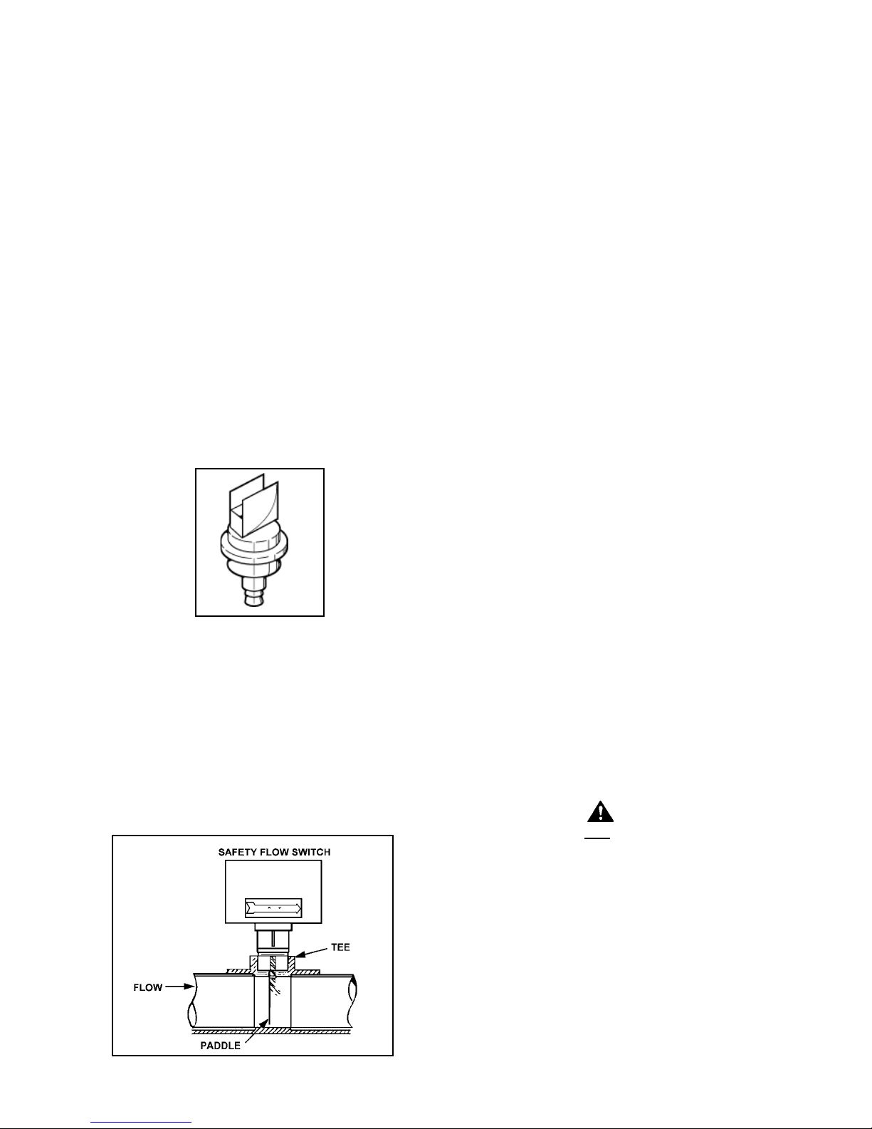
The Water Flow Switch (WFS) fig. 6, is installed at the boiler water
outlet to prevent main burner operation in the event of inadequate
water flow through the boiler. The WFS is a single-pole, normally
open switch that will close its contacts when an increasing water
flow rate of approximately 25 GPM (1.61 lps) is encountered. The
contacts will open when the flow rate drops below this setting,
extinguishing the main burner flames (if boiler is running) or the
boiler will not start up .
The two-position gas control knob has “ON” and “OFF” positions
that allows or prevents the flow of gas to the main burner,
respectively. The first automatic valve is solenoid operated and
opens and closes when the main valve terminal on the Control
Board is energized or de-energized, respectively. The second
automatic valve is diaphragm operated and opens under control
of the pressure regulator and closes if gas or power supply is
interrupted. The pressure regulator is adjustable and maintains
an almost constant gas outlet pressure under wide fluctuations
in gas supply pressure.
MANUAL RESET LIMIT (E.C.O)
This device prevents the water temperature from exceeding 250°F
(121°C). It is located in the outlet waterway within the outlet
temperature sensing device and is monitored by the Control
Board. Commonly referred to as the “emergency cut out”, it is a
manually resettable control. The “ADJUST”, “SELECT” or
“ENTER/RESET” button on the display board must be depressed
to reset the unit if the water temperature reaches this limit. See
figure 20.
CAUTION
LIMIT CONTROLS ARE NOT TO BE USED AS A THERMOST A T OR
OPERA TING CONTROL.
AUTOMATIC RESET LIMIT
This limit is a safety device in series with the ignition system. Set
the limit control to a minimum of 30°F (16°C) above the maximum
designed system temperature. If the boiler outlet water
temperature should exceed the automatic reset limit setting, the
main gas valves will close. The automatic reset limit control is
factory set at 180°F (82°C) and has an adjustable range from
110 to 240°F (43° to 116°C). The operating differential is also
adjustable from 5 to 50°F (3° to 28°C).
FIGURE 6. WA TER FLOW SWITCH (WFS)
ON/OFF SWITCH
The ON/OFF Switch is a single-pole, single-throw rocker switch.
This switch provides 120V from the line source to the boiler.
7
Page 8
CIRCULATING PUMP
DRAIN V AL VE
HOT WA TER SUPPLY SYSTEMS, the circulating pump is integral
to the LW models. This pump has been lubricated at the factory,
and future lubrication should be in accordance with the motor
manufacturer’s instructions provided as a supplement to this
manual.
FOR HOT WA TER HEA TING SYSTEMS-LB MODELS, the circulating
pump is NOT provided and must be obtained and installed in the
field.
NOTE: I f a system pump is to be installed on a Legend LB
model, the maximum rating of the pump motor must
not exceed 1 hp.
TANK TEMPERATURE CONTROL
A tank probe is provided with LW models to be used for tank
temperature regulations. The temperature setting for the tank is
set through the display.
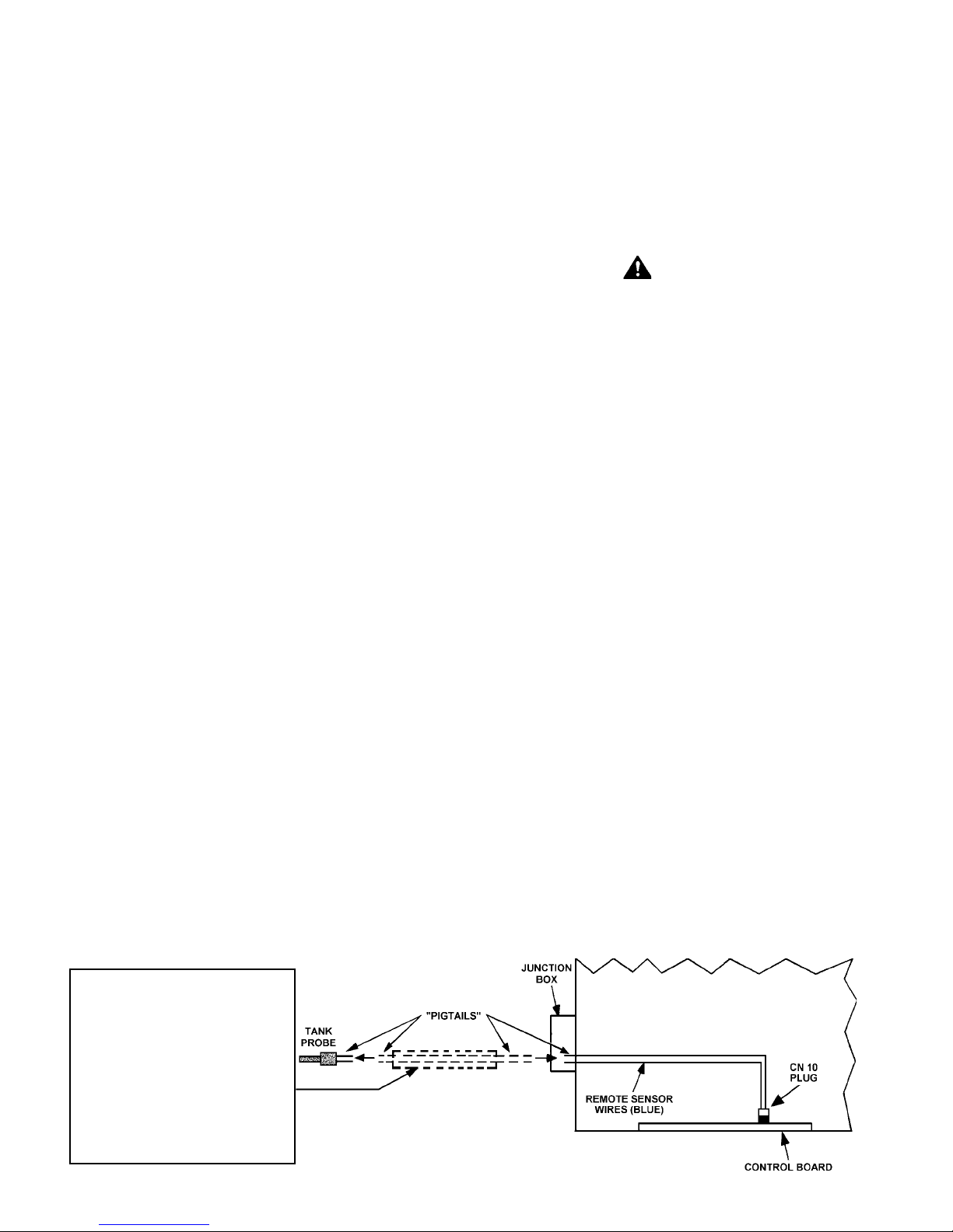
Refer to figs. 7, 13, 14 and 16 for connecting the tank probe to the
boiler.
See TEMPERATURE SET POINT ADJUSTMENT PROCEDURE
for further instructions.
FOR HOT WA TER SUPPLY SYSTEMS, the boiler is supplied with
a Tank Probe to be field installed in the storage tank. Alternate
methods of temperature control, if desired, must be supplied by
the installer.
A change in water temperature in the storage tank lower than the
Tank Temperature Control setting will cause the sensor to close
its contacts and consequently, energize the boiler.
If the Tank Probe or Temperature Control is out of calibration,
replace it with a new one; do not attempt to fix this control.
A drain valve is factory installed in the heat exchanger manifold.
This will help to drain the heat exchanger.
Additional drain valves must be obtained and installed on each
boiler and tank for draining purposes, see figures 12, 13 and 14.
SAFETY RELIEF V AL VE
Your local code authority may have other specific safety relief
valve requirements not covered below.
WARNING
THE PURPOSE OF A SAFETY RELIEF VALVE IS TO AVOID
EXCESSIVE PRESSURE OR TEMPERA TURE INTO THE STEAM
RANGE WHICH MA Y CAUSE SCALDING AT FIXTURES, TANK
EXPLOSION, SYSTEM OR BOILER DAMAGE.
TO A VOID SCALDING OR W ATER DAMAGE, A DRAIN LINE MUST
BE CONNECTED TO A SAFETY RELIEF VALVE TO DIRECT
DISCHARGE TO A SAFE LOCATION. A DRAIN LINE MUST NOT BE
REDUCED FROM THE SIZE OF THE VAL VE OUTLET AND IT MUST
NOT CONTAIN ANY V AL VES BETWEEN THE BOILER AND THE
RELIEF VA LVE OR THE RELIEF V AL VE AND THE DRAIN EXIT . IN
ADDITION, THERE SHOULD NOT BE ANY RESTRICTIONS IN A
DRAIN LINE NOR SHOULD IT BE ROUTED THROUGH AREAS
WHERE FREEZING CONDITIONS MIGHT OCCUR. DO NOT THREAD
OR CAP THE DRAIN LINE EXIT . RESTRICTING OR BLOCKING A
DRAIN LINE WILL DEFEAT THE PURPOSE OF THE SAFETY RELIEF
V ALVE AND MA Y CREA TE AN UNSAFE CONDITION. INST ALL A
DRAIN LINE WITH A DOWNWARD SLOPE SUCH THA T IT WILL
NATURALL Y DRAIN ITSELF .
If any pressure relief valve is replaced, the replacement valve
must comply with the latest version of the ASME Boiler and
Pressure Vessel Code, Section IV (“HEATING BOILERS”).
NOTE: If you are using an L W model in a hydronic (space heating)
application, do not use the tank probe as a loop temperature
regulation device. The tank probe’s maximum setting is
190°F (88°C). Therefore, 24 VAC connections (red/green wires)
are provided in the rear junction box for an alternate device. The
J33 board jumper must be removed to use a 24 VAC temperature
regulation device (See figures 21 and 22).
LOW WATER CUTOFF (Not Supplied)
If low water protection is required by the authorities having
jurisdiction, a low water cutoff switch should be installed next to
the boiler in the outlet water line as shown in figure 12. The
switch should receive periodic (every six months) inspection to
assure proper operation. A Low Water Cutoff device of the float
type should be flushed every six months.
Encase field-supplied wires
between tank probe and junction
box with 1/2" field supplied
conduit. "Pigtails" of fieldsupplied wires should be spliced
to "pigtails" of tank probe and
connected to 24V AC junction box.
This conduit and wiring should be
separate from any other conduit/
wiring to guard against EMI
(electromagnetic interference).
Select a relief valve with a discharge rating NOT LESS than the
boiler input, and a set pressure NOT EXCEEDING the working
pressure of any component in the system.
FOR HOT WATER SUPPLY SYSTEMS, the boilers are shipped
with a 125 psi (860 kPa) pressure relief valve that must be installed
in the water outlet as near to the boiler as possible.
This ASME-rated valve has a discharge capacity that exceeds the
maximum boiler input rating and a pressure rating that does not
exceed the maximum working pressure shown on the boiler rating
plate.
In addition, a CSA design-certified and ASME-rated temperature
and pressure (T & P) relief valve must be installed on each and
every water storage tank in the hot water supply system.
FIGURE 7. TANK PROBE INST ALLA TION
8
Page 9

The T & P relief valve must comply with the applicable construction
provisions of the
Shutoff Devices for Hot Water Supply Systems, ANSI Z21.22-1999
or CAN/CSA-B149.1-00, or most recent edition. The T & P relief
valve must be of the automatic reset type and not embody a singleuse type fusible plug, cartridge or linkage.
The T & P relief valve should have a temperature rating of 210°F
(99°C), a pressure rating NOT exceeding the lowest rated working
pressure of any system component, and a discharge capacity
exceeding the total input of the water boilers supplying water to
the storage tank.
Locate the T & P relief valve (a) in the top of the tank, or (b) in the
side of the tank on a centerline within the upper 6 inches (152
mm) of the top of the tank. See figures 13 and 14. The tapping
shall be threaded in accordance with the latest edition of the
Standard for Pipe Threads, General Purpose (inch), ANSI/ASME
B1.20.1. The location of, or intended location for, the T & P relief
valve shall be readily accessible for servicing or replacement.
Standard for Relief Valves and Automatic Gas
If the boiler is installed above radiation level, a Low Water Cutoff
Device must be installed in the boiler outlet at the time of
installation.
CHEMICAL VAPOR CORROSION
Water boiler corrosion and component failure can be caused by
the heating and breakdown of airborne chemical vapors. Spray
can propellants, cleaning solvents, refrigerator and air
conditioning refrigerants, swimming pool chemicals, calcium and
sodium chloride (water softener salt), waxes, and process
chemicals are typical compounds which are potentially corrosive.
These materials are corrosive at very low concentration levels
with little or no odor to reveal their presence.
Products of this sort should not be stored near the boiler. Also,
air which is brought in contact with the water boiler should not
contain any of these chemicals. If necessary, uncontaminated
air should be obtained from remote or outside sources. Failure
to observe this requirement will void the warranty.
FOR HOT WATER HEATING SYSTEMS, the boilers are shipped
with a 50 psi (345 kPa) pressure relief valve. This relief valve
must be installed in the water outlet as near to the boiler as
possible.
INST ALLA TION INSTRUCTIONS
REQUIRED ABILITY
INSTALLATION OR SERVICE OF THIS BOILER REQUIRES
ABILITY EQUIV ALENT T O THAT OF A LICENSED TRADESMAN
IN THE FIELD INVOL VED. PLUMBING, AIR SUPPLY, VENTING,
GAS SUPPLY AND ELECTRICAL WORK ARE REQUIRED.
LOCATION
When installing the boiler, consideration must be given to proper
location. The location selected should provide adequate air
supply and be as centralized with the piping system as possible.
THE BOILER MUST NOT BE INSTALLED ON CARPETING.
THE BOILER SHOULD NOT BE LOCATED IN AN AREA WHERE IT
WILL BE SUBJECT TO FREEZING .
LOCATE IT NEAR A FLOOR DRAIN. THE BOILER SHOULD BE
LOCATED IN AN AREA WHERE LEAKAGE FROM THE BOILER OR
CONNECTIONS WILL NOT RESULT IN DAMAGE TO THE
ADJACENT AREA OR TO LOWER FLOORS OF THE STRUCTURE.
WARNING
THERE IS A RISK IN USING FUEL BURNING APPLIANCES SUCH
AS BOILERS IN ROOMS OR AREAS WHERE GASOLINE, OTHER
FLAMMABLE LIQUIDS OR ENGINE DRIVEN EQUIPMENT OR
VEHICLES ARE STORED, OPERATED OR REPAIRED.
FLAMMABLE VAPORS ARE HEAVY AND TRA VEL ALONG THE
FLOOR AND MA Y BE IGNITED BY SP ARKS CAUSING FIRE OR
EXPLOSION. SOME LOCAL CODES PERMIT OPERA TION OF GAS
APPLIANCES IF INSTALLED 18 INCHES (457 MM) OR MORE
ABOVE THE FLOOR. THIS MA Y REDUCE THE RISK IF LOCATION
IN SUCH AN AREA CANNOT BE A VOIDED.
WARNING
FLAMMABLE ITEMS, PRESSURIZED CONTAINERS OR ANY
OTHER POTENTIAL FIRE HAZARDOUS ARTICLES MUST NEVER
BE PLACED ON OR ADJACENT TO THE BOILER. OPEN
CONTAINERS OR FLAMMABLE MATERIAL SHOULD NOT BE
STORED OR USED IN THE SAME ROOM WITH THE BOILER.
INST ALLATION CLEARANCES
This boiler is approved for installation on combustible flooring in
an alcove with minimum clearances to combustibles of:
4" (102 mm) Rear; 0" (0 mm) Top and Sides; 6" (152 mm) Vent.
Two inch (51 mm) clearance is allowable from combustible
construction for hot water pipes.
Sufficient area should be provided at the front and rear of the unit
for proper servicing. Service clearances of 24" (610 mm) in front,
rear, top and left side are recommended. In a utility room
installation, the door opening shall be wide enough to allow the
boiler to enter or to permit the replacement of another appliance
such as a water heater.
LEVELING
Each unit should be checked after installation to be certain that it
is level.
If the unit is not level, obtain and insert shims under the nylon
protective feet at the frame base to correct this condition.
AIR REQUIREMENTS
WARNING
FOR SAFE OPERA TION, AN AMPLE SUPPL Y OF AIR MUST BE
PROVIDED FOR PROPER COMBUSTION AND VENTILA TION IN
ACCORDANCE WITH SECTION 8.3, AIR FOR COMBUSTION AND
VENTILA TION, OF THE
OR SECTION 7.4 OF CSA-B149.1-00 OR APPLICABLE
PROVISIONS OF THE LOCAL BUILDING CODES. AN INSUFFICIENT
SUPPL Y OF AIR WILL RESULT IN A YELLOW , LUMINOUS BURNER
FLAME, CAUSING CARBONING OR SOOTING OF THE FINNED HEAT
EXCHANGER AND CREA TING A RISK OF ASPHYXIATION. DO NOT
OBSTRUCT THE FLOW OF COMBUSTION AND VENTILA TION AIR.
UNCONFINED SPACE
In buildings of conventional frame, brick or stone construction,
unconfined spaces may provide adequate air for combustion.
If the unconfined space is within a building of tight construction
(buildings using the following construction: weather stripping,
heavy insulation, caulking, vapor barrier, etc.), air for combustion,
ventilation and draft hood dilution must be obtained from outdoors
9
NATIONAL FUEL GAS CODE, ANSI Z223.1
Page 10
or spaces freely communicating with the outdoors. The
installation instructions for confined spaces in tightly constructed
buildings must be followed to ensure adequate air supply.
CONFINED SPACE
Where power vented equipment is used in the same room as the
boiler, sufficient air openings must be supplied.
UNDERSIZED OPENINGS MAY RESULT IN INSUFFICIENT AIR
FOR COMBUSTION.
A. U.S. INSTALLA TIONS
When drawing combustion and dilution air from inside a
conventionally constructed building to a confined space, such a
space shall be provided with two permanent openings, ONE IN
OR WITHIN 12 INCHES (305 MM) OF THE ENCLOSURE TOP
AND ONE IN OR WITHIN 12 INCHES (305 MM) OF THE
ENCLOSURE BOTTOM. Each opening shall have a free area of
at least one square inch per 1000 Btu/hr (2,225 mm
the total input of all appliances in the enclosure, but not less than
100 square inches (645 cm
2
).
2
per kw) of
If the confined space is within a building of tight construction, air
for combustion, ventilation and draft hood dilution must be
obtained from outdoors. When directly communicating with the
outdoors or communicating with the outdoors through vertical
ducts, two permanent openings, located in the aforementioned
manner, shall be provided. Each opening shall have a free area
of not less than one square inch per 4000 Btu/hr (551 mm
2
per
kw) of the total input of all appliances in the enclosure. If horizontal
ducts are used, each opening shall have a free area of not less
than one square inch per 2000 Btu/hr (1,101 mm
2
per kw) of the
total input of all appliances in the enclosure.
B. CANADIAN INST ALLATIONS
Ventilation of the sp ace occupied by the boiler(s) shall be provided
by an opening for ventilation air at the highest practical point
communicating with outdoors. The total cross-sectional area
shall be at least 10% of the area of the combustion air opening
but in no case shall the cross-sectional area be less than
10 square inches (6500 mm
2
).
In addition to the above, there shall be permanent air supply
opening(s) having a cross-sectional area of not less than 1 square
inch per 7,000 BTUH (315 mm
BTUH
plus 1 square inch per 14,000 BTU (158 mm2/kW) in
2
/KW) up to and including 1,000,000
excess of 1,000,000 BTUH. This opening(s) shall be located at,
or ducted to, a point neither more than 18” (457 mm) nor less
than 6 inches (152 mm) above the floor level.
Where an exhaust fan is installed in the same room with the
boiler, sufficient openings for air must be provided in the walls.
UNDERSIZED OPENINGS WILL CAUSE AIR TO BE DRA WN INTO
THE ROOM THROUGH THE CHIMNEY OR OTHER OPENINGS,
CAUSING POOR COMBUSTION. SOOTING MA Y RESUL T WITH
AN INCREASED RISK OF ASPHYXIA TION.
VENTING
WARNING
THE INSTRUCTIONS IN THIS SECTION ON VENTING THE BOILER
MUST BE FOLLOWED TO AVOID CHOKED COMBUSTION OR
RECIRCULATION OF FLUE GASES. SUCH CONDITIONS CAUSE
SOOTING OR RISKS OF FIRE AND ASPHYXIATION.
VENT SIZING , INST ALLA TION AND TERMINA TION SHALL BE IN
ACCORDANCE WITH THIS INST ALLA TION MANUAL.
ALL ELECTRICAL POWER AND GAS MUST BE TURNED OFF
PRIOR TO ANY INSTALLA TION OF THE VENTING SYSTEM.
SPECIAL INST ALLATION CONSIDERA TIONS
The Legend 2000® is listed as a Category IV appliance and utilizes
a mechanical forced draft system. The vent system shall be
designed to prevent leakage of flue gases and condensate. The
condensate must be allowed to flow to a suitable drain. Since
the condensate is known to be detrimental to conventional vent
materials (galvanized steel, some stainless steels), the vent
material for the boiler’s exhaust shall be approved and certified
for the venting of low temperature condensing flue gasses. AL
®
is one such material.
29-4C
The exhaust gases of this boiler are generally only 15°-20°F (8°C
to 11°C) higher than the boiler’s operating temperature, much
lower than a standard boiler. In cold climates any water vapor
remaining in the flue gases will condense into a cloud of vapor at
the point where the vent system exits the building. Special
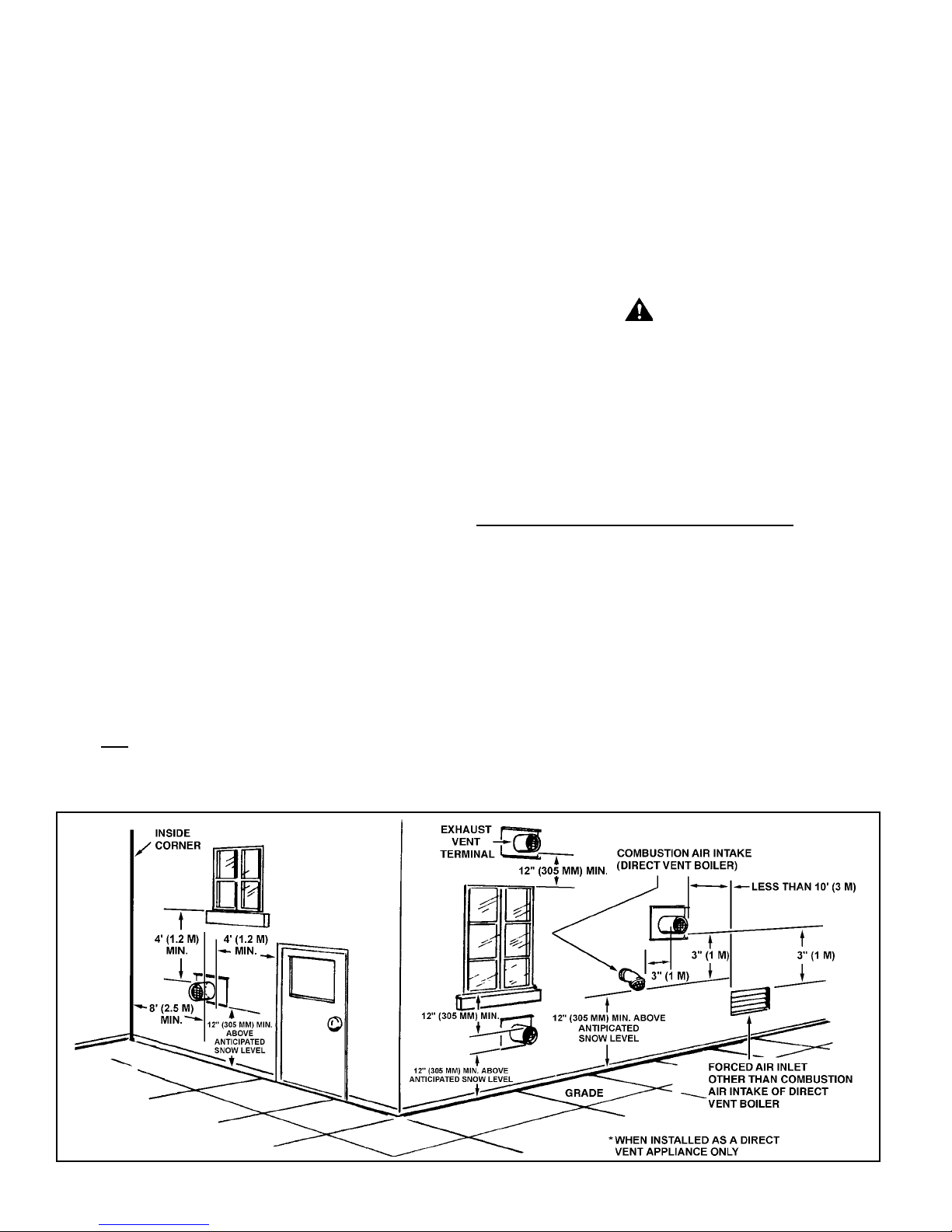
FIGURE 8. SIDEWALL EXHAUST VENTING
10
Page 11

consideration is recommended, before locating the vent
termination near walkways, windows and building entrances.
Direct venting into dead spaces such as; alleys, atriums and
inside corners can cause recirculation of flue gases. Recirculation
of flue gases will cause sooting, premature failure of the heat
exchanger and icing of the combustion air intake during severe
cold weather. To prevent the recirculation of flue gases, maintain
as much distance as possible between the combustion air intake
and the exhaust vent terminal. Due to large volumes of flue gases,
multiple boiler applications also require additional distance
between the intake and exhaust terminals.
VENTING SYSTEM USING AL 29-4C
The LEGEND 2000® may be installed in four separate orientations
depending on the requirements of the building and the appliance.
The installer must decide which method is most appropriate for
each installation. These orientations are:
1. Vertical Termination — vertical vent termination through un-
enclosed or enclosed areas with roof penetration, see fig. 9.
2. Through-the-Wall Termination (TWT) — horizontal vent
termination directly through an outside wall, see figure 9A.
3. Direct Vent — using TWT to exhaust flue products and PVC
piping to bring combustion air to the boiler from the outside,
see figures 11 and 11C.
4. Vertical Direct Vent — using a vertical vent termination to
exhaust flue products and PVC piping to bring combustion air
to the boiler from outside, see figures 11A and 11B.
GENERAL INST ALLA TION REQUIREMENTS
COMMOM VENTING LEGEND BOILERS.
Common venting of multiple Legend boilers are not allowed
except with either a U.L. or CSA approved power venter.
• All the vent pipe(s) and power venter must be sized by and
installed as per the recommendations of the power venter
manufacturer. Please see boiler’s wiring label for electrical
hook-up of power venter to the ignition control.
• When multiple Legend boilers are connected using a common power venter and common power venter and common
vent pipe; the power venter and vent piping should be sized to
maintain a -0.0 IWC to -0.04 IWC draft in the common vent
downstream of the boilers, when any one of or all boilers are
firing. A positive pressure of +.02 IWC to =.05 IWC should be
seen 12" above the boot tee of each unit when the unit is firing.
• All Venting material must be AL29-4C venting material.
• A factory start-up of the engineered power venting system must
be preformed by an authorized factory start-up agent of the
power venter system manufacturer.
• To assure proper boiler and power venter operation, both the
power venter start-up and A.O. Smith Authorized boiler start-up
must be performed simultaneously.
1. Failure to conform with any of these requirements may violate
local, state/provincial or federal codes as well as create
conditions which may cause catastrophic property damage or
personal injury . The vent system must terminate so that proper
clearances are maintained as cited in local codes or the latest
edition of the National Fuel Gas Code, ANSI Z223.1 or
CSA-B149.1-00 and latest addenda. The vent system must
not have external runs greater than that allowed by local codes
or the National Fuel Gas Code.
2. AL 29-4C® sections and fittings MUST be used for the entire
length of the exhaust system; alternatives such as galvanized
pipe, PVC, CPVC or Type B Vent sections must
3. Install a AL 29-4C
®
drain fitting as close as possible to the
not be used.
boiler vent connector outlet. See “CONNECTING VENT TO
BOILER” on the installation of this drain fitting.
4. Horizontal runs of vent pipe shall be securely supported by
adequately placed (approximately every 6 feet [2 m])
non-combustible hangers and/or slip joints suitable for the
weight and design of the material employed to prevent sagging
and to maintain a minimum upward slope of 1/4" per foot (21
®
mm) from the boiler to the vent terminal (see “VENTING
SUPPORTS” and figures 9A and 11).
The upward slope allows any build up of condensate to flow
back towards the boiler and drain fitting preventing the
accumulation of condensate. See “CONNECTING VENT TO
BOILER.”
EXCEPTION: The vent connector on the boiler is sloped
downward to direct condensate towards the “field-installed”
drain fitting.
5. All joints in the venting system MUST be sealed with RTV 106
or equivalent sealant.
6. NO other appliances may be interconnected to any part of this
venting system, including vent connectors which serve
appliances vented by NATURAL DRAFT.
7. The venting system must be planned so as to avoid possible
contact with concealed plumbing or electrical wiring inside
walls.
8. The venting system must be planned to maintain an airspace
clearance from combustibles of at least 6 inches (152 mm)
®
for any conduit and fittings of single wall AL 29-4C
vent and at
least 4 inches (102 mm) for any conduit and fittings of double
wall AL 29-4C® vent. Double wall AL 29-4C® vent must be
used when penetrating any floors, walls or ceilings and any
penetration must be properly fire stopped. All insulation
material must be removed from any wall, floor or ceiling cavity
for at least 4 inches (102 mm) from the conduit.
9. The venting system in a multi-family structure must be planned
to be enclosed when passing through occupied or unoccupied
spaces above the connected boiler. This enclosure is to be of
materials no less fire resistant than surrounding floors and
walls. It is recommended that the system be enclosed
whenever passing through occupied spaces.
GENERAL EXHAUST VENT INST ALLA TION PROCEDURE
Prior to beginning the installation of the vent system, determine
and obtain all parts required for the installation. Refer to the
DIRECT VENT KIT PAR TS LIST (p art no. 192109), for a list of the
vent sections and fittings.
Proper operation of the boiler and venting system is dependent
upon use of all specified parts and installation techniques; both
safety and proper performance of the system may suffer if
instructions are not followed.
CONNECTING VENT TO BOILER
At the outlet of the boiler vent, see figure 10, the AL 29-4C® Vent
Boot-T ee and Boot-Tee Drain Cover must be used as the transition
from the horizontal to vertical run. This is where the bottom most
support bracket should be located.
11
Page 12
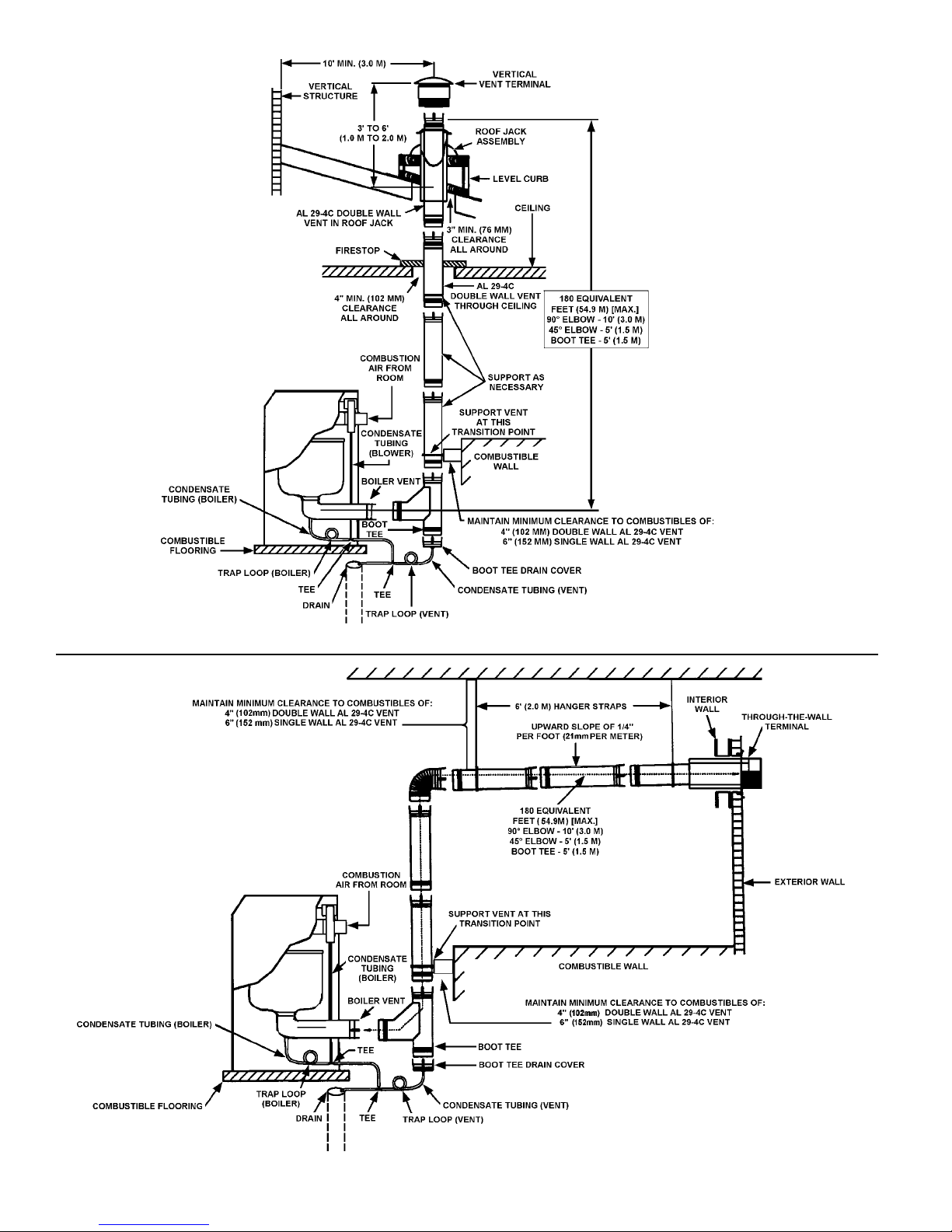
NOTES: If the exhaust vent terminal is
within 10’ (3.0 m) of a wall or parapet, it
must extend a minimum of 2’ (610 mm)
above the wall or parapet.
Joints are not joined to show vent pipe
orientation.
NOTES: Joints are not joined
to show vent pipe orientation.
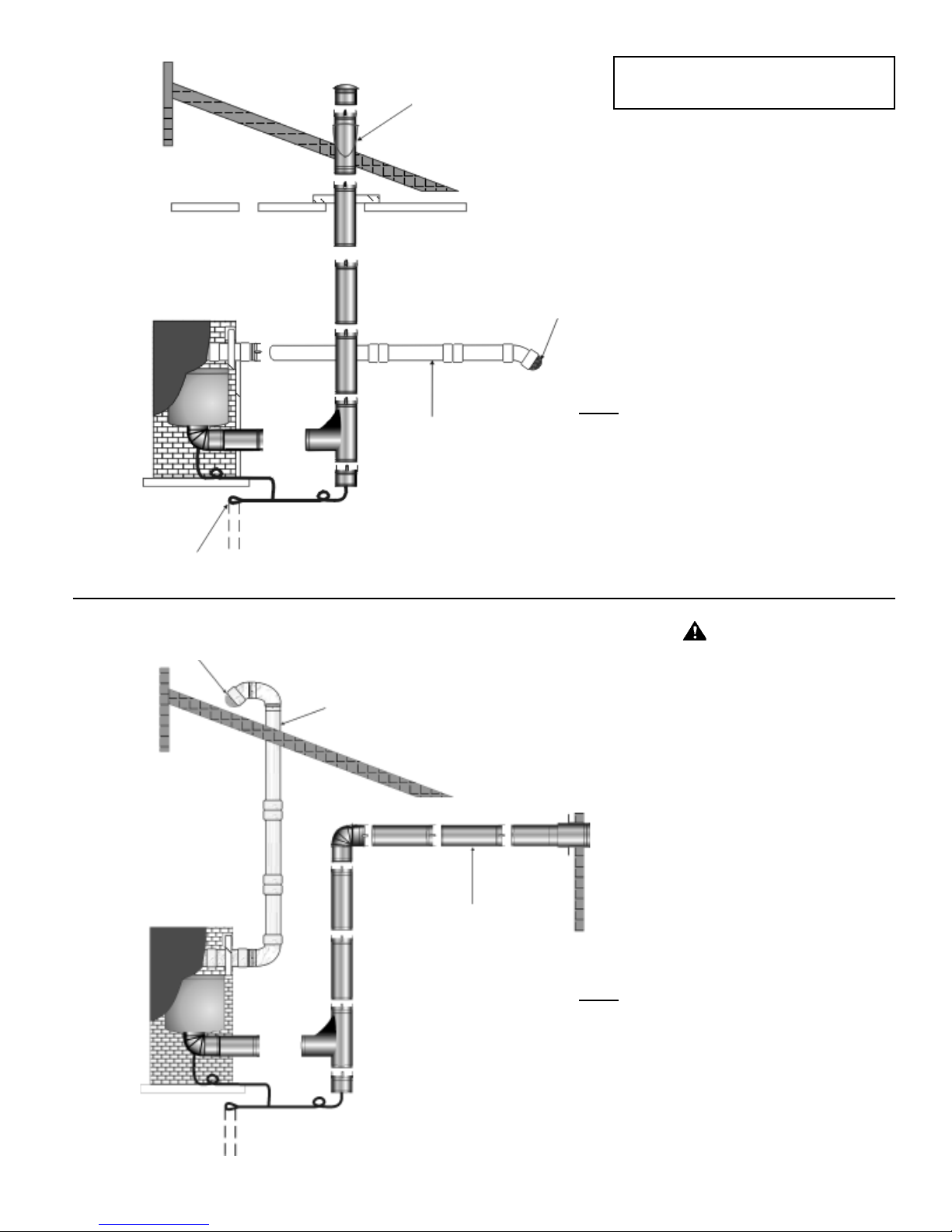
FIGURE 9. VERTICAL TERMINA TION
FIGURE 9A. THROUGH THE WALL TERMINA TION (TWT)
12
Page 13
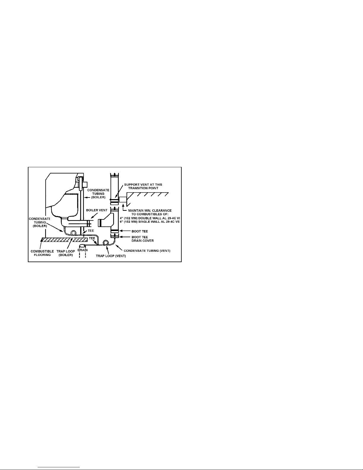
The Boot-Tee Drain Cover is required in order to dispose of
the condensate from the venting system. The plastic tube
(3/8 [9 mm] ID, 10 feet [3 m] long) needed to route the condensate
to a suitable drain is provided with the boiler.
1. Attach the Boot Tee Drain Cover to the appropriate leg of the
Boot-Tee, see figure 10.
DO NOT rivet or screw the straps to the conduit or otherwise
puncture the conduit wall. Instead, wrap an extra loop of strap
around the conduit to hold it in position, or attach the strap to
the center screw of the double wall AL 29-4C
®
vent coupling, if
applicable.
VERTICAL INSTALLATION REQUIREMENTS
2. A trap loop must be formed into the drain tube simply by looping
the tube to a minimum 3 inch (76 mm) diameter and secure
the loop with a cable tie, see figure 10.
3. Prior to final assembly the trap loop must be “primed” by
pouring a small quantity of water into the drain hose.
4. Connect the Boot-Tee and Drain Tee assembly to the boiler
vent connector, see figure 10.
5. Attach the hose to the drain fitting and run the hose to a sanitary
sewer drain maintaining the proper trap loop and following all
local, state and federal codes and regulations for draining of
acidic effluent (condensate).
FIGURE 10.
VENTING SUPPORTS
1. The vent system must terminate at least three (3) feet [1.0 m]
and no more than six (6) feet [2.0 m] above the roof line and no
closer than ten (10 ) feet [3.0 m] from any wall or vertical
structure. If the exhaust vent terminal is within 10’ (3.0 m) of a
wall or parapet, it must extend a minimum of 2’ (610 mm)
above the wall or parapet. See figures 9 and 11A.
2. For direct vent installations, the total distance of the vent system
from the boiler vent connector to the vertical vent termination
shall not exceed ninety (90) equivalent feet [27.4 m]. A
maximum of three (3) 90° elbows can be used. Minimum
vertical vent is nine (9) equivalent feet [2.7 m] for direct vent
installations. For standard installations where no air intake
piping is included, the total distance can be extended to
180 equivalent feet [54.9 m] with a maximum of five (5)
90° degree elbows. Standard minimum vertical vent length is
five (5) feet [1.5 m]. See figures 9, 11A, 11B, and 11C for
differences between standard and direct vent installations.
3. An AL 29-4C
®
Vent Vertical Vent Terminal must be used at the
termination.
4. Maintain a minimum of six (6) feet [2.0 m] separation between
the air intake and the exhaust terminals.
HORIZONTAL INSTALLATION REQUIREMENTS
1. The vent system must terminate with a AL 29-4C® Vent
Through-the-Wall Termination (TWT). Plan the terminal
location based on the dimensions given in figure 8. Do not
locate the terminal within eight (8) feet (2.5 m) of an inside
corner of a building or adjacent to outside walls, shrubs or
other such objects that may cause adverse wind conditions in
the immediate area.
Care must be taken in the installation of the venting system that
adequate support is maintained throughout the installation
process. When extending more than 10 feet (3.0 m) vertically,
vertical support kits are required once every 10 feet (3.0 m) of
vertical run. Vertical support is also required immediately after
any transition (elbow, tee, etc.) to vertical of over 10 feet (3.0 m) of
run and after any offset in the vertical run.
The support bracket (supplied in the Vertical Support Kit) is to be
securely fastened to a solid vertical member of the building using
the appropriate fasteners; i.e., wood screws for wood framing,
machine or tapping screws for structural steel or masonry anchors
for solid masonry. The bracket should be located so that it will
not interfere with any joints of the venting system. The bottom
most support bracket should be located directly above the first
transition from horizontal to vertical, see Figure 10. Refer to figures
11, 11A, 11B and 11C.
If a means of support for the bracket is not available and horizontal
vent sections are present, install hanger straps (made from
non-combustible material) as close to the points of transition as
possible. If the horizontal portions of the vent and/or vent connector
are longer than 6 feet (2.0 m), then install hanger straps every
6 feet (2.0 m) to support the connector.
2. The TWT shall be located not less than 12 inches (305 mm)
above grade or, in geographical areas where snow
accumulates, no less than 12 inches (305 mm) above the
anticipated snow line. Ensure that the TWT is protected
against blockage which may occur during ice buildup or
snowstorms.
The TWT shall terminate at least three (3) feet [1.0 m] above
any forced air inlet within ten (10) feet [3.0 m], except when the
forced air inlet is the combustion air intake of a direct vent
appliance. The TWT shall terminate at least four (4) feet
[1.2 m] below, four (4) feet [1.2 m] horizontally from or one (1)
foot [305 mm] above any door, window or gravity air inlet into
any building as provided in the latest edition of the NATIONAL
FUEL GAS CODE ANSI Z223.1, see figure 8. For Canadian
installations consult CSA B149.1-00 (and latest addenda).
In addition, a minimum clearance of four (4) feet (1.2 m)
horizontally from, and in NO CASE ABOVE OR BELOW, unless
the four (4) feet [1.2 m] of horizontal distance is maintained
from electric meters, gas meters, regulators and relief
equipment.
3. For direct vent installations, the total horizontal distance of the
vent system from the boiler vent connector to the outside of the
13
Page 14

CAUTION
Direct venting into dead air spaces such
as; alleys, atriums and inside corners can
cause recirculation of flue gases.
Recirculation of flue gases will cause
sooting, premature failure of the heat
exchanger and icing of the combustion
air intake during severe cold weather. To
prevent the recirculation of flue gases,
maintain as much distance as possible
between the combustion air intake and
the exhaust vent terminal.
NOTES: If the exhaust vent terminal is
within 10’ (3.0 M) of a wall or parapet, it
must extend a minimum of 2’ (610 MM)
above the wall or parapet.
NOTE: Joints are not joined to
show vent pipe orientation.
FIGURE 11. DIRECT VENT HORIZONT AL
Joints are not joined to show vent pipe
orientation.
FIGURE 11A. DIRECT VENT VERTICAL
14
Page 15
90 EQUIVALENT FEET (27.4M)
OF VENTING (MAX.) AL 29-4C
HORIZONTA L AIR INTAKE
PVC PIPE 90
EQUIVALENT FEET (27.4M)
Option B (Figures 11B & 1 1C)
assures no recirculation of flue gases.
AIR INTAKE TERMINAL
NOTES:
• IF THE EXHAUST VENT TERMINAL IS WITHIN 10’ (3.0M)
OF A W ALL OR A PARAP ET, IT MIUST EXTEND A MINIMUM
OF 2’ (0.6M) ABOVE THE W ALL OR P ARA PET.
• ON SIDEWALL VENT INST ALLATION, REFER
TO FIGURE 7 FOR SPACING SPECIFICATIONS
• FOR EXHAUST AND AIR INTAKE PIPE INSTALLATIONS
(CLEARANCES, SUPPORT, ETC.) REFER TO FIGURES
11 AND 11A.
FIGURE 11B. DIRECT VENT , VERTICAL VENT TERMINA TION WITH HORIZONT AL INT AKE
VERTICAL AIR INT AKE MUST BE
12” (305mm) ABOVE ANTICIP ATED
SNOW LEVEL.
PVC PIPE 90 EQUIVALENT FEET (27.4M)
90 EQUIVALENT FEET (27.4M)
OF VENTING (MAX.) AL 29-4C
CAUTION
Direct venting into dead air spaces such as; alleys,
atriums and inside corners can cause recirculation of
flue gases. Recirculation of flue gases will cause
sooting, premature failure of the heat exchanger and
icing of the combustion air intake during severe cold
weather. To prevent the recirculation of flue gases,
maintain as much distance as possible between the
combustion air intake and the exhaust vent terminal.
NOTES:
• IF THE EXHAUST VENT TERMINAL IS WITHIN 10’ (3.0M)
OF A W ALL OR A PARAP ET, IT MIUST EXTEND A MINIMUM
OF 2’ (0.6M) ABOVE THE W ALL OR P ARA PET.
• ON SIDEWALL VENT INST ALLATION, REFER
TO FIGURE 8 FOR SPACING SPECIFICATIONS
• FOR EXHAUST AND AIR INTAKE PIPE INSTALLATIONS
(CLEARANCES, SUPPORT, ETC.) REFER TO FIGURES
11 AND 11A.
FIGURE 11C. DIRECT VENT USING TWT WITH VERTICAL INTAKE
15
Page 16

TWT shall not be greater than ninety (90) equivalent feet
[27.4 m] of vent pipe nor less than nine (9) feet [3 m] (excluding
fittings) unless the vent is through a non-combustible wall. A
maximum of three (3) 90° degree elbows may be used. For
standard installations where no air intake piping is included,
the total distance can be extended to 180 equivalent feet
[54.9 m] with a maximum of five (5) 90° degree elbows.
Standard minimum horizontal vent length is three (3) feet
[1.0 m]. See figures 9A and 1 1 for differences between st andard
and direct vent installations.
4. This horizontal exhaust vent system must pitch upward toward
the termination at 1/4 inch per foot (21 mm per meter).
5. The TWT is designed such that the building is protected from
degradation by flue gas and condensate. However, if
additional protection is desired, install against the wall a
non-corrosive metal sheet under the TWT.
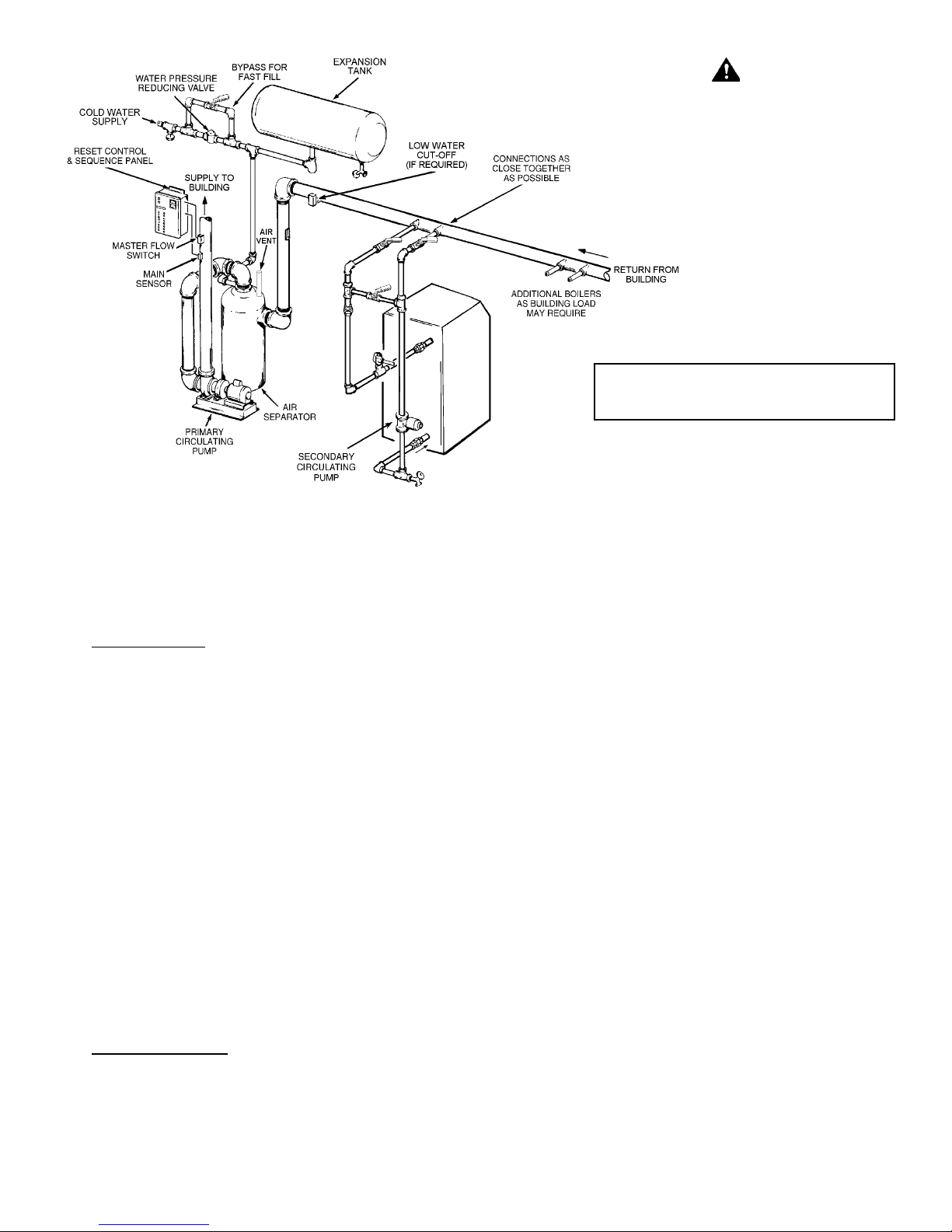
Figure 12 shows a typical primary, secondary piping method.
This is the preferred piping method for most copper fin tube
boilers. Other piping methods, however, may provide good system
operation. A prime concern when designing heating systems is
the maintenance of proper flow through the unit during boiler
operation. The secondary pump should be sized per the
recommended flow rate of the boiler. (See recommended flow
charts on pages 2 and 3 of this manual.)
A system bypass should be installed as shown in fig. 12 to prevent
boiler circulation starvation when the system zones call for
reduced flow.
This bypass may also be used with multiple boilers manifolded
for reverse-return flow. This system bypass would be installed
from boiler outlet to suction side of pump.
HOT WATER HEATING (HYDRONIC) EQUIPMENT
6. Due to the normal formation of water vapor in the combustion
process, horizontal terminations must not be located over areas
of pedestrian or vehicular traffic, (i.e., public walkways or over
areas where condensate could create a nuisance or hazard).
This is especially true in colder climates where ice buildup is
likely to occur. A.O. Smith Corporation will not be held liable
for any personal injury or property damage due to any
dislodging of ice.
DIRECT VENT INSTALLATION REQUIREMENTS
Follow the guidelines in the “HORIZONTAL INSTALLATION
REQUIREMENTS” section for the exhausting of flue products.
IMPORTANT
The labels in the Direct Vent Kit must be affixed to the boiler in
locations specified by the instruction sheet provided in the kit.
The following are requirements for the Air-Intake Terminal (AIT):
1. The Air-Intake System (AIS) must terminate with the venting
equipment provided with the boiler, see “DIRECT VENT KIT
PAR TS LIST”, part no. 192109.
2. The AIT shall not be located less than three (3) feet [1.0 m]
below any exhaust vent within ten (10) feet [3.0 m], also see
“HORIZONTAL INST ALLA TION REQUIREMENTS” section.
3. The total horizontal distance of the AIS from the boiler’s Blower
Adapter to the outside of the “AIT” shall not be greater than
ninety (90) “equivalent” feet [27.4 m] of vent pipe nor less than
three (3) feet [1.0 m] (excluding elbows). A maximum of three
(3) elbows, equivalent to ten (10) feet (3.0 m) of pipe each may
be used.
SYSTEM INST ALLA TION
GENERAL
If the system is to be filled with water for testing or other purposes
during cold weather and before actual operation, care must be
taken to prevent a downdraft entering the boiler or freezing air
from contacting the system. Failure to do so may cause the water
in the system to freeze with resulting damage to the system.
Damage due to freezing is not covered by the warranty.
Good practice requires that all heavy piping, etc., be supported.
The following is a brief description of the equipment required for
the installations noted in this manual. All installations must
comply with local code.
1.
WATER SUPPLY LINE
These boilers can be used ONLY in a forced circulation hot
water heating system. Since most forced circulation systems
will be of the closed type, install the water supply line as shown
on piping diagram, figure 12.
Fast filling of large pipe, old radiator installations and pressure
purging of series loop systems (where high pressures are
not available) requires bypassing of the pressure reducing
valve.
Generally, pressure purging is not possible with a well pump
system. High point air venting is essential.
If the system is of the open type, a pressure reducing valve will
not be required as the water supply to the system will be
controlled by a manually operated valve. An overhead surge
tank is required. A minimum pressure of 15 psi (100 kPa)
must be maintained on the boiler at all times to ensure
avoidance of potential damage to the boiler which may not be
covered by the warranty .
EXPANSION TANK
2.
If the system is of the closed type, install an expansion tank as
shown in figure 12. The sizing of the expansion tank for a
closed system is very important and is directly related to the
total water volume of the system. Refer to “Systems and
Equipment” volume of the ASHRAE handbook.
An air separator as shown in the piping diagrams is
recommended especially for modern commercial hydronic
systems.
VENT VALVES
3.
It is recommended that automatic, loose key or screw-driver
type vent valves be installed at each convector or radiator.
4. SYSTEM HEADERS
Split systems with individual supply and return lines from the
boiler room should normally have this piping connected to
supply and return manifold headers near the boiler. To achieve
good water distribution with maximum pressure drop for
several circuits, manifolds should be larger than system
mains.
The circuits should be spaced on the heater at a minimum of
3” (76 mm) center to center. Install a balancing cock in each
return line.
16
Page 17
TEMPERATURE SETTING SHOULD NOT EXCEED
SAFE USE TEMPERATURE AT FIXTURES. SEE
WA TER TEMPERA TURE CONTROL W ARNING ON
PAGE 28. IF HIGHER PREHEA T TEMPERA TURES
ARE NECESSARY TO OBTAIN ADEQUATE
BOOSTER OUTPUT, ADD AN ANTI-SCALD VAL VE
FOR HOT WA TER SUPPLIED TO FIXTURES.
• INSTALL IN ACCORDANCE WITH ALL LOCAL CODES.
• WHEN BLOW DOWN VALVE IS REQUIRED, INSTALL
IN PLACE OF THE DRAIN VALVE SHOWN.
FIGURE 12. TYPICAL PRIMARY, SECONDARY PIPING
DANGER
Manifold headers are recommended for split systems with or
without zone values and also those installations with zone
circulators. If the system is to be split at remote points, good
practice requires special attention be given to main pipe sizing
to allow balancing of water flow.
5.
COOLING PIPING
When the boiler is used in conjunction with a refrigeration
system it must be installed so that the chilled medium is piped
in parallel with the boiler. Appropriate flow control valves,
manual or motorized, must be provided to prevent the chilled
medium from entering the boiler.
Water temperature in the heating system must be reduced to
less than 100°F (38°C) before cooling system is started, or
damage to the chiller unit may occur.
If the boiler is connected to chilled water piping or its heating
coils are exposed to refrigerated air, the boiler piping system
must be equipped with flow valves or other automatic means
to prevent gravity circulation through the boiler during the
cooling cycle.
Primary/secondary pumping of both the chiller(s) and the
boiler(s) is an excellent winter-summer change-over method,
because cooling flow rates are so much more than heating
flow rates. In this way each system (heating or cooling) is
circulated independently.
6.
CIRCULATING PUMP
FOR HOT WATER HEATING SYSTEMS - LB MODELS, the
circulating pump is NOT provided and must be field-installed.
NOTE: If a system pump is to be installed on a Legend LB
model, the maximum rating of the pump motor must not
exceed 1 hp.
INTERNAL CONTAMINANTS
The hydronic system must be internally cleaned and flushed after
a new or replacement boiler has been installed, to remove
contaminants that may have accumulated during installation. This
is doubly important when a replacement boiler is installed into
an existing system where Stop Leak or other boiler additives
have been used.
Failure to clean and flush the system can produce acid
concentrations that become corrosive, cause gases to form that
block water circulation or lead to formation of deposits on the
boiler surfaces, any of which could result in damage to the system
and circulator.
All hot water heating systems should be completely flushed with
a grease removing solution to assure trouble-free operation. Pipe
joint compounds, soldering paste, grease on tubing and pipe all
tend to contaminate a system
Failure to flush contaminants from a system can cause solids to
form on the inside of boiler exchangers, create excessive amounts
of air and other gases to block circulation, foul various system
accessories and even deteriorate circulation seals and impellers.
HOT WATER SUPPLY BOILER SYSTEM-
GENERAL WATER LINE CONNECTIONS
This section provides detailed installation diagrams for a typical
method of application for the unit.
Piping diagrams will serve to provide the installer with a reference
for the materials and methods of piping necessary for installation.
It is essential that all water piping be installed and connected as
shown on the diagrams. Check the diagrams to be used
thoroughly before starting installation to avoid possible errors
and to minimize time and material cost.
It is essential that all water piping be installed and connected as
shown on the diagrams. Check the diagrams to be used
thoroughly before starting installation to avoid possible errors
and to minimize the time and material cost.
17
Page 18
ONE LEGEND (MODEL LW) HOT WATER SUPPLY BOILER WITH VERTICAL TANK
INSTALL THERMAL EXPANSION
TANK ON COLD WATER SUPPL Y
LINE, IF CHECK VALVE OR
PRESSURE REDUCING VA L VE IS
USED IN SUPPLY.
DANGER
TEMPERATURE SETTING SHOULD NOT EXCEED SAFE USE
TEMPERATURE A T FIXTURES. SEE WA TER TEMPERA TURE
CONTROL WARNING ON PAGE 28. IF HIGHER PREHEAT
TEMPERATURES ARE NECESSARY TO OBTAIN ADEQUA TE
BOOSTER OUTPUT , ADD AN ANTI-SCALD V AL VE FOR HOT
WA TER SUPPLIED TO FIXTURES.
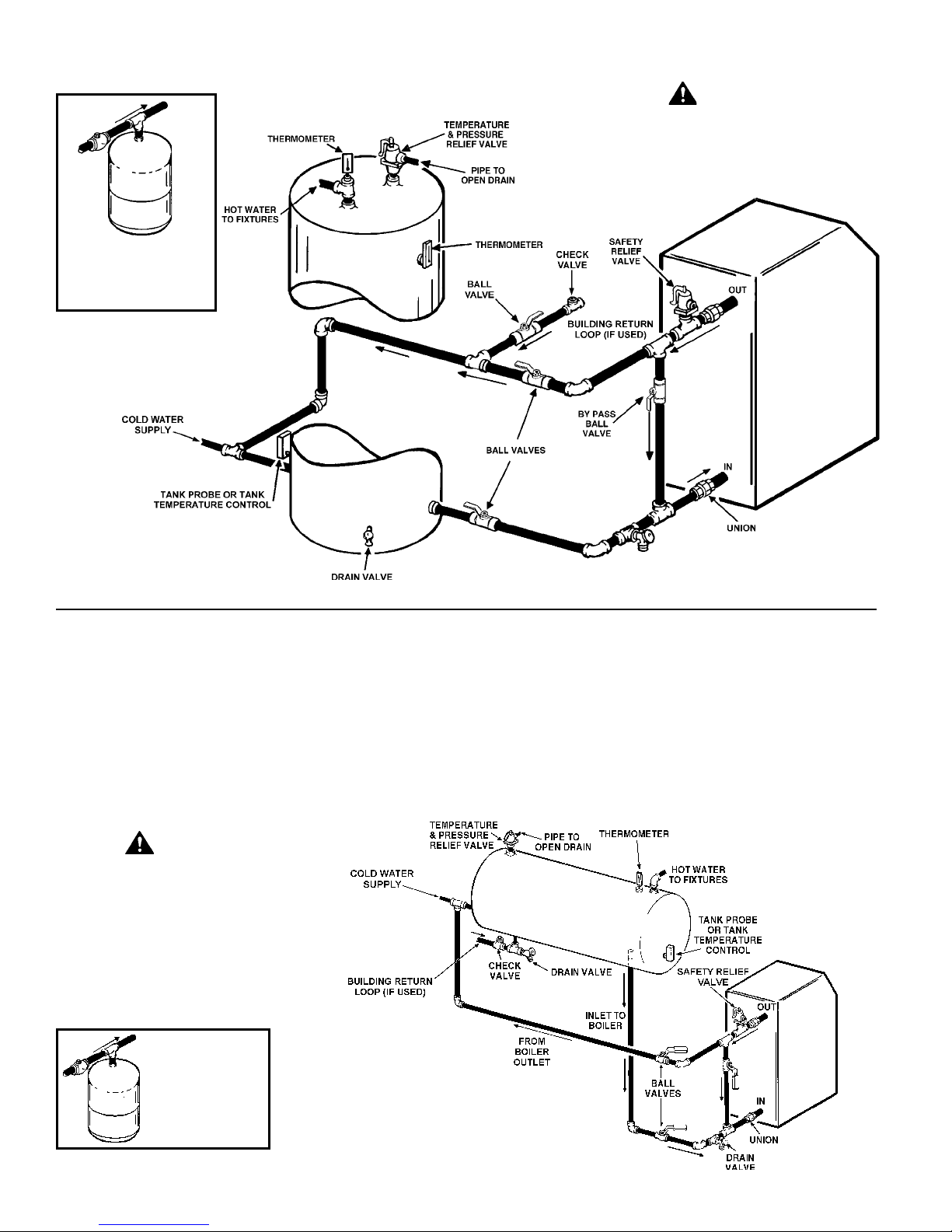
FIGURE 13.
ONE LEGEND (MODEL LW) HOT WATER SUPPLY BOILER WITH HORIZONTAL TANK
INSTALL IN ACCORDANCE WITH ALL LOCAL CODES.
PRESSURE RELIEF VAL VE RA TING SHOULD NOT EXCEED PRESSURE
CAPACITY OF ANY COMPONENT IN THE SYSTEM.
INSTALL TEMPERA TURE, PRESSURE GAUGE AND PRESSURE RELIEF AS
CLOSE TO BOILER OUTLET AS POSSIBLE.
SHUTOFF V AL VES SHOULD BE INST ALLED FOR SERVICING BOILER,
LOCAL CODES SHALL GOVERN THEIR USAGE.
DANGER
TEMPERA TURE SETTING SHOULD NOT
EXCEED SAFE USE TEMPERATURE A T
FIXTURES. SEE WA TER TEMPERA TURE
CONTROL WARNING ON PAGE 28. IF
HIGHER PREHEA T TEMP-ERATURES ARE
NECESSARY TO OBTAIN ADEQUATE
BOOSTER OUTPUT, ADD AN ANTISCALD VALVE FOR HOT WATER
SUPPLIED TO FIXTURES.
SAFETY RELIEF V ALVE SETTING SHOULD NOT EXCEED PRESSURE
RATING OF ANY COMPONENT IN THE SYSTEM.
STOP V AL VES ARE SHOWN FOR SERVICING BOILER. HOWEVER, LOCAL
CODES SHALL GOVERN THEIR USAGE.
CAUTION: IF BUILDING COLD WATER SUPPLY HAS A BACKFLOW
PREVENTER CHECK VAL VE OR W A TER METER WITH CHECK V AL VE,
PROVISIONS FOR THERMAL EXP ANSION OF WA TER IN THE HOT W A TER
SYSTEM MUST BE PROVIDED.
INSTALL THERMAL
EXPANSION TANK ON
COLD WATER SUPPLY
LINE, IF CHECK VA L VE
OR PRESSURE
REDUCING VA L VE IS
USED IN SUPPLY .
FIGURE 14.
18
Page 19

HARD WATER CONDITIONS
TANK PROBE SET-POINT ADJUSTMENT
Where hard water conditions exist, water softening or the threshold
type of water treatment is recommended. This will protect the
dishwashers, coffee urns, water heaters, water piping and other
equipment. When water softening or water treatment is not
practical, a comparatively easy method of periodic lime removal
from the unit may be employed.
PRESSURE RELIEF VALVE RATING SHOULD NOT EXCEED
PRESSURE CAPACITY OF ANY COMPONENT IN THE SYSTEM.
INSTALL TEMPERA TURE, PRESSURE GAUGE AND PRESSURE
RELIEF AS CLOSE TO BOILER OUTLET AS POSSIBLE.
SHUTOFF VA LVES SHOULD BE INSTALLED FOR SERVICING
BOILER, HOWEVER, LOCAL CODES SHALL GOVERN THEIR
USAGE.
THERMAL EXPANSION (CLOSED SYSTEM)
Thermal expansion occurs in any hot water system when system
water is heated or “recovered” during periods of non-use.
If the system is operated in an “open” condition such as being
connected directly to the city main, the volume of expanded water
generated during the recovery periods can be dissipated back
through the “open” connection to the city main so pressure cannot
build up.
However, once a back flow preventer is installed to isolate system
water from the public supply; or a pressure reducing valve is
installed to protect a water meter; or any device preventing flow
back into the cold water supply, the “open” condition becomes
“closed”. During periods of temperature recovery and no usage,
expanded water has no place to go, so the pressure builds up
until a relief valve opens releasing hot water.
A relief valve opening on pressure will flow small amounts of
water, whereas relieving on temperature releases large amounts
of water.
If your system is closed, some provision must be made for
THERMAL EXPANSION to protect the system from excessive
pressure. Install an expansion tank that is properly and adequately
sized for the expanding volume of water in the system.
Service problems or parts failure due to excessive pressure are
NOT covered under warranty.
TANK PROBE INSTALLATION PROCEDURE
A tank probe system temperature sensor is supplied with each
hot water supply boiler (LW models). When installed on a tank,
the inlet water temperature on the Dia-Scan II will default to the
tank temperature. See figure 21 and 22 for position of tank
probe jumper. As stated earlier, if one wishes to use an
alternative method of temperature control, this jumper must
be removed.
The tank probe sensor wires are run from the plug on the control
board to the junction box at the rear of the unit. Field wiring (in
conduit) is required from the plug wires to the tank probe sensor wires.
See figure 7.
When the temperature sensor is installed in a water tank, and
the sensor is used with the WHC1502 system, the controller will
monitor and control the temperature of the water at the sensor
location. Setting the temperature is accomplished through the
Dia-Scan II control display . The programmable temperature range
is 110°F to 190°F (43°C to 88°C). The switching differential is
fixed at 5°F (3°C).
GAS CONNECTIONS
CAUTION
MAKE SURE THE GAS ON WHICH THE BOILER IS TO OPERA TE IS
THE SAME AS THA T SPECIFIED ON THE RATING PLA TE. DO NOT
INST ALL THE BOILER IF EQUIPPED FOR A DIFFERENT TYPE OF
GAS. CONSUL T YOUR GAS SUPPLIER.
THIS BOILER IS NOT INTENDED TO OPERA TE A T GAS SUPPL Y
PRESSURE OTHER THAN SHOWN ON THE RA TING PLA TE. A
LOCK-UP OR POSITIVE SHUT -OFF TYPE REGULAT OR MUST BE
INSTALLED IN THE GAS SUPPL Y LINE. EXPOSURE TO HIGHER
GAS SUPPL Y PRESSURE MA Y CAUSE DAMAGE TO GAS V ALVES
WHICH CAN RESULT IN FIRE OR EXPLOSION. IF OVERPRESSURE
HAS OCCURRED SUCH AS THROUGH IMPROPER TESTING OF
GAS LINES OR EMERGENCY MALFUNCTION OF THE SUPPL Y
SYSTEM, THE GAS VALVES MUST BE CHECKED FOR SAFE
OPERATION. MAKE SURE THA T THE OUTSIDE VENTS ON THE
SUPPL Y REGULA TORS AND THE SAFETY VENT V AL VES ARE
PROTECTED AGAINST BLOCKAGE. THESE ARE PARTS OF THE
GAS SUPPL Y SYSTEM, NOT THE BOILER. VENT BLOCKAGE MA Y
OCCUR DURING ICE BUILD-UP OR SNOWSTORMS.
THE BOILER MUST BE ISOLATED FROM THE GAS SUPPLY
PIPING SYSTEM BY CLOSING ITS MAIN MANUAL GAS
SHUT-OFF V AL VE DURING ANY PRESSURE TESTING OF THE GAS
SUPPL Y PIPING SYSTEM A T TEST PRESSURES EQUAL TO OR
LESS THAN 1/2 PSIG .
DISCONNECT THE BOILER AND ITS MAIN MANUAL GAS SHUT OFF VALVE FROM THE GAS SUPPLY PIPING DURING ANY
PRESSURE TESTING OF THE GAS SUPPLY SYSTEM OVER
1/2 PSIG . THE GAS SUPPL Y LINE MUST BE CAPPED WHEN NOT
CONNECTED TO THE BOILER.
IT IS IMPORTANT T O GUARD AGAINST GAS V AL VE FOULING
FROM CONTAMINANTS IN THE GAS W A YS. SUCH FOULING MA Y
CAUSE IMPROPER OPERATION, FIRE OR EXPLOSION. IF COPPER
SUPPL Y LINES ARE USED THEY MUST BE APPROVED FOR GAS
SERVICE.
WHEN LOCAL CODES REQUIRE A MAIN MANUAL SHUT-OFF
VALVE OUTSIDE THE BOILER JACKET, A SUITABLE MAIN
MANUAL SHUT -OFF VAL VE MUST BE INST ALLED IN A LOCA TION
COMPLYING WITH THOSE CODES.
BEFORE ATTACHING THE GAS LINE BE SURE THAT ALL GAS
PIPE IS CLEAN ON THE INSIDE.
TO TRAP ANY DIRT OR FOREIGN MATERIAL IN THE GAS
SUPPLY LINE, A DIRT LEG (SOMETIMES CALLED DRIP LEG)
MUST BE INCORPORATED IN THE PIPING. THE DIRT LEG
MUST BE READILY ACCESSIBLE AND NOT SUBJECT TO
FREEZING CONDITIONS. INSTALL IN ACCORDANCE WITH
RECOMMENDA TIONS OF SERVING GAS SUPPLIER. REFER TO
NATIONAL FUEL GAS CODE, ANSI Z223.1 OR CAN/CSA – B149.100 (AND LATEST ADDENDA).
19
Page 20
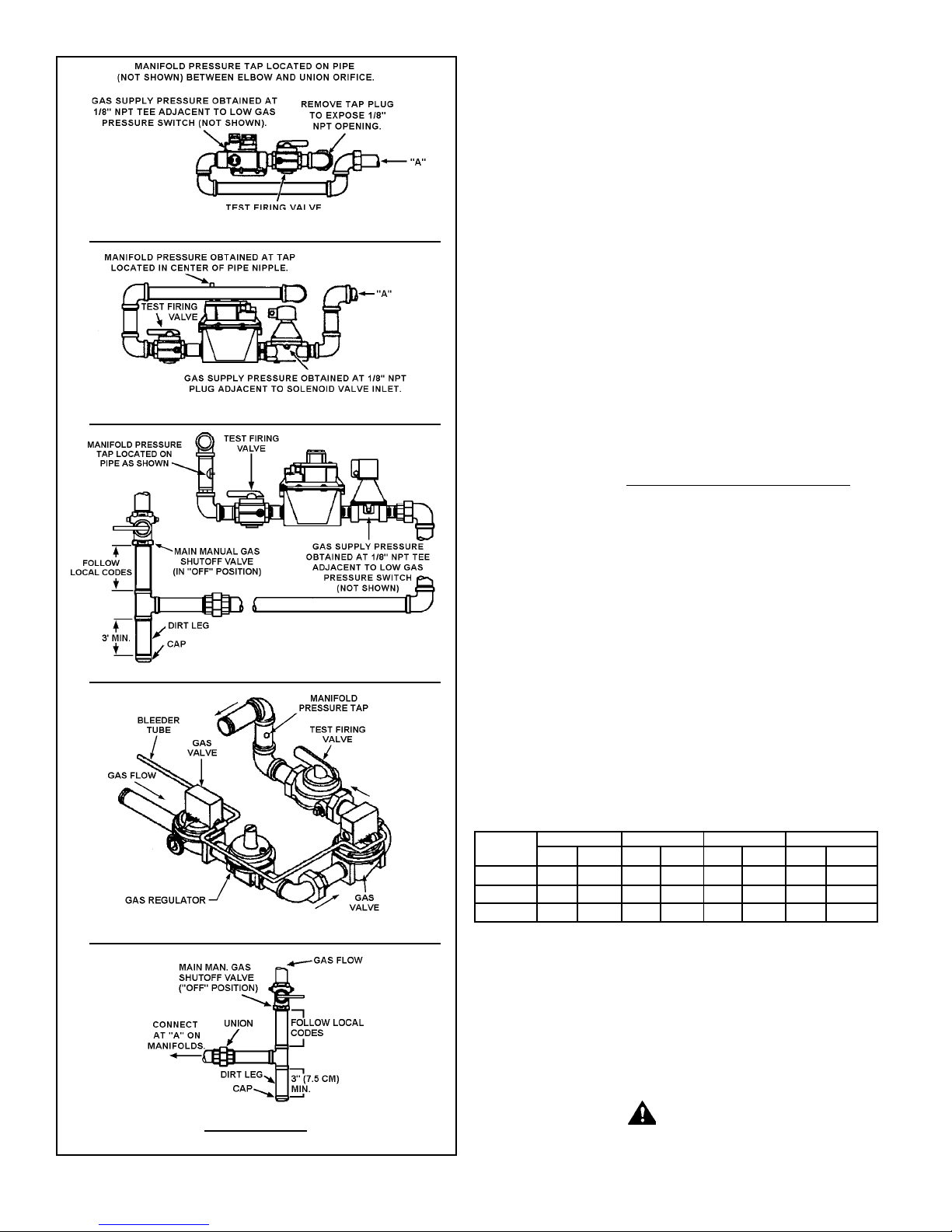
LB/LW-500 NATURAL & PROPANE GAS
LB/LW-750 NATURAL GAS
Size of gas supply piping may be larger than heater connection
on installations where a significant run of piping is required.
To prevent damage, care must be taken not to apply too much
torque when attaching gas supply pipe to boiler gas inlet.
Fittings and unions in the gas line must be of the metal to metal type.
Apply joint compounds (pipe dope) sparingly and only to the male
threads of pipe joints. Do not apply compound to the first two
threads. Use compounds resistant to the action of liquefied
petroleum gases.
GAS SUPPL Y LINE SIZING
The gas piping installation must be capable of supplying the
maximum probable gas demand without excessive pressure
loss. Depending on local practices, the ALLOW ABLE PRESSURE
LOSS between the gas meter, or service regulator and each
appliance is generally 0.3 or 0.5 inches of water column
( 0.075 or 0.124 kPa).
For single boiler installation, refer to table 6 to size iron pipe or
equivalent gas supply line size to be used with single unit.
For multiple boiler installation or installations of a single boiler
with other gas appliances please refer to tables 7 and 8 to size
iron pipe or equivalent gas supply line. These tables are taken
from ANSI Z223.1
NATIONAL FUEL GAS CODE, or
CAN/CSA – B149.1 - 00 (and latest addenda):
LB/LW - 1000 NATURAL GAS
LB/LW - 750 & 1000 PROPANE GAS
• Table 7 is based on a pressure drop of 0.5 inches water
column (0.124 kPa), and a gas with a specific gravity of 0.60
and a heating value of 1,000 BTU/ft3, approximately that of
Natural Gas.
• Table 8 is based on a pressure drop of 0.5 inches water
column (0.124 kPa), and a gas with a specific gravity of 1.53
and a heating value of 2,500 BTU/ft
3
, approximately that of
Propane Gas.
No additional allowance is necessary for an ordinary number of
fittings. Where it is necessary to use more than the average
number of fittings (i.e., elbows, tees and valves in gas supply
line) use a pipe larger than specified to compensate for increased
pressure drop.
TABLE 6.
SINGLE UNIT INSTALLATION, SUGGESTED GAS PIPE SIZING.
MAXIMUM EQUIVALENT PIPE LENGTH (IN FEET).
Btu 1-1/4" 1-1/2" 2" 2-1/2"
Input Nat. Prop. Nat. Prop. Nat. Prop. Nat. Prop.
500,000 40 90 80 200 — — — —
750,000 10 40 40 90 125 — — —
1,000,000 —- 20 20 50 70 175 175 —
Natural gas 1000 Btu/ft^3, 0.60 specific gravity @ 0.3 in. w.c. pressure drop
Propane gas 2500 Btu/ft^3, 1.50 specific gravity @ 0.3 in. w.c. pressure drop.
MAIN MANUAL GAS SHUT-OFF VALVE, DRIP LEG & UNION
FIELD INSTALLED
Table 6 shows the maximum equivalent gas pipe length for a
single unit installation. It does not take into account other
appliances that may be connected to the gas line. For installation
of multiple units, or instances where several appliances are
connected to the same line, use tables 7 and 8 for proper sizing.
WIRING
CAUTION
LABEL ALL WIRES PRIOR TO DISCONNECTION WHEN
SERVICING CONTROLS. WIRING ERRORS CAN CAUSE
IMPROPER AND DANGEROUS OPERA TION.FIGURE 15. GAS MANIFOLDS
20
Page 21
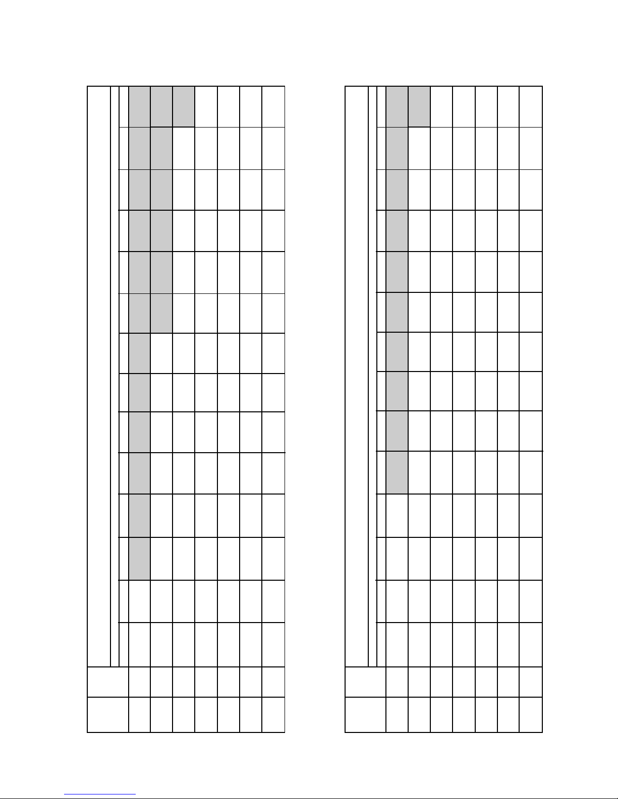
kW 199 136 — — — — — — — — — — — —
kW 410 278 226 193 170 155 144 135 — — — — — —
kW 615 428 346 290 264 237 220 202 190 182 161 146 135 —
kW 1,157 805 644 556 492 445 410 381 357 337 299 278 249 234
kW 1,845 1,274 1,031 879 776 703 659 600 571 542 483 439 401 375
kW 3,222 2,255 1,830 1,552 1,391 1,259 1,142 1,084 1,010 952 864 776 718 668
kW 6,736 4,627 3,749 3,192 2,841 2,577 2,372 2,197 2,109 1,962 1,757 1,611 1,464 1,347
kW 311 212 171 146 — — — — — — — — — —
kW 640 434 352 302 265 242 224 210 196 183 164 148 137 —
kW 959 667 539 452 411 370 343 315 297 283 251 228 210 196
kW 1,805 1,256 1,005 868 768 694 640 594 557 525 466 434 388 366
kW 2,878 1,987 1,608 1,371 1,211 1,097 1,028 937 891 845 754 685 626 585
kW 5,026 3,518 2,856 2,421 2,170 1,965 1,782 1,690 1,576 1,485 1,348 1,211 1,119 1,042
kW 10,508 7,219 5,848 4,980 4,432 4,021 3,701 3,427 3,290 3,061 2,741 2,513 2,284 2,102
1 BTU/hr 680,000 465,000 — — — — — — — — — — — —
Size Length of Pipe in Feet (Meters)
Nominal Maximum Capacity of Pipe in BTU/hr and kW for Gas Pressures of 14 in. W.C. (0.5 psi) or Less and
(Inches) 10 (3.05) 20 (6.1) 30 (9.14) 40 (12.19) 50 (15.24) 60 (18.29) 70 (21.34) 80 (24.38)90 (27.43) 100 (30.48) 125 (38.1) 1 50 175 2 00
Iron Pipe a Pressure Drop of 0.5 in. W.C. (based on 0.60 Specific Gravity Gas w/Heating Value of 1,000 BTU's/Ft3)
T able 7. Suggested Pipe Size For Multiple Gas Appliances (Natural Gas).
1 1/4 BTU/hr 1,400,000 950,000 770,000 660,000 580,000 530,000 490,000 460,000 — — — — — —
1 1/2 BTU/hr 2,100,000 1,460,000 1,180,000 990,000 900,000 810,000 750,000 690,000 650,000 620,000 550,000 500,000 460,000 —
2 BTU/hr 3,950,000 2,750,000 2,200,000 1,900,000 1,680,000 1,520,000 1,400,000 1,300,000 1,220,000 1,150,000 1,020,000 950,000 850,000 800,000
3 BTU/hr 11,000,000 7,700,000 6,250,000 5,300,000 4,750,000 4,300,000 3,900,000 3,700,000 3,450,000 3,250,000 2,950,000 2,650,000 2,450,000 2,280,000
2 1/2 BTU/hr 6,300,000 4,350,000 3,520,000 3,000,000 2,650,000 2,400,000 2,250,000 2,050,000 1,950,000 1,850,000 1,650,000 1,500,000 1,370,000 1,280,000
4 BTU/hr 23,000,000 15,800,000 12,800,000 10,900,000 9,700,000 8,800,000 8,100,000 7,500,000 7,200,000 6,700,000 6,000,000 5,500,000 5,000,000 4,600,000
21
1 BTU/hr 1,060,800 725,400 585,000 499,200 — — — — — — — — — —
Size Length of Pipe in Feet (Meters)
Nominal Maximum Capacity of Pipe in BTU/hr and kW for Gas Pressures of 14 in. W.C. (0.5 psi) or Less and
(Inches) 10 (3.05) 20 (6.1) 30 (9.14) 40 (12.19) 50 (15.24) 60 (18.29) 70 (21.34) 80 (24.38)90 (27.43) 100 (30.48) 125 (38.1) 1 50 175 2 00
Iron Pipe a Pressure Drop of 0.5 in. W.C. (based on 0.60 Specific Gravity Gas w/Heating Value of 1,000 BTU's/Ft3)
T able 8. Suggested Pipe Size For Multiple Gas Appliances (Propane Gas).
1 1/4 BTU/hr 2,184,000 1,482,000 1,201,200 1,029,600 904,800 826,800 764,400 717,600 670,800 624,000 561,600 507,000 468,000 —
1 1/2 BTU/hr 3,276,000 2,277,600 1,840,800 1,544,400 1,404,000 1,263,600 1,170,000 1,076,400 1,014,000 967,200 858,000 780,000 717,600 670,800
2 BTU/hr 6,162,000 4,290,000 3,432,000 2,964,000 2,620,800 2,371,200 2,184,000 2,028,000 1,903,200 1,794,000 1,591,200 1,482,000 1,326,000 1,248,000
2 1/2 BTU/hr 9,828,000 6,786,000 5,491,200 4,680,000 4,134,000 3,744,000 3,510,000 3,198,000 3,042,000 2,886,000 2,574,000 2,340,000 2,137,200 1,999,800
3 BTU/hr 17,160,000 12,012,000 9,750,000 8,268,000 7,410,000 6,708,000 6,084,000 5,772,000 5,382,000 5,070,000 4,602,000 4,134,000 3,822,000 3,556,800
4 BTU/hr 35,880,000 24,648,000 19,968,000 17,004,000 15,132,000 13,728,00012,636,00011,700,00011,232,00010,452,0009,360,000 8,580,000 7,800,000 7,176,000
Page 22
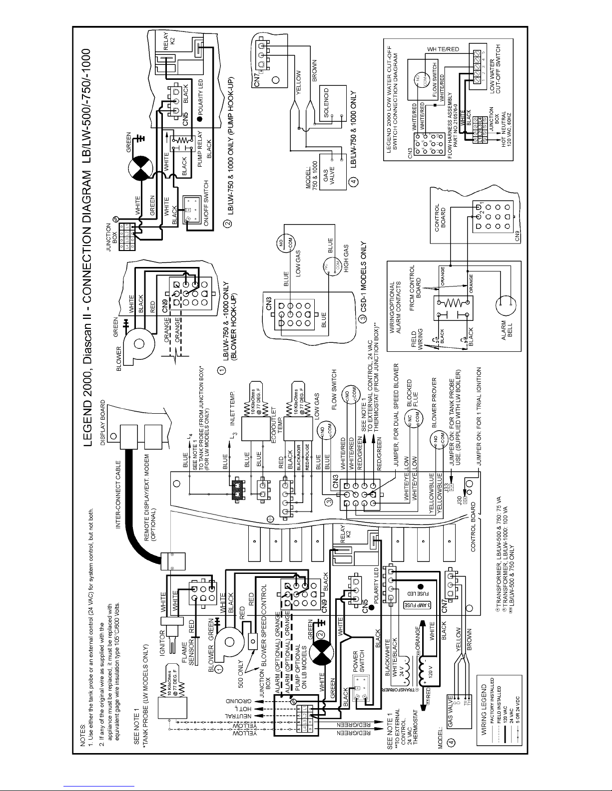
FIGURE 16. CONNECTION DIAGRAM
22
Page 23
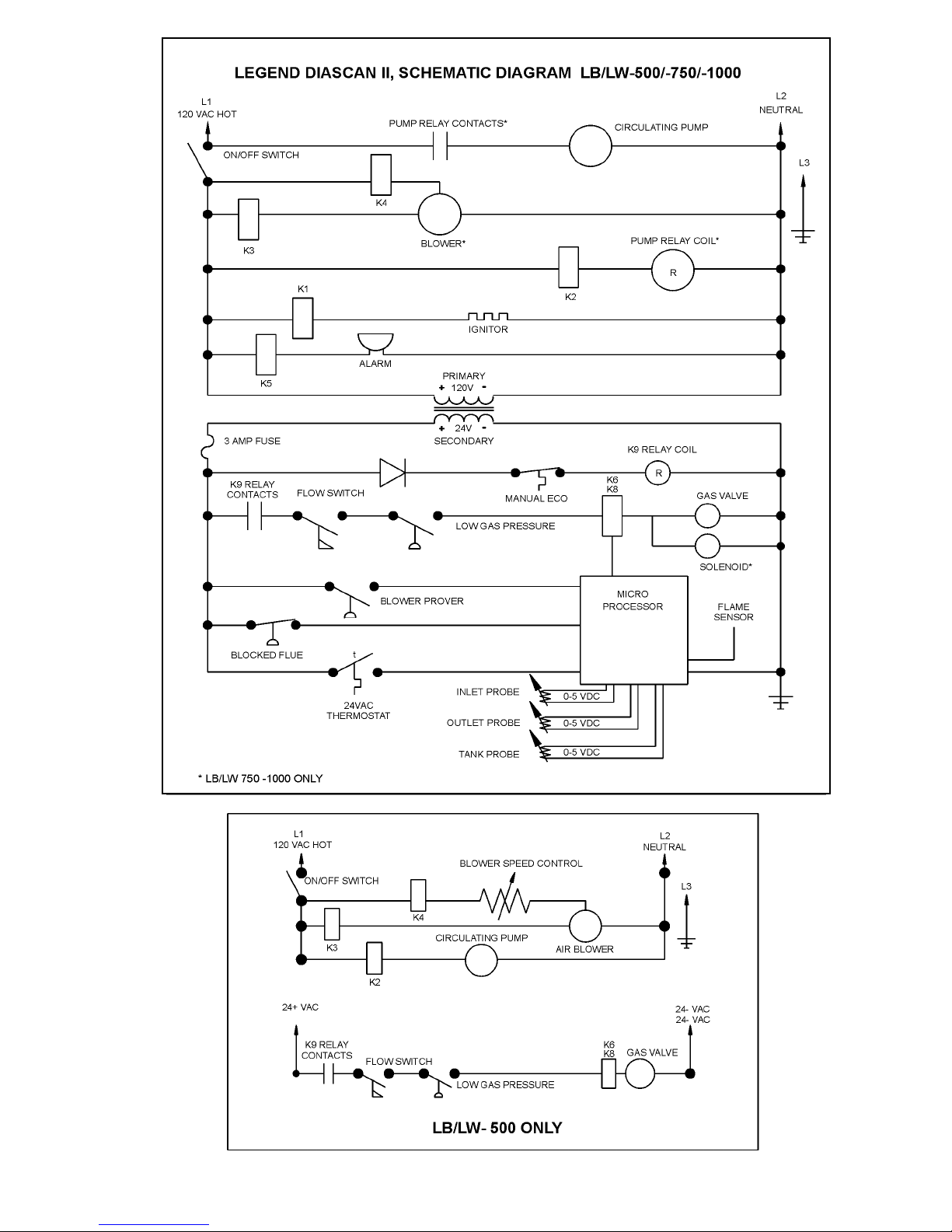
FIGURE 17 - SCHEMATIC DIAGRAM
23
Page 24

VERIFY PROPER OPERATION AFTER SERVICING. STRICT
ADHERENCE TO THE WIRING DIAGRAMS IS REQUIRED TO
PREVENT CONST ANT PUMP OPERA TION WHEN THE SYSTEM
CONTROLLER IS SATISFIED. OTHERWISE THE WARRANTY IS
VOID AS STIPULATED IN THE LIMITED WARRANTY IN THIS
INSTALLA TION MANUAL.
Lighting and Operating instructions are included with this manual.
By using these instructions, the user may be able to make minor
operational adjustments and save unnecessary service calls.
However the user should not attempt repairs, but should contact
a service technician or gas supplier.
IF ANY OF THE ORIGINAL WIRE, AS SUPPLIED WITH THE
APPLIANCE, MUST BE REPLACED, IT MUST BE REPLACED
WITH TYPE 105°C WIRE OR ITS EQUIV ALENT .
®
The LEGEND 2000
independent line source that is:
NOTE: For proper boiler performance, it is important that the
Legend 2000
appliances on the same breaker as the boiler.
There are five (5) electrical connections that must be made for
the unit to operate correctly:
1. BLACK (No Stripe) 120V HOT
2. WHITE 120V NEUTRAL
3. GREEN GROUND
4. (2) T ANK PROBE OR (2) RED/GREEN 24V THERMOST A T.***
** * Either the tank probe or the 24V thermostat connections are
to be made, but not both.
These connections shall be made at the rear of the unit where a
junction box is provided. AN ELECTRICAL GROUND IS REQUIRED
TO REDUCE THE RISK OF ELECTRIC SHOCK OR POSSIBLE
ELECTROCUTION. A GROUND SCREW IS PROVIDED IN THIS
JUNCTION BOX.
NOTE: On LW models the control board comes preset for the
Tank Probe provided with the unit. Blue wires are run from the
Control Board to the power strip at the rear of the unit. The
connection of the Tank Probe should be across the L3 and L4
terminals. If the installer wishes to use an alternate 24 volt
method of temperature control (thermostat, Aqua-stat, etc.),
the connections need to be made to the Red/Green wires, also
at the rear of the unit. The J33 jumper on the Control Board
must be removed to use an alternate 24 volt temperature
control.
NOTE: Tank probes are not provided on LB models, it is required
that a system/operating temperature controller (field supplied)
be installed to regulate loop and system temperatures. Tw o
24 Volt Red/Green wires are provided in the rear junction box
for this connection. Do not operate this boiler without system
or operating control.
DO NOT connect both sets of wires to a control. If the Tank Probe
is being used, cap securely the Red/Green wires at the junction
box. Do not connect the Red/Green wires together.
NOTE: If a system pump is to be installed on a Legend LB model,
the maximum rating of the pump motor must not exceed 1 hp.
Refer to the Connection Diagram (figure 16) and to the
Schematic Diagram (figure 17).
®
is on its own separate breaker. Do not put other
must be connected to a single phase
120 Volts, 60 Hertz, 30 Amps
OPERA TION
IMPORTANT
Only qualified personnel shall perform the initial firing of the heater.
At this time the user should not hesitate to ask the start-up
technician any questions regarding the operation and
maintenance of the unit. If you still have questions, please contact
the factory or your local A.O. Smith represent ative.
GENERAL
Never operate the boiler without first making sure the boiler and
system are filled with water, in addition:
For hot water supply installations:
• Make sure a temperature and pressure relief valve is installed
at the boiler and, if used, the storage tank. Also check for
leaks.
For heating boiler installations:
• Make sure that the boiler and system have been purged of air
and checked for leaks.
Also be sure to check the gas piping for leaks before beginning
the initial firing of the boiler.
FILLING AND PURGING FOR HEATING
BOILER INSTALLATION
1. Fast fill system through bypass until pressure approaches
desired system pressure. Close bypass valve and permit
pressure to be established by the pressure reducing valve.
2. Vent all high points in system to purge system of air.
Provisions should be made to permit manual venting of radiators
or convectors.
FILLING FOR HOT WATER SUPPLY
BOILER INSTALLATION
1. Close the systems drain valve by turning handle clockwise.
2. Open a nearby hot water faucet to permit the air in the system
to escape.
3. Fully open the cold water inlet pipe valve allowing the heater
and piping to be filled.
4. Close the hot water faucet as water starts to flow.
5. The heater is ready to be operated.
PURGING OF GAS LINE
Gas line purging is required with new piping or systems in which
air has entered.
CAUTION
PURGING SHOULD BE PERFORMED BY PERSONS EXPERIENCED
IN THIS TYPE OF GAS SERVICE TO AVOID RISK OF FIRE OR
EXPLOSION. PURGE DISCHARGE MUST NOT ENTER CONFINED
AREAS OR SPACES WHERE IGNITION CAN OCCUR. THE AREA
MUST BE WELL VENTILA TED AND ALL SOURCES OF IGNITION
MUST BE DEACTIVA TED OR REMOVED.
BEFORE PLACING THE BOILER IN OPERATION, CHECK FOR GAS
LEAKAGE. USE A SOAP AND WATER SOLUTION OR OTHER
MATERIAL ACCEPT ABLE FOR THE PURPOSE OF LOCATING GAS
LEAKS. DO NOT USE MA TCHES, CANDLES, FLAME OR OTHER
SOURCES OF IGNITION FOR THIS PURPOSE.
WARNING
THE GAS VAL VE MUST HA VE BEEN IN THE OFF POSITION FOR A T
LEAST 5 MINUTES. This waiting period is an important safety
step. Its purpose is to permit gas that may have accumulated
24
Page 25
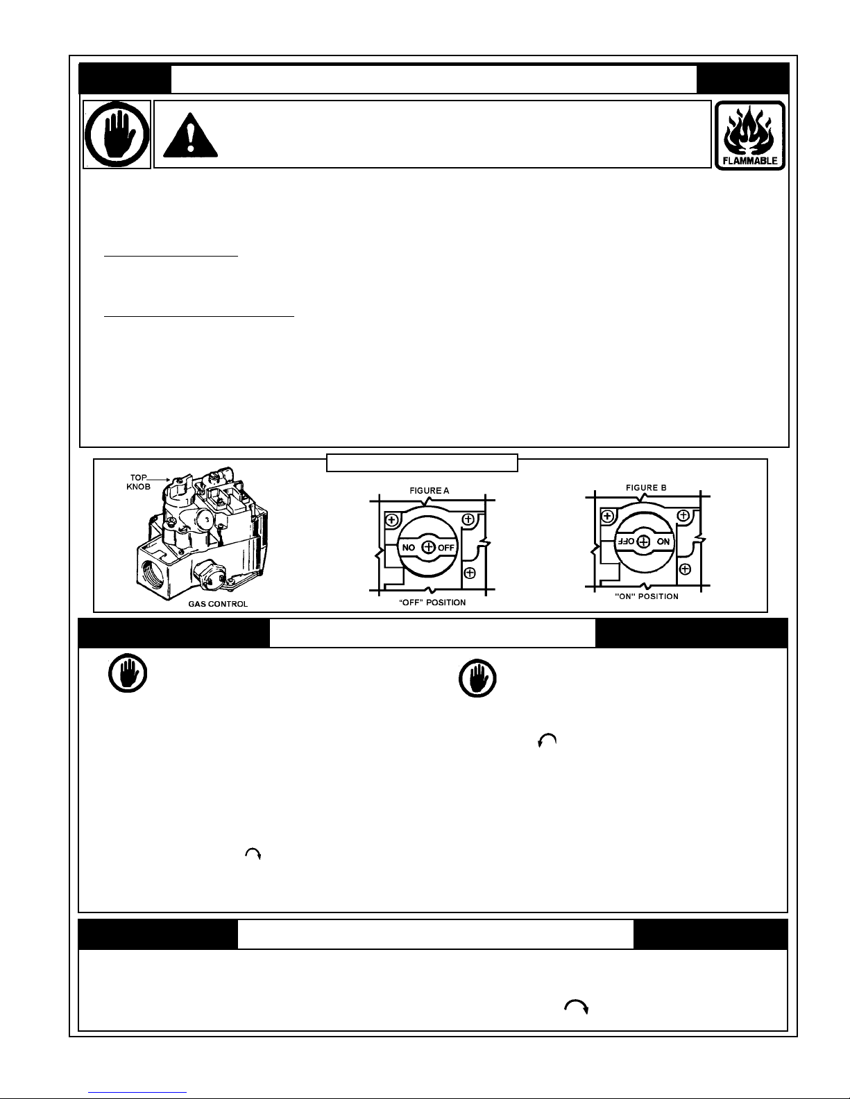
LIGHTING & OPERATION INSTRUCTIONS FOR MODELS LB/LW-500 ONLY:
FOR YOUR SAFETY READ BEFORE OPERA TING
WARNING: IF YOU DO NOT FOLLOW THESE INSTRUCTIONS EXACTLY , A FIRE OR
EXPLOSION MA Y RESUL T CAUSING PROPERTY DAMAGE, PERSONAL INJURY OR
LOSS OF LIFE.
A. THIS APPLIANCE DOES NOT HAVE A PILOT. IT IS
EQUIPPED WITH AN IGNITION DEVICE WHICH
AUTOMATICALLY LIGHTS THE BURNER. DO NOT TRY
TO LIGHT THE BURNER BY HAND.
B.
BEFORE LIGHTING: SMELL ALL AROUND THE
APPLIANCE AREA FOR GAS. BE SURE TO SMELL NEXT
TO THE FLOOR BECAUSE SOME GAS IS HEA VIER THAN
AIR AND WILL SETTLE ON THE FLOOR.
WHAT TO DO IF YOU SMELL GAS
• DO NOT TRY TO LIGHT ANY APPLIANCE.
• DO NOT TOUCH ANY ELECTRIC SWITCH;
DO NOT USE ANY PHONE IN YOUR BUILDING.
• IMMEDIA TELY CALL YOUR GAS SUPPLIER FROM A
NEIGHBOR’S PHONE. FOLLOW THE GAS
SUPPLIER’S INSTRUCTIONS.
• IF YOU CANNOT REACH YOUR GAS SUPPLIER,
CALL THE FIRE DEP ARTMENT.
ROBERTSHAW
C. USE ONLY YOUR HAND TO PUSH IN OR TURN THE GAS
CONTROL KNOW . V AL VE HANDLE. NEVER USE TOOLS.
IF THE HANDLE WILL NOT TURN BY HAND, DON’T TRY
TO REP AIR IT , CALL A QUALIFIED SERVICE TECHNICIAN.
FORCE OR A TTEMPTED REP AIR MA Y RESUL T IN A FIRE
OR EXPLOSION.
D. DO NOT USE THIS APPLIANCE IF ANY P ART HAS BEEN
UNDER WATER. IMMEDIATELY CALL A QUALIFIED
SERVICE TECHNICIAN TO INSPECT THE APPLIANCE
AND TO REPLACE ANY PART OF THE CONTROL SYSTEM
AND ANY GAS CONTROL WHICH HAS BEEN UNDER
WATER.
E. DO NOT OPERA TE APPLIANCE UNLESS UNIT IS FILLED
WITH WA TER AND W A TER LINES ARE FULL Y OPEN.
®
GAS CONTROL
OPERA TING INSTRUCTIONS
1. STOP! READ THE SAFETY INFORMA TION
ABOVE ON THIS LABEL.
2. SET THE SYSTEM CONTROLLER TO THE LOWEST
SETTING.
3. TURN POWER SWITCH ON APPLIANCE TO “OFF”
POSITION (SWITCH LIGHT GOES OUT).
4. THIS APPLIANCE IS EQUIPPED WITH AN IGNITION
DEVICE WHICH AUTOMA TICALL Y LIGHTS THE BURNER.
DO NOT TRY TO LIGHT THE BURNER BY HAND.
5. REMOVE TOP COVER TO EXPOSE GAS CONTROL.
6. REFER TO DIAGRAMS ABOVE. TURN TOP KNOB OF GAS
CONTROL CLOCKWISE
7. WAIT FIVE (5) MINUTES TO CLEAR OUT ANY GAS. THEN
SMELL FOR GAS, INCLUDING NEAR THE FLOOR. IF YOU
SMELL GAS,
TO “OFF” POSITION, (FIG. A).
8. TURN TOP KNOB OF GAS CONTROL COUNTER-
9. REPLACE TOP COVER.
10. TURN POWER SWITCH TO “ON” POSITION (SWITCH
11. SET THE SYSTEM CONTROLLER TO DESIRED SETTING.
12. IF THE APPLIANCE WILL NOT OPERATE, FOLLOW THE
STOP ! FOLLOW “B” IN THE SAFETY INFORMA TION
ABOVE ON THIS LABEL. IF YOU DON’T SMELL
GAS, GO TO THE NEXT STEP .
CLOCKWISE
LIGHT COMES ON).
INSTRUCTIONS “TO TURN OFF GAS TO THE APPLIANCE”
AND CALL YOUR SERVICE TECHNICIAN OR GAS
SUPPLIER.
TO “ON” POSITION, (FIG. B).
TO TURN OFF GAS TO APPLIANCE
1. SET THE SYSTEM CONTROLLER TO THE LOWEST SETTING .
2. TURN POWER SWITCH ON APPLIANCE TO “OFF” POSITION (SWITCH LIGHT GOES OUT).
3. REMOVE TOP COVER TO EXPOSE GAS CONTROL.
4. REFER TO DIAGRAMS ABOVE. TURN TOP KNOB OF GAS CONTROL CLOCKWISE
5. REPLACE TOP COVER.
TO "OFF" POSITION (FIG A).
® Robertshaw is a registered trademark of Robertshaw Controls Company Corporation.
25
Page 26
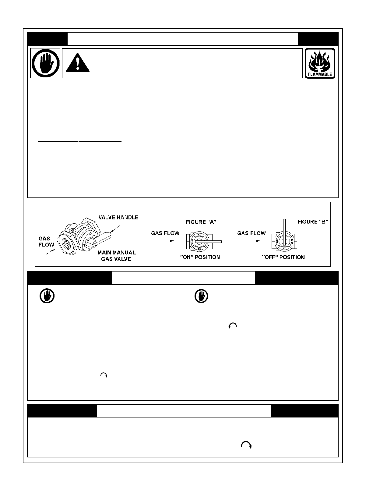
LIGHTING & OPERATION INSTRUCTIONS FOR MODELS LB/LW-750 AND 1000 ONLY:
FOR YOUR SAFETY READ BEFORE OPERA TING
WARNING: IF YOU DO NOT FOLLOW THESE INSTRUCTIONS EXACTLY, A
FIRE OR EXPLOSION MAY RESULT CAUSING PROPERTY DAMAGE,
PERSONAL INJURY OR LOSS OF LIFE.
A. THIS APPLIANCE DOES NOT HAVE A PILOT. IT IS
EQUIPPED WITH AN IGNITION DEVICE WHICH
AUTOMATICALLY LIGHTS THE BURNER. DO NOT TRY
TO LIGHT THE BURNER BY HAND.
B. BEFORE LIGHTING: SMELL ALL AROUND THE
APPLIANCE AREA FOR GAS. BE SURE TO SMELL NEXT
TO THE FLOOR BECAUSE SOME GAS IS HEA VIER THAN
AIR AND WILL SETTLE ON THE FLOOR.
WHAT TO DO IF YOU SMELL GAS
• DO NOT TRY TO LIGHT ANY APPLIANCE.
• DO NOT TOUCH ANY ELECTRIC SWITCH;
DO NOT USE ANY PHONE IN YOUR BUILDING.
• IMMEDIA TEL Y CALL YOUR GAS SUPPLIER FROM A
NEIGHBOR’S PHONE. FOLLOW THE GAS
SUPPLIER’S INSTRUCTIONS.
• IF YOU CANNOT REACH YOUR GAS SUPPLIER,
CALL THE FIRE DEP ARTMENT.
C. USE ONLY YOUR HAND TO PUSH IN OR TURN THE GAS
CONTROL KNOB. NEVER USE TOOLS. IF THE KNOB
WILL NOT PUSH IN OR TURN BY HAND, DON’T TRY TO
REPAIR IT, CALL A QUALIFIED SERVICE TECHNICIAN.
FORCE OR A TTEMPTED REP AIR MA Y RESUL T IN A FIRE
OR EXPLOSION.
D. DO NOT USE THIS APPLIANCE IF ANY P ART HAS BEEN
UNDER WATER. IMMEDIATELY CALL A QUALIFIED
SERVICE TECHNICIAN TO INSPECT THE APPLIANCE
AND TO REPLACE ANY P ART OF THE CONTROL SYSTEM
AND ANY GAS CONTROL WHICH HAS BEEN UNDER
WATER.
E. DO NOT OPERATE APPLIANCE UNLESS UNIT IS FILLED
WITH WA TER AND W A TER LINES ARE FULL Y OPEN.
.
OPERA TING INSTRUCTIONS
1. STOP! READ THE SAFETY INFORMA TION
ABOVE ON THIS LABEL.
2. SET THE SYSTEM CONTROLLER TO THE LOWEST
SETTING .
3. TURN POWER SWITCH ON APPLIANCE TO “OFF”
POSITION (SWITCH LIGHT GOES OUT).
4. THIS APPLIANCE IS EQUIPPED WITH AN IGNITION
DEVICE WHICH AUTOMA TICALL Y LIGHTS THE BURNER.
DO NOT TRY TO LIGHT THE BURNER BY HAND.
5. REMOVE TOP COVER TO EXPOSE GAS CONTROL.
6. REFER TO DIAGRAMS ABOVE. TURN TOP KNOB OF GAS
CONTROL CLOCKWISE
7. WAIT FIVE (5) MINUTES TO CLEAR OUT ANY GAS. THEN
SMELL FOR GAS, INCLUDING NEAR THE FLOOR. IF YOU
SMELL GAS,
TO “OFF” POSITION, (FIG . A).
8. TURN TOP KNOB OF GAS CONTROL COUNTER-
9. REPLACE TOP COVER.
10. TURN POWER SWITCH TO “ON” POSITION (SWITCH
11. SET THE SYSTEM CONTROLLER TO DESIRED SETTING .
12. IF THE APPLIANCE WILL NOT OPERA TE, FOLLOW THE
STOP ! FOLLOW “B” IN THE SAFETY INFORMA TION
ABOVE ON THIS LABEL. IF YOU DON’T SMELL
GAS, GO TO THE NEXT STEP .
CLOCKWISE TO “ON” POSITION, (FIG. B).
LIGHT COMES ON).
INSTRUCTIONS “TO TURN OFF GAS TO THE APPLIANCE”
AND CALL YOUR SERVICE TECHNICIAN OR GAS
SUPPLIER.
TO TURN OFF GAS TO APPLIANCE
1. SET THE SYSTEM CONTROLLER TO THE LOWEST SETTING.
2. TURN POWER SWITCH ON APPLIANCE TO “OFF” POSITION.
3. REMOVE TOP COVER TO EXPOSE GAS CONTROL.
4. REFER TO DIAGRAMS ABOVE. TURN TOP KNOB OF GAS CONTROL CLOCKWISE
5. REPLACE TOP COVER.
TO "OFF" POSTION (FIG. A).
Page 27
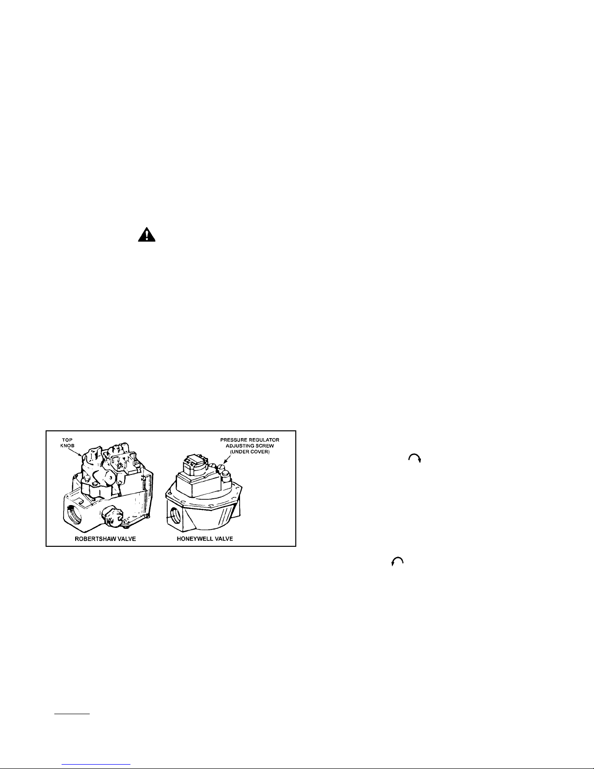
in the combustion chamber to clear. IF YOU DETECT GAS ODOR
AT THE END OF THIS PERIOD DO NOT PROCEED WITH LIGHTING.
RECOGNIZE THAT GAS EVEN IF IT SEEMS WEAK, MA Y INDICATE
PRESENCE OF ACCUMULA TED GAS SOMEPLACE IN THE AREA
WITH RISK OF FIRE OR EXPLOSION. SEE THE FRONT PAGE FOR
STEPS TO BE T AKEN.
INLET GAS PRESSURE
The inlet gas pressure is measured at the main manual gas
shut-off valve, which is upstream of the unit’s gas valves and
pressure regulators. The maximum supply pressure of
13.8 inches W.C. (3.44 kPa) must not be exceeded. The
minimum values are shown in the GAS AND ELECTRICAL
CHARACTERISTICS table on pages 2 and 3 of this manual. The
gas valves supplied with the boiler are for low pressure service.
If the upstream pressure exceeds 13.8 inches W.C. (3.44 kPa) an
intermediate gas pressure regulator of the lockup type must be
installed.
CAUTION
SHOULD OVERHEATING OCCUR OR THE GAS SUPPLY F AIL TO
SHUT OFF, SHUT OFF THE GAS SUPPLY AT A LOCATION
EXTERNAL TO THE BOILER (i.e. MAIN MANUAL GAS SHUTOFF
VA LVE).
LIGHT THE BOILER IN ACCORDANCE WITH THE INSTRUCTIONS
PROVIDED ON THE LABEL AFFIXED TO THE BOILER’S FRONT
DOOR ON THE INSIDE. THESE INSTRUCTIONS ARE REPEA TED
IN DETAIL ON THE FOLLOWING PAGE.
MANIFOLD PRESSURE CONNECTIONS
Take the manifold pressure, refer to figure 15, by removing the
pipe plug and inserting a suitable 1/8” NPT hose barb for
connection to the manometer/pressure gauge. Upon completion
of measurements and adjustments, remove the hose barb and
replace the pipe plug. Check for gas leaks and insure all
connections are gas tight.
maintained when all gas appliances connected to the system
are operating simultaneously and at full fire supply. Pressure
drops of more than 1/2” w.c. (0.12 kPa) are not acceptable.
The designed manifold pressures are 3.5 in. w.c. (0.87 kPa) for
natural gas and 10.0 in. w.c. (2.49 kPa) for propane gas. In order
to check and/or adjust the pressure regulator setting, perform
the following:
1. Set the system controller at its lowest setting so that the boiler
will not call for heat.
2. Refer to Figure 15 and MANIFOLD PRESSURE CONNECTIONS
for the proper method of measuring manifold pressure.
3. Reset the system controller dial to desired setting
(ensure ON/OFF switch is “ON”). The main burner will ignite.
4. With the main burner firing, adjust the pressure, if necessary, by
turning the pressure regulator adjusting screw with a
slot-type screwdriver. The pressure should be 3.5 in. w.c. (0.87
kPa) for natural gas or 10.0 in. w.c. (2.49 kPa) for propane gas.
• Clockwise to increase pressure.
• Counterclockwise to decrease pressure.
5. Set the system controller to lowest setting.
6. Remove pressure gauge and replace pipe plug in pipe nipple.
7. Set the system controller to desired setting.
DO NOT INCREASE THE PRESSURE ABOVE THA T SPECIFIED ON
THE RATING PLA TE, AS OVER-FIRING WILL RESULT IN DAMAGE
TO THE BOILER.
If the gas pressure regulator cannot be adjusted to the correct
pressure, and there is sufficient gas supply pressure at the valve,
replace with a new gas valve (in the case of propane boilers,
replace with a new gas pressure regulator).
SAFETY CHECKS
After placing the boiler in operation, perform the following steps
to ensure proper performance:
FOR LB/LW -500 MODELS:
FIGURE 18. HONEYWELL VAL VE
GAS PRESSURE REGULATORS
For natural gas boilers, the gas pressure regulator is included in
the combination gas valve, figure 18. For propane boilers, the
gas pressure regulator is a separate device (except on the LW500 model), figure 15. The gas pressure regulator is factory set
to operate on the gas specified on the boiler rating plate.
DO NOT subject the gas valve to inlet gas pressures of more than
13.8 in. w.c. (3.4 kPa). If higher gas pressures are encountered,
a service regulator is necessary.
A
minimum supply gas pressure of 7.0" in. w.c. (2.74 kPa ) for
Natural Gas, or 1 1.0 in. w.c. (2.49 kPa) for Propane Gas, must be
maintained. The minimum supply gas pressure must be
1. Manually shut off the gas supply by turning the top knob of the
gas control clockwise to the “OFF” position. The boiler
will shut down (main burner extinguished) and will try and
re-light within 15 seconds. After three (3) ignition attempts
(or 1 attempt on CSD-1 models) the system will lock out. Check
that there is no voltage across the D-D or TH-TR terminals on
the gas control. Proceed to Step 2.
2. Shut off the gas supply to the boiler by closing the main manual
gas shutoff valve in the gas supply line located outside of the
boiler cabinet. Turn the top knob on the gas control
counterclockwise
to the boiler by turning the power switch on the boiler to the
“OFF” position, wait one (1) minute and then turn to the “ON”
position. If there is sufficient gas supply pressure to hold the
low gas pressure switch contacts closed, the unit will proceed
with the Trial-For-Ignition and as soon as the gas control opens,
the Gas Pressure Fail Light (red) on the DIA-SCAN II display
will come on and the gas control will close. If the gas supply
pressure is low where the low gas pressure switch contacts
remain open, the Gas Pressure Fail Light (red) on the
DIA-SCAN II display will remain on. The boiler will remain in
this state for approximately two minutes and then proceed to
enter lock out mode. Check that there is no voltage across the
gas control terminals before and after the unit enters the lock
out mode. The lock out message under this condition should
be either “Circulation Fail” or “Inducor Fail” depending upon
the state of the switch when the cycle is initiated.
to the “ON” position. Reset the power
Page 28
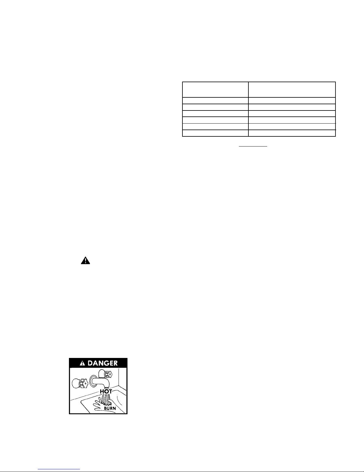
FOR LB/LW-750 AND LB/L W-1000 MODELS:
1. Manually shut off the gas supply by one of the two methods.
On boilers that have a manual shutoff valve downstream from
the automatic gas valves, turn the manual shut off valve to the
“OFF” position. On boilers that do not have the manual shut
off valve located downstream from the automatic valve, the
gas supply must be interrupted at the automatic valves to
perform this check. This may be done by disconnecting the
24 volt lead that supplies the valves. The boiler will shut down
(main burner extinguished) and will try and re-light within 15
seconds. After three (3) ignition attempts (or 1 attempt on
CSD-1 models) the system will lock out. Once lockout has
occurred, check to insure that there is no voltage across the
terminals on the gas control or leading to the gas control in
the case where the lead was disconnected. Return all valves
and wires to their original positions and proceed to Step 2.
2. Shut off the gas supply to the boiler by closing the main manual
gas shut off valve in the gas supply line located outside of the
boiler cabinet. Reset the power to the boiler by turning the
power switch on the boiler to the “OFF” position, wait one (1)
minute and then turn to the “ON” position. If there is sufficient
gas supply pressure to hold the low gas pressure switch
contacts closed, the unit will proceed with the Trial-For-Ignition
and as soon as the gas control opens, the Gas Pressure Fail
Light (red) on the DIA-SCAN II display will come on and the
gas control will close. If the gas supply pressure is low where
the low gas pressure switch contacts remain open, the Gas
Pressure Fail Light (red) on the DIA-SCAN II display will remain
on. The boiler will remain in this state for approximately two
minutes and then proceed to enter lock out mode. Check that
there is no voltage across the gas control terminals before
and after the unit enters the lock out mode. The lock out
message under this condition should be either “Circulation
Fail” or “Inducer Fail” depending upon the state of the switch
when the cycle is initiated.
DANGER
HOT WATER TEMPERATURES REQUIRED FOR AUTOMATIC
DISHWASHER AND LAUNDRY USE CAN CAUSE SCALD
BURNS RESULTING IN SERIOUS PERSONAL INJURY AND/OR
DEA TH. THE TEMPERATURE AT WHICH INJUR Y OCCURS VARIES
WITH THE PERSON'S AGE AND TIME OF EXPOSURE. THE
SLOWER RESPONSE TIME OF CHILDREN, AGED OR DISABLED
PERSONS INCREASES THE HAZARDS TO THEM. NEVER ALLOW
SMALL CHILDREN TO USE A HOT WATER TAP , OR TO DRAW
THEIR OWN BA TH WA TER. NEVER LEAVE A CHILD OR DISABLED
PERSON UNA TTENDED IN A BA THTUB OR SHOWER.
THE WA TER HEA TER SHOULD BE LOCATED IN AN AREA WHERE
THE GENERAL PUBLIC DOES NOT HAVE ACCESS TO SET
TEMPERATURES.
energy efficient operation of the boiler and minimize scale
formation in the heat exchanger, thus prolonging the life of the
boiler.
SETTING THE WA TER HEA TER TEMPERA TURE A T 120°F (49°C)
WILL REDUCE THE RISK OF SCALDS. Some states require
settings at specific lower temperatures. Table 9 below shows
the approximate time-to-burn relationship for normal adult skin.
TABLE 9. Risk of Scalds
Temperature Time to Produce 2nd & 3rd
Setting Degree Burns on Adult Skin
Over 170°F (77°C) Nearly instantaneous
160°F (71°C) About 1/2 second
150°F (66°C) About 1-1/2 seconds
140°F (60°C) Less than 5 seconds
130°F (54°C) About 30 seconds
120°F (49°C) or less More than 5 minutes
Valves for reducing the
and hot water are available. Also available are inexpensive
devices that attach to faucets to limit hot water temperatures.
Contact a licensed plumber or the local plumbing authority.
SHOULD OVERHEATING OCCUR OR THE GAS SUPPLY FAIL
TO SHUT OFF, TURN OFF THE MAIN MANUAL GAS SHUTOFF
VA LVE TO THE APPLIANCE.
point-of-use temperatures by mixing cold
WATER TEMPERATURE REGULATION
The operating temperature of the boiler must be maintained as
follows:
• 140°F (60°C) or higher inlet water temperature to the boiler.
• 20°F (11°C) differential between the boiler’s inlet and outlet
(e.g. 140°F [60°C] inlet, 160°F [71°C] outlet minimum design
temperatures).
If the inlet water temperature into the boiler is less than 140°F
(60°C), adjustments on the water bypass and the outlet valves at
the rear of the boiler, figures 13 and 14, are required; wait at least
one minute between adjustments for the temperature to stabilize.
1) If necessary, throttle down (close) the water outlet gate/ball
valve until the desired outlet water temperature (160°F [71°C]
minimum) is reached. Wait one minute.
2) Note the outlet and inlet temperature indicator readings.
a) If the inlet water temperature is less than 140°F (60°C),
open, in small increments, the bypass (balancing) valve
until the minimum 140°F (60°C) inlet water temperature
or 20°F (11°C) differential, whichever has the higher inlet
temperature, is attained.
It is recommended in domestic hot water applications that
lower water temperatures be used to avoid the risk of scalding.
It is further recommended, in all cases, that the water
temperature be set for the lowest temperature which satisfies
the user's hot water needs. This will also provide the most
b) If the inlet water temperature is greater than 140°F (60°C)
and the 20°F (11°C) differential is not present, close the
bypass valve until the 20°F (11°C) differential is attained.
NOTE: It may be necessary to make further adjustments on the
outlet and bypass valves until the desired inlet and outlet water
temperatures are reached.
SEQUENCE OF OPERATION
1. When power is applied to the WHC1502 ignition control, the
Display board will initially run through a self-diagnostic routine,
and then go into its operating mode, displaying the
temperature sensed at the outlet temperature probe.
28
Page 29

2. If the ignition control determines the actual water temperature
at the outlet temperature sensing probe is below the
programmed temperature set-point less the switching
differential, and the thermostat circuit is closed, a call for heat
is activated.
3. The control then performs selected system diagnostic
checks. This includes confirming the proper state of the ECO/
Manual Reset Limit device, flow switch, and pressure
switches.
4. If all checks are successfully passed, the circulating pump
circuit is energized then combustion blower is energized for
the 20 second pre-purge cycle.
5. When the pre-purge cycle is complete, power is applied to
the ignitor element for the ignitor warm-up period (pump and
blower should continue to run). Blower should go to low
speed when ignitor is powered.
6. The control will verify ignitor current. At the conclusion of the
ignitor warm-up period (17 seconds), the gas valve will open,
allowing gas to enter the burner.
7. After an additional 1 second, the control will monitor the flame
sense probe to confirm a flame is present. If a flame is not
verified within 4 seconds, the gas valve is immediately closed,
and the control will return to step 2.
NOTE: If the control is configured for one ignition trial, the
control will go into a lockout state at this point of the
operation.
8. If a flame is confirmed, the control will enter the heating mode
where it will continue heating until the set-point temperature
is reached, and the thermostat circuit is open. At that point,
the gas valve is closed and the control enters the post-purge
and post-circulate cycles.
9. The combustion blower will run for a 25 second post purge
cycle. When the post purge cycle is complete, the blower is
de-energized and will coast to a stop. The circulating pump
will continue with the post-circulate cycle for the programmed
amount of time (factory default 45 seconds). See Circulating
Pump Adjustment Procedure in Dia-Scan section of the
manual.
10. The control now enters the idle state while continuing to
monitor temperature and the state of other system devices. If
the temperature drops below the set-point value minus the
switching differential, and the thermostat circuit closes, the
control will return to step 2 and repeat the entire operating
cycle. During this idle state, if the control detects an improper
operating state for external devices such as the ECO switch,
air pressure switch, gas pressure switch, etc., the appropriate
LED(s) on the Display Board will illuminate or, error message
will scroll indicating the nature of the fault.
MAINTENANCE
every six months. All relief valves should be inspected and
manually operated at least twice a year.
VENTING MAINTENANCE
It is recommended that the venting system be checked monthly
by a qualified professional for dust, deterioration, carbon deposits
and foreign debris.
Normal operation of this boiler does not result in deposits of soot
in the vent system. However, if soot or other debris is found to be
in the venting system or as indicated by BLOCKED FLUE on the
display board, it must be removed in order for the boiler to operate
properly. An authorized service agent should be contacted to
determine the reason for sooting.
The venting system should be inspected monthly not only for
soot and other debris but also for signs of condensate leakage
or combustion products at all joints. If any leakage is found, the
boiler should be turned off (see “Lighting and Operating
Instructions” to turn boiler off), and the leaks must be repaired.
Any damaged or deteriorated venting parts must be replaced.
CAUTION
DO NOT USE A NYLON BRUSH OR OTHER STATIC CREATING
MA TERIAL TO CLEAN THE VENT. DEPOSITS SUCH AS DUST
AND CARBON SOOT COULD BE FLAMMABLE AND MAY BE
IGNITED BY ST A TIC ELECTRICITY . THEREFORE, USE A META L
BRUSH TO MINIMIZE THE DANGER OF EXPLOSION.
THE FOLLOWING CHECKS ARE CARRIED OUT WITH THE
BOILER SHUT DOWN:
TO INSPECT THE VERTICAL VENT
The vertical vent terminal is not (or should not be) sealed to the
vent pipe; therefore, simply lift off the terminal to begin inspection.
After inspection, replace the terminal but do not seal it into position.
If a Saf-T Vent Rain Cap is used, pry up the locking tabs that
secure it to the vent pipe and remove the cap. After inspection,
replace the cap by inserting the locking tabs back under the ring
and bending them back into position. The system can also be
inspected and cleaned by removing a vent pipe or fitting.
TO INSPECT A SEALED VENT SECTION
Pry up the locking tabs on both sides of the chosen piece to be
removed. Carefully cut and remove the silicone sealant located
in between the joints so as to not damage the parts. Take off the
vent piece and clean up any remaining silicone sealant present
on the exposed venting sections. After inspection, replace the
vent piece carefully and correctly.
TO INSPECT THE CONDENSA TE DRAIN HOSE
Check at the same time the venting system is inspected to ensure
that the condensate is allowed to flow out to a suitable drain. It is
also important to have and maintain water in the trap loop to
prevent the products of combustion from escaping into the
room area, see “CONNECTING VENT TO BOILER” and
“CONDENSA TE REMOVAL SYSTEM”.
At Start-Up and at least every six months thereafter, the boiler
should be checked for proper operation of the WHC-1502 Ignition
Control and all safety shutoff devices by checking against the
Sequence of Operation. The devices on the boiler including, but
not limited to, water temperature controls, water flow switch, air
pressure switches, gas pressure switches, manual shutoff
valve(s) and electrically operated valve(s) should also be checked
for proper operation. The safety shutoff valves should be
inspected for gas tightness. Any safety devices including Low
Water Cutoffs used in conjunction with this boiler should receive
periodic (every six months) inspection to assure proper operation.
A Low Water Cutoff device of the float type should be flushed
BURNER AND FLAME PATTERN
To maintain safe operation and the greatest efficiency from the
boiler, the burner should be checked by a qualified service agency
once every six months for proper flame characteristics.
The burner, figure 19, should display the following characteristics:
• Provide complete combustion of gas.
• Cause rapid ignition and carryover of flame across entire burner.
• Give reasonably quiet operation during ignition, burning and
extinction.
• Cause no excessive lifting of flame from burner port.
29
Page 30
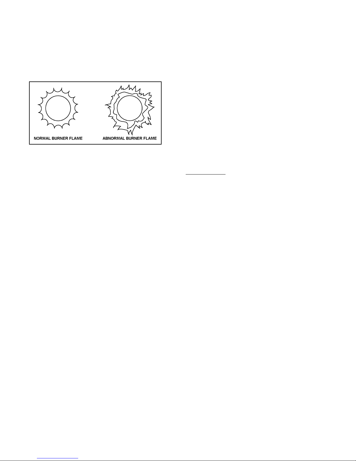
Flame pattern should have hard, uniform blue flames surrounding
the burner, see figure 19.
If the flame is pulsing, floating, yellow and/or lifting off the burner,
check the manifold gas pressure and combustion air supply;
maintain a clear area around the boiler at all times.
If the aforementioned flame characteristics are not evident, check
for accumulation of lint or other foreign material that restricts or
blocks the air/gas openings to the burner or boiler.
FIGURE 19. BURNER FLAMES
BURNER MAINTENANCE
Qualified servicers should follow this procedure when the boiler’s
burner needs cleaning.
1. Turn off the electrical power to the boiler and close the main
manual gas shutoff valve(s). Allow the boiler parts to cool before
disassembly.
2. Separate the blower from the manifold assembly by first
removing the four (4) screws, nuts and washers and
subsequently, the blower gaskets and air orifice. Then loosen
the nut that holds the blower bracket which supports the
blower. The blower should be free to move at this point.
FOR DIRECT VENT UNITS: It is necessary to loosen and slide
the rubber coupling on the blower adaptor in order to move the
blower.
3. Loosen the union orifice and separate the gas train from the
manifold assembly.
4. Loosen the nuts (7) at the manifold base and move the burner
ground wire (Green) aside.
5. Lift the manifold assembly up from the six (6) studs located on
the cover plate and remove the burner gasket.
6. Lift the burner and cone assembly up from the cover plate.
Ensure that the white insulation disc (1/2” [13 mm] thick, 3 3/4”
[9.5 cm] diameter) is attached to the burner base (closed end).
7. Remove any loose foreign material such as dust or lint with a
vacuum. Check all ports for blockage. Dislodge any foreign
material causing blockage. Remove any soot or carbon
deposits with a rag making sure to remove any lint left on the
burner by vacuuming again.
9. Restore electrical power and gas supply to the boiler.
• Put the boiler back in operation by following the Lighting
and Operating instructions in this manual.
• Check for gas leaks and proper boiler and vent operation.
CONDENSATE REMOVAL SYSTEM
Due to the highly efficient operation of this unit, condensate is
formed during operation and must be removed by the condensate
drain systems. Inspect the condensate drains and tubes at least
once a month and insure they will allow the free flow of
condensate at all times. The system must be inspected more
frequently in cold weather if the drain system is located in an
area, such as along the floor, where freezing temperatures are
likely to occur. The condensate drain system must be protected
against freezing. Contact a qualified service agent to inspect and
correct the condition if freezing of the condensate lines is a
problem. The unit is equipped with a blocked flue switch which
will shut the unit off if condensate is unable to drain and backs up
in the unit. The Dia-Scan II display board red light indication
when sufficient condensate accumulates for this condition will
be BLOCKED FLUE.
The transparent drain lines and condensate drain on the bottom
of the vent collector should be visually inspected at one month
intervals for blockage, particularly in the areas of the loops in the
lines which trap a small amount of condensate, and the exit point
of the vent collector drain. Condensate in portions of the line
other than the loop area indicates a blockage in the drain line.
Flush the lines with air or water and clear or replace the blocked
portions of the line as necessary. Note that areas of the drain line
which include a sag or low spot in the line will also form a
condensate trap which can be removed by levelling the tube and
does not indicate a blocked system.
Inspect the metal vent drain and vent collector drain connectors
at six month intervals. Remove the hoses from the connections,
then check with a small wooden dowel or plastic rod passed up
through the metal connection to insure the passage is clear,
using caution to not bend or damage the connector. Call a
qualified service agent to inspect and correct the problem if any
obstructions are found in the connectors. Replace all hoses and
clamps immediately after inspection and before starting the boiler
in accordance with the Lighting and Operating Instructions.
DO NOT OPERATE THE BOILER UNLESS ALL CONDENSATE
DRAIN LINES ARE PROPERL Y CONNECTED AND WORKING . When
a means to neutralize condensate has been installed you must
also follow operating, inspection and maintenance procedures
specified by the manufacturer of the product. Inspect the installed
device to insure that it does not cause condensate to remain in
the boiler or vent for any reason.
DIA-SCAN II
SELF DIAGNOSTIC SYSTEM
8. Reverse the steps to reassemble the unit.
Ensure that the insulation disc is affixed to the burner base. If
not, clean the burner base from the residual insulation. Apply
spray adhesive to the cleaned area and press the insulation
against the base. Allow it to set a sufficient time before
reassembly.
The WHC1502 ignition control is a fully integrated, state of the art
electronic control system. The ignition control includes a
microprocessor, which governs all temperature and ignition
control functions for the appliance.
Inherent in the design are the normal operating sequences and
safety features associated with a gas ignition control system.
30
Page 31
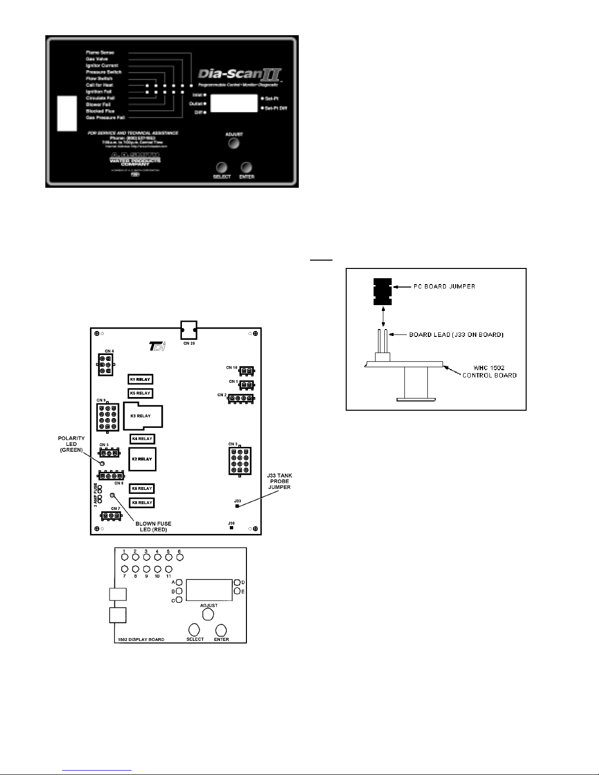
FIGURE 20.
The ignition control continuously performs various diagnostic
tests to verify proper appliance and control operation. Should an
unsafe condition occur, the control will shut down the burner and
illuminate the appropriate diagnostic indicators on the Display
Board, figure 20, indicating a need for service. All operating
programs are stored in permanent memory on the ignition control
and a second programmable memory is used for retaining user
specific operating parameters in the event main power is ever
interrupted. If a failure lock-out occurs, the board must be reset
by depressing the enter/reset button on the display board,
indicating a need for service.
24-Volt method of temperature control, the J33 jumper must
be removed and the red/green wires in the junction box at the
rear of the unit must be used. (see figure 21 and 22). Standard
LB models will not have a jumper across the J33 board leads.
Wires are provided in the junction box for a 24-V olt method of
temperature control.
LINE POLARITY INDICA TOR
A green LED is mounted on the ignition control board to indicate
line voltage polarity is properly connected. When 120 VAC input
power is properly connected to the ignition Control Board, the
green LED will illuminate. If an error is made when connecting
120 V AC input power, this LED will not light. Improperly connecting
the input power may result in a false flame sensor failure.
FUSE PROTECTION
The 24 VAC circuitry is protected with a 3 amp auto fuse. If the
fuse opens, a red LED located near the fuse will light. If the red
LED is illuminated, replace the fuse. Repeated failure of the
fuse is an indication of possible damage to the ignition control.
Note: An extra fuse and 1 jumper are supplied with the boiler .
FIGURE 21. DIA-SCAN II CONTROL AND DISPLA Y BOARD
NOTE: PC board jumpers are used on the WHC 1502 (see
figure 21) to control the mode of temperature regulation (tank
probe or 24 V control) and number of ignitions trials (Standard
VS. CSD-1 Models). The jumper is a small rectangular plastic
piece which fits over two control board leads (see figure 22). It
is used on LW models to allow for the use of the tank probe
provided with the unit. If the installer wishes to use an alternate
FIGURE 22.
DIA-SCAN II DISPLA Y BOARD
OPERATING PROCEDURES
The Display Board, figure 20, provides a user friendly interface to
the WHC1502 Ignition Control Board. With the Display Board,
the user can control appliance functions and view the overall
operating status of the appliance. If an error condition occurs,
the Display Board will scroll a diagnostic message across the
LED display. Under normal operating conditions, the four digit
LED display on the Display Board will continuously illustrate the
water temperature sensed at the outlet temperature probe. The
push buttons on the Display Board are connected to the Ignition
Control Board through a 6 conductor cable assembly with modular
plug terminations. In addition, an 8 conductor modular jack on
the Display Board allows for connecting a remote display board.
When power is applied to the WHC1502 System, the Display
Board will initially run through a self-diagnostic test, and then
display the Outlet temperature. If the Tank Probe is connected to
the board the tank temperature will be displayed. To display a
specific setting or temperature, press the SELECT push-button
until the appropriate LED is illuminated (see figure 20). After 5
seconds, the Display Board will automatically revert to display
the Outlet temperature. Pressing the ENTER/RESET push-button
will hold the display in the indicated mode until the SELECT pushbutton is pressed.
With the display board, the user can make adjustments to many
of the appliance’s control features. This includes the following:
31
Page 32

Options/Features Setting Procedures:
• Set Appliance Temperature Set-Point Value
• Set Appliance Switching Differential Value
• Select Appliance Post-Circulate Time
• Set Appliance Circulating Pump Mode
• Check Appliance Cycle Count
• Control the water temperature in a storage tank
Green Status Lights:
LED 1: Call for Heat
LED 2: Flow Switch
LED 3: Pressure Switch
LED 4: Ignitor Current
LED 5: Gas Valve
LED 6: Flame Sensor
Red Fault Lights:
LED 7: Ignition Fail
LED 8: Circulate Failure
LED 9: Blower Failure
LED 10: Blocked Flue
LED 11: Gas Pressure Failure
Water Temperature Set Lights:
LED A: Inlet Water T emperature*
LED B: Outlet Water Temperature
LED C: Inlet/Outlet Differential Temperature
LED D: Set-Point Temperature
LED E: Outlet/Set-Point Differential Temperature
*Defaults to water temperature sensor when third
temperature probe (Tank Probe) is used.
If the ADJUST push-button is held down long enough, the setpoint will reach 1 10°F [43°C], the minimum value (or 240°F [115°C],
the maximum value) and stop. At this point, if the desired setting
is not obtained, release the ADJUST push-button and depress it
again. The set-point value will now restart at 1 10°F [43°C] (240°F
[115°C]) and once again increase (decrease) in value for as long
as the ADJUST push-button is pressed.
NOTE: The boiler must complete a full cycle in order for the
new setting to take effect. If the unit is turned off prior to a
complete cycle, the setting will be lost and the previous setting
will remain in effect.
NOTE: If the tank probe is connected to the system, the
appliance Set-Point temperature will only act as a back-up to
the system temperature, which will be controlled through the
tank probe. (See Tank Probe Sensor/Heating System
Temperature Sensor Section of manual). If a tank probe is
being utilized (LW Models), it is recommended that the appliance
set-point be at least 30°F [17°C] above the tank probe setpoint. This is also true if using an alternate 24 Volt control for
tank or loop temperature regulation.
NOTE: Do not use the appliance Set-Point temperature as the
system temperature regulation device in hydronic (LB)
applications. An external 24-V olt temperature control located
in the return loop of the closed water system should be used
for system regulation. This device should be attached to the
red/green wires in junction box at the rear of the unit. The
appliance temperature setting should only be used as a limit
control for the system.
TEMPERATURE SET-POINT ADJUSTMENT
PROCEDURE FOR APPLIANCE
Setting this temperature determines where the appliance will shut
down. It is controlled by the outlet/ECO temperature probe on the
outlet of the unit. In most cases, it should be set approximately 30
degrees (17°C) above the thermostat or tank probe temperature
setting. The controller has a standard programmable temperature
set-point range of 110°F (43°C) to 240°F (115°C). The user can
easily change the temperature set-point at any time by using the
following procedure. In all cases, you must apply input power to
the controller to perform any programming operations. The factory
default setting is 180°F (82°C).
To change or view the current programmed temperature set-point
value:
1. Press the SELECT push-button on the display board until both
the Set-Pt LED (LED D, see figure 21) and Outlet Water
Temperature LED (LED B, see figure 21) are illuminated.
2. The LED display will show the current set-point temperature.
3. Press and hold the ADJUST push-button. The displayed
temperature will either increase or decrease. To alternate
between increasing or decreasing the temperature, release
then press and hold the ADJUST push-button.
4. When the desired set-point temperature is reached, release
the ADJUST push-button.
5. Press the ENTER/RESET push-button once, this enters the
selected set-point temperature into controller memory.
SWITCHING DIFFERENTIAL ADJUSTMENT
PROCEDURE FOR APPLIANCE
T o facilit ate proper operation and maximize appliance performance,
the control has a programmable operating switching differential or
“hysteresis” about the set-point. This means a call for heat will
become active when the water temperature measured at the outlet
temperature sensing probe drops to the set-point value minus the
switching differential value. The burner will remain on until the
water temperature measured at the outlet temperature probe
reaches the set-point value. The switching differential value is fully
programmable from 5°F (3°C) to 50°F (28°C) using the pushbutton(s) located on the Display Board.
To change or view the current programmed switching differential:
1. Press the SELECT push-button on the display board until the
Set-Pt Diff LED (LED E, see figure 21) is illuminated.
2. The LED display will show the current switching differential.
3. Press and hold the ADJUST push-button. The displayed value
will either increase or decrease. To alternate between
increasing and decreasing the switching differential, release
then press and hold the ADJUST push-button.
4. When the desired switching differential is reached, release
the ADJUST push-button.
5. Press the ENTER push-button once, this enters the selected
switching differential value into controller memory.
6. The appliance will now control temperature utilizing the desired
switching differential value.
6. The appliance will now control the temperature to the desired
set-point value.
If the ADJUST push-button is held down long enough, the
switching differential setting will reach 5°F (3°C), the minimum
32
Page 33

value (or 50°F [28°C], the maximum value) and stop. At this point,
if the desired switching differential is not obtained, release the
ADJUST push-button and depress it again. The switching
differential value will now start at 5°F (3°C) to (50°F [28°C]) and
once again increase (decrease) in value for as long as the ADJUST
push-button is pressed.
CIRCULATING PUMP
ADJUSTMENT PROCEDURE
The Controller is factory set with a 45 second post circulate
function. With the Display Board, the user has the capability to
choose between a 45, 90, or 180 second post circulate time
period, or turn the pump on continuously. This provides flexibility
in selecting the post circulate time to meet specific installation
requirements, and improves the efficiency of the circulating pump
operation.
Table 10.
Display Message Appliance Mode
IdLe Idle state
NoSn Wait for No Sensor Inputs
CrSn Wait for Circulate Sense
Circ Circulate Pump is ON
PrSn Wait for Blower Pressure Sense
PreP Pre-Purge state
IGnt Ignitor Warm-up
rEdn Turn ON redundant Gas Valve relay
IAct Turn ON Gas Valves
StAb Tur n OFF I g nitor and wait for Flame
Sense Stabilization
HEAt Heat Mode
PoPC Post Purge and Post Circulate
Po C Post Circulate
DISPLAY TOTAL CYCLE COUNT
NOTE: It is recommended that intermittent post circulate pump
modes be used for maximum efficiency.
To change or view the current programmed post-circulating time:
1. Press the SELECT push-button on the display board until the
LED display reads OPt (Options).
2. To enter into the options mode, press the ENTER push-button.
3. The display will illustrate Circ. Enter this mode by pressing
the ENTER push-button.
4. The display will now illustrate the current post circulate time.
Press the ADJUST push-button to select the desired post
circulate time (45, 90, 180, On).
5. When you have selected the desired post circulate time mode,
press the ENTER push-button once, this enters the selected
post circulate time into controller memory.
6. The display will automatically return to showing the outlet
temperature.
DISPLAY CURRENT MODE
In this mode, the Display Board will show the current functional
step in the appliance operational sequence. For example, if the
appliance is performing Ignitor Warm-up, the display will show
IGnt. To enter into this mode, perform the following steps:
1. Press the SELECT push-button on the display board until the
LED display reads OPt (Options).
The Main Control Board counts the number of cycles the
appliance has operated. In the Main Control Board, a cycle is
counted every time the gas valve is energized. To access this
number, perform the following procedure:
1. Press the SELECT push-button on the display board until the
LED display reads OPt (Options).
2. To enter into the options mode, press the ENTER push-button.
3. The display will show Circ. Press the SELECT push-button
until the display shows Count. Enter this mode by pressing
the ENTER push-button.
4. The display will now show the current number of cycles the
appliance has cycled through.
5. The display will automatically resort to show the outlet
temperature
TANK PROBE TEMPERATURE SET-POINT
ADJUSTMENT PROCEDURE
The user can easily change the water temperature set-point at
any time by using the following procedure:
1. Press the SELECT push-button on the display board until both
the Set-Pt LED (LED D, see figure 21) and Inlet Water
Temperature LED (LED A, see figure 21) are illuminated.
NOTE : When a third probe is installed on the board at location
CN10, the Inlet Water T emperature LED default s to T ank Water
Temperature.
2. The LED display will show the current set-point temperature.
2. To enter into the options mode, press the ENTER push-button.
3. The display will show Circ. Press the SELECT push-button
until the display shows StEP. Enter this mode by pressing the
ENTER push-button.
4. The display will show the current appliance operating step.
5. The display will automatically resort to illustrating the outlet
temperature, after five (5) seconds. To keep the display in the
Display Step Mode, press ENTER twice in step 3.
3. Press and hold the ADJUST push-button. The displayed
temperature will either increase or decrease. To alternate
between increasing or decreasing the temperature, release
then press and hold the ADJUST push-button.
4. When the desired set-point temperature is reached, release
the ADJUST push-button.
5. Press the ENTER push-button once, this enters the selected
tank set-point temperature into controller memory.
6. The appliance will now control the water temperature to the
desired set-point value.
33
Page 34

If the ADJUST push-button is held down long enough, the
set-point will reach 110°F (43°C), the minimum value (or 190°F
[88°C], the maximum value) and stop. At this point, if the desired
set-point is not obtained, release the ADJUST push-button and
depress it again. The set-point value will now restart at 110°F
(43°C) to 190°F [88°C] and once again increase (decrease) in
value for as long as the ADJUST push-button is pressed.
Display Board LED Indicators
TROUBLESHOOTING
SHORTCYCLING
Shortcycling is a condition where the boiler starts up and shuts
down frequently in a short time period. This usually indicates
that an abnormal operating condition is present.
The Display Board contains eleven (1 1) solid st ate LED indicators
for viewing various states of appliance operation and for
troubleshooting if problems occur. Under normal operating
conditions, the appropriate LED’s will sequence with steady
illumination according to the particular appliance operating state.
In cases where problems or a lockout occurs, the appropriate LED’s
will illuminate indicating the general area where the problem exists.
A description of the LED’s and their corresponding functions are
as follows. See figure 20.
LED (GREEN) Controller Function
Call for Heat *** Monitors the outlet probe & switching
differential. LED is ON when the temperature
at the outlet is less than the set-point minus
the switching differential.
Flow Switch Monitors the condition of the flow switch.
LED is ON when the flow switch closes,
indicating water flow through the system.
Pressure Switch Monitors the condition of the pressure
switch(s). LED is ON when the pressure
switch(s) are in their correct state.
Ignitor Current Monitors current flow through the ignitor
element. LED is ON when current flow
through the ignitor is sensed.
***Note: The call for heat function will also monitor the tank
probe or a 24 volt control, depending upon the application, when
one is connected to the control board. It will cycle on the control
with the lowest temperature setting, however, the 1502 control
board will not allow the appliance outlet temperature Set-Point
to be set below that of the tank probe supplied with L W models.
Gas Valve Monitors Gas Valve output. LED is ON when
the output relay supplying power to the gas
valve(s) is closed.
Flame Sense Monitors the Flame Sense Rod. LED is ON
when a signal from the flame rod is sufficient
to indicate flame.
LED (RED) Controller Function
Blocked Flue Indicates a blockage or interference at the
appliance flue.
Gas Pressure Fail Indicates low gas pressure at the inlet of the
appliance or a malfunctioning switch.
NOTE: On CSD-1 models can also indicate
a high manifold pressure problem
Blower Fail Indicates an error/malfunction in the blower
motor circuit.
Circulate Fail Indicates an error/malfunction in the
circulating pump circuit.
Ignition Fail Indicates a malfunction in the ignition system
circuit.
Monitor the DIA-SCAN II display board to pinpoint the shortcycling
source, then determine the probable cause(s) and take the
necessary corrective actions to eliminate them.
If the DIA-SCAN II display board shows normal sequence of
operation, the problem is field related; check the field wiring or
the system controller.
Note: In hot water applications, this condition is often caused
by the system control and the unit’s operating control being
set too close. A thirty (30) degree [17°C] separation between
the two control settings is recommended.
HARD STARTS
A “hard start” occurs during start up and is indicated by small
rumbling noises and/or minor quivering. This condition is a result
of improper air/gas mixture. Before making any adjustments to
the boiler, ensure that adequate combustion and ventilation air
are provided, see the “AIR REQUIREMENTS” section. If “hard
starts” are experienced, often an air or gas manifold pressure
adjustment will remedy the problem. An air shutter is provided to
help fine-tune the air/gas ratio.
TROUBLESHOOTING ERROR CODES
The WHC1502 Series Control System has many inherent
diagnostic and fault detection routines built into its operating
hardware and software. These routines, in conjunction with the
four (4) digit LED display and eleven (11) LED status indicators
on the Display Board, can greatly assist any service person in
quickly pinpointing the source of a problem which may occur
within the appliance. In certain circumstances, multiple LED’s
will illuminate to better pinpoint the target area(s).
The following list defines the error code messages that scroll
across the LED display:
ERROR MESSAGE REPORTED ERROR
OPEn InLEt ProbE No probe detected at connector CN1
on Control Board.
OPEn OutLEt ProbE No probe detected at connector CN2
on Control Board.
Circulation FAIL No flow detected at flow switch.
Inducor FAIL No pressure detected at pressure
switch.
FLAmE SenSE F AIL Flame sense detected before gas valve
is turned on.
SenSor FAIL One of the sensors, Flow, Pressure, Hi
Gas, or Lo Gas was not in the correct
state.
Ignitor FAIL No Ignitor current sensed (no Ignition).
no Ignition Flame not detected after 1 or 3 tries.
ECO FAIL ECO/High Limit switch opened.
Control FAIL Relay did not open or close properly.
34
Page 35

NOTE: Under certain circumstances, a problem with the low
gas pressure switch (and/or high gas pressure switch on
CSD-1 models) may cause an error code of Circulation FAIL or
Inducor FAIL depending on when the failure occurred in the
cycle.
NOTE: Upon lockout, manually push the ENTER/RESET button
on the display board to restart the boiler .
IMPORTANT NOTES
– The display defaults to the outlet water temperature under
normal circumstances. On LW models, however, the display
defaults to the tank probe temperature once the probe supplied
with the unit is connected to the control board.
– Set the unit’s automatic reset limit at least thirty 30°F (17°C)
above the tank temperature setting on hot water supply
applications. However, the temperature setting should not
exceed 210°F (99°C) for such applications.
If you experience trouble with your Legend unit, the best advice is
to start at the main power source and work forward. Here are
some hints to help you.
– Make sure the correct electrical connections are made to the
unit. The Legend 2000 requires a 120V, 60 Hz, 30 Amp. circuit
to function properly. The unit must be the only appliance on
this circuit.
– Make sure the gas line is sized properly. Having multiple
appliances on a single gas line can cause gas pressure
fluctuations and gas volume problems that can hinder
performance. See manual for correct sizing.
– Check the five important electrical connections to the unit.
(120V line, 120V neutral line, Ground, (2) Tank Probe or (2)
Thermostat connections.)
– If rough starting is a problem, concentrate on the air/gas
mixture. Make certain there is 3.5” W.C. of gas pressure at the
manifold. Adjust the blower speed on the blower until the
situation improves. If the unit is “howling”, blower speed
adjustment is often the answer.
– If a blower speed adjustment does not improve starting, verify
the gas and air orifice dimensions and/or pull the burner and
check for debris.
– If a system pump is added to the unit and run directly from the
control board, the maximum power rating of the motor should
not exceed 1 hp.
– The board is set to sense ignitor current once the ignitor is
energized. The sensing threshold is between 3.2 and 2.7
amps. If the unit’s ignitor is coming on, but the gas valves are
not opening, check the ohm rating of the ignitor. It must be
between 40 to 70 ohms. Allow the ignitor to cool before you
take the ohm reading.
– If the unit has progressed in the cycle but will not fire, check
the pressure switches. Check the DIA-SCAN II display and
see if any of the RED LED’s are lit to help you identify the
problem. If you notice that the IGNITOR CURRENT LED is
flashing, check the polarity of the transformer wires. Switch
the position of the 24V wires on the terminals.
– The LW units come set-up for the tank probe. If one wishes to
use an alternate 24V method of temperature control
(Honeywell, White Rodgers, etc.), the Red/Green wires must
be used and the J33 control board jumper must be removed.
Either the tank probe connection or the thermostat
connection is to be used, but not both. See previous pages.
– The unit has an adjustable Set-Pt Differential. The tank Probe’s
Set-Pt Differential is not adjustable and is fixed at 5°F (3°C).
– The display will only show the tank temperature when the tank
probe supplied with the unit is used. Alternate 24V temperature
controls (Honeywell, White Rodgers, etc.) will have to be set
manually.
– Once the system is set up and a system temperature is
determined, make sure the unit’s automatic reset limit does
not interfere with the tank probe’s function. If the Set-Point
differential of the unit is set too high, it may alter the system’s
intended target temperature.
– Under any failure code, the ENTER/RESET button on the
display must be pushed before the unit will function.
– It is recommended that intermittent post circulate pump modes
be used for maximum efficiency.
– The inlet water temperature must be 140°F (60°C) to prevent
heat exchanger damage (use by-pass kit supplied with this
unit).
– It is imperative that installation specification be adhered to
when working with the Legend 2000. Correct gas pipe sizing,
vent installation, and electrical connections are critical for the
unit to function effectively .
– On L W models, verify that the J33 PC board jumper is in place.
It may fall out during shipping. A replacement jumper is
provided with the unit.
– Do not use the tank probe provided with the unit for loop
temperature regulation if using an LW model in a hydronic
heating application. An alternate 24 volt control must be used.
– In a large system where the system pump exceeds the
maximum 1 hp rating, the pump cannot be powered directly
from the control board. Use the 120 Volt pump connections to
energize the coils of an external relay. Connect the power to
the pump through the contacts of the relay. The power for the
pump and the unit should be on separate breakers.
– Do not use the outlet water temperature control as the system
temperature regulation device on LB models. 24 Volt
connections are provided at the rear of the unit for a thermostat,
aquastat, etc. The outlet temperature control should only be
used as a limit for the system temperature control. The system
temperature control should be located in the return loop of the
hydronic system.
5621 W. 115TH STREET, ALSIP , IL 60803
Phone: 800-433-2545 Fax: 800-433-2515
www.aosmithwaterheaters.com
E-mail: [email protected]
35
Page 36

LIMITED W ARRANTY
A. O. Smith Corporation, the warrantor, extends the following LIMITED WARRANTY to the owner of this boiler:
1. If within TEN years after initial installation of the boiler, a coiled heat exchanger or gas burner shall prove upon examination by the warrantor to be
defective in material or workmanship, the warrantor, at his option will exchange or repair such part or portion. This term is reduced to FIVE years if this
boiler is used for water heating purposes other than hydronic space heating.
a. This warranty is extended to the owner for all other parts or portion during the FIRST year following initial installation of this boiler.
b. The warranty on the repair or replacement of the part or portion will be limited to the unexpired term of the original warranty.
2. CONDITIONS AND EXCEPTIONS
This warranty shall apply only when the boiler is installed in accordance with local plumbing and building codes, ordinances and regulations, the
printed instructions provided with it and good industry practices. In addition, a pressure relief valve, certified by A.G.A./C.G.A. and approved by the
American Society of Mechanical Engineers, must have been installed and fresh water used for filling and make-up purposes.
a. This warranty shall apply only when the boiler is used:
(1) with inlet water temperature 140°F (60°C) and above and outlet water temperatures not exceeding the maximum setting of its operative and/
or high limit control;
(2) at water pressure not exceeding the working pressure shown on the boiler;
(3) when filled with boiler water, free to circulate at all times and with the heat exchanger free of damaging scale deposits;
(4) in a non-corrosive and non-contaminated atmosphere;
(5) in the United States, its territories or possessions, and Canada;
(6) at a water velocity flow rate not exceeding or below the boiler’s designed rates;
(7) indoor installation only.
b. Any accident to the boiler, any misuse, abuse (including freezing) or alteration of it, any operation of it in a modified form, or any attempt to repair
leaks in the coil or heat exchanger will void this warranty.
3. SERVICE AND REPAIR EXPENSE
Under this limited warranty the warrantor will provide only a replacement part. The owner is responsible for all other costs. Such costs may include but
are not limited to:
a. Labor charges for service, removal, repair, or reinstallation of the component part;
b. Shipping, delivery, handling, and administrative charges for forwarding the replacement part from the nearest distributor and returning the claimed
defective part to such distributor.
c. All cost necessary or incidental for any material and/or permits required for installation of the replacement.
4. LIMITATIONS ON IMPLIED WARRANTIES
Implied warranties, including any warranty of merchantability imposed on the sale of this boiler under state or provincial law are limited to one (1) year
duration for the heater or any of its parts. Some states and provinces do not allow limitations on how long an implied warranty lasts, so the above
limitation may not apply to you.
5. CLAIM PROCEDURE
Any claim under this warranty should be initiated with the dealer who sold the boiler, or with any other dealer handling the warrantor’s products. If this
is not practicable, the owner should contact:
a. The warrantor will only honor replacement with identical or similar parts thereof which are manufactured or distributed by the warrantor.
b. Dealer replacements are made subject to in-warranty validation by warrantor.
6. DISCLAIMERS
NO OTHER EXPRESS WARRANTY HAS BEEN OR WILL BE MADE ON BEHALF OF THE WARRANTOR WITH RESPECT TO THE MERCHANTABILITY
OF THE BOILER OR THE INSTALLATION, OPERATION, REPAIR OR REPLACEMENT OF THE BOILER. THE WARRANTOR SHALL NOT BE
RESPONSIBLE FOR WATER DAMAGE, LOSS OF USE OF THE UNIT, INCONVENIENCE, LOSS OR DAMAGE TO PERSONAL PROPERTY, OR
OTHER CONSEQUENTIAL DAMAGE. THE WARRANTOR SHALL NOT BE LIABLE BY VIRTUE OF THIS WARRANTY OR OTHERWISE FOR
DAMAGE TO ANY PERSONS OR PROPERTY, WHETHER DIRECT OR INDIRECT, AND WHETHER ARISING IN CONTRACT OR TORT.
a. Some states and provinces do not allow the exclusion or limitation of the incidental or consequential damage, so the above limitations or exclusions
may not apply to you.
b. This warranty gives you specific legal rights, and you may also have other rights which vary from state to state or province to province.
Fill in the following for your own reference. Keep it. Registration is not a condition of warranty. The model and serial number are found on the boiler’s rating plate.
Owner ________________________________________________________________________________________________________________________________________
Installation Address ______________________________________________________________________________________________________________________________
City and State _______________________________________________________________________________________ Zip Code _________________________________
Date Installed
Dealer’s Name
Dealer’s Address
_____________________________________________________________________________________________________________________________________________
_________________________ Model No. __________________________________________ Serial No. ___________________________________________
_______________________________________________________________________________ Phone No. _______________________________________
________________________________________________________________________________________________________________________________
U.S. Customers Canadian Customers
A. O. Smith Corporation A. O. Smith Enterprises Ltd.
5621 West 115th Street P. O. Box, 310 - 768 Erie Street
Alsip, IL 60803 Stratford, Ontario N5A 6T3
Telephone: 800 323-2636 Telephone: 800-265-8520
FILL IN WARRANTY AND KEEP FOR FUTURE REFERENCE
36
 Loading...