

Page 1
L4210
1-866-96-LEGEND
24 hours a Day/ 7 Days a week.
Page 2

Contents
Safety and warnings...................................................................................... 2-4
Introduction................................................................................... ..............5
Installation.................................................................................................. 6-9
R
emote Control............................................................................ ..............10
Operation.....................................................................................................11-14
Trouble Shooting.......................................................................................... 15
Page 3

IMPORTANT SAFETY INSTRUCTION
1.Read these safety instructions.
2.Keep these safety instructions.
3.Heed all warnings.
4.Follow all safety instructions.
5.Do not use this apparatus near water.
6.Clean only with dry cloth.
7.Do not block any ventilation openings. Install in
accordance with the manufacturers instructions.
8.Do not install near any heat sources such as radiators ,
stoves, or other apparatus (including
produce heat.
9.Protect the power cord from being walked on or
pinched particularly at power outlets, and the point
where they exit from the apparatus.
10.Only use attachments/accessories specified by the
manufacturer.
11.Unplug this apparatus during lightning storms or
when unused for long periods of time.
12.Refer all servicing to qualified service personnel.
Servicing is required when the apparatus has been
damaged in any way, such as the power-supply cord
or plug is damaged, liquid has been spilled or objects
have fallen into the apparatus, the apparatus has been
exposed to rain or moisture , does not operate n
or has been dropped.
13.Apparatus must not be exposed to dripping or
splashing and no objects filled with liquids, such as
vases, should
be placed on the apparatus.
amplifiers)that
ormally,
SAFETY AND WARNINGS
CAUTION
RISK OFELECTRIC SHOCK
DO NOT OPEN!
TO REDUCE THE RISK OF ELECTRIC SHOCK, DO
NOT REMOVE COVER (OR BACK).NO USER
SERVICEABLE PARTS INSIDE. REFER SERVICING
TO QUALIFIED SERVICE PERSONNEL.
The symbol indicates that dangerous voltages
constituting a risk of electric shock are present
within this unit.
The symbol indicates that there are important
operating and maintenance instructions in the
literature accompanying this unit.
WARNING:
To prevent fire or shock hazard, do not expose this
appliance to rain or moisture.
CAUTION
-2-
Page 4
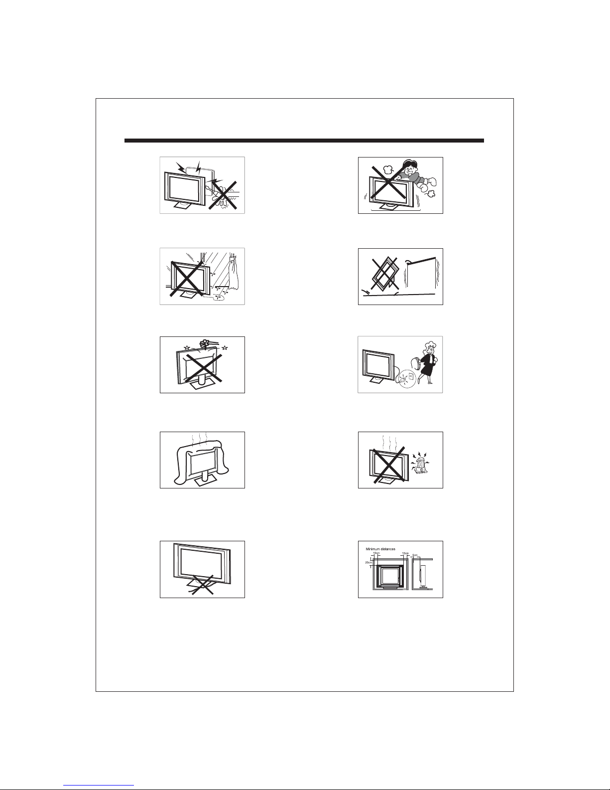
SAFETY AND WARNINGS
High voltages are used in the operation of this television
receiver. Do not remove the cabinet back from your set.
Refer servicing to qualified service personnel.
To prevent fire or electrical shock hazard, do not expose
the television receiver to rain or moisture.
Do not drop or push objects into the television cabinet
slots or openings. Never spill any kind of liquid on the
television receiver.
Do not block the ventilation holes in the back cover.
Adequate ventilation is essential to prevent failure of
electrical components.
Never stand on, lean on, or suddenly push the television or
its stand. You should pay special attention to children.
Serious injury may result if it falls.
Do not place your television on an unstable cart, stand,
shelf or table. Serious injury to an individual , and damage
to the television, may result if it falls.
When the television receiver is not used for an
extended period of time, it is advisable to disconnect
the AC power cord fromthe AC outlet.
Avoid exposing the television receiver to direct sunlight
and other sources of heat. Do not stand the television
receiver directly on other products which give off heat,
e.g. video cassette players and audio amplifiers. Do not
place naked flame sources, such as lighted candles on
the television.
Do not trap the power supply cord under the television
receiver.
Dim:515*320mm(
If the television is to be built into a compartment or similar
enclosure, the minimum distances must be maintained. Heat
build-up can reduce the service life of your television, and
can also be dangerous.
-3-
Page 5
SAFETY AND WARNINGS
Thank you very much for purchasing this TV. To enjoy
your product from the very beginning, read this manual
carefully and keep it handy for easy reference.
INSTALLATION
Locate the TV in the room where light does not strike
the screen .
directly
Total darkness or a reflection on the picture screen can
cause eyestrain. Soft and indirect lighting is recommended
for comfortable viewing.
Allow enough space between the TV and the wall to
permit ventilation.
Avoid extremely warm locations to prevent possible
damage to the cabinet or premature component failure.
This TV can be connected to AC 100-240 Volts. 50/60 Hz.
Never connect to a DC supply or any other power supply.
Do not cover the ventilation openings when using the TV.
CAUTION
Never tamper with any components inside the TV, or any
other adjustment controls not mentioned in this manual.
All LCD-TVs are high voltage instruments. When you
clean up dust or water drops on the LCD PANEL or
CABINET, the power cord should be pulled out from the
receptacle, then wipe the TV with a dry soft cloth. During
thunder and lighting, unplug the power cord and antenna
cord to prevent damage to your TV. All repairs to this TV
should only be performed by qualified TV service personnel.
Earthing connection--- The apparatus shall be connected
to MAINS socket outlet with a protective earthing connection
MAINS plug or appliance coupler of the apparatus is used
as disconnect device, it should remains readily operable
television reception, which can be determined by turning
the equipment off and on, the user is encouraged to try to
correct the interference by one or more of the following
measures:
- Reorient or relocate the receiving antenna.
- Increase the separation between the equipment and receiver.
- Connect the equipment into an outlet on a circuit different
from that to which the receiver is connected .
-Consult the dealer or an experienced radio TV technician
for help.
Shield cables must be used with this unit to ensure
compliance with the Class B FCC limits.
Warning: Change or modifications to this unit not expressly
by the part responsible for compliance could void the user 's
authority to operate the Equipment.
NOTE:
This equipment has been tested and found to comply with
the limits for a Class B digital device, pursuant to Part 15
of the FCC Rules. These limits are designed to provide
reasonable protection against harmful interference in a
residential installation. This equipment generates, uses, and
can radiate radio frequency energy and, if not installed and
used in accordance with the instructions, may cause harmful
interference will not occur in a particular installation. If this
equipment does cause harmful interference to radio or
-4-
Page 6
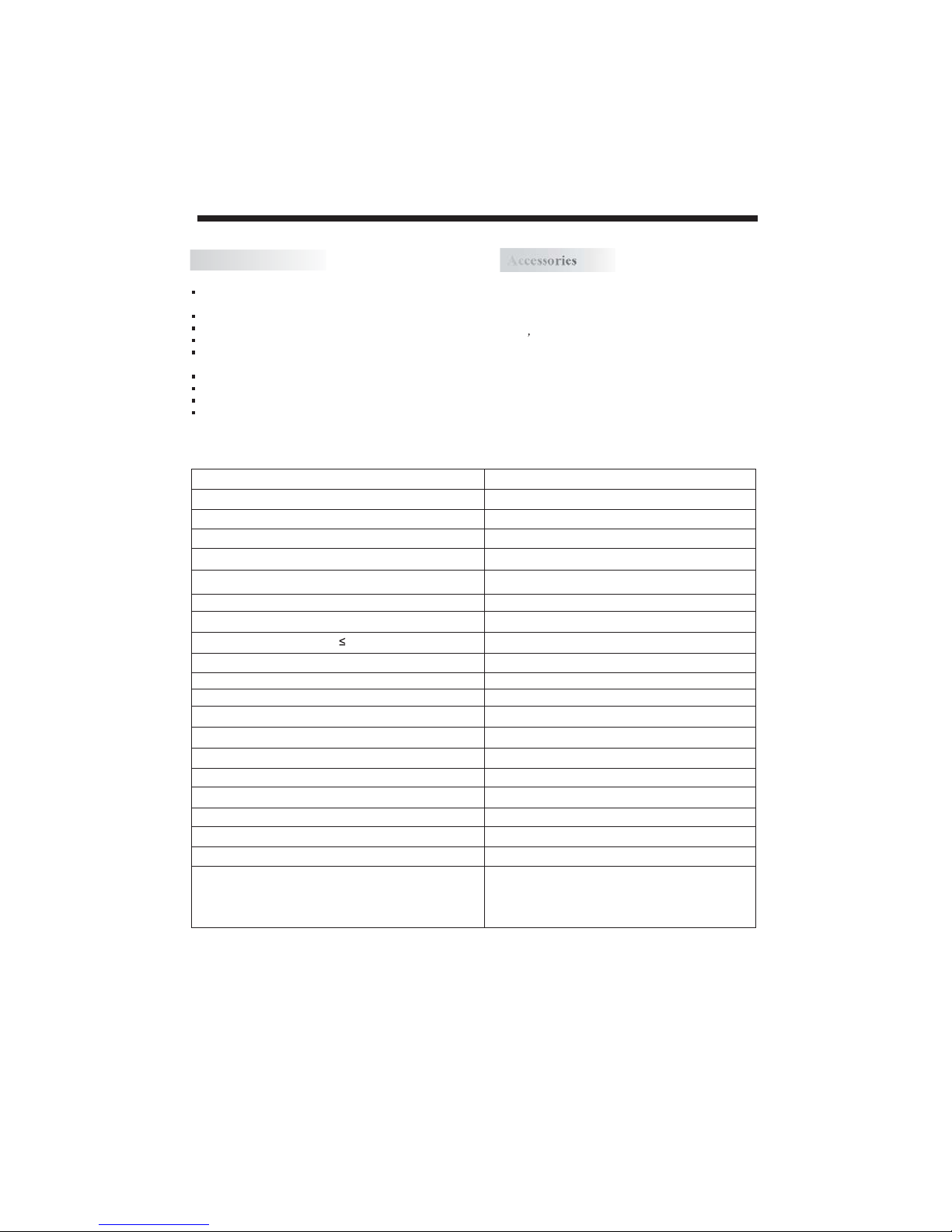
Main features
Accessories
Accessories
INTRODUCTION
1920 x 1080 native resolution for Full-HD (1080p)
performance
Integrated ATSCTV tuner for HDTV broadcast reception
High brightness provides a vivid and brilliant picture
Deeper blacks and brighter whites with high contrast
Wide Screen aspect ratio (16:9) for a complete home
theater experience
HDMI input for true digital connection
VGA port for connection to PC
Built-in stereo speaker system
Full-function Remote Control
AC Power Cord.........................
Infrared Remote Control...........
User s Manual ........................
Battery(AAA).......................... 2
Main parameter
Viewing Picture Size(diagonal) 42inch
Resolution: 1920x1080
Aspect Ratio: 16:9
TV System:
Video Signal System:
Receiving Channel:
Power consumption: 300W
Input Power Voltage:
Audio Output Power(THD 7%): 2x8W
Rear High-Definition Multimedia Interface(HDMI) Input x 2
Rear S-Video Input x 1
YCb(Pb)Cr(Pr) Input x 1
Analog Audio Output x 1Rear
Rear Coaxial SPDIF Output x 1
Analog RGB(VGA) Input x 1
Rear Composite Video Input x 1
Rear Audio Input x 3
Side Composite Video Input x 1
Side HEAD PHONE Output x 1
Rear Composite Video Output x 1
Horizontal definition(TV line)
1
1
1
ATSC Digital system and NTSC Analog system
NTSC/PAL/SECAM
Cable :1-135/ Air: 2-69(ATV&DTV)
AC 100V-240V 50/60Hz
Composite Video Input >=350
Video Input >=400
YCb(Pb)Cr(Pr) >=400
-5-
Page 7
INSTALLATION
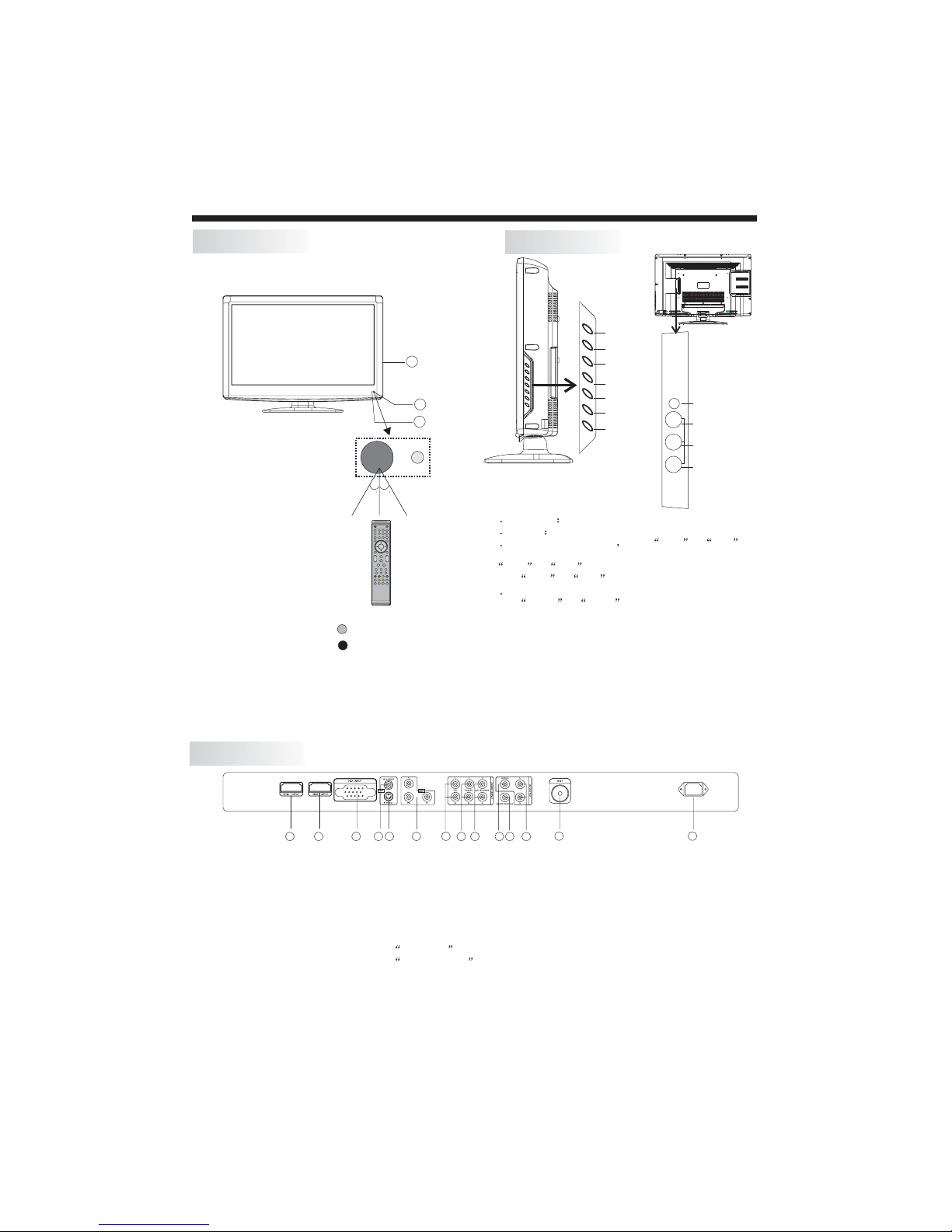
Front panel
30 30
1 2 3
4 5 6
7 8 9 0
+
+
CH
VOL
_
_
1: Remote control sensor.
2: Indicator LED: GREEN POWER ON.
RED STANDBY.
3: Key board
Side panel
SOURCE
MENU
3
1
2
1 SOURCE
2MENUD
3 CH+/CH-:
change the channel up and down.In MENU mode, press
CH+ or CH- to select items .
press CH+ or CH- to
4 VOL+/VOL-:
press VOL+ or VOL- to
selected.
STANDBY :
5.
from STANDBY mode. Press it again to turn the set
back to STANDBY.
6.HEADPHONE OUTPUT
7.VIDEO INPUT
8.AUDIO INPUT-L
9.AUDIO INPUT-R
In TV mode press CH+ or CH- to
CH+
CH-
VOL+
VOL-
STANDBY
Display the input source menu.
isplay main MENU.
Adjust sound level.In MENU mode,
turn on the TV.
adjust the item that you
HEADPHONR
HEADPHONE
VIDEO
Video
AV2
L
L
R
R
In standby mode,
Press this button to turn the unit ON
REAR AV Connection
2
1
8 9
10 11 12
7
2 3 54
1
1. HDMI1 INPUT
2. HDMI2 INPUT
3. VGA INPUT
4. AV1 INPUT
5. S-VIDEO INPUT
Note:
1.AV1 and S-VIDEO share one audio channel.
2. When HDMI1 port get DVI signal, the PC Audio channel will change to receive the audio from HDMI1 port
3. When HDMI2 port get DVI signal, the YPbPr Audio channel will change to receive the audio from HDMI2 port.
4.AV OUTPUT :
When the source are AV1,AV2(side) S-VIDEO,ATV,theAV OUTPUT Channel reproduce the input
signals accordingly
6
6. YPbPr INPUT
7. PC AUDIO INPUT
8. YPbPr AUDIO INPUT
9. AV1/S-VIDEO AUDIO INPUT
10. VIDEO OUTPUT
13 14
11. OUTPUTSPDIF
12. AUDIO OUTPUT
13. ANT
14. AC POWER INPUT
-6-
ACINPUT
100-240V~50/60Hz
Page 8
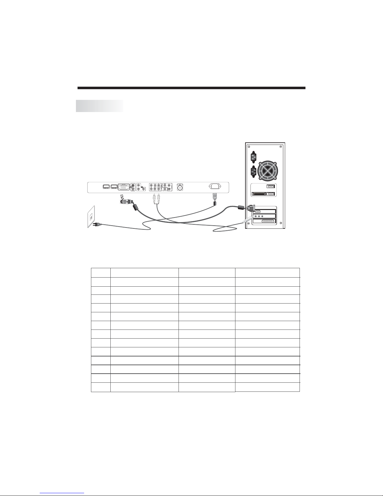
PC
STEPS:
Be sure both the TV and computer are set to Power off.
1.Connect VGA and audio cable.
2.Connect the power cord.
3.Power on the TV, switch to VGA mode.
4.Power on the VGA.
This sequence is very important.
2
1
Power cord
PC Audio
PRESET MODE
ACINPUT
100-240V~50/60Hz
INSTALLATION
VGA cable
RESOLUTION
1
2
3
4
5
6
7
8
9
10
11
12
13
720*400
640*480
640*480
640*480
800*600
800*600
800*600
800*600
1024*768
1024*768
1024*768
1280*1024
1280*1024
V.Freq.(Hz) H.Freq.(KHz)
70
60
72
75
56
60
72
75
60
70
75
60
75
-7-
31.47
31.47
37.86
37.50
35.156
37.88
48.08
46.88
48.36
56.48
60.02
63.98
80.00
Page 9
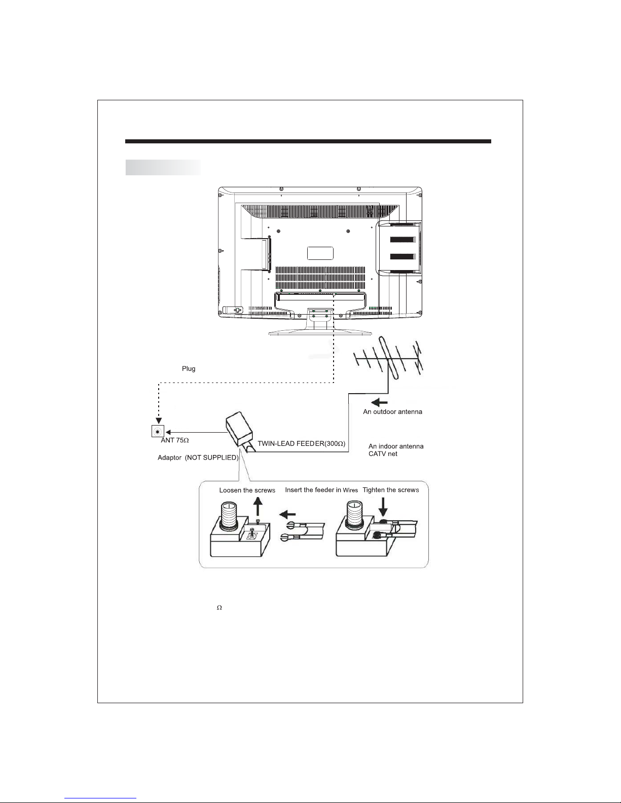
ANTENNA
INSTALLATION
Note:
Aerial connections:IEC(female).
Input impendance:75 unbalanced.
-8-
Page 10
INSTALLATION
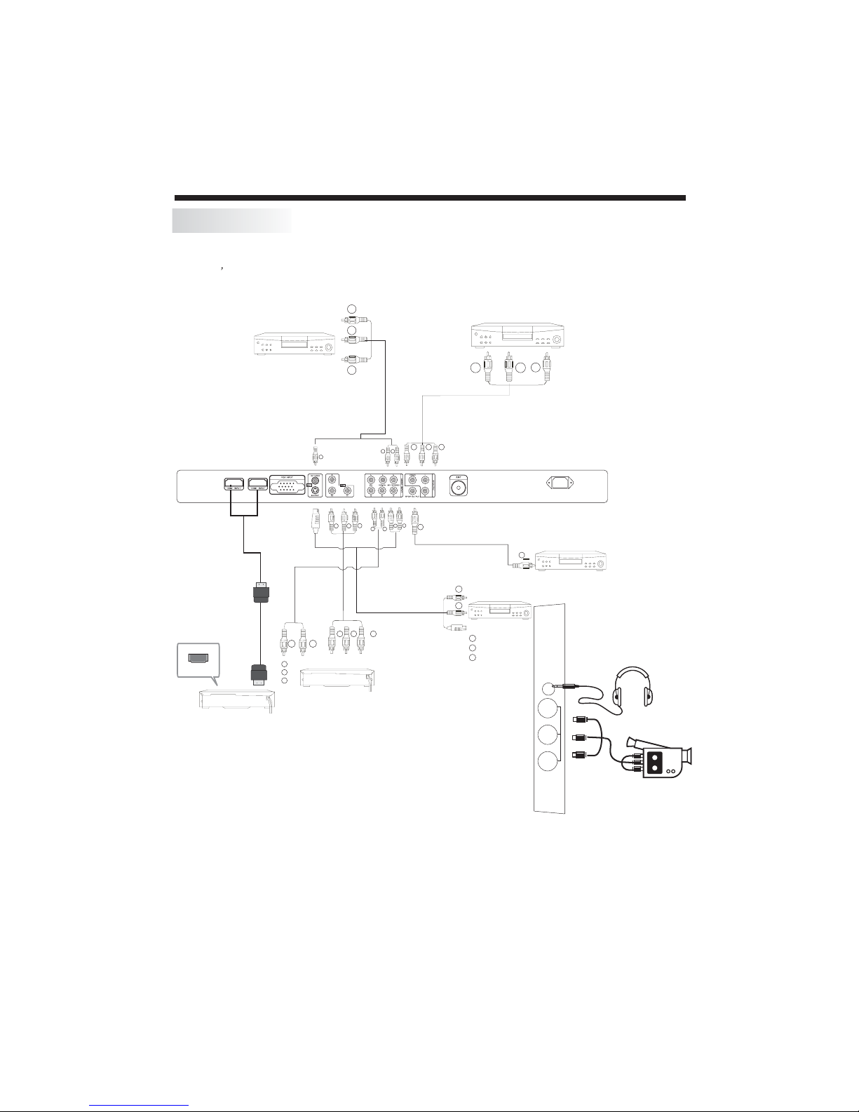
AV EQUIPMENT
This TV provides two groups of AV ,one S-Video,one group of YPbPr for convenient connection
to VCR,DVD or other video equipment,three group of HDMI for HD signal input Please refer to
the owner s manual of the equipment to be connected as well.
You can use the input terminals on TV set rear as follows.
To audio
R
Output
W
To video
Y
output
R
Y
W R
W
R
R
B
W
G
R
B
R
Y
To audio
outputs
To s-video
output
HDMI
With VIDEO
terminal
VIDEO EQUIPMENT
2
1
Y
R
W
VIDEO EQUIPMENT with YPbPr
R
Pr
G
Y
Pb
B
G
With VIDEO Input Terminal
W R
To audio Input
W
From Coaxial SPDIF
output
R
with S-video
Terminal
W
VIDEO EQUIPMENT
Y/C
Black (s-video)
W
White(audol L)
Red(audio R)
R
Y
TO
Input
ACINPUT
100-240V~50/60Hz
with SPDIF Input
terminal
Y
VIDEO RECORDER
HEADPHONE
VIDE
O
It can be connected to the following appliances: VCR, multi disc player, DVD, camcorder, video game or stereo
system, etc.....
YPbPr can support these video fomats:480i,576i,480p,576p,720p,1080i,1080p.
Video
AV2
L
R
-9-
Page 11

3
6
9 0
ENTER
S.M
P.M
ASPECT
FAV EPG
PAGE U P PA GE DO WN
MUTE
RECALL
SOURCE
TV DISPLAY
HDMI
EPG
11
12
13
14
15
+
CH
_
16
17
18
19
22
23
24
29
30
1
POWER
1
MENU
2
5
4
7
8
2
3
4
5
6
7
EXIT
+
VOL
_
MTS/SAP
8
9
10
20
21
25
26
27
28
SLEEP P.G CC
CH LIST
TV AV SVIDEO
YPbPr VGA
Insert Batteries Into the Remote Control
12
1. Remove the battery cover.
2. Inserting the 2 AAA 1.5V batteries making sure the
polarity (+ or -) of the batteries matches the polarity
marks inside the unit.
3. Mount the battery cover.
Replace with new batteries when the TV set begins
to show the following symptoms:
Operation is unsteady or erratic. Sometimes the TV
set does not function with Remote Control Unit.
Remark:
1) Alkaline Battery Recommended.
2) Remove batteries when they are exhausted or if the
remote control is not to be used for long time.
3
REMOTE CONTROL
POWER
1:
To set theTV standby or on.
NUMBER KEY
2: :
For direct access to program.
MENU
3:
To display TV menu or to return to the previous menu.
CURSOR
4:
To move withinthe menu.
EXIT
5:
Used to exit menu.
VOL+/-
6:
To adjust soundlevel.
.M
7: P
To switch picturemode.
MTS/SAP
8:
Switch the sound stereo, SAP and mono.
SLEEP
9:
Set time to turn off the TV.
P.G
10:
Setting the Parental Control level control.
MUTE
11:
To disable orenable the sound.
RECALL
12:
To access thepreviously viewed program.
SOURCE
13:
To display orexit TV input source menu.
ENTER
14:
Confirms selection.
TV DISPLAY
15:
Displays/removes the program Information
S.M
16:
To switch soundmode.
CH+/CH-
17:
To access thenext or previous Program.
ASPECT
18:
To change pictureaspect .
CC
19:
Enable or disable the CC function.
CH LIST:
20:
Usedtodisplaythechannellist
21: :
FAV
Used to access your favourite channels in digital TV mode.
22: :
EPG
Display all the information of DTV programs.
23.
HDMI:
Hot key directly go to HDMI source.
24:
SVIDEO:
Hot key directly go to SVIDEO source.
25:
TV:
Hot key directly go to TV source.
26:
AV:
Hot key directly go toAV source.
27:
YPbPr:
Hot key directly go to YPbPr source.
28:
VGA:
Hot key directly go to VGA source.
29:
PAGE DOWN/PAGE UP
In EPG mode, use this key to page up/down the EPG
information.
30. Reserved keys
COLOR KEYS:
-10-
Page 12

OPERATION
1. PICTURE MENU
The first item of the MENU is PICTURE MENU.
You can adjust picture effect here, such as contrast,
brightness, etc.
Press to select, press to adjust, press MENU
to exit.
Timer Setup
Audio
Picture
Picture mode
Contrast
Brightness
Color
Tint
Sharpness
Color Temp.
Select Adjust
Note:
If you want to adjust contrast, brightness, color,
and sharpness , the picture mode must return to
personal status.
Standard
Normal
P.G
Menu Exit
Channel
50
50
50
0
50
2.AUDIO menu
The second item of the MENU is AUDIO MENU.
You can adjust sound here.
Press to select, press to adjust, press MENU
to exit.
Picture
Audio
Timer Setup Channel
Sound mode
Bass
Treble
Balance
Surround
AVC
SPDIF Type
Audio language
Select Adjust
Note:
The item of Audio language is available in ATSC
program.
Standard
Off
Off
PCM
English
Menu Exit
P.G
50
50
50
3.TIMER MENU
The third item of the MENU is TIMER MENU.
You can adjust time here.
Press to select, press to adjust, press MENU
to exit.
Picture
Audio
Timer
Sleep timer
Time zone
Daylight SavingTime
Clock
Select Adjust
1).Sleep Timer: adjust this item, you can set the
sleeptimer.
Note:
The item of Time zone, the item of Daylight Saving
Time and the item of Clock are available in ATSC
program
P.G
Setup
Off
Pacific
Off
1999/12/31 04:03PM
Menu Exit
Channel
4. SETUP MENU
The forth item of the MENU is SETUP MENU.
You can setup system here.
Press to select, press to adjust, press MENU
to exit.
Picture
Audio
Menu language
Transparency
Aspect
Noise Reduction
Advanced
Closed caption
XVS
Restore Default
Select Adjust
Timer
Setup
P.G
English
On
16:9
Weak
Off
Menu Exit
Channel
Note:
Restore Default: Reset all the settings to default
value.
-11-
Page 13

OPERATION
1). Advanced: In PC Mode is available.
Press button to select Advanced item , Press
button, the screen will display as follow:
AudioPicture
H-pos
V-pos
Clock
Phase
Auto
Select Adjust
(1).H-Pos:Adjust the horizontal position of the screen.
(2).V-Pos:Adjustthe vertical position of the screen.
(3).Clock: Fine tune the screen width.
(4).Phase: Fine tune the phase of the screen. Usually
don`t adjust this item.
(5).Auto: Auto adjust to fitthe screen.
Timer
Setup
P.G
Menu Exit
Channel
50
50
50
50
2). Closed Caption: switch close caption mode.
Press button to select Closed Caption item,
Press button, the screenwill display as follow:
Audio
Picture
CC Mode
Basic Selection
Advanced Selection
Option
Select Adjust
Timer
Setup
P.G
Off
CC4
Service 3
Menu Exit
Channel
5. MENUP.G
The fifth item of the MENU is MENU.
You can setup here.
Press to select, press to adjust, press MENU
to exit.
Parent Control: input the password, it will go into
Parental Control
is 6666.
5.1 .Input the correct password ,the screen will display
as follow:
1). Change Password: Press button, the screen will
display as follow:
Parental Control
Audio
Picture
Enter password
Select Adjust
Picture Audio
Change password
P.G switch
US
Canada
RRT setting
Reset RRT
Select Adjust
menu. Factory default password
Timer
Timer
Setup
Setup
PG
.
----
P.G
Menu Exit
P.G
On
Menu Exit
Channel
Channel
(1):Advanced Selection: only ATSC program is available.
(2):Option:Used to edit CC font.
Press button, the screen will display as follow:
AudioPicture
Timer
Mode
Font style
Font size Default
Font Edgestyle Default
Font Edgecolor Default
FG color Default
BG color Default
FG opacity Default
BG opacity Default
Select Adjust
NOTE: Only ATSC program is available.
Setup
P.G
Custom
Default
Menu Exit
Channel
Timer
Setup
----
----
Menu Exit
Audio
Picture
New password
Confirm password
Select Adjust
1).New Password: Input the new password
2).Confirm Password: Input the new password again
-12-
Channel
P.G
Page 14

OPERATION
5.2 PG
. switch:
When the switch is ON, the below
options can be adjusted.
Parental Control
5.3 US: Press button, the screen will display as
follow:
Picture Audio
TV
MPAA
Select Adjust
1):TV: Press button, the screen will display as
follow:
Audio
Picture
ALLFVVS L D
TV-Y
TV-Y7
TV-G
TV-PG
TV-14
TV-MA
Block Press ENTERto lock orunlock
Select Adjust
Rating Content
TV-Y(All
children)
TV-Y7(Directto
order children)
Suggested
TV-G(General
age
audience)
TV-PG(Parental
Guidance
suggested)
TV-14(Parents
strongly
cautioned)
TV-MA(Mature
audience only)
And use ENTER key to switch lock/ unlock
feature.
Control
FV
(Fantasy
violence)
Timer
Timer
TV rating
X
Setup
Setup
V
(Violence)
X
X
X
P.G
X
Menu Exit
P.G
Menu Exit
Content
S
(Sexual
situation)
X
X
X
Channel
Channel
L
(Adult
language)
X
X
X
Parental
D
(Sexually
suggestive
dialog)
X
X
2).MPAA:switchthe movie-rating control level: N/A,
G, PG, PG-13,R,NC-17,X.
Rating
Description
G General audiences, AllAges admitted
Parental Guidancesuggested. Some materialmay not be
PG
Suitable forchildren.
Parents stronglycautioned. Some material.may be
PG-13
Age
5.4 Canada: Press button, the screen willbe
displayed as follow:
1): Canada English: switch the english rating control
level:E,C,C8+,G,PG,14+,18+.
Rating
E Exempt: Includesnews, sports, documentsand other information
C Children: Intendedfor younger childrenunder the ageof 8 years.
C8+ Children over 8years old: Containsno portrayal ofviolence as the
G General: Consideredacceptable for allage groups, Appropriate
Age
PG Parental Guidance: Intended fora general audience,but may notbe
14+ Over 14Years: Couldcontain themes whereviolence is oneof the
18+ Adults: Intended forviewers 18 yearsand older andmight contain
Inappropriate forchildren under 13.
Restrict. Under17 requires accompanyingparent or adult
R
guardian(age variesin some jurisdictions)
NC-17
No one 17 andunder admitted.
X is an orderrating that isunified with NC-17but may be
X
encoded inthe data oforder movies.
Picture
Canada English
Canada French
Select Adjust
Audio
Timer
Setup
P.G
14+
E
Menu Exit
Channel
Description
programming: talkshows, music videos,and variety programming.
Pays carefulattention to themesthat could threatentheir sense of
securityand well-being.
preferred, acceptable,or only wayto resolve conflict;nor encourage
children toimitate dangerous actswhich they maysee on thescreen .
viewing forthe entire family, contains very littleviolence, physical,
verbal oremotional.
suitable foryounger children (underthe age of8) because itcould
contain controversialthemes or issues.
dominant elementsof the storyline,But itmust be integralto the
devel opmentof plot orcharacter. Language usage couldbe profane
and nudity present withinthe context oftheme.
depictions of violence, which while relatedto the developmentof
plot, character or themes,are intended foradult viewing. Could
contain graphiclanguage and portrayalsof secretary andnudity.
-13-
Page 15

OPERATION
2).Canada French: switch the French-rating control
level: E, G,8ANS+,13 ANS+,16ANS+,18ANS+.
Rating
Description
E Exempt programming
G General :Allages and children,contains minimal directviolence,
but maybe integrated intothe plot ina humorous orunrealistic
manner .
8ans+ General butinadvisable for youngchildren :May beviewed by a
Age
wide publicaudience, but couldcontain scenes disturbingto
children under8 who cannotdistinguish between imaginaryand
real situations.Recommended for viewingwith parent.
13ans+ Over 13 years:Could contain scenesof frequent violentscenes
and intense violence.
16ans+ Over 16 years:Could contain frequentviolent scenes andviolence.
18ans+ Over 18 years:Only for adultviewing. Could containfrequent
violent scenes and extremeviolence.
5.5 RRT Setting: inATSC digital TV mode, it could be
adjusted
5.6 Reset RRT: Press button, the screen will be
displayed as follow:
Picture
Audio
Timer
Are yousure?
NO
Select Adjust
Setup
YES
P.G
Menu Exit
Channel
6. Channel MENU
The sixth item of the MENU is CHANNEL MENU.
You can adjust digital and analoge TV channel here .
Press to move, press to adjust.
Timer
Setup
P.G
Cable
2-1
Menu Exit
Channel
Audio
Picture
Air/cable
Auto Scan
Favorite
Show/Hide
Channel NO.
Channel Lable.
DTV signal :
Select Adjust
1). Air/Cable: select air TV signal or cable TV signal.
2). Auto Scan: If it's the first time using the TV, it
should scan all the TV channels first,
press the button to confirm, you will see below
menu :
Picture
Audio
Timer
Start to scan
Select Adjust
A: Start to Scan: press the button to confirm, you
will see below menu which indicates auto search is
in process.
Audio
Picture
3). Favorite: Press button to choose/delete the
favorite channel .
4). Show/Hide: Press button to display or hide
currently channel.
5). Channel NO. :Display the currently channel number.
6). Channel Lable: Press button to edit currently
channel name.
7). DTV Signal: Display DTV signal intension. It can't be
selected and adjusted.
Timer
RF CH: 4
FOUND: 0
Select Adjust
Setup
Setup
P.G
Menu Exit
P.G
Menu Exit
Channel
Channel
-14-
Page 16

Trouble shooting
Trouble phenomenon Symptom
Picture Audio
Snow Noise
Ghost
Interference
Normal Picture
No picture Mute
No colour Normal audio Colour control
Normal audio
Noise
Mute
Inspection Check
antenna position, direction
or connection
antenna position, direction
or connection
electronic equipment,car/
motorcycle,fluorescent light
Volume(check if mute is
activated or if the audio system
connections are not correct)
Power cord is not inserted
Power switch is not opened
Contrast and brightness/volume
setup
Press standby key on the remote
control for inspecting
Picture
breaking up
No colour
The LCDTV panel is built with very high precision technology giving you fine picture details
in vibrant color. Occasionally, a few non-active pixels may appear on the screen as a fixed
point of red, green, blue, black or white. Please note this does not affect the performance of
the product.
Normal audio
or weak
Noise
-15-
retune channel
TVsystem
Page 17

-1-
Page 18

-2-
Page 19

Dim:515*320mm(
-3-
Page 20

-4--4-
Page 21

42
300
-5-
Page 22

30 30
1 2 3
4 5 6
7 8 9 0
+
VOL
_
Panel lateral
SOURCE
MENU
CH+
3
1
2
+
CH
_
CH-
VOL+
VOL-
STANDBY
HEADPHONE
Video
L
R
HEADPHONR
VIDEO
AV2
L
R
2
1
2 3 54
1
1.
2.
3.
4.
5.
6.
7.
8.
9.
10.
ACINPUT
100-240V~50/60Hz
8 9
10 11 12
7
6
13 14
11.
12.
13.
14.
-6-
Page 23

PC
2
1
ACINPUT
100-240V~50/60Hz
1
2
3
4
5
6
7
8
9
10
11
12
13
720*400
640*480
640*480
640*480
800*600
800*600
800*600
800*600
1024*768
1024*768
1024*768
1280*1024
1280*1024
70
60
72
75
56
60
72
75
60
70
75
60
75
-7-
31.47
31.47
37.86
37.50
35.156
37.88
48.08
46.88
48.36
56.48
60.02
63.98
80.00
Page 24

-8-
Page 25

R
W
HDMI
Y
R
Y
Y
2
1
G
W R
W
R
R
B
W
Y
R
W R
W
Y
Y
R
W
G
R
B
R
W
R
Pr
G
Y
Pb
B
Y
W
R
HEADPHONE
Video
AV2
L
R
-9-
Page 26

3
6
9 0
SOURCE
MUTE
RECALL
11
12
13
1
POWER
1
MENU
2
5
4
7
8
2
3
14
4
ENTER
5
6
7
EXIT
+
VOL
_
MTS/SAP
TV DISPLAY
S.M
+
CH
_
P.M
ASPECT
8
9
10
20
21
25
26
27
28
SLEEP P.G CC
FAV EPG
CH LIST
TV AV SVIDEO
PAGE U P PA GE DO WN
YPbPr VGA
HDMI
EPG
12
15
16
17
18
19
22
23
24
29
30
3
-10-
Page 27

Picture Audio
Picture mode
Contrast
Brightness
Color
Tint
Sharpness
Color Temp.
Picture
Sound mode
Bass
Treble
Balance
Surround
AVC
SPDIF Type
Audio language
Select Adjust
Timer Setup
Select Adjust
Audio
Timer Setup Channel
Standard
Normal
Standard
Off
Off
PCM
English
Menu Exit
P.G
Menu Exit
P.G
P.G
Off
Pacific
Off
Menu Exit
P.G
English
On
16:9
Weak
Off
Menu Exit
Channel
Channel
Channel
Audio
Timer
Setup
Picture
Sleep timer
50
50
50
0
50
Time zone
Daylight SavingTime
Clock
1999/12/31 04:03PM
Select Adjust
50
50
50
Picture
Audio
Menu language
Transparency
Aspect
Noise Reduction
Advanced
Closed caption
XVS
Restore Default
Timer
Setup
Select Adjust
-11-
Page 28

H-Pos
V-Po s
Clock
Audio
Picture
H-pos
V-pos
Clock
Phase
Auto
Select Adjust
P.G
Menu Exit
Channel
50
50
50
50
Picture
Enter password
Audio
Setup
Timer
----
Channel
P.G
Setup
Timer
Phase
Auto
Audio
Picture
CC Mode
Basic Selection
Advanced Selection
Option
Select Adjust
1
2
AudioPicture
Mode
Font style
Font size Default
Font Edgestyle Default
Font Edgecolor Default
FG color Default
BG color Default
FG opacity Default
BG opacity Default
Select Adjust
Setup
Setup
----
----
Menu Exit
P.G
On
Menu Exit
P.G
Menu Exit
Channel
Channel
Select Adjust
Audio
Picture
Change password
P.G switch
US
Channel
P.G
Setup
Timer
Off
CC4
Service 3
Menu Exit
P.G
Custom
Default
Menu Exit
Channel
Setup
Timer
Canada
RRTsetting
Reset RRT
Picture
New password
Confirm password
Timer
Select Adjust
Audio
Timer
Select Adjust
-12-
Page 29

Picture
Audio
TV
MPAA
Select Adjust
Timer
Setup
P.G
X
Menu Exit
Channel
G
PG
PG-13
R
NC-17
X
Audio
Picture
TV-Y
TV-Y7
TV-G
TV-PG
TV-14
TV-MA
Block Press ENTERto lock orunlock
Timer
TV rating
ALLFVVS L D
Select Adjust
X
Picture Audio
Canada English
P.G
Menu Exit
X
X
X
Channel
X
X
X
X
X
Setup
X
X
X
Canada French
Select Adjust
Timer
Setup
P.G
14+
E
Menu Exit
Channel
-13-
Page 30

Picture Audio
Start to scan
Timer
Setup
P.G
Channel
Picture
Audio
Select Adjust
AudioPicture
Air/cable
Auto Scan
Favorite
Show/Hide
Channel NO.
Channel Lable.
DTV signal :
Select Adjust
Timer
Are yousure?
NO
Timer
Setup
Setup
Setup
Menu Exit
P.G
Channel
Select Adjust
Audio
Picture
Channel
P.G
Timer
RF CH: 4
FOUND: 0
YES
Select Adjust
Menu Exit
Menu Exit
P.G
Channel
Cable
2-1
Menu Exit
-14-
Page 31

-15-
Page 32

Page 33

 Loading...