

Page 1

Ethos Landscape & Portrait
Remote Control
- Log, Pebble & Driftwood Effect
- Inset Live Fuel Effect Radiant Convector Fire
Installation and
Users Instructions
These instructions should be read by the
installer before installation and then should be
handed to the end user when the installation
is complete.
This is an official requirement and is the
responsibility of the fitter of this
appliance.
Having installed the appliance, the installer
should take the necessary steps to ensure
that the user fully understands how to operate
the appliance and is also made aware of the
fire’s basic cleaning and maintenance
requirements.
Page 2

Page 3

SECTION PAGE
Notes for the Installer and End User 4
Installation Requirements 5
Installation Procedure 7
Installation - Class One Unlined Chimney 8
Installation - Class One Flue with Flexible Liner 9
Installation - False Drywall Chimney Breast & Twin Wall Flue 10
Installation - Slips Kit 12
Installation - Clip-on surrounds 13
Commissioning 15
Technical Data 17
Replacement Parts 17
Trouble Shooting (GAS SAFE Engineer Only) 18
User Instructions 20
Cleaning and Maintenance 25
Log Layout Instructions 26
Pebble & Driftwood Layout Instructions 28
Trouble Shooting (User) 30
Guarantee 30
CONTENTS
3
Page 4

This appliance has been designed, tested and manufactured to EN613 with references to British Standard BS
7977-1:2009 Class 1 & 2 relating to Radiant Convector Gas Appliances and
must be installed by a qualified Gas
S
afe Registered Installer in accordance with the Gas Safety (Installation and use) regulations 1994 and all other
r
elevant standards.
This appliance is intended for use on a gas installation with a governed meter.
T
his appliance must be connected in accordance with the National Regulations. The appliance must be sealed
into a non-combustible fireplace whose only opening must be through a Class I (7” or 175mm diameter) or Class
II (5” or 125mm diameter) chimney / flue of at least three metres in height.
Before installation, ensure that the local conditions, (identification of gas type and pressure) and the adjustment
o
f the appliance are compatible. Never place combustible material directly in front of this appliance. Floor
covering such as carpet is acceptable but must be a minimum of 300mm from the incandescent flame.
NOTES FOR THE INSTALLER AND END USER
4
Fig. 1
3
00mm825mm
E
thos Landscape
Ethos Portrait
7
47mm Box Width
5
13mm
4
58mm
(
Box Height)
300mm825mm
747mm Box Width
669mm
614mm
(Box Height)
Page 5
NOTES FOR THE INSTALLER AND END USER
5
T
his fire is a very effective heating appliance and must be fitted against a wall of non-combustible material as
classified in BS 476-4:1970 (2007).
All parts of the appliance become hot while running and should therefore be considered to be working surfaces.
An air vent is not required for this application. Both appliances have been tested without the need for additional
air requirements.
W
e recommend that if the chimney/flue has been used for solid fuel, it is swept prior to installation of this
a
ppliance and that any flue restrictor or damper plate should be removed.
The chimney/flue must always generate a positive up draught to ensure safe operation.
The installer must then establish that all the products of combustion are entering the flue within ten minutes of
lighting from cold. This can be verified by inserting a lit smoke match into the central duct immediately above the
door. It should NOT be inserted into the left and right convector ducts.
T
his operation should be carried out before fitting the trim so no staining occurs (see ‘Spillage Test’ page 6).
A
n isolation valve must be fitted adjacent to the appliance. When closed, this will allow the complete burner and
control assembly to be disconnected for maintenance or repair in accordance with national regulations.
The gas supply should be provided by a semi rigid pipe with an 8mm diameter and should be no longer than 1.5
metres in length.
NOTE: When the gas supply pipe is passed through masonry or other brickwork always ensure that the end
of the pipe is covered to avoid any debris passing through into the appliance controls.
The appliance is fitted with an Oxygen Depletion Sensor (ODS) that monitors the room for products of
combustion. If products are detected, the ODS will automatically shut down the appliance. If this situation
arises, re-light the appliance, referring to the user instructions (page 20).
If shut down re-occurs, a qualified person must be called to thoroughly check the appliance. The spillage
monitoring system (ODS pilot) must not be put out of operation or be tampered with or adjusted by either the
installer or the user. If the unit is found to be at fault it should be replaced with the manufacturers original
replacement parts.
INSTALLATION REQUIREMENTS
This appliance must only be installed in Great Britain or Ireland.
1. This fire is a natural gas appliance and has been designed for use with the following applications:
a) Class I - Conventional brick or stone chimney as used for a solid fuel fire with a cross sectional dimension of
225mm x 225mm (9” x 9”) or a lined flue with a minimum diameter of 125mm (5”), with the fireplace components
conforming to BS1251, or a builders opening a minimum of:
Ethos Landscape - 466mm high and 757mm wide with a minimum depth of 325mm
Ethos Portrait - 622mm high and 757mm wide with a minimum depth of 325mm
to allow sufficient volume for debris collection (unlined chimney 12 dm3 and lined 2 dm3). Any permanent flue
restrictions or variable dampers are to be removed or locked in the fully open position.
The chimney should also
be swept prior to installation.
b) Class II -
An insulated flue (twin wall) having a minimum diameter of 125mm (5”) and a minimum ef
fective
overall height of 3 metres (10’).
NOTE: If the fire is to be used with an existing brick or stone chimney, a 125mm (5”) minimum diameter flue
liner conforming to BS715 may be used.
2. Care should be taken to prevent any damage being caused to surrounding soft furnishings or decoration, e.g.
many embossed vinyl wall coverings may become discoloured if placed too close to the appliance.
3. A suitable proprietary fire surround with 100°C rating may be used with a minimum clearance from hearth to
underside of shelf of 830mm, providing that the depth of shelf is 150mm or less. It is recommended that
combustible materials are not placed directly above or adjacent to this appliance.
Page 6

FLUE FLOW TEST
A flue flow test (smoke test) is carried out to check the effectiveness of the flue and to ensure that there is no
leakage into another part of the premises (including any loft), or as appropriate other adjoining premises (this is
p
articularly important where a number of chimneys combine into a multiple stack).
The flue flow test should be carried out using a suitable smoke pellet which the pellet manufacturer claims to
generate 5m
3
of smoke in 30 seconds burn time.
T
hese gas fires should have the flue flow test carried out with the appliance in position but not connected to the
gas supply so that the smoke test can be carried out with representative flue flow conditions.
A warm flue will be more effective than a cold flue. If the flue is reluctant to draw, which can be initially assessed
b
y lighting a smoke match at the intended position of the appliance flue connection, introduce some heat into the
flue for a minimum of 10 minutes using a blow torch or other means.
Other factors, such as weather conditions and a combination of materials used to construct the flue can all
influence the flue draught. The pre-heating process may require as much as half an hour before the flue behaves
s
atisfactory as a blow torch does not represent the volume of heat consistent with the normal appliance operation.
A Flue Flow Test should be checked as follows:
1. Carry out those visual checks as indicated previously, and continue only if satisfactory.
2. Establish that an adequate air supply is available for the combustion of the appliance
3. Close all doors and windows in the room that the appliance is to be installed.
4. Light a smoke pellet at the intended position for the appliance. Place the inset fire case into position.
5. The test is satisfactory if:
- there is no significant escape of smoke from the appliance position.
- there is no seepage of smoke over the length of the flue.
- smoke is discharged only from the correct terminal.
VENTILATION
No special ventilation bricks or vents are required in the room containing the appliance, providing that normal
adventitious room ventilation exists. The installer must determine this by carrying out a spillage test.
SPILLAGE TEST
To check for satisfactory clearance of products of combustion, close all doors and windows and leave the fire
burning for ten minutes. Insert a lit smoke match 15mm into the central duct above the glass door. The left and
right hand ducts are convection ducts. All the smoke must be drawn into the flue. If spillage occurs, allow a further
ten minutes and repeat the test. Should spillage still occur turn the appliance off and seek expert advice. To
continue the test: If an extractor fan is situated in the room the test should be repeated with the fan running. If
there is a connecting room with an extractor fan the test should be repeated with all the doors to that room open
and the extractor fan running.
INSTALLATION REQUIREMENTS
6
Page 7
INSTALLATION PROCEDURE
7
2 x Securing Screws
Black Internal Top Panel
Fire Box
Liners
Gas Connection
Cover Panel
Lower Controls
Heat Shield
30°
10mm
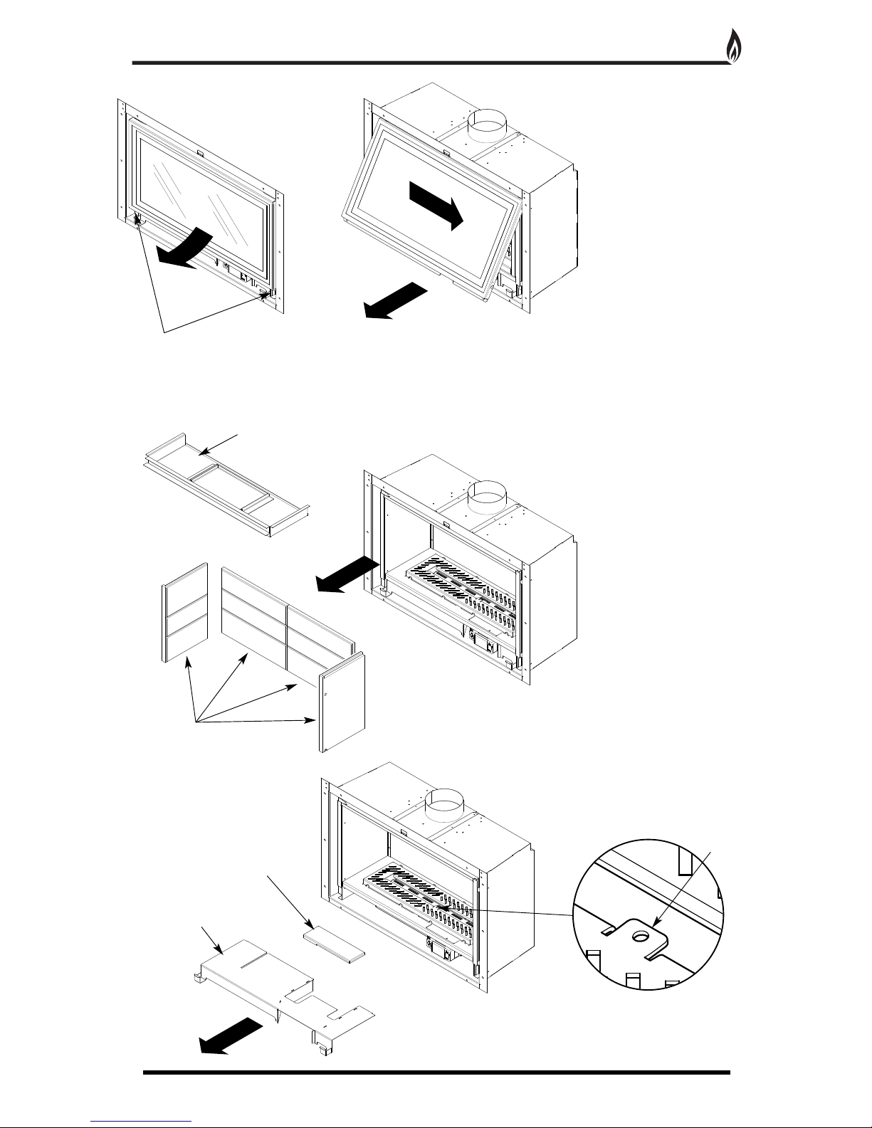
1. Remove the two screws at the bottom of the glass
door panel (Fig. 2).
2. Hinge the door upwards by approximately 30°
(Fig. 2).
3. Slide the door to the right by 10mm and remove the
door from it’s hinges (Fig. 3).
4. W
ithdraw the black internal top panel (Fig. 4).
5. Carefully remove fire box liners to avoid damage
during installation process (Fig. 4).
6. Lift of
f the black burner grille.
Note - pilot tab to be at the front on
re-assembly (Fig. 5a).
6. Remove the lower controls heat shield and gas
connection cover panel (Fig. 5).
Fig. 2
Fig. 3
Fig. 4
Fig. 5
T
ab
Fig. 5a
Page 8
INSTALLATION - Class One Unlined Chimney
8
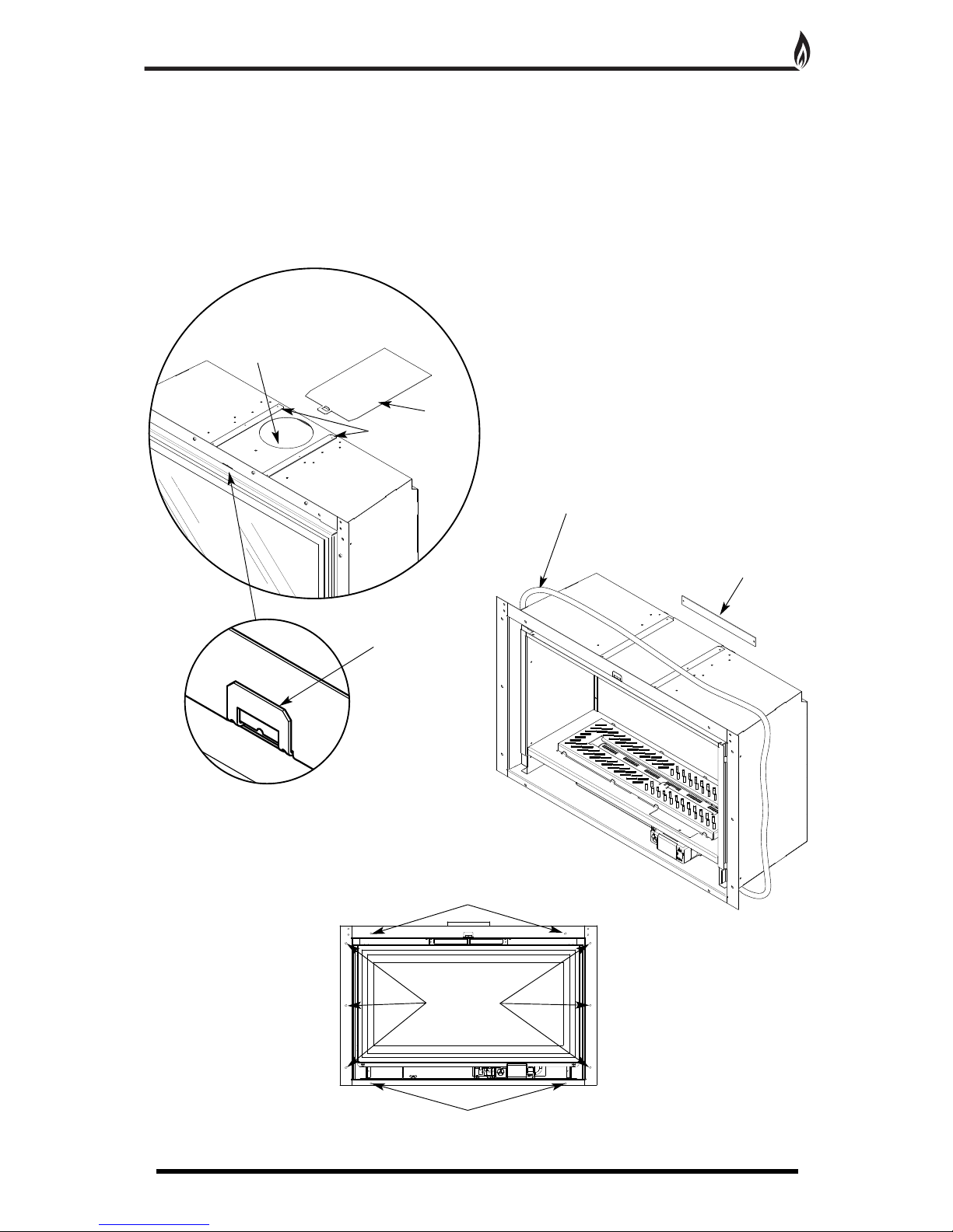
1
. Remove the 5” flue spigot adaptor and cap off the
outlet hole with the slide-in cover plate provided
(Fig. 6).
2. Bend the tab up to secure (Fig. 7).
3. Remove the rear flue outlet cover plate, this is
secured with two pozi head screws, this cover is no
longer needed and may be discarded (Fig. 8).
4. Fit the adhesive white rope seal to the back of the
fire front flange (Fig. 8)
5. Secure the fire box to the wall using the fixing holes
provided in the fire box flange (Fig. 9).
C
able
Fold Up Tab
R
unners
Blanking
P
late
Rear Outlet Cover
Plate
Adhesive White
R
ope
Fig. 8
Fig. 9
Fixing Holes
Fixing Holes
Fixing Holes
Fig. 6
Fig. 7
Page 9
INSTALLATION - Class One Flue with Flexible Liner
9
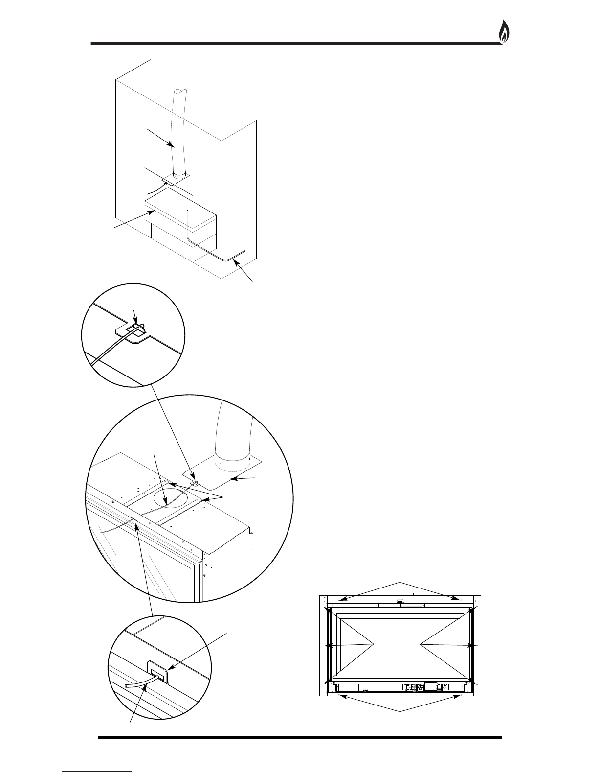
Ensure that the existing fire place lintel is made of
non-combustible material.
1
. Measure down 475mm (Ethos Landscape), 630mm
(Ethos Portrait) from the underside of the fireplace lintel
and make a mark on the wall.
2
. Construct a suitable non-combustible platform large
e
nough to sit the fire box on ensuring the top surface is
level with the mark on the wall. If the depth of chimney
breast does not facilitate a rear gas connection,
allowance must be made for the 8mm gas feed pipe to
e
nter the base of the fire box through the platform
(Fig. 10).
Under no circumstances should combustible
m
aterials such as wood be used in the construction
o
f the platform, due to the high temperatures that
the fire box reaches.
3. Insert the end of the flexible flue liner into the flue
plate ensuring that the cable is at the front and secure
with the three self tapping screws provided, then seal
around the joint using a proprietary fire cement or
mastic (Fig. 12).
4. Feed the cable provided through the hole in the flue
plate as shown.
5. Feed the cable through the hole in the top flange of
the fire box from the rear (Fig. 11).
6. Locate the front of the flue plate into the runners on
top of the fire box (Fig. 12).
7. When the flue plate is located in the runners carefully
pull the cable from the front of the fire and slide the fire
box into the opening at the same time. The flue plate
will slide through the runners and locate the flue over
the opening in the fire box (Fig. 12).
8. With the tab pulled through the slot in the flange of
the fire box, pull tight and bend the tab upwards to
secure (Fig. 13).
9. Cut of the remaining cable flush with the front of the
fire box (Fig. 13).
10. Secure the fire box to the wall using the fixing holes
provided in the fire box flange (Fig. 14).
Flexible Flue
L
iner
N
on-combustible
Platform
Cable
Fold Up Tab
Cable
Runners
Flue Plate
8mm Gas
Feed Pipe
F
eed cable through
small hole in flue plate
Fig. 10
Fig. 11
Fig. 12
Fig. 14
Fig. 13
Fixing Holes
Fixing Holes
Fixing Holes
Page 10
INSTALLATION - False Drywall Chimney Breast & Twin Wall Flue
10
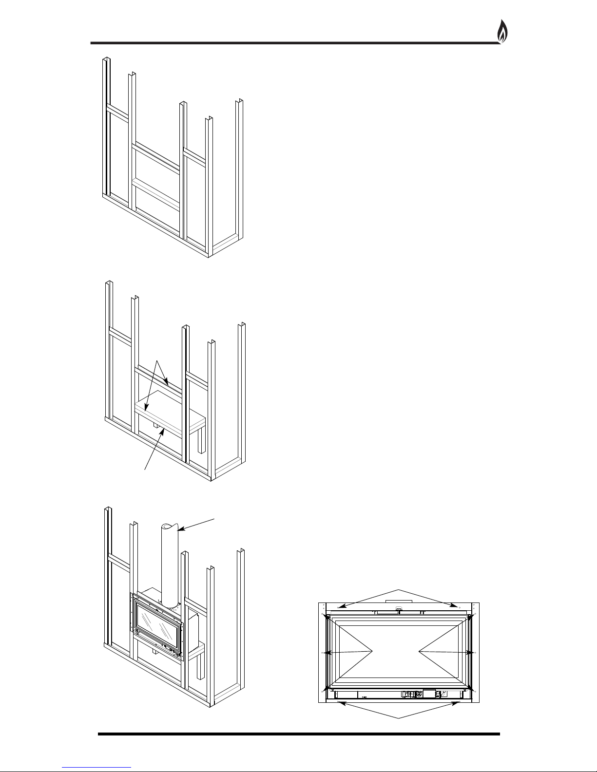
1. Construct a false chimney breast using a suitable
n
on-combustible steel frame construction kit (Fig. 15).
2. Ensure that there are two vertical steel battens
placed to allow the flange of the fire box to be screwed
to them (Fig. 15).
3
. Fix a horizontal batten at the desired height for the
fire box to sit on. Fix the second horizontal batten high
enough so that the firebox can slide into the opening
(Fig. 15).
Under no circumstances should combustible
materials such as wood be used in the construction
of the false chimney breast, due to the high
temperatures that the fire box reaches.
4. Construct a suitable non-combustible platform large
enough to sit the fire box on and level with the top of
the lower horizontal batten (Fig. 16).
Under no circumstances should combustible
materials such as wood be used in the construction
of the platform, due to the high temperatures that
the fire box reaches.
5. Slide the fire box into position and fix through the
holes in the flange into the chimney breast framework
using self drilling screws (Fig. 17).
6. Locate the twin wall flue pipe on to the flue adapter
on the top of the fire box. Drill three holes with a 3mm
bit around the flue tube and secure using the three self
tapping screws provided (Fig. 17).
7. Seal any gaps with fire cement.
8. Secure the fire box to the wall using the fixing holes
provided in the fire box flange (Fig. 18).
F
ig. 15
Fig. 16
Fig. 17
Fig. 18
S
teel Drywall Frame Kit
Non-combustible
Platform
Twin-Wall Flue
H
orizontal
Battens
Fixing Holes
Fixing Holes
Fixing Holes
Page 11

INSTALLATION - False Drywall Chimney Breast & Twin Wall Flue
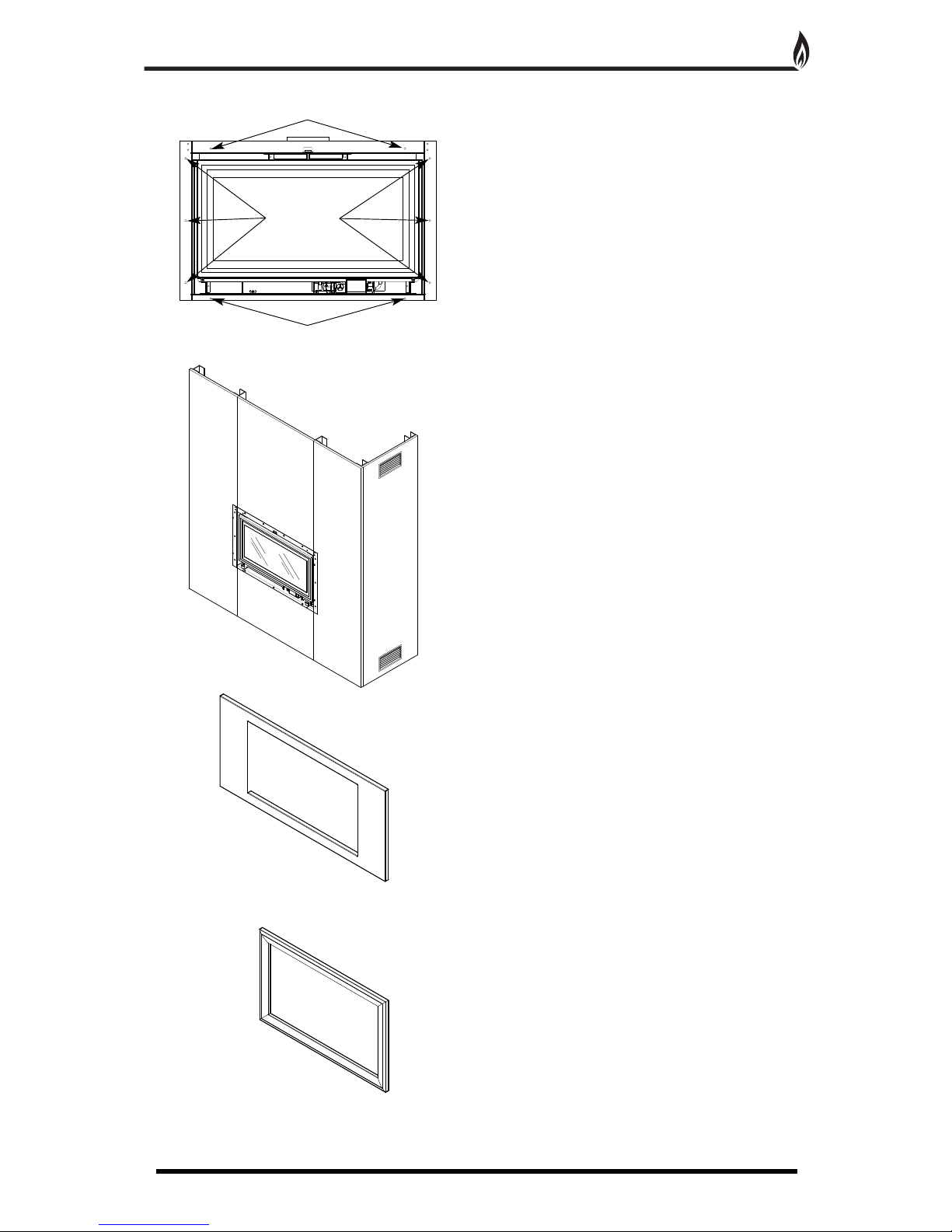
1
1
9
. Locate the drywall fixing kit onto the fire box and
secure with the countersunk screws provided into the
fixing bushes (Fig. 19 & 20).
I
t may be preferential to use the Drywall Fixing Kit to
secure the fire chassis to the chimney breast structure.
This in turn will position the appliance further into the
builders opening and allow for a flush finish to the
f
inished wall surface.
10. Cut and fix drywall boards to the framework of the
chimney breast ensuring they fit neatly around the
flange of the drywall fixing kit (Fig. 21).
11. The chimney breast must have adequate ventilation,
minimum of 200cm
2
. The room will utilise warm air flow
if a vent is fitted at the top and bottom of the chimney
b
reast as shown in Fig (Fig. 21).
12. Locate the drywall trim surround into the opening
and secure to the drywall fixing kit with the four screws
provided (Fig. 21).
13. Sould natural slips be required behind the
appliance, it will be necessary to fit the Drywall Fixing
Kit in front of the wall surface to allow for the 20mm
slips (Fig. 21a & 21b).
D
rywall Fixing Kit
Drywall Board
Vents Minimum (200cm
2
)
Drywall Trim
Surround
Drywall Trim
Surround
F
ixing Bush
Drywall Fixing Kit
fitted on front of wall
surface
20mm slips fitted on
to wall surface
Countersunk
Securing Screw
Fig. 19
Fig. 21
Fig. 21a
Fig. 21b
Fig. 20
Page 12

S
LIPS KIT
1. To install decorative marble or stone slips to the front
of the fireplace opening, the Slips Kit must be used.
2
. The Slips Kit must be bonded to the slips with
suitable heat proof adhesive. The lower slip will sit on
the lower lip of the Slips Kit.
3
. Once the adhesive has cured, locate the surround
into the fire place opening and secure to the drywall
fixing kit with the four screws provided (Fig. 23).
INSTALLATION - Slips Kit
12
S
lips Kit
L
ower Lip
4 Piece Marbe or Stone Slips
Fig. 22
Fig. 23
Fig. 24
Ethos Portrait Slips Dimensions
Ethos Landscape Slips Dimensions
72mm
72mm
20mm
577mm
150mm 150mm
150mm 150mm
72mm
72mm
20mm
421mm
1047mm
1047mm
Page 13

INSTALLATION - Clip-on surrounds
13
For Clip-on surrounds, the fire must be installed so the
f
ire box flange is visible in the room. This will enable the
magnets to secure the surround to the flange.
1. Prepare the builder’s opening following the previous
pages.
2. Insert the end of the flue liner into the flue plate
ensuring that the cable is at the front and secure with
the three self tapping screws provided (Fig. 27).
3. Feed the cable provided through the hole in the flue
plate as shown (Fig. 27).
4. Feed the cable through the hole in the top flange of
the fire box from the rear (Fig. 26).
5. Locate the front of the flue plate into the runners on
top of the fire box (Fig. 27).
6. When the flue plate is located in the runners carefully
pull the cable from the front of the fire and slide the fire
box into the opening at the same time. The flue plate
will slide through the runners and locate the flue over
the opening in the fire box (Fig. 27).
7. With the tab pulled through the slot in the flange of
the fire box, pull tight and bend the tab upwards to
secure (Fig. 28).
8. Cut of the remaining cable flush with the front of the
fire box (Fig. 28).
Cable
Fold Up
Ta b
Cable
Runners
Flue Plate
F
eed cable through
s
mall hole in flue plate
Fig. 27
Fig. 28
Fig. 25
Fig. 26
Page 14
INSTALLATION - Clip-on surrounds
14
F
ixing Holes
F
ixing Holes
Fixing Holes
9. Secure the fire box to the wall using the fixing holes
provided in the fire box flange (Fig. 29).
10. Carefully locate the magnetic surround on to the fire
box flange (Fig. 31 & 32).
Alloy
Surround
Piano Black
Surround
Fig. 29
Fig. 30
Fig. 31
Fig. 32
Page 15

COMMISSIONING
15
7. Remove the burner assembly (two 5mm wing nuts)
and chosen gas inlet plate (Fig. 33 & 34).
10. Relocate the burner assembly and mark/cut gas
pipe to length, then secure burner assembly with the
5mm wingnuts and refit the gas inlet cover plate
(Fig. 33 & 34).
11. Connect manometer to pressure test point on the
brass Pressure Test elbow and ignite the burner to
check working pressure and gas rate see (page 16).
Note: the gas rate is factory set and is not adjustable
without specialised Legend equipment.
12. Refit heat shield, gas connection cover panel must
be always fitted (Fig. 36).
W
ing Nut X 2
Burner Assembly
Burner Top Grill
Rear and Base Gas
I
nlet Cover Plates
Inlet Pressure
Test Point
Gas Connection
Cover Panel
Lower Controls
Heat Shield
Fig. 33
Fig. 35
Fig. 36
Fig. 34
Page 16
COMMISSIONING
16
R
efit all the back-side liner components and slide black
top panel back into position (Fig. 37).
13. At this stage locate the burner top
grille on the tabs provided before slotting
the remaining liner blocks into position.
Note: The pilot tab should be positioned at the front
(Fig. 37a).
14. Follow ceramic layout guide (pages 26-29) fitting
rear log and bark chippings around the black grille and
not on top of the burner skin.
15. Replace the glass door and secure with two 6mm
machine screws screws.
16. Switch on the appliance and carry out smoke
testing as laid out on page 6.
B
lack Internal Top Panel
Fire Box
L
iners
Burner
T
op Grill
Liner
Blocks
Glass
Door
Fig. 37
Fig. 38
Fig. 39
T
ab
F
ig. 37a
Page 17

TECHNICAL DATA
17
1. Log Set - The ceramic logs supplied with this appliance can be replaced at service intervals depending on
their condition. If the logs do require replacement, the consumer can do so provided that the Ceramic
Component Layout Instructions (pages 26-29) are adhered to. Under no circumstances should additional/extra
logs be added. Only genuine Legend replacement parts should be used.
Order Ref: ETHLOG01
2. Oxygen Depletion Sensing Pilot - In the unlikely event of a pilot failure, the pilot assembly should only be
replaced by a
Gas Safe Registered Engineer. The user must not carry out this work. Order Ref: ETH01
3. TESC Valve - In the unlikely event of control valve failure, the assembly should only be replaced by a Gas
Safe Registered Engineer
. The user must not carry out this work. Order Ref: ETH02
4. Glass Panel - Should the glass become cracked or broken, the fire should not be used under any
circumstance.
Order Ref: ETHGLAS01-02
5. Glass Rope Seal - The integrity of the glass rope seal should be checked on service and replaced if
necessary by a
Gas Safe Registered Engineer. Order Ref: ETHSEA01-02
Model Ethos Landscape Ethos Portrait
Gas Type Natural Gas Natural Gas
Gas Category
I
2H
I
2H
Gas Type G20 G20
I
nlet Pressure (mbar) 20 20
Countries of Destination See table below See table below
G
as Valve TESC-01 TESC-01
Injector Size Stereomatic 076 Stereomatic 081
O
xypilot ERTA PG-82 ERTA PG-82
Gas Rate Full Reduced Full Reduced
Nominal Heat Input (Gross, kW) 6.0 2.5 7.4 2.5
Nominal Gas Flow Rate (m3/h) 0.571 0.238 0.705 0.238
Efficiency (net) 87.2 82.3
E
fficiency Class 1 1
NOx Class 3 3
W
eight (Kg) 43.8 48
Countries of Destination
AT, BG, CH, CZ, DK, EE, ES, FI, GB, GR, HR, IE, IT, LT, LV, NO, PT, RO, SE, SI, SK, TR
REPLACEMENT PARTS
TROUBLE SHOOTING (GAS SAFE ENGINEER ONLY)
NOTE: The purpose of the Error code is to give some information as to the potential reason for the fire not
starting rather than just no flame. The appearance of an error code does not mean there is necessary a fault
with the control or the appliance, it could be external factors outside the control that could cause error codes to
appear from time to time and they could just be a one off event , so please check and work through the
suggested service actions below before considering changing the control box. These codes are there to help
with a more certain and efficient servicing of the appliance. Changing the box without working through the guide
could lead to an unnecessary and expensive service and probably a repeat visit to fix the real fault.
SERVICING MUST ONLY BE CARRIED OUT BY COMPETENT PERSONAL WHO HAVE CURRENT
QUALIFICATIONS AND ACCREDITATION (I.E. GAS SAFE)
NOTE: After correcting fault, perform a restart to reset error display to normal standby mode. Also depending
upon the repair
, air will need to be bled out of the system and it may take several start attempts to do so. E00
may appear and need to be reset a few times during the purging process, depending upon the length of supply
pipe. Bleeding the supply pipe via the isolation valve pressure test point will help speed up this process.
NOTE: Before undertaking any actions on the servicing as detailed below , replace the batteries in the control
and handset (if applicable) with new and know to be good batteries. Faulty batteries will cause error codes.
There is a difference between old and faulty batteries and they may give false errors if the batteries are faulty.
ALWAYS CHANGE ALL THE BATTERIES TOGETHER AND NOT JUST ONE OR TWO AND ALWAYS OF THE
SAME MAKE AND TYPE (I.E MANUFACTURER AND MODEL TYPE).
Generally : After replacing the batteries, to clear the error code perform a start cycle by pressing the start button
as normal. Then press again in the same way to attempt a new start cycle. The error code must be cleared this
way after every error code is displayed to start again.
Page 18
TROUBLE SHOOTING (GAS SAFE ENGINEER ONLY)
18
Reset control by pressing start button for 1 second and releasing. Then press again the same way
to attempt a normal start command. Repeat up to 10 times as necessary to see if this overcomes
the issue as it may resolve itself eventually.
Check to see if gas is present at gas appliance inlet. (Check gas supply is on, the gas line purged of
air and the supply pipework is free of blockages or contamination)
Rectify and perform start
cycle to clear the Error code.
Try to light the fire as normal.
No gas on appliance
inlet
Clean the pilot free of any dirt, dust carbon granules or lint, especially around the brass body of the
bunsen burner and its gas and electrical connection and the area around the flame ports and the
spark plug and electrode tip. Check the electrode gap is 3- 4 mm.
Rectify and perform start cycle
to clear the Error code. Try to
light the fire as normal.
Replace pilot if necessary
Pilot contaminated with
lint or other materials
Check ignition cable for damage and listen and watch for tracking out of spark to see if it is present
but not making it to the electrode tip on the pilot burner.
If cable damaged, replace
cable. Reset error by
p
erforming a normal start
cycle and try to start again.
Replace pilot if necessary.
Reset and try again
Reset and try again
No Spark at Electrode
(fire not igniting pilot
b
urner)
Clear pipe and consider changing pilotPilot pipe or pilot injector
c
ould be blocked)
E00
Code Comment Apperance Possible Cause Action
TESC locked due to
failed ignition
Red Led is
permanently on
TESC unit ( and
E
00 on handset, if
used)
Temporary air
disturbance around pilot
burner
C
heck pilot pipe, check flame appearance of pilot flamesE01 Low current from
thermocouple but
f
lame: possibly CO
alarm
F
lashing Red LED
on TESC Control
P
ilot pipe blocked - no
gas reaching pilot
b
urner
Occurs if started ok then subsequently loss of thermocouple current. Check for flue problems. Fire
cuts out to prevent over heating
E02 Too high ambient
temperature ( >73 °C)
a
round control
Negative flue pull or
blocked flue or similar
Reset and try again
C
heck if connected correctly and terminations are sound
E03 No, defective, or bad
c
onnected
thermocouple
B
ad connection
R
eset and try againSensing flame on pilot when no flame should be there. Investigate.E04 False flame signal Occurs during stopping
fire
Reset and try againReplace batteriesE06 Too low voltage on
p
ower supply to start
the burner
Weak or old or defective
b
atteries
R
eset and try again
R
eplace batteries / power adaptor
E
07 Power supply
breakdown during
peak current
consumption
C
heck/change all the
batteries or check power
adaptor. : Note always
change all batteries
together never only 1 or 2
Reset and try againReplace if necessaryE08 Error caused by
external pressure
s
witch
Check the pressure
switch
Reset and try againCheck pressure switch connections, check to see if jumpers are in place on back of TESC.E09 Error caused by
external pressure
switch
Pressures switch action
connection or jumpers
missing or not connected
properly
Reset and try againCheck pressure switch connections, check to see if jumpers are in place on back of TESC.E10
Error caused by
external pressure
switch
Pressure switch action
connection or jumpers
missing or not connected
properly
Reset and try againCheck switch for damage, contamination across terminals or damaged wiring. Disconnect wired
thermostat if fitted and try a start, if it works replace thermostat
E11 Short circuit on wired
thermostat (if used)
Check switch
Reset and try again
Check switch for damage, contamination across terminals or damaged wiring. Disconnect wired
thermostat if fitted and try a start, if it works replace thermostat
E12 Open circuit on wired
thermostat (if used)
Check wiring and
thermostat
Reset and try againCheck switch for damage, contamination across terminals or damaged wiring. Disconnect wired
thermostat if fitted and try a start, if it works replace thermostat
E13 Wired thermostat is
out of tolerance
Check wiring and
thermostat
Reset and try againClean as necessary. Replace switch panel as necessary if damaged or too contaminated.
disconnect wired control panel and try again – if it works replace wired control panel
E14 Button (-) sticks
either on TESC or on
wired control panel (if
used)
Check for contamination
around buttons
Reset and try againClean as necessary. Replace switch panel as necessary if damaged or too contaminated.
disconnect wired control panel and try again – if it works replace wired control panel
E15 Button (+) is shorted
to other buttons
either on TESC or on
wired control panel (if
used)
Check for contamination/
damage
Reset and try againClean as necessary. Replace switch panel as necessary if damaged or too contaminated.
disconnect wired control panel and try again – if it works replace wired control panel
E16 Button (ON/OFF) is
shorted to other
buttons either on
TESC or on wired
control panel (if used)
Check for contamination
/ damage and replace
wired switch panel if
necessary
Reset and try againJumpers on back of
v
alve missing
Check to see if jumpers
a
re in 10 way connector
Reset and try again
Check and clean around the area of the pilot for lint and other contamination. Check where the
thermocouple connects to the TESC control for the same contamination. Clean these areas.
E05
False flame signal Flame sensing on pilot
before start of ignition
sequence or after valve
h
as shut off.
Contamination of
e
lectrode to ground
Reset and try againReplace PilotDefective thermocouple
Check and clearBlocked flue
Reset and try again
C
heck manual for correct placementPoor position of
Ceramic parts
C
heck flueChimney blocked
causing Co / Co2 to
b
uild up in the room
build
Change pilot or thermocouplePilot thermocouple
d
efective / old
Clear error and restart to check ignition okPossible temporary air
d
isturbance on pilot
flame
Page 19

TROUBLE SHOOTING (GAS SAFE ENGINEER ONLY)
19
Reset and try againClean as necessary. Replace switch panel as necessary if damaged or too contaminated.
disconnect wired control panel and try again – if it works replace wired control panel
E17 Button (-) is shorted
to other buttons
e
ither on TESC or on
w
ired control panel (if
used)
Check for contamination
/ damage and replace
w
ired switch panel if
n
ecessary
Reset and try againClean as necessary. Replace switch panel as necessary if damaged or too contaminated.E18 Button (AUX) is
shorted to other
b
uttons on switch
panel
Check for contamination
/ damage and replace
w
ired switch panel if
necessary
R
eset and try again
C
heck if wired correctly and replace IR eye if necessary
E
19
I
nfrared receiver
defective (if used)
C
heck connection of IR
or damage - replace if
necessary IR eye
Reset and try againCheck if wired correctly and replace IR eye if necessaryE20 Illegal setup
p
arameters
Check connection of IR
o
r damage - replace if
necessary IR eye
R
eset and try againUsually only a factory assembly error. Could happen if done in error in servicing.E21 Tried to config a
TESC as Clusterslave
while a wired
thermostat is
connected
F
actory assembly
warning on setup
configuration not a
maintenance error
Reset and try againDisconnect thermostat before attempting using Easy test unit.E22 Tried to calibrate
T
ESC with TESC
easy test while a
wired thermostat is
c
onnected
Not field error
Reset and try againIndicated that control has performed a high number of operations and so fire should be serviced and
c
ontrol replacement should be considered as preventative maintenance. (should not really occur
before 10 years from new).
E23 Warning: end of life is
n
ear, should be
replaced soon
Not field error
R
eset and try againCheck and correct Thermocouple wiring. Replace thermocouple if necessaryE24 Thermocouple
doesn't reach final
c
urrent - damaged or
aged
R
eplace Pilot
R
eset and try againCheck pilot thermocouple connections and connections to TESCE25 Poor thermocouple
signal
Tired or bad connection
of thermocouple or bad
o
r unstable flame on pilot
or poor grounding return
R
eset and try againReplace with new USB power supply of the correct type.E26 Defective or wrong
wired USB-power
s
upply
T
ry again and if
repeatedly fails replace
Reset and try againCheck and correct Thermocouple wiring. Replace thermocouple if necessaryE48 Short circuit on
thermocouple, or
thermocouple
reversed polarity
Wrongly wired
Reset and try againCheck if and clean around the area of the pilot for lint and other contamination and clean. Check
where the thermocouple connect to the TSC control for the same contamination. Clean these areas.
E49
F
alse flame signal
Flame detected during
operation of fire when it
s
hould not be detected contamination of
e
lectrode circuit to
ground
R
eset and try againCheck if and clean around the area of the pilot for lint and other contamination and clean. Check
where the thermocouple connect to the TSC control for the same contamination. Clean these areas.
E
50
Internal error
Reset and try againCheck pressure switch connections , check to see if jumpers are in place on back of TESC.E51 Error caused by
e
xternal pressure
switch
R
eset and try againE52 Error
Reset and try againE27 Error
Reset and try againE28 Error
Reset and try againE29 Error
Reset and try againE30 Error
R
eset and try againE31 Error
Reset and try againE32 Error
Reset and try againE33 Error
Reset and try againE34 Error
Reset and try againE35 Error
Reset and try againE36 Error
Reset and try againE37 Error
Reset and try againE38 Error
Reset and try againE39 Error
Reset and try againE40 Error
Reset and try againE41 Error
Reset and try againE42 Error
Reset and try againE43 Error
Reset and try againE44 Error
Reset and try againE45 Error
Reset and try againE46 Error
Reset and try againE47 Error
Reset and try againE53 Error
Reset and try againE54 Error
Reset and try againE55 Error
Reset and try againE56 Error
Reset and try againE57 Error
Reset and try againE58 Error
Reset and try againE59 Error
Reset and try againE60 Error
Reset and try againE61 Error
Reset and try againE62 Error
Reset and try againE63 Error
F
lame detected during
operation of fire when it
should not be detected contamination of
electrode circuit to
g
round
R
eset and try againCheck and correct Thermocouple wiring. Replace thermocouple if necessaryCheck pilot connections
R
eset and try againClear pipe, replace pilot as necessaryPilot pipe may be
blocked completely
Code Comment Apperance Possible Cause Action
Page 20

Warnings
All parts of the appliance become hot while running and should therefore be considered to be
working surfaces.
A suitable guard may be required to take account of special hazards that exist in nurseries and other
places where there are young children, aged or infirm persons.
Curtains are not to be placed directly above the appliance.
It is recommended that combustible materials are not placed directly above this appliance.
This appliance should not be used if the glass door has been removed, broken or is open.
F
ire Control
This control is situated on your fire. The drawing shows the main features of the control.
Check the power isolator switch is in the On position (I).
To start the fire, press the power button and hold for 1 second then release. The burner will light within around 1
to 10 seconds, adjust to the maximum power setting.
The power of the burner can be adjusted up and down by pressing the – and + buttons.
T
o stop the fire, simply press the power button again and the burner will stop.
If for any reason the fire should be switched off, either intentionally or unintentionally, no attempt should be made
to re-light the gas until at least 3 minutes have elapsed.
If you are not intending to use the fire for a long period (i.e. over summer time months), the battery life can be
extended even more by sliding the white isolator switch to the left (away from the On position to (O)).
USERS INSTRUCTIONS
20
Indicator light
Decrease flame
Increase flame
Battery compartment cover
Battery compartment
cover opening lever
Power button
White power isolator switch (sliding)
Fig. 40
Page 21

Handset
Ensure the Power Isolator Switch on the front corner of Fire Control is in the on position (I).
N
ote: For safety reasons a button must be pressed and released for the command to be recognised. Keeping
h
old of the button when pressing (unless otherwise instructed) will not be recognised as a command press.
Grasp around the handset to unlock its functions. The green unlock light will illuminate to show when the
handset is unlocked and ready to accept commands. (N.B. Keep a grip of handset to keep it unlocked, to
c
ontinue to operate the command buttons.)
USERS INSTRUCTIONS
21
Mode - MAN (Manual), Zzz (Snooze), thermostat or timed.
Time (12 hour or 24 hour display
In range of fire
(
missing if not in range or if
fire controlled turned off)
Room temperature
can be set to
farenheit/celsius
Handset unlocked when
illuminated
To change handset
settings (see handbook)
Press to increase flame
Day of the week
Gas fire burner status
Battery condition
RC handset, FC fire control
Light sensor
(for display backlight)
To change mode
(see handbook)
Press to decrease flame
Power button – To start the fire, (after ensuring the fire control is turned on as described above), with one hand
grasp around the rear of both sides of the button area control. The green unlock light will illuminate. Keep the
handset held to keep the control unlocked, to enable operation of the buttons. Then with the other hand touch
and hold a finger on the power button for about 3 seconds.
A
short beep and a flash of the unlock light will
happen upon touching. When the word “pilot” appears at the bottom left hand corner of the display, immediately
release the power button. The Fire should be lit within a few seconds.
(N.B. If power button is held for more than a few seconds after second flash/beep/word pilot appears, the
command is ignored for safety reasons. Similarly if it is released too soon before the word “pilot” appears, the
command would also be ignored.
Fig. 41
Page 22

Operating instruction (Detailed)
T
HE HANDSET AND CONTROLS SHOULD ALREADY BE PAIRED AND THE DAY AND TIME SET
C
ORRECTLY.
SHOULD ANY ADJUSTMENTS BE NECESSARY SEE INSTRUCTIONS BELOW:
S
etting the time
Following pressing “SET” at paring above, the display will be as shown, as the time is not set yet
and will progress automatically to the next screen shown below.
Note: the legend at the bottom shows the battery condition of both the batteries in the hand set
a
nd in the fire control alternately. RC = Remote Control handset and FC = Fire control. The
control is designed to get the most out of the batteries but when eventually the display shows
they are spent(when the battery legend is a empty area, we recommend you change the batteries
in the handset before they are flat, to avoid having to re-program the time of day in again.
N
.B. Pairing is not lost, even if the batteries are removed or flat.
Setting the display for 12 or 24 Hour display
As always when pressing the remote control buttons keep the control held to keep the green light
on and therefore handset safety feature, unlocked. The H indicates that it is time to set the timer
to either 24 hour display or 12 Hour (AM or PM ) display. Press the + or – button on the handset
to toggle between the two settings. When you are ready to confirm the setting you want press the
“SET” button to progress to setting the day of the week.
Setting the day of the week
Press and release the + and – buttons until the correct day of the week is shown on the display.
(Mo = Monday, Tu= Tuesday, We=Wednesday, Th=Thursday, Fr=Friday, Sa= Saturday and
Su=Sunday).
Press “SET” to accept the day of the week and to progress to setting the Hour of the day.
Note: Whilst doing this setup pressing “SET” advances to the next display and pressing “MODE”
will return you to the previous display setting.
Setting the Hour
Press and release the + or – button to change the hour to the correct hour and press set to store
and to move to setting the minute. Repeat this for setting the minutes.
Setting the temperature display to Celsius or Fahrenheit.
Press and release the + or - button to toggle between C and F
. When the display shows the
desired symbol, press and release the “SET” button to store.
As the important settings above have now been done. Press and hold (not releasing straight
away) the “SET” button for a few seconds and this will exit the setup menu.
The control is now ready for use with the Fire Control.
USERS INSTRUCTIONS
22
Fig. 42
Fig. 43
Fig. 44
Fig. 45
Fig. 46
Page 23

Paging the handset
I
f you have misplaced the handset you can page it by pressing the + button only on the fire control for around 5
s
econds. The handset will flash and make a noise to help you to locate it. Once you pick up the TESC it knows
you hold it and so the sound stops. The flashing and sound will last for 60 seconds each time the handset is
paged as described. If not found in 60 seconds,
page again and so on.
NOTE: Press “+” button ONLY, NOT “+” and “-” together. This will break the handset pairing and have to
reset handset to factory state and pair again.
Advanced settings Menu
In the event that you may want to change the other preset settings of the control features. Do not do a long
press and hold above but a normal short press and release will take you into the advanced settings area.
A
dvanced settings options are:-
•
Back light –
• A = Automatic (default setting). The back light comes on in the dark but not in the light.
• 0 = Light never comes on.
• 1 = Light comes on when ever handset is unlocked.
• Display contrast – 8 levels from 0 to 7 (default level 4) .
• P = pairing with other devices other than the fire control. The hand set can pair with other modules to:-
• L= Operate an electric light – which is the dimmable in 9 steps
• F= operate an electric fan –which can have 9 speed levels
• A= operate an auxiliary contact to operate another device.
Other Modes than Manual Mode
Depending upon the model of Fire your handset maybe enabled to have some automatic features, namely,
Thermostat mode, timed thermostat mode and snooze mode. Snooze mode can be selected to work with in
conjunction with either manual or thermostatic modes. You can switch between modes at any time with the
handset unlocked by pressing and releasing mode button to toggle between modes.
Note: If at any time the power button is pressed during operation, this will stop the fire and exit any automatic
mode and return the handset to manual (MAN) operation mode.
Factory Reset of Display Handset (to enable handset to be paired again)
To reset a handset to factory conditions to enable it to be paired with a new control. Hold the handset to unlock.
Press and hold set until handset beeps and release the set button. PROG will be at the top left corner
. Press
and release the mode button until the word SETUP is flashing in the top right corner.
Press and release SET to enter the SETUP menu.
Press and release the set button around 9 times until you see CA0 on the display
.
Press then release the + (or – button) to change the display to CA1 and press and release the SET button again.
The word
TESC will appear in the window to show that this handset is now reset and ready to pair again.
Snooze mode in manual operation
Snooze mode is a time period you can set which will turn of
f the fire after a certain time period has elapsed.
The snooze time period can be set before or during manual operation of the fire. Hold the handset to unlock as
described previously and press the mode button as many times as necessary until the word MAN and the Zzz
symbols are flashing at the top of the display. Press and release the set button and this will put the control into
Manual snooze mode.
The default time period for the snooze time period is 1:00 hour. Pressing the set button again will show you the
snooze time period remaining. This can be adjusted by pressing the “+” or “-“ buttons. The timer period that can
be set is from 1 minute to 4:00 hours.
After adjusting the time, press set again to enter the time setting required (or if left for a few seconds this time is
now stored and used).
Once this countdown timer has reached zero the fire will turn of
f (as if you had pressed of
f manually, it does not
recycle).
USERS INSTRUCTIONS
23
Page 24

Snooze mode in Thermostatic mode
T
he same thing as above can be done before or during a thermostatic mode operation (see below).
Thermostatic mode only
The handset has within it a thermostat sensor and this can be set so the fire will heat the room to match the
t
emperature set in the handset.
There are 3 temperature types that can be set:-
-Day mode temperature that has a sun symbol on the display – the default
temperature is 24 °C
-
Night temperature that has a half moon symbol on the display- the default
temperature setting is 18 °C
-frost protection that has a snowflake symbol on the display – the default
temperature setting is 5 °C
H
old handset and press and release the mode button several times as necessary until the display has a
thermometer symbol flashing at the top of the display. Press the set button to enter this mode.
Press the set button again to see the temperature setting that is set and the mode (the default is 24 C ) and on
the left of the display is a sun symbol showing it’s the day temperature.
If a different set temperature is required, while the display is showing this set temperature , press the + and –
buttons to alter the setting. When finished either press set or leave and after a few seconds the new setting
will be accepted and the display will return to the time of day screen.
On the anniversary of the net minute of the clock, the set temperature will be compared to the actual
temperature displayed on the handset(i.e. the room ambient temperature around the handset).
Note: If at any time the power button is operated during Thermostat mode, the control will cancel any thermostat
operation and return the control to manual mode.
For ease of setting there are two other modes that can be selected as stated above. Night mode (moon symbol)
and frost protection setting (a snow flake). These can be selected (and adjusted if necessary) by pressing set
then mode while in thermostat mode. Pressing mode button toggles through from day to frost modes.
Note: As stated in an earlier section, snooze function can also be operated in conjunction with thermostat mode.
The thermostat symbol and the Zzz symbol will be on together when in this mode.
Pairing the Handset to the Fire Control
Should the handset fail to operate the fire control, it may need to be re-paired with the system.
The handset must be within 1 metre (3 feet) of the fire when pairing.
After fitting the batteries as above (and with the power isolator slide switch on the TESC Fire control put in the
on position), simultaneously press and hold the – and + buttons on the fire control (i.e. not the handset) until the
handset makes a noise and the display shows the pattern as shown here.
Hold the handset in one hand so your fingers wrap around the back of the operating buttons area of the handset.
A green unlock light will illuminate when the handset has detected your hand. The green light must be
illuminated in this way for any of the command buttons to accept commands
to operate the fire control.
While the display is as shown, and holding the handset as described, press the “SET” button with
the other hand to finish off the pairing of the handset to the Fire Control and to enter the setup the
time of day on the handset.
N.B. If the display returns to the one shown above with the word “TESC” shown, then too much
time has passed before pressing “SET” and so the handset has not paired yet. Simply repeat
pairing again.
N.B. Only ever press “+” and “-” buttons together when pairing handsets. If done afterwards this
will break the pairing made and a factory reset of the handset will need to be performed, see
Factory Reset of Display Handset later on in the instructions.
USERS INSTRUCTIONS
24
Fig. 47
Page 25

CLEANING AND MAINTENANCE
25
Stainless Steel Burner
Pilot Assembly
2
x Securing Screws
30°
10mm
Fig. 51
Fig. 50
Fig. 49
Fig. 48
I
t is recommended that this appliance is serviced at regular
12 monthly intervals. The chimney or flue should also be
checked regularly to ensure that all products of combustion
are entering the flue and there is no excessive build up of
s
oot.
It is the users responsibility to ensure that the appliance is
kept in a clean serviceable condition.
T
o remove the glass door
1. Remove the two screws at the bottom of the glass door panel
(Fig. 48).
2
. Hinge the door upwards by approximately 30° (Fig. 48).
3. Slide the door to the right by 10mm and remove the door from
it’s hinges (Fig. 49 & 50).
4
. Clean the glass with a damp cloth. For stubborn stains use
a proprietary cream cleaner or ceramic hob cleaner.
Ceramic Components and Fuel Bed
Debris from any source should be removed with a soft brush.
Please ensure that any debris including soot deposits are
removed from the appliance and not left on the fuel bed.
It is recommended that the user should, on a regular quarterly
basis, carefully remove all ceramic components and thoroughly
clean the stainless steel burner and the pilot assembly.
Any build up of debris in this area could affect the
operation of the appliance (Fig. 51).
NOTE: It is common to find surface cracks in the ceramic
components. This is due to the expansion and contraction of
the ceramic fibres caused by the intense heat that the burner
generates. The cracks will not affect the safe operation of this
appliance. However great care must be taken when handling
the ceramic components as they will break if handled
incorrectly. Do not use a vacuum cleaner to clean the ceramics.
Radiant Box Ceramic Liners - Use only a soft brush to remove
any soot deposits from the ceramic liners
during cleaning as this is the only method that can be used to
remove deposits. The ceramic liners are very
delicate and should be treated accordingly.
5. Reassemble in reverse order.
Page 26

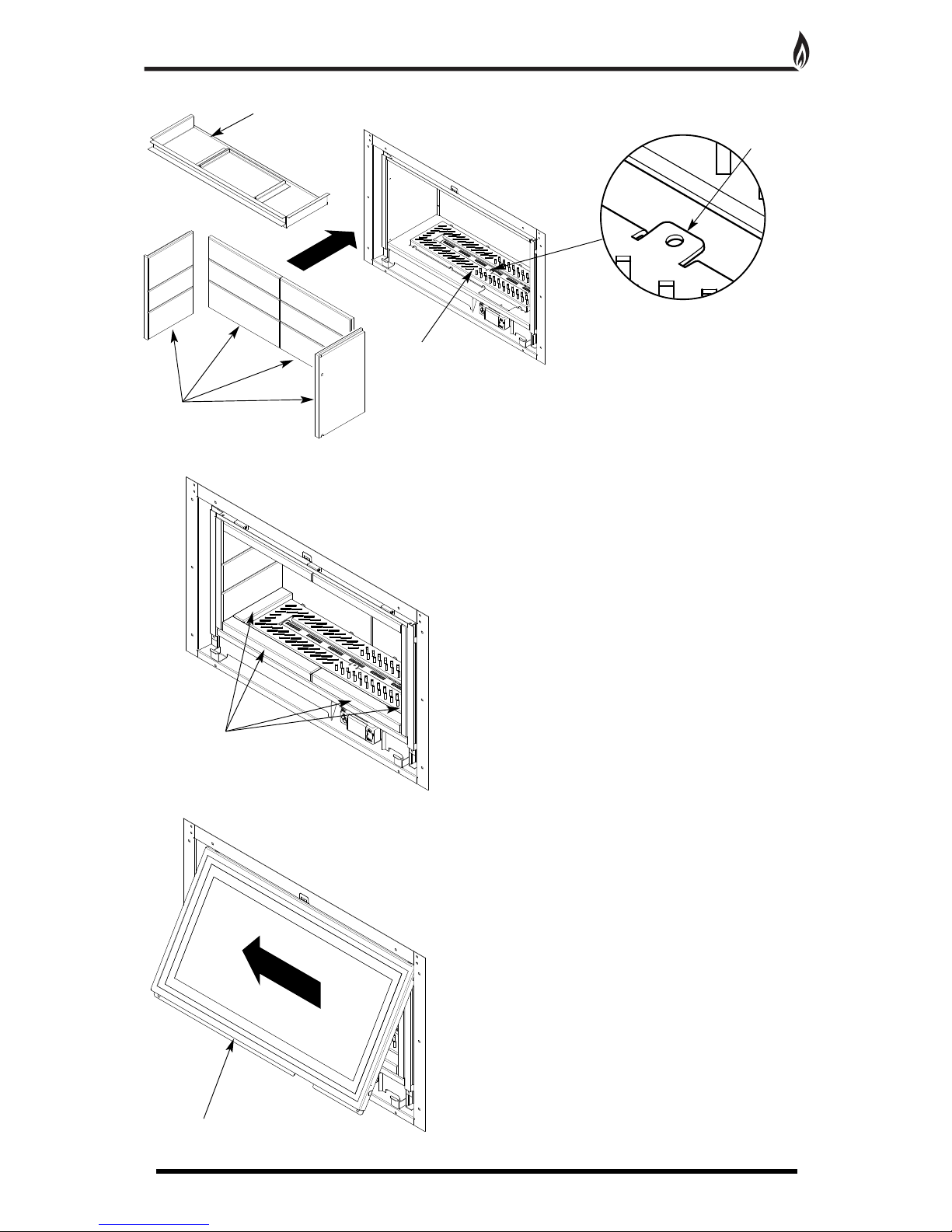
LOG LAYOUT INSTRUCTIONS
25
1. Place the rear ceramic panels into position.
2. Place the side ceramic panels into position.
Note alignment of grooves.
CAUTION: The logs are extremely fragile and must be handled accordingly. Gloves should be worn
and any inhalation of dust should be avoided. The logs must be kept away from children at all times.
Never put additional logs on the fire. Never use logs other than those originally supplied, or genuine
L
egend Spare Parts.
4. Insert the burner grille into position, ensuring the
pilot tab is towards the front of the fire.
6. Place the large log at the rear of the burner cover
plate. ENSURE THAT IT DOES NOT COVER THE
BURNER.
7.
Arrange the slate ceramics onto the burner cover plate.
ENSURE THAT THEY DO NOT COVER THE BURNER.
3. Carefully slide the top tray into the firebox along the
top edges of the side ceramic panels.
5. Place the six ceramic bricks into position, four on the
bottom and two in the top tray.
26
Page 27

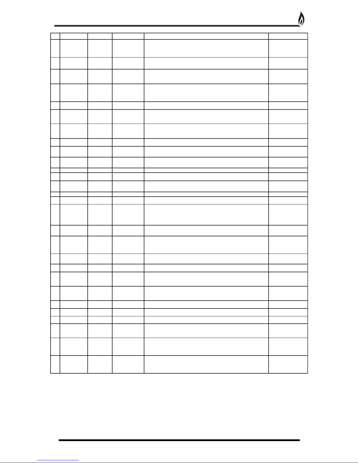
LOG LAYOUT INSTRUCTIONS CONTINUED
27
9. Place the remaining logs as shown in the photographs below.
8
.
9.
10.
11.
12.
13.
14.
It is very important that all the logs are used and arranged as shown in order to achieve the desired flame
picture. It may be necessary to remove some or all of the logs to clean them at some time.
Cleaning must only be done using a soft brush.
Page 28

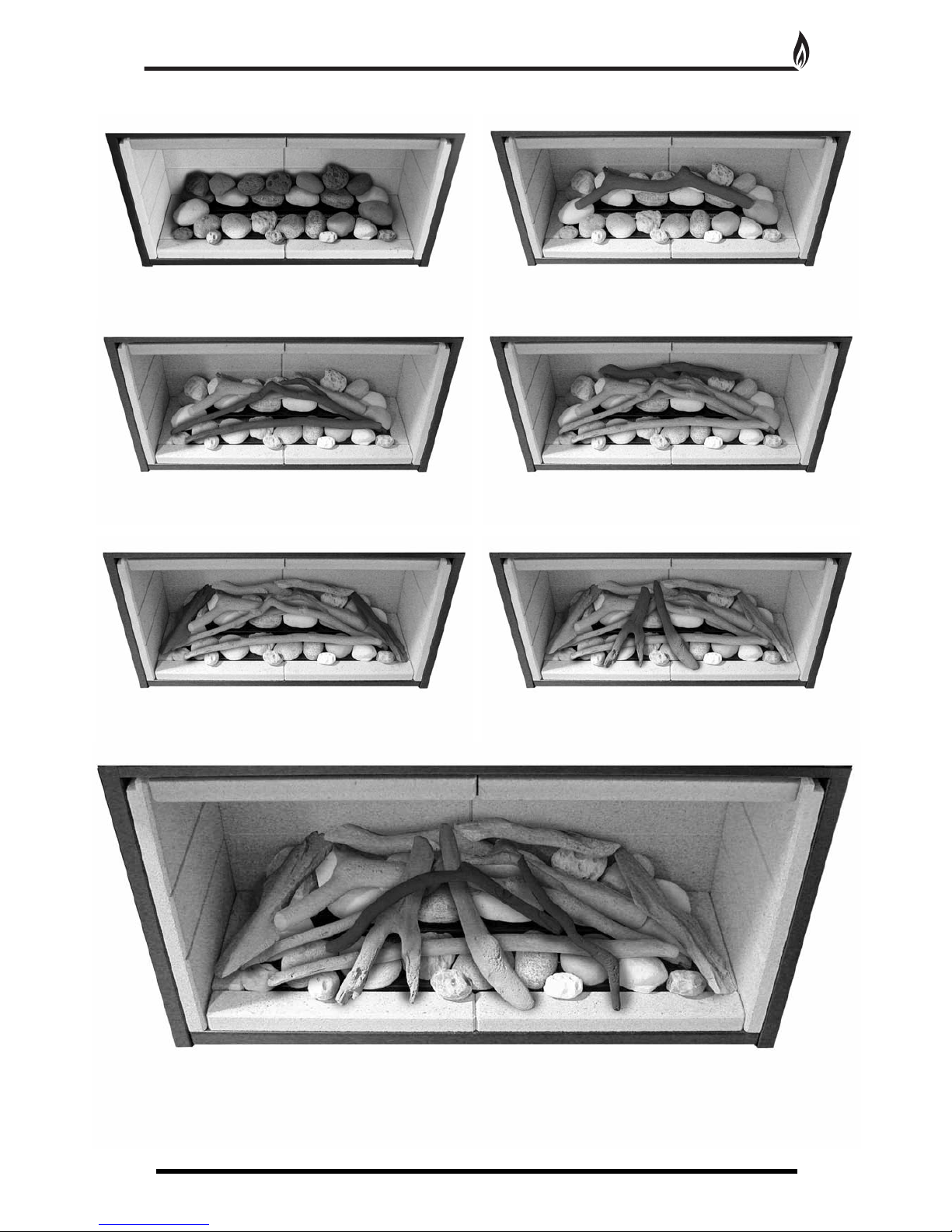
PEBBLE & DRIFTWOOD LAYOUT INSTRUCTIONS
28
1. Place the rear ceramic panels into position.
2. Place the side ceramic panels into position.
Note alignment of grooves.
CAUTION: The pebbles & driftwood are extremely fragile and must be handled accordingly. Gloves
should be worn and any inhalation of dust should be avoided. The pebbles & driftwood must be kept
a
way from children at all times. Never put additional pebbles & driftwood on the fire. Never use
pebbles & driftwood other than those originally supplied, or genuine Legend Spare Parts.
4. Insert the burner grille into position, ensuring the
pilot tab is towards the front of the fire.
6. Place fifteen of the larger pebbles around the burner
cover plate. ENSURE THAT THEY DO NOT COVER
THE BURNER.
7. Place five of the smaller pebbles at the front of the larger pebbles.
3. Carefully slide the top tray into the firebox along the
top edges of the side ceramic panels.
5. Place the six ceramic bricks into position, four on the
bottom and two in the top tray.
28
Page 29
PEBBLE & DRIFTWOOD LAYOUT INSTRUCTIONS CONTINUED
29
9. Place the remaining pebbles and driftwood as shown in the photographs below.
8.
9
.
10.
11.
12.
13.
14.
It is very important that all the pebbles and driftwood are used and arranged as shown in order to achieve the
desired flame picture. It may be necessary to remove some or all of them to clean at some time.
Cleaning must only be done using a soft brush.
Page 30

Non Display handset with pilot burner
If the fire does not start at the first attempt it may retry several times to do so. At the end of trying if it cannot
i
gnite the burner; it will show a RED light on the handset and on the fire control and stop the fire.
• If the fire does not light first time, allow fire to cool and then repeat lighting fire up to 10 times, as it may only be
a temporary reason that will clear after a few attempts..
• Reset the fire control by pressing the handset as if you were doing a normal start. This will clear the red light
and allow another subsequent restart attempt.
• If the fire does not light, replace all the batteries in the handset and the fire control, (5 x AA Alkaline in total,
w
ith batteries that do not leak) with new and known to be good batteries and repeat the above starting of the fire.
• While replacing the batteries, check that the battery contacts are not contaminated with anything that may have
leaked out of the batteries that may have damaged the contacts.
• If the fire still fails to light check to see if the pilot flame on the pilot burner, is lighting during the starting
sequence. If not then clean the pilot as described in Cleaning the pilot section of the booklet.
• Check to see if there is a spark appearing on the pilot spark plug and check to see if there is any contamination
around it that might be preventing the ignition spark from happening.
Display handset with pilot burner
As above except instead of the red LED light on the handset there will be a letter E and a to digit number where
the time is usually displayed. Do the same actions as above to try and resolve the reason for non ignition of the
burner.
If you cannot resolve the problem, then call:
01254 695244.
Your appliance is guaranteed for one year from proof of purchase. Should the appliance prove defective within
that period we agree to repair or replace (at our discretion) the component or appliance provided that:
1. The user can produce a receipt for proof of purchase/installation.
2. The appliance has been supplied by an authorised stockist and has been installed by a qualified installer, all
installation and operating instructions have been strictly adhered to.
3. No alterations have been carried out on the appliance or component parts without our written consent.
4. The appliance has not been used for any purpose other than those intended.
5. The appliance has not been damaged accidentally or due to fair wear and tear.
Guarantee claims should be made through your appliance supplier. The Guarantee is restricted to UK Mainland
and is additional to your statutory rights.
TROUBLE SHOOTING (USER)
30
GUARANTEE
Page 31

Page 32

Unit 404 Glenfield Park Business Centre Blakewater Road Blackburn Lancashire BB1 5QH
T
el: 01254 695244 Fax: 01254 695255 W
eb: www
.legend-fires.com Email: info@legend-fires.com
Issue 2 - 10/3/14
 Loading...