

Page 1

Owners Manual For The
AERIS
Loudspeaker System
Page 2

1
THANK YOU FOR
CHOOSING
LEGACY AUDIO
Aeris is a full range loudspeaker system utilizing the present state of
the art in driver, crossover, amplifier and acoustic radiation control
technologies.
The system is designed, assembled and tested in Springfield, Illinois
by a dedicated group of engineers, craftsmen, and music lovers.
Please take a few moments to learn more about the features and controls of these instruments to assure full enjoyment.
Page 3

2
Table of Contents
Registration
Page
Owners Record 3
The Cabinetry / Our Commitment 4
Warranty 5
Setup
Speaker Installation 6
Hooking Up Cables 7-8
Amplification 9-11
Speaker Connections 12-15
Wavelaunch Processor 16-24
Technology
Continuing the Pursuit of Perfection 25-26
Specifications
27
Wavelet for Aeris 28
Page 4

3
Owners Record
The serial number is located on the rear of the unit. Record this
number in the space provided below. Refer to this when calling your
dealer regarding this product.
Model: AERIS
Serial No: _________________________
Date of purchase: ___________________
Thank you for selecting a Legacy Loudspeaker System. These handcrafted instruments will provide you with many years of listening enjoyment.
Page 5

4
The Cabinetry / Our Commitment
Handcrafted
Beneath the surface of AERIS’s elegant exterior lies rigid MDF
construction. Interlocking joinery maximizes the strength of the cabinet
parts. Polyester fiberfill is selected for internal damping. A sharp rap on
the enclosure will leave you with little more than bruised knuckles.
Each cabinet is impeccably finished on all exposed surfaces with select
veneers. The exquisite finish is hand-rubbed several times to assure a
patina at home with the most elegant decor.
Our Commitment
A great deal of forethought, love and satisfaction is instilled in each piece
of Legacy workmanship. We take pride in getting to know many of our
customers on a first name basis.
Your purchase of this product is backed by the renowned “Legacy
Satisfaction Guarantee”.
Page 6

5
Warranty
Legacy Audio supports its customers and products with pride. We cheerfully warrant our loudspeaker products we manufacture from defects in materials and workmanship for a period of seven
(7) years. Electronic components such as internal amplifiers and digital processors are covered for
three (3)years. Please register your product with Legacy Audio. Should you require service Legacy
will require a proof of purchase in order to honor the warranty - so please keep your receipt.
• The warranty applies to the original owner and is not transferable.
• The warranty applies to products purchased from an “Authorized Legacy Dealer”.
• The warranty on active components such as digital processors or internal amplifiers is limited to three
(3) years of coverage.
• The warranty on dealer stock will extend for a maximum of two years from invoice.
The warranty does not cover transportation costs of product to or from the customer, distributor or
dealer, or related shipping damage.
Exclusions from Warranty
The following situations or conditions are not covered by the Legacy Audio warranty:
• Accidental damage, electrical abuse or associated equipment failure.
• Use inconsistent with recommended operating instructions and specifications
• Damage caused by modification or unauthorized service
• Costs associated with the removal and reinstallation of defective products. Consequential damage to
other products.
• Normal wear such as fading of finishes due to sunlight.
Page 7

6
Speaker Placement
To allow more flexibility in seating arrangements, your Legacy loudspeaker is
designed for broad lateral coverage. Optimal listener position is actually
about 5 to 15 degrees off the axis normal to the loudspeaker baffle. Assuming a listener distance of about 10-12 feet, begin by placing the speakers approximately 8-10 feet apart and about 1 – 3 feet from the wall behind them.
In most rooms this will afford a speaker position at least 2 feet or more from
the side walls. The amount of recommended "toe-in" is a function of the listening angle. As the overall listening angle increases from 40 degrees, the
amount of toe-in should increase. Your Legacy speaker is optimized for a flat
response in the far field. Best results are obtained vertically with the listener's ear at tweeter level with the loudspeakers gently toed in toward the
listener. Increasing the degree of toe-in is recommended when placement
next to sidewalls is required. Placing the loudspeaker or the listener near a
room boundary will generally increase low frequency impact. If you are
forced to position one or both of your loudspeakers in a corner, be prepared
to reduce bass output via the XP-4080 or with your preamp's bass tone
control.
Page 8
7
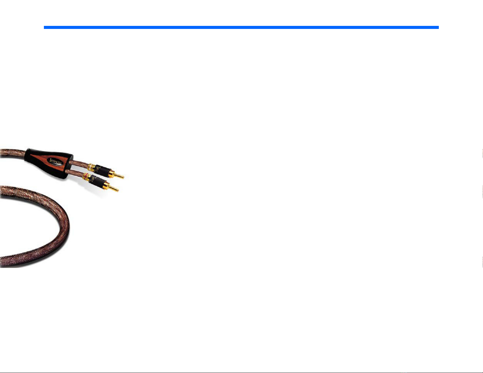
Hooking Up Cables
The ideal conductor would have negligible resistance, inductance
and capacitance. The table below shows how a few actual speaker
cables measure up.
Cable Ωs/ft pF/ft µH/ft
12 ga. 0.0033 24 0.21
14 ga. 0.0048 17 0.13
16 ga. 0.0079 16 0.18
18 ga. 0.0128 28 0.21
Capacitance is considered insignificant in each cable because its effect is well out of the audio bandwidth; inductance can be decreased (at the expense of increased capacitance) by keeping the
conductor pair closely spaced.
How long would a cable have to be before inductance effects would
impinge on the audio spectrum? Approximately 300 feet of 12 gauge
would be required to establish a corner frequency of 20 kHz with an
8 Ohm loudspeaker. As you see, inductance is not a problem for
most of us.
Page 9

8
Hooking Up Cables
What about phase shift due to frequency dependent travel times down the speaker
cable? Measurements show that 100 Hz waves will be delayed about 20 billionths of a
second behind 10 kHz waves when traveling to the end of a 10 foot speaker cable.
Since the cilia of the ear requires 25,000 times longer than this just to transmit phase
information, phase shifting is obviously not the primary concern when considering
speaker cables.
What about resistance? Finally we are getting somewhere. Resistance is the controlling factor of the amplifier/loudspeaker interface. Excessive resistance can cause major shifts of speaker crossover frequencies. The lower the impedance of the loudspeaker, the greater the effects of series resistance. A 20 foot run of 18 gauge cable
can cause up to 10% deviations of crossover center frequencies. That same 20 feet
can un-damp your damping factor and reduce your systems’ output by onehalf decibel.
In summary, there are no perfect cables. The best way to approximate the ideal
would be to keep loudspeaker leads as short as is practical.
Page 10
9
Amplification
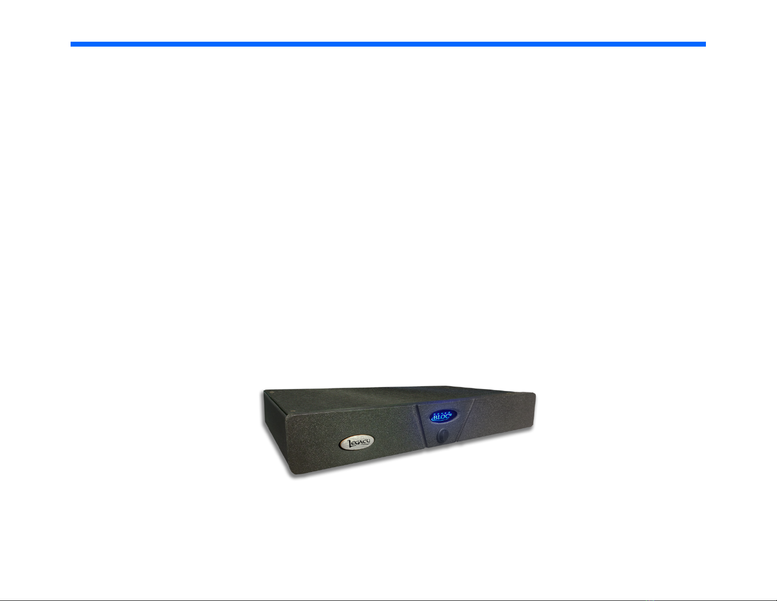
Ideally the loudspeaker would be among the first components selected when assembling a playback system. This would allow the user to choose an amplifier capable of delivering adequate
amounts of current into the frequency dependent load presented by the loudspeaker. However,
when upgrading a system, audiophiles may find themselves matching their new loudspeakers to
their existing amplification. For this reason, extensive measures have been taken to ensure that
each Legacy speaker system represents a smooth, non-reactive load to virtually any amplifier.
Often there is much confusion regarding amplification and loudness levels. It should be understood that the role of the amplifier goes beyond that of driving loudspeakers to a given sound
pressure level. The amplifier should be able to CONTROL the loudspeakers across the entire music spectrum. This means that parameters such as damping factor (values greater than 60 are
acceptable) and dynamic headroom should not be overlooked when comparing amplifiers.
Page 11

10
Amplification
How much power will your new speakers need? That ultimately depends on
your listening environment and musical tastes. As little as five watts per
channel should drive them to a level satisfactory for background music. A
typical 45 watt per channel receiver may fill a room with the compressed
mid-band energy of “heavy metal,” but seem to lack weight or control with
classical recordings. Some audiophiles feel that 200 watts per channel is the
bare minimum to avoid audible clipping distortion when reproducing music
at “live” playback levels. Your Legacy speakers are designed to take advantage of “high-powered” amplifiers, so don’t be afraid to put them through
their paces.
How much is too much power? Rarely is a drive unit damaged by large
doses of music power. More often than not the villain is amplifier clipping
distortion. Even through decades of refinement, loudspeakers are still notoriously inefficient transducers, requiring huge amounts of power to recreate
the impact of the live performance. Typically less that 1% of electrical
power is converted into acoustic output. (For example, an omnidirectional
transducer with an anechoic sensitivity of 90 dB @ 1w/1m has a full space
efficiency of only 0.63%)
Page 12
11
Amplification
When an amplifier is unable to fulfill your loudspeakers demands, a
damaging harmonic spike may be leaked to the high frequency drivers.
Another important point regarding loudness is that the dB scale is a
logarithmic one. This means that a 150 Watt amplifier will potentially sound
only twice as loud as a 15 Watt amplifier. If all of this discussion of power
and loudness seems a bit abstract, consider the example below.
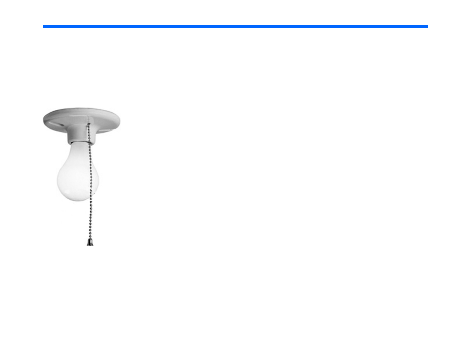
The average acoustical power developed by a person speaking in a
conversational tone corresponds to a mere 0.00001 Watts. The power that
would be developed by the entire population of the city of New York
speaking at once would barely illuminate a single 100 Watt light bulb.
Page 13

12
Speaker Connections
Connecting the Speakers
Connect the L, R speaker cables from each upper range amplifier channel
to the respective speaker’s +, - binding posts. You may use spades, bare
wire or locking banana pins. Be sure that no stray wires bridge between
the input posts to prevent electrical shorting and take care that correct polarity (+, -) is observed .
When wiring connections are completed as above, complete the AC connection to the external socket of the internal amplifiers of each Aeris speaker
by connecting the provided cord to the room wall plate, power strip or
power filtration unit. Power up the processor next via the rear panel
switch, and finally rock the I/O switch on the rear panel of the Aeris to the
“I” position to turn on the internal amplifiers. Note that these amplifiers are
green compliant, idling at a few watts. They will automatically turn themselves on when a music signal is present, providing up to total of 1000
watts of power to the woofers.
Crossover Illumination
Aeris benefits from premium Clarity capacitors, Kimber HF Silver wire and
custom wound copper coils. We have made it possible to view the internal
crossover and the dipolar midrange/midbass alignment by rocking the
Crossover Illumination switch to the ON position. A series of low-voltage,
long-life LEDs will allow viewing. To defeat the illumination feature, simple
rock the switch into the down position.
Page 14

13
Speaker Connections
XP-4080 Processor Cable Connections
For use with standalone amplifiers
From To
Left channel of preamp output Processor Input 1 and Input 3*
Right channel of preamp output Processor Input 2 and Input 4*
(use Y adapter)
(use Y adapter)
Processor Output 1 Left Aeris rear panel Bass Input (XLR)
Processor Output 2 Left channel input to amplifier driving Aeris upper range
Processor Output 5 Right Aeris rear panel Bass Input (XLR)
Processor Output 6 Right channel input to amplifier driving Aeris upper range
*The redundant feed of left and right input signals to the processor allows a low frequency correction algorithm to be applied. This compensates for the decrease in channel separation at longer wavelengths in listening rooms. This algorithm
may be defeated at any time by muting inputs 3,4 on the processor’s front panel.
Page 15

14
Speaker Connections
XP-4080 Processor Cable Connections
For use with integrated amplifiers
From To
Left channel pre-out of integrated Processor Input 1 and Input 3*
Right channel pre-out of inegrated Processor Input 2 and Input 4*
(use Y adapter)
(use Y adapter)
Processor Output 1 Left Aeris rear panel Bass Input (XLR)
Processor Output 2 Left channel amp in on integrated amp driving Aeris upper range
Processor Output 5 Right Aeris rear panel Bass Input (XLR)
Processor Output 6 Right channel amp in on integrated amp driving Aeris upper range
*The redundant feed of left and right input signals to the processor allows a low frequency correction algorithm to be applied. This compensates for the decrease in channel separation at longer wavelengths in listening rooms. This algorithm
may be defeated at any time by muting inputs 3,4 on the processor’s front panel.
Page 16

15
Two 1m Y-cables with RCA Male to XLR Male
Two 1m XLR cables with XLR female to RCA Male
Two extended length balanced XLR cables to bass section
Speaker Connections
Page 17
16
Wave Launch Processor
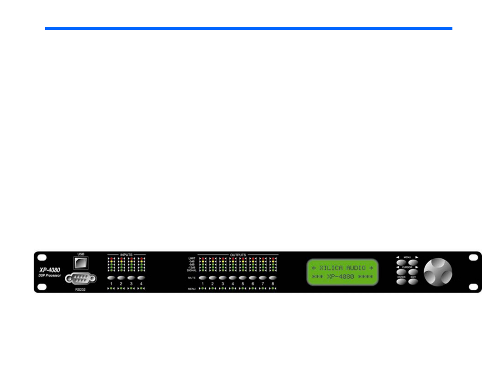
The high definition Digital Wavelaunch Processor hosts a LEGACY custom algorithm which automatically loads when the processor is powered on. Factory settings are ‘plug and play’, and do not require a computer to utilize. Connections between the
preamp, power amplifier, and speakers should be as shown on previous page.
Selecting the Program
1. Press the enter button
2. Scroll through the programs using the job wheel
3. Press enter to select the program of choice
4. Press enter again to confirm selection. The program will now load.
Users are welcome to load the included software and learn to make individual adjustments as desired. However it is recommended that any changes be saved as Program 6 or higher to avoid overwriting the factory settings.
Page 18

17
Wave Launch Processor
Downloading and Installing the XConsole software
Downloading
From Included CD
Your Wave Launch Processor will come with a CD or USB drive containing the XConsole
software. Insert the CD and find the install file. Move/Save the install file to your
computer.
From Xilica Website
- Go to www.xilica.com
- Click on the “Downloads” tab at the top of the screen
- Click “XConsole” on the Left and then Click “Software”
- Click “XConsole software” to start the download
- Save and Extract the installation file on your computer
Installing
- Double click on the install file and follow the on– screen instructions to install the software.
Page 19
18
Wave Launch Processor
The XP processor will allow you to make adjustments to your system from a laptop computer
from your listener position.
Connecting Your Computer with the XP-4080 Processor
- Connecting will require a long USB Device cable. These can be found at most electronic or big box stores. It is the
same cable that a USB printer would use. This 16 ft cable is available at Radio Shack.
http://www.radioshack.com/product/index.jsp?productId=3584358&filterName=Length&filterValue=16-20+ft.
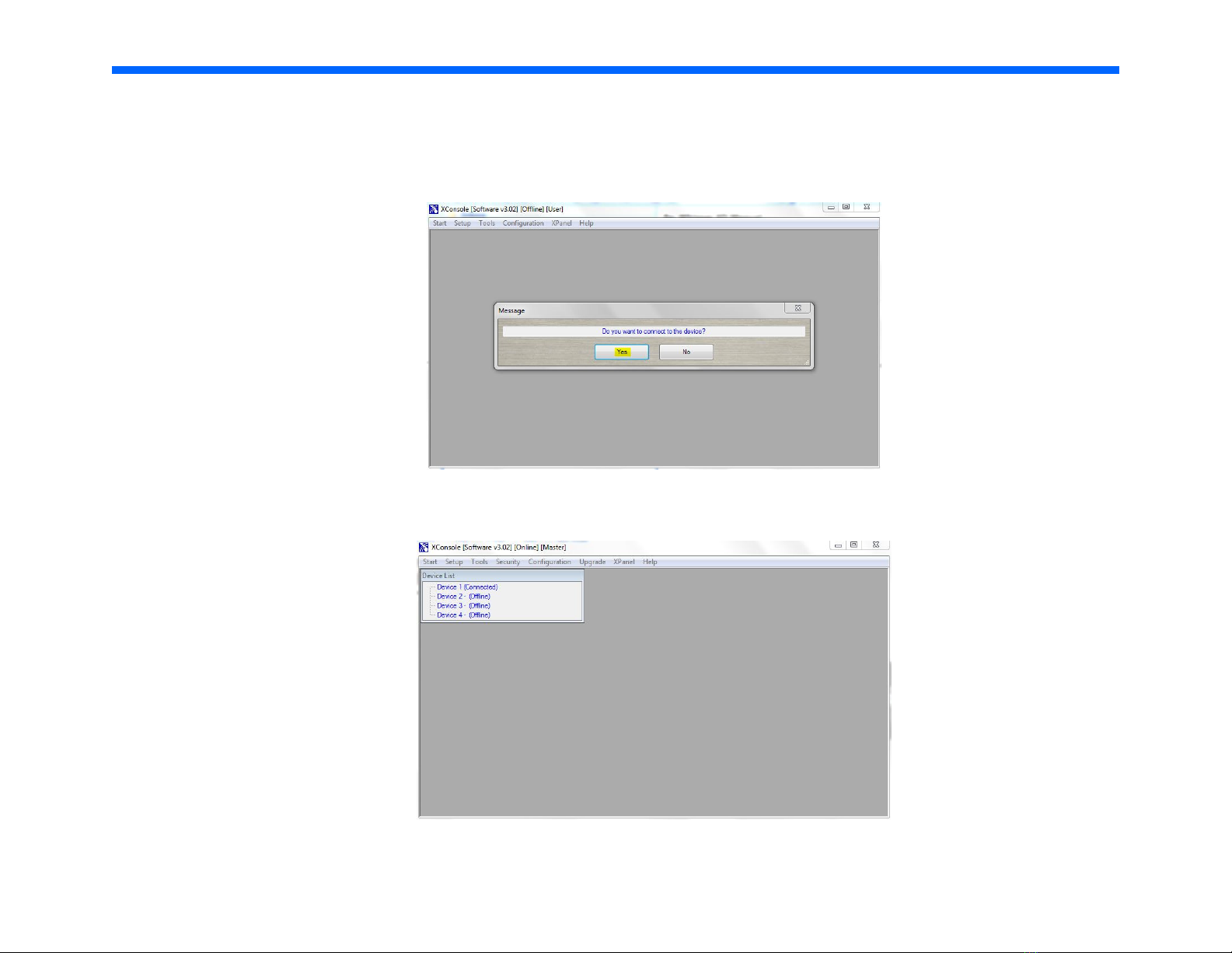
- Once the cable is connected, start the XConsole software. It will ask “Do you want to connect to the device?”, answer
“No” for now.
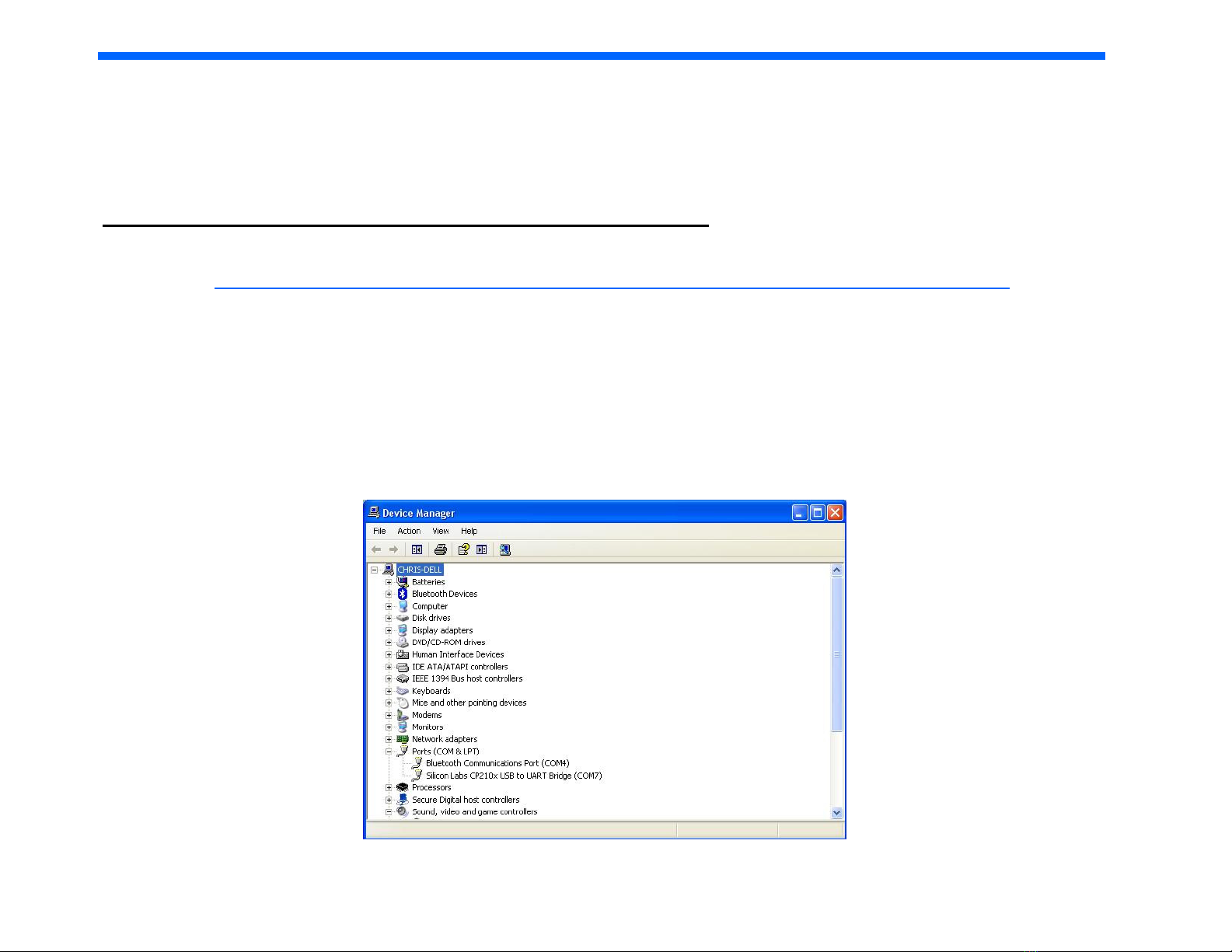
- You now must access the Windows Device Manager. This processes can vary depending on the version of Windows in
use, but typically it is found in the Control Panel. Then click on “System.” On the tabs across the top, click “Hardware”
and then “Device Manager” This will bring up a list, find “Ports (COM & LPT)” and click the plus (+) next to it. You
should then find a device called “Silicon Labs CP210x USB to UART Bridge” with a COM number listed next to it. This
number will change on all computers, but take note of this number.
CONTINUED ON NEXT PAGE
Page 20

19
Wave Launch Processor
- Go back to the XConsole software. At the top of the screen click “Setup” then “Port Connections” This bring up a new
dialog box. Select the COM port number you obtained from the device manger and click “OK.” The software will warn
you that you must restart the software for your changes to take effect.
- Restart the XConsole software. This time, when it asked “Do you want to connect to the device?”, answer “Yes”.
- You should now be connected to the device and ready to use.
Room Equalization
Before making adjustments with your processor, a basic understanding of parametric and graphic equalization is needed.
Parametric filters allow you to control the three primary parameters of a useful band-pass filter. These parameters
are amplitude (boost or cut), center frequency (pitch) and bandwidth (tonal range). Bandwidth is typically labeled "Q" on the
unit, which stands for Q factor. The amplitude of each band can be controlled, and the center frequency can be shifted, and
widened or narrowed.
Simpler graphic filters are fixed in frequency and bandwidth, so the music spectrum is divided into uniform third-octave spacings.
Page 21
20
Wave Launch Processor
Making Adjustments with Wavelaunch Processor
After installing the included software, connect the processor to the computer via a USB cable.
Launch the XConsole software.
When asked if you want to connect to the device, click yes.
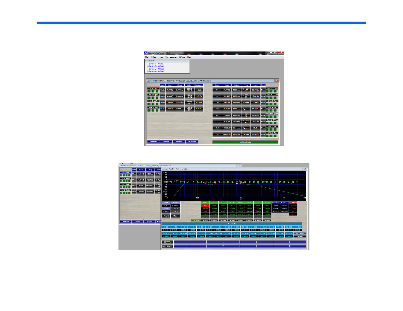
In the Device List, click on the device that is connected. This will launch the program that is currently on the processor.
Page 22
21
Wave Launch Processor
In the Device List, click on the device that is connected. This will launch the program that is currently on the processor.
Adjustments to the processor can be made to “Input 1: Left” and “Input 2: Right”.
Clicking on “In 1: Left” opens the controls for the Left speaker.
In this window, you are presented with 31 channels of graphic EQ and 8 channels of parametric EQ.
Page 23
22
Wave Launch Processor
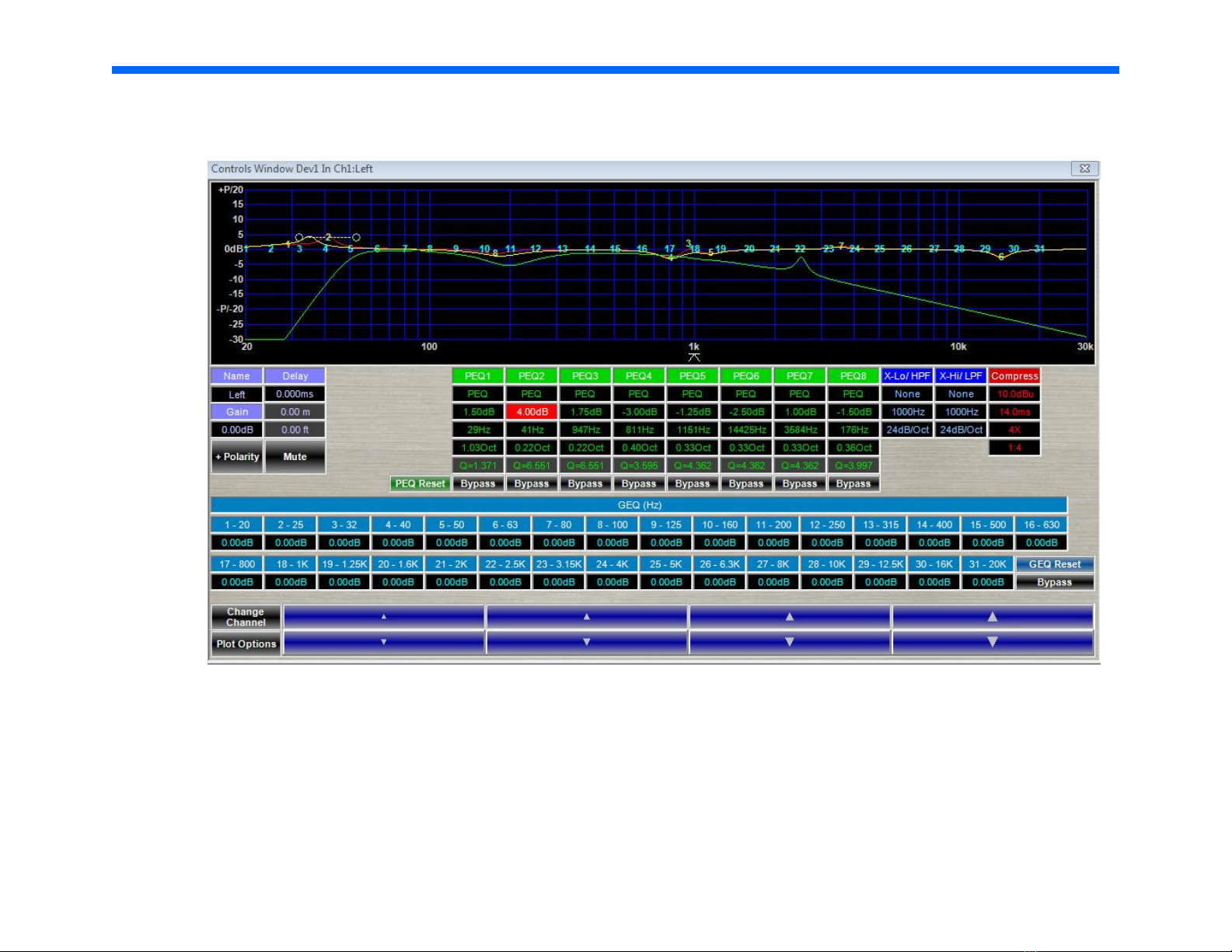
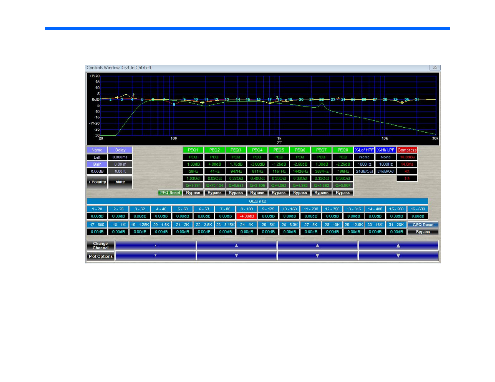
Making a boost with the parametric EQ
In this example, we have selected Parametric EQ 2 (PEQ2) by clicking in its box, which will turn red to indicate your selection.
Once highlighted, locate the blue boxes with up and down arrows, at the bottom of the interface. These arrows are used to in-
crease or decrease the gain, frequency and Q of the selected parametric EQ. This column shows a 4.00 dB boost at 41 Hz with a
Q of 6.551. A larger Q affects a narrow range of frequencies, while a smaller Q affects a broader range of frequencies. We can
adjust gain, frequency and Q by clicking in the corresponding box. Once highlighted, locate the blue boxes with up and down ar-
rows, at the bottom of the interface. These arrows are used to increase or decrease the gain, frequency and Q settings.
Page 24
23
Wave Launch Processor
Making a cut with the graphic EQ
In this example, we have selected Graphic EQ 8 by clicking in its box which will turn red to indicate your selection. Once high-
lighted, locate the blue boxes with up and down arrows, at the bottom of the interface. These arrows are used to increase or de-
crease the gain of the selected graphic EQ. This column shows a 4.00 dB cut at 100 Hz. Only gain is adjustable in the graphic
EQ section because graphic equalizers have a fixed frequency and Q.
After adjusting the left speaker, you may close the window, and click “Input 2: Right” to make adjustments to the right speaker.
Page 25

24
Wave Launch Processor
Adjusting using the EQ plot
Adjustments made to both the parametric and graphic EQ are reflected in the graph occupying the upper portion of the screen.
You can select them by clicking on their number, and dragging up to boost, and down to cut. Dragging to the left decreases the
frequency, while dragging to the right increases the frequency.
Recommendations
Boosts greater than 6 dB can result in ringing, driver overload, or mechanical buzzing.
Boosting and cutting with a smaller Q will affect a broad range of frequencies, and can be helpful for brightening an otherwise
dull recording.
Boosting and cutting with a large Q will affect a narrow range of frequencies, and is useful for making precise adjustments.
For the Ambitious: Technical measurements
We highly recommend free measurement software, Room EQ Wizard. This software allows you to measure the in room response
of your system. While we obviously cannot provide the technical support for this software, all one needs is a calibrated microphone and a soundcard with microphone preamp and you are off and running.
http://www.hometheatershack.com/roomeq/
Page 26
25
Continuing the Pursuit of Perfection
(Legacy Air Motion Ribbons)
LEGACY Audio has been benefiting from low mass ribbon and leaf drivers since 1984. I have a col-
lection of ribbon tweeters from the world over and always loved the way good ribbons reproduced
the swishing sound of brushes on a snare- and the simple honesty in the reproduction of strings
without imparting an edgy ringing effect found in most tweeters. There’s just something right about
the sound – like a C12 mic capsule. If one could increase the dynamics to natural levels and extend
the range of ribbons without beaming undesirably, the benefit would be considerable musically.
I have always been a proponent of low mass, high acceleration drive elements. The acceleration
capability of the drivers ultimately determines the transient or waveform tracing capability of the
loudspeaker. To build a better speaker, one MUST first acknowledge that loudspeakers are dreadfully slow by nature. Their responsiveness lags the electrical waveforms settling time
magnitude
phragm.).
Typical of transducers (devices that convert one form of energy to another), speakers are also
tremely
phase motion.
For these two reasons I have been working with speaker driver motors with magnetic field strengths
as high as 2 Tesla (60,000 times the field strength of our planet Earth) to overcome these limitations. With such field strength, greater levels of articulation are possible at the lower limits of a
transducer. For example, the reproduction of a simple strike of a heavy anvil will reveal tones that
are richer, darker and more complex than otherwise possible.
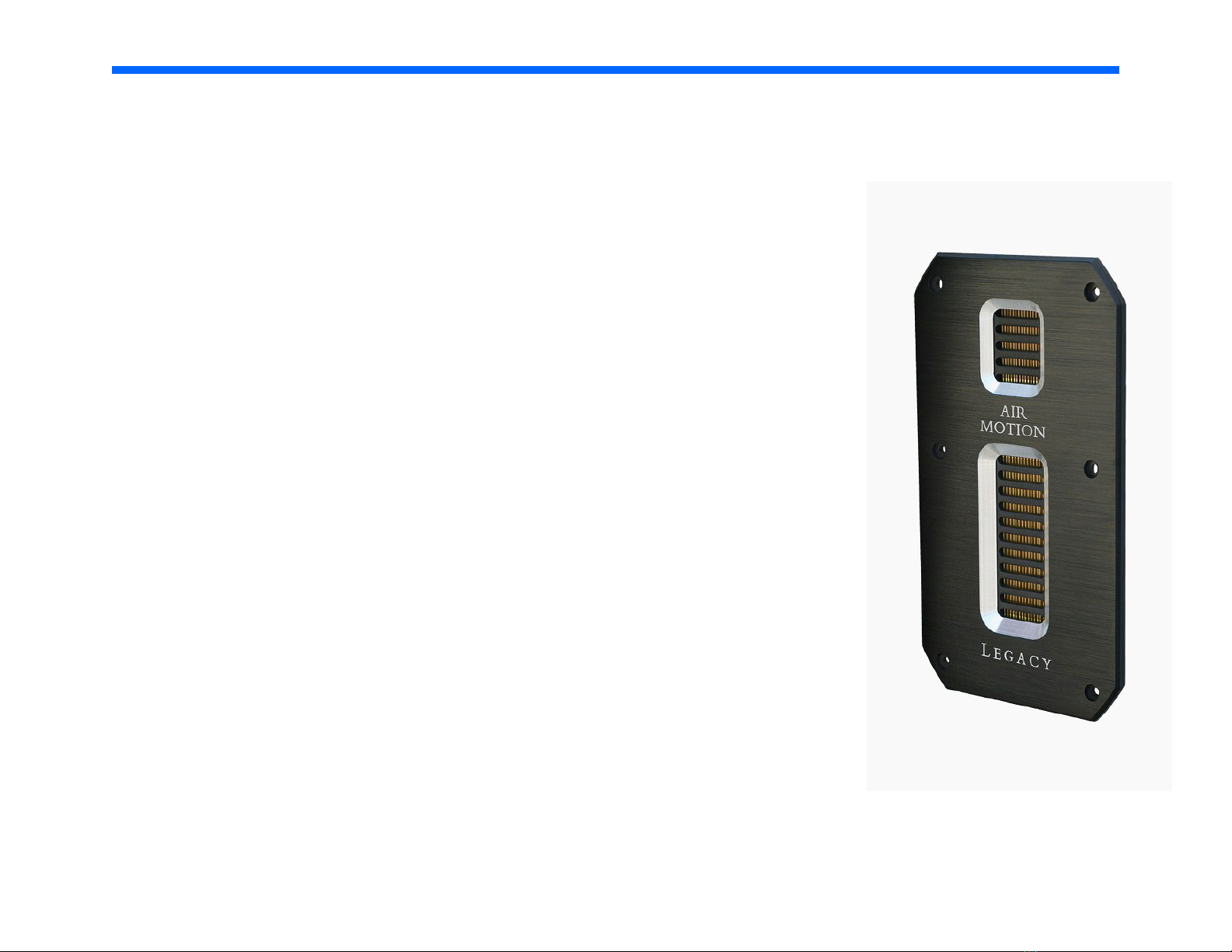
In 2006 Legacy Audio introduced our first air motion transducer; a modernized version of the AMT
tweeter developed by Oskar Heil in the 1970s. Legacy’s first version utilizes a folded Kapton (not
mylar) diaphragm and R45 neodymium wafers instead of ceramic magnets. The result was higher
efficiency and greater power handling. This translated to significant gains in dynamic range and
reduced distortion. We soon adapted an existing 4” planar ribbon (the one with the round faceplate)
to work in conjunction with this tweeter to facilitate the voicing of the hand-off to our 7” driver.
(Logically so, if one contrasts the mass of an electron to the mass of a speaker dia-
inefficient -wasting more than 98% of their input power in the form of heat and out of
by orders of
ex-
Page 27

26
Continuing the Pursuit of Perfection
(Legacy Air Motion Ribbons)
The recent Aeris loudspeaker development gave me the opportunity to tool a new AMT folded ribbon tweeter to integrate with the
smoothest high efficiency 8” midrange built to date. I have yet to find a driver to challenge it. This silky 8” mid has a range of 7 octaves
with nary a wrinkle in the response, yet a sensitivity of 98 dB. My initiative of providing a 4” AMT that could compliment these capabilities
was met with the challenge of accordion-folding sixteen square inches of Kapton into the 4” long, 1” wide chamber. Neodymium again was
employed to provide the flux density required. But the solution was made even more elegant by mounting the new 4” ribbon on the same
faceplate as its complementary 1” AMT ribbon super-tweeter. The results were more uniform dispersion and tremendous attack. Treble
now had
effortless way it forcefully squeezes out acoustic energy is readily verified by placing ones hand over the driver faceplate and feeling the
suction against your palm (nope, you won’t hurt it). These new drivers may be refined, but are equally rugged.
I am fortunate to have chosen loudspeaker development as my life’s work. It has utilized my chemical engineering, physics and mathematics background almost daily. It has offered moments of both humility and glory, but most gratifying is the reward of continual, stairstepped successes even after 30 years. I sense that this is a never ending staircase to be followed for generations as we asymptotically
approach unattainable perfection.
Bill Dudleston, Chief Designer, Founder of Legacy Audio
weigh
t instead of tizz. A natural fullness in the treble is exhibited that reminds us why we love high-end audio so much. The
Page 28
27
Specifications
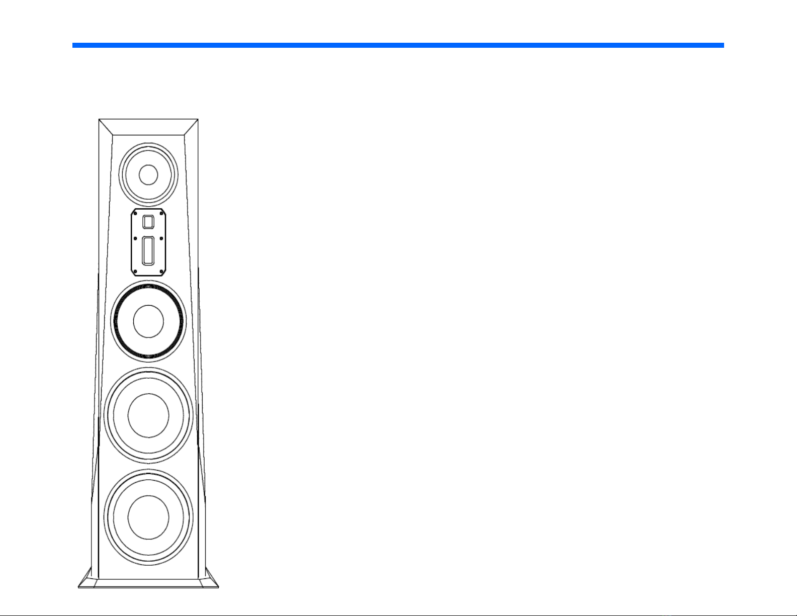
System Type: 6 drivers, 4.5 way
Tweeter: Dual Air Motion Tweeter System— 4” AMT Tweeter,
1” AMT Super Tweeter
Midrange: 8" Titanium encrusted, Accordion Edge
Midwoofer: 10” Accordion Edge
Woofer: 2 x 12" spun aluminum diaphragm, rubber
surround, total enclosed neo motor, long
throw suspension, with cast frame
Frequency Response:
Impedance: 4 Ohms
18Hz – 30 kHz
Recommended Amplification: 60-500 Watts
Internal Amplification: 2 X 500 watt ICEpower
Crossover Frequency: 80, 2.8K, 8K
Cabinet Dimensions (HxWxD): 58” X 14.5” X 16”
Base Dimensions (HxWxD): 1” X 19” X 15”
Weight: 171 lbs each
®
modules for bass section
Page 29

28
Wavelet Upgrade for Aeris
Wavelet is a control preamp, a premium DAC, a digital crossover with time alignment for each driver section and an acoustic correction system
that will literally ‘learn’ your room.
True digital flexibility
SPDIF (opticalTosLink, coaxial): up to 96kHz/24bit
USB: All file formats up to 96kHz/24bit are sent directly from the PC to the Wavelet without any conversion. Higher resolution files such as PCM
and DXD can be readily played back using software such as J-River (select: Greater than 192kHz under DSP STUDIO.)
Analog Friendly
Already have a favorite DAC with a volume control? How about a big vinyl collection? Analog lovers can take advantage of balanced XLR or
unbalanced RCA inputs without concern of digital artifacts. An apodizing circuit corrects for the pre-ringing native to CODECs. Wavelet has
adequate headroom to handle these higher level signals while functioning as a crossover and compensating for room resonances. Wavelet
processes at 56 bits of depth in a domain more than one trillion times finer in resolution than that of a 16 bit CD.
The Wavelet is by design upgradable. The unit can download firmware updates directly when you choose.
While the Wavelet offers high quality/ low noise balanced inputs to accept the analog output from any SACD player, ideally one would instead
stream PCM versions of these files to the processor via the USB input. Within software such as J-River, the 1 bit DSD is converted to 64 bit PCM at
1/8 the sample rate. The total amount of data from this conversion grows by 8x, so the process is effectively lossless / perfect. The conversion is
necessary as DSD is inefficient for sophisticated DSP operations.
Page 30

In the J-River software this configuration is located in the Player -> DSP Studio - Output Format section. Setup all sample rates up to and including
29
96kHz to “No Change”. Then set input 176,400 to output 88,000, 192,000 to 96,000 and greater than 192,000 to 96,000. DSD is converted
automatically in the software to PCM. Once you have PCM, it will be 64bit @ 352.8 kHz for DSD, and 64bit @ 705.6 kHz for DSD 2x. The option
'Greater than 192kHz' in DSP Studio > Output Format should be selected.
Why PCM?
This is a format issue and has nothing to do with the Wavelet in particular. As professional studios rely on PCM based equipment such as Pro Tools
to mix, pan and balance recordings, the vast majority of SACDs are in fact mixed in PCM, or mixed analog and recorded in PCM. They may then be
converted to DSD for SACD mastering stages. The PCM format is far more efficient where DSP is in use. Recently a newer studio format, DSDwide, has been developed to allow DSP operations that can be down-converted to DSD for SACD production. Pro DAWs such as SADiE are now
using this technology.
PCM is the universal format of studios and digital signal processing. Most
recordings released in other formats were actually recorded in PCM format.
Page 31
30
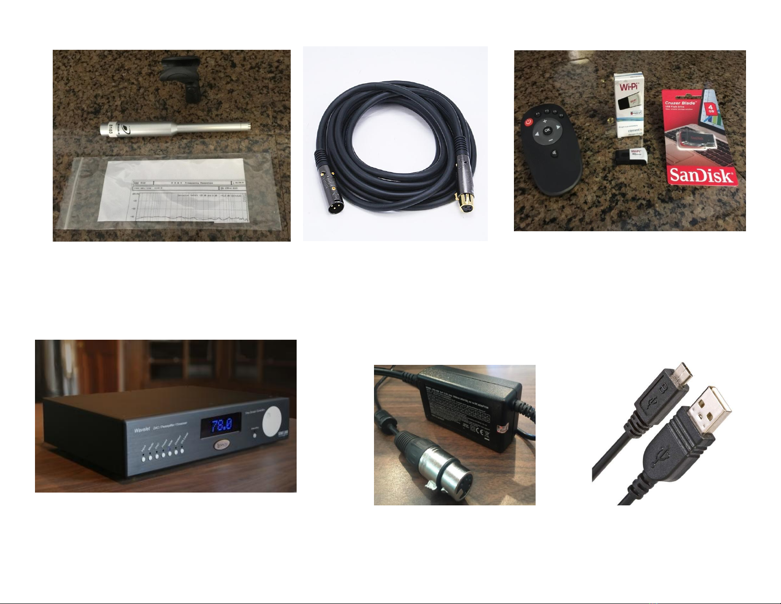
Inside the Wavelet processor carton packaging you’ll find a hard-case containing a measurement microphone, a 25 ft. XLR
cable and a mic calibration plot. At the opposite end of the carton you will find a power supply with a five pin locking
connector and its 115 V AC cable, a compact remote volume control, a Wi-Pi network connector and a SanDisk USB memory
stick. Also included is a micro USB cable to connect your computer or media server to the Wavelet.
Page 32
31
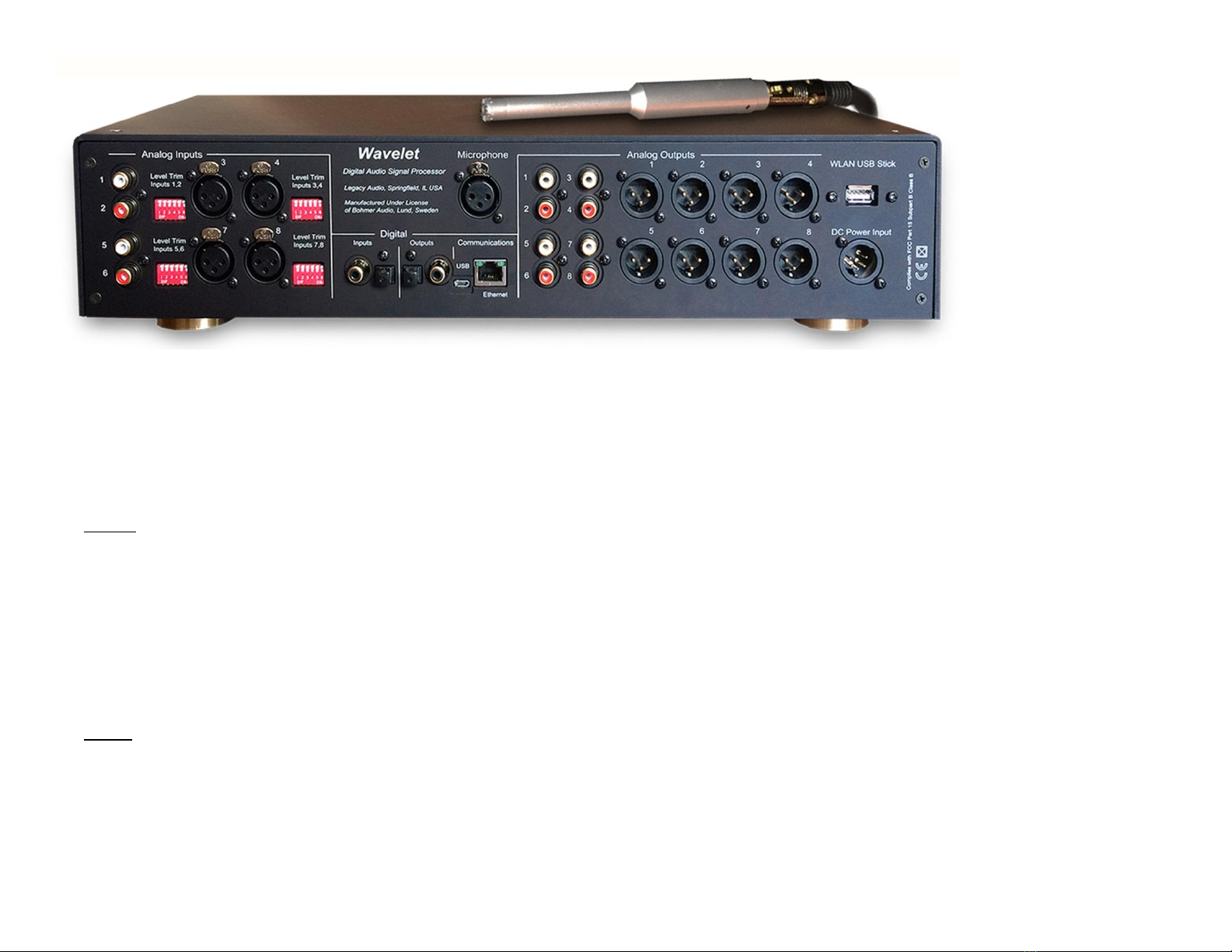
Wavelet Preamplifier/DAC/Crossover/Room Correction Processor
Inputs
Analog
Two pairs of Stereo balanced inputs on XLR connectors.
Input sensitivity without attenuation 0 dBFS*1 = 1 dBV*2, input impedance 20 kOhm.
Analog attenuation available in three steps of -3 dB, -6 dB and -12 dB for an input sensitivity of respectively 0 dBFS = 4 dBV, 7 dBV or 12dBV.
Two pairs of Stereo unbalanced inputs on RCA connectors.
Input sensitivity without attenuation 0 dBFS*1 = 1 dBV*2, input impedance 100 kOhm.
Analog attenuation available in three steps of -3 dB, -6 dB and -12 dB for an input sensitivity of respectively 0 dBFS = 4 dBV, 7 dBV or 12dBV.
One XLR Measurement microphone input, 48 Vdc Phantom power.
Digital
Asynchronous USB audio, 24 bit, 44.1 – 96 kHz, PCM up to 352.8 kHz.
SPDIF, 24 bit, 44.1-192kHz
TosLink, 24 bit, 44.1-96kHz
Page 33

Outputs
32
Analog
8 balanced output channles on 8 XLR connectors. 0 dBFS
*1
= 8 dBV
available through internal jumpers offering 0 dBFS = 14 dBV
8 unbalanced output channels on 8 RCA connectors. 0 dBFS
*1
= 8 dBV*2, 33 Ohm output impedance.
Digital
SPDIF, 24 bit, 96 kHz
TosLink, 24 bit, 96 kHz
Control Interface
Ethernet, TP-Cable & WLAN
Processing
DSP
Analog Devices, internal processing sample rate 96kHz, bit depth 56 bits
The Bohmer Correction is a loudspeaker in-room energy-time alignment that optimizes the loudspeaker room acoustic transfer function in
both frequency and predominantly time domain. Working with revolutionary new algorithms is starts with a psychoacoustically based
measurement method. Alignment errors are then optimized individually, not resorting to the common crude bulk correction over the entire
frequency spectra. The Algorithms use psycho acoustic reasoning for alignment and correction of the loudspeaker room transfer function.
The correction improves sound quality in the whole room, provides improved transient response, clarity & soundstaging and gives a relaxed
sound without rough edges or any booming.
Physical
*2
, 33 Ohm output impedance. An analog output level increase of 6 dB is
Dimensions
445 mm W x 301 mm D x 95 mm H / 17.52” W x 11.85” D x 3.74 H Weight 6.1 kg / 13.5 lbs
Page 34

Wavelet Speaker Connections for Aeris
33
Let's first connect the outputs of your Wavelet to your Aeris speaker and external amplifier. These outputs are all that are necessary to setup your
Wavelet with Aeris. The input connections from your Player, Transport, Preamp etc. can be connected after setting up your Wavelet.
Wavelet can output both balanced XLR and RCA, offering maximum connectivity flexibility. We recommend using XLR if your amplifier supports it.
Wavelet processor outputs:
1 Left Aeris speaker bass amplifier
2 Left midrange/treble amplifier
5 Right Aeris speaker bass amplifier
6 Right midrange/treble amplifier
Page 35

34
Optimizing Analog Outputs
When using the analog inputs it is useful to optimize the input levels according to how they are being used.
This will maximize the signal to noise ratio and provide optimal gain while preventing distortion from input
overload.
Outboard DAC to Wavelet Analog Inputs Using Wavelet as your Preamplifier
The Wavelet has adequate internal gain for virtually any outboard DAC ouput. In some cases you may wish to
decrease the input sensitivity of the Wavelet to accommodate an external DAC with high output level,
especially if your are using one with a volume control. Each stereo pair of analog inputs of the Wavelet can be
adjusted downward in -3, - 6, or -12dB steps as shown below. The goal is to set the analog channel’s input
sensitivity so that adequate volume level is achieved from your system without any audible clipping of the
inputs. When adjusted properly, the Wavelet’s blue front panel display will usually be in the range of 85dB for
average listening levels. When using the Wavelet’s digital inputs such as the SPDIF from a CD transport,
adjustments are not required - thus there are no provisions for such. Some computer hosted media software
may introduce an extra level control stage to the USB output. In this case it is best to configure the software
settings so a typical listening level is accomplished with Wavelet displaying 85dB.
Outboard Preamp Driving Analog Inputs Using Wavelet for Crossover/Room Correction
If you are relying on an external preamplifier to provide the both the master gain and level control into the
Wavelet, you will need to optimize the inputs sensitivity of the Wavelet’s analog inputs. The key is be certain
that the highest volume from the preamp does not overload the analog inputs. We recommend beginning
Page 36
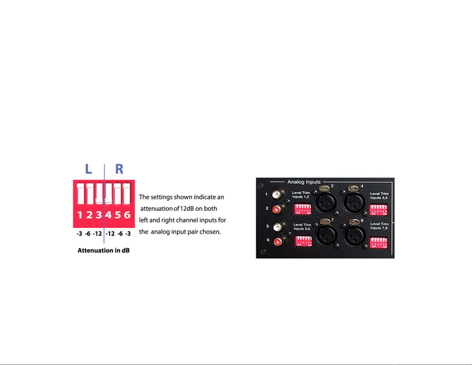
with the -12dB setting initially as shown below. Further attenuation of -3, -6dB is available if needed. While
35
you can also further reduce the volume setting from your preamp, the goal is totally avoid clipping at all levels.
Again try to establish a Wavelet level setting of about 85dB for typical listening. With a little care you will
have minimized your noise floor and prevented input saturation. Rarely does the Wavelet need to be set
above 90dB when optimizing to the volume settings familiar from your preamplifier.
Rear Panel View of Resistive Switches
Page 37

36
Ready to take control
of your Aeris with
Wavelet?
Page 38

Introduction
37
Wavelet features can be remote controlled via iPad, iphone, or other mobile device. In order to perform room correction it is essential that you
connect the unit to the internet. To maximize enjoyment, we recommend dedicating one of these handheld devices to your music system, thus
keeping your phone calls, and messages from interfering directly with your listening and control experience. If you don’t have an extra device,
consider picking one up used. We love controlling the system with an iPad Mini sized screen.
What happens if my internet goes out? Don’t worry- the Wavelet remote functions continue to work and room correction settings are maintained,
even without an internet connection. An internet connection is only necessary for the initial setup and all settings are retained inside of Waveleteven if the internet is out your system will work as designed.
Page 39
Wavelet WiFi Internet Setup
38
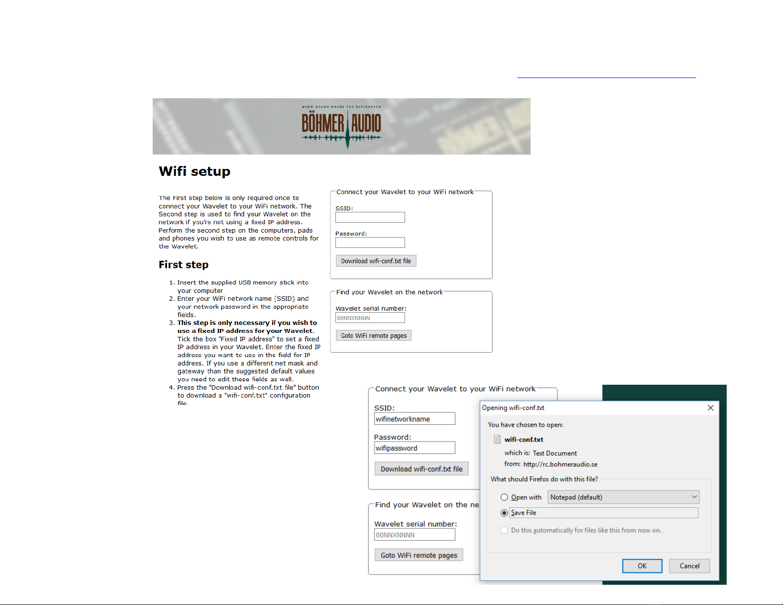
1. To connect your Wavelet to the internet, please open a browser on your PC or Mac and visit http://bohmeraudio.com/setup.html
a. Enter your SSID- this is your Wifi Network name.
b. Enter your Wifi Network Password and click “Download
wifi-conf.txt file”
c. Insert the included SanDisk USB memory stick into your
computer.
d. When prompted to “Open” or “Save File” choose “Save
File” click “OK”.
Page 40
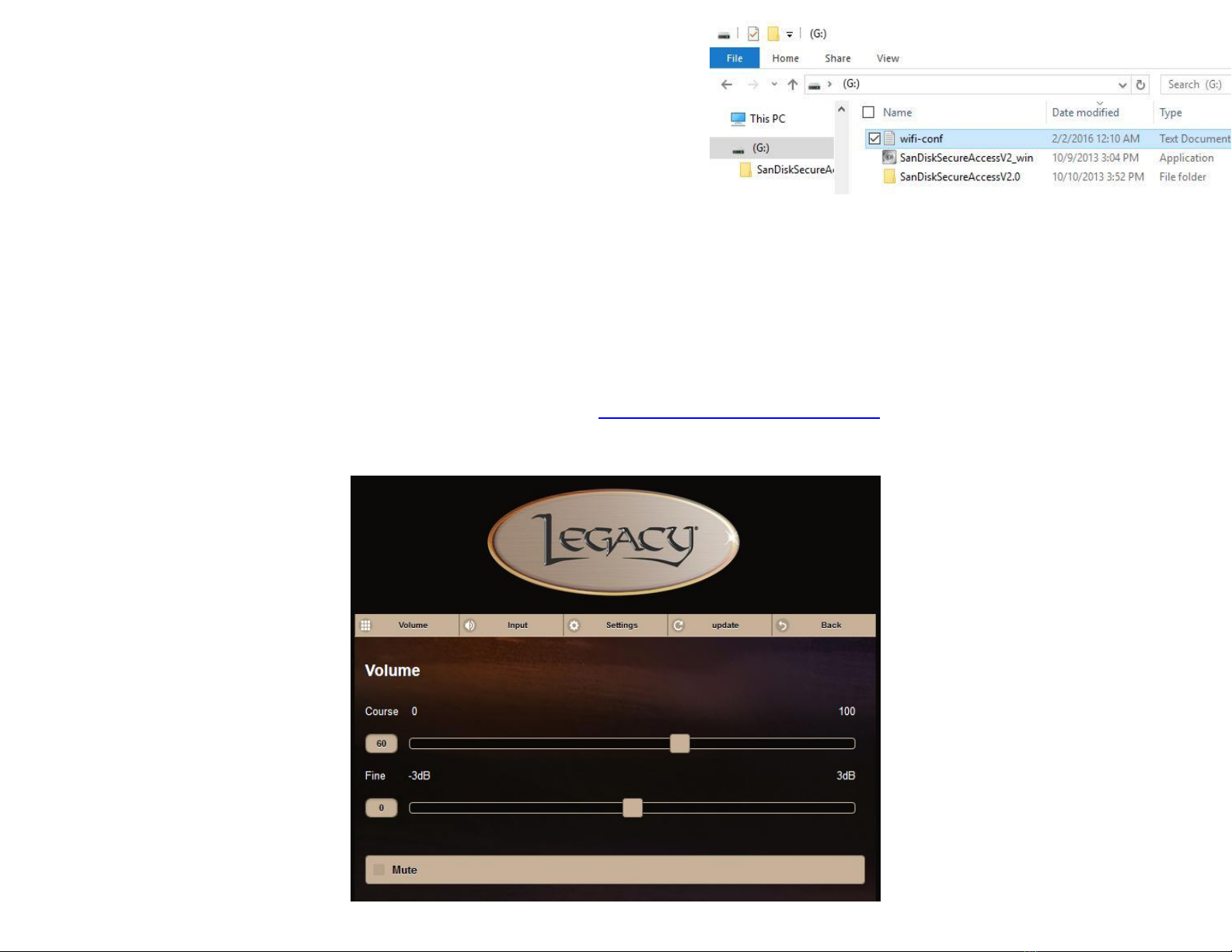
e. Copy the “wifi-conf.txt file to the root directory of the SanDisk USB memory
39
-Volume
stick. Depending on your browser settings, you might find the file downloaded
to your Desktop or Downloads folder. After locating it, right click the file and
choose copy. Navigate to the SanDisk USB memory stick and paste the file into
the main ”root directory” so that when you click on the SanDisk USB drive
from your computer, the file is visible and not placed within another folder.
You may now remove the SanDisk USB memory stick from your computer.
f. Power off your Wavelet. Insert the SanDisk USB memory stick into the port located at the back of Wavelet labeled WLAN USB Stick. Power
Wavelet back on and wait 1 minute. The system is saving your wifi network to memory.
g. After 1 minute, power Wavelet off, remove the SanDisk USB memory stick and insert the WiPi WiFi Stick into the port located at the back of
Wavelet labeled WLAN USB Stick.
h. Turn Wavelet on and wait for 1 minute- confirm that the Blue LED on the WiPi WiFu Stick is lit or lit with occasional flashing.
2. Now we will open the WiFi remote. Please use the device you wish to control Wavelet with- we recommend an iPad or iPhone. Any smart
phone or smart device will work.
a. First, make sure that your device is connected to the same WiFi network your Wavelet is connected to. (On Apple devices, click
Settings, Wi-Fi, and choose the appropriate network)
b. In your internet browser (Safari on Apple devices) enter http://bohmeraudio.com/setup.html in the address bar.
c. Your Wavelet Serial Number is located on the back of the Wavelet, on a sticker near the USB port. Enter it into the box labeled
“Wavelet serial number” without any spaces and with capitalized letters. Click ok and click “Goto WiFi remote pages”
Page 41
40
You do NOT need to re-enter your Internet information, only the serial number
-Volume
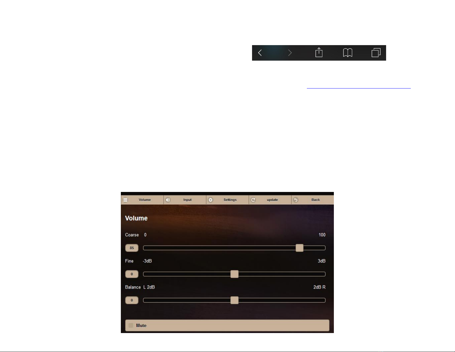
d. You will now see the Volume Control Page- please bookmark this page for future use. The bookmark button on Apple devices is the
square and arrow at the bottom of the screen that looks like this:
Firefox users can click the Star to bookmark their remote control.
TIP You can always return to your remote by visiting and entering your serial number http://bohmeraudio.com/setup.html
e. Confirm your device is talking to Wavelet by adjusting the volume slider from your device and watch the Wavelet volume change
remotely. Congratulations! You can also control your Wavelet from additional devices by repeating Step 2 for each device you wish
to use.
Volume Adjustments Before Running Room Correction on Your Wavelet
1. To prepare for running room correction, please set the Wavelet volume to 85. The “Fine” slider is useful for making precise
adjustments. Touch the ”Fine” slider and move it to the far right- notice when you release, the volume increases by 3dB, and
when moved slightly to right, increases by .1 dB increments. You can use the Coarse adjustment is useful for making large
adjustments. The “Balance” slider can be used to adjust the center image of your speakers. At the extreme left or right, the slider
provides a 2dB boost. Please note that the balance should be set to 0 for running room correction.
Page 42
41
-Settings
-Settings
-Setup
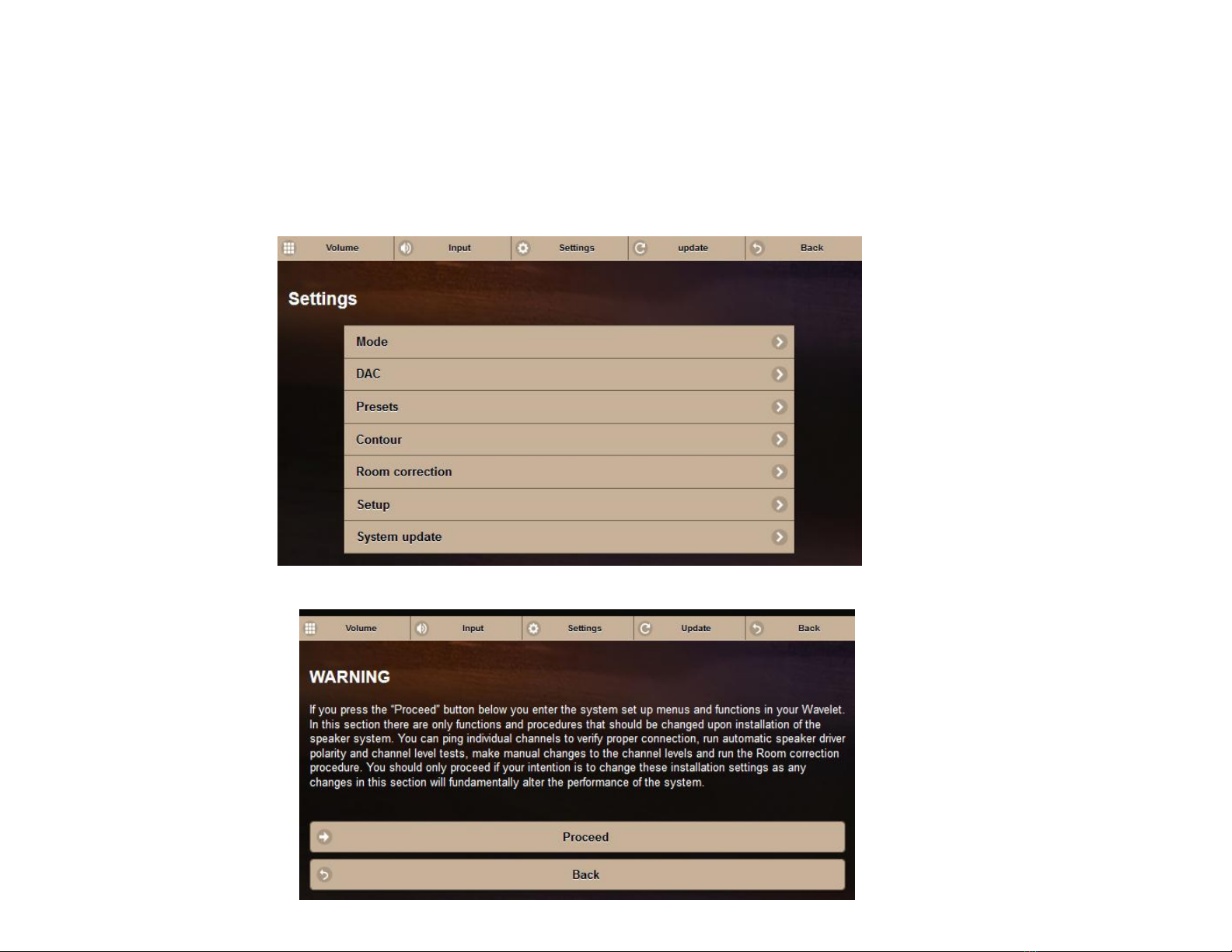
TIP On any page of the Wavelet, click the “update” button at the top to refresh your handheld device and display the settings that are inside
Wavelet.
a. First we will verify that all connections are correct by clicking the “Settings” button at the top. Then choose “Setup” and Click Proceed
b. Choose “Setup” and click “Proceed”
Page 43
42
-Settings
-Setup
-Proceed
-Settings
-Setup
-Proceed
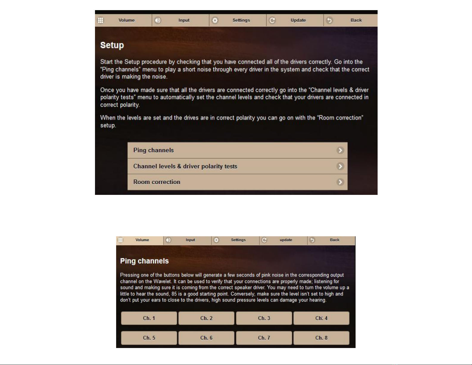
-Ping channels
c. Select “Ping channels.” You can now follow the on screen prompt and click the corresponding channels to confirm that sound is coming
from the appropriate drivers. Please refer to the connection section of this manual for appropriate channel connections.
Page 44
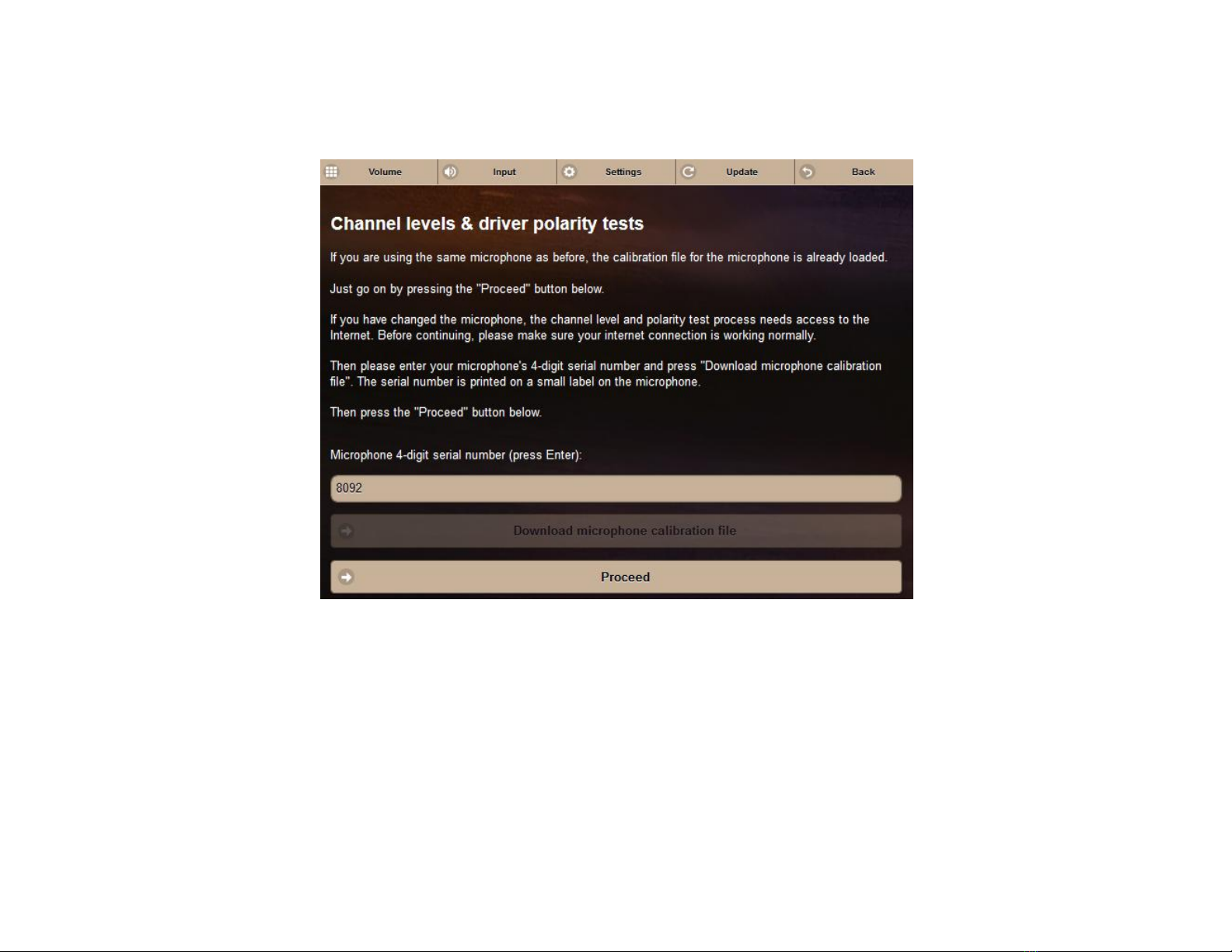
d. Wavelet is capable of setting the channel levels for you- this is useful for balancing your amplifier(s) with the internal amplifier(s). To do so,
43
-Settings
-Setup
-Proceed
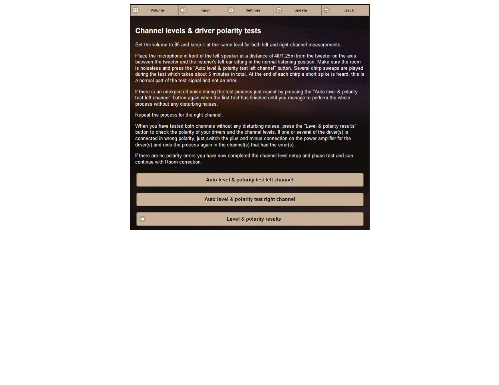
-Channel levels & driver polarity tests
click the back button and choose “Channel levels & driver polarity tests”.
e. Place the microphone that shipped with Wavelet at tweeter center height, 48” away from the left speaker, perpendicular to the speaker
baffle.
f. Your microphone has a 4-digit serial number on it, please enter it into the Wavelet app and click “Download microphone calibration file”.
g. Once it is downloaded, click proceed. (Note, if you have already downloaded the microphone calibration file, you will not need to download
it again.)
Page 45
44
-Settings
-Setup
-Proceed
-Channel levels & driver polarity tests
h. Follow the on screen prompts. With the volume set to 85, select “Auto level & polarity test left channel.”
i. If you receive a message that the levels are too low, first check that both ends of the mic cable are firmly docked and repeat the test.
Increase volume if necessary.
j. After completing the left measurements, move the microphone to the right speaker, keep the volume the same, and repeat step i for the
right speaker
Note: this process can take about 5 minutes per channel while Wavelet calculates the settings. Once they are set, Wavelet remebers the
settings even after power down, so you do not have to repeat this process.
k. You can view the results by clicking “Level & polarity results”. You have now completed the channel level setup and phase test and can
continue with room correction.
Page 46
45
-Settings
-Room correction
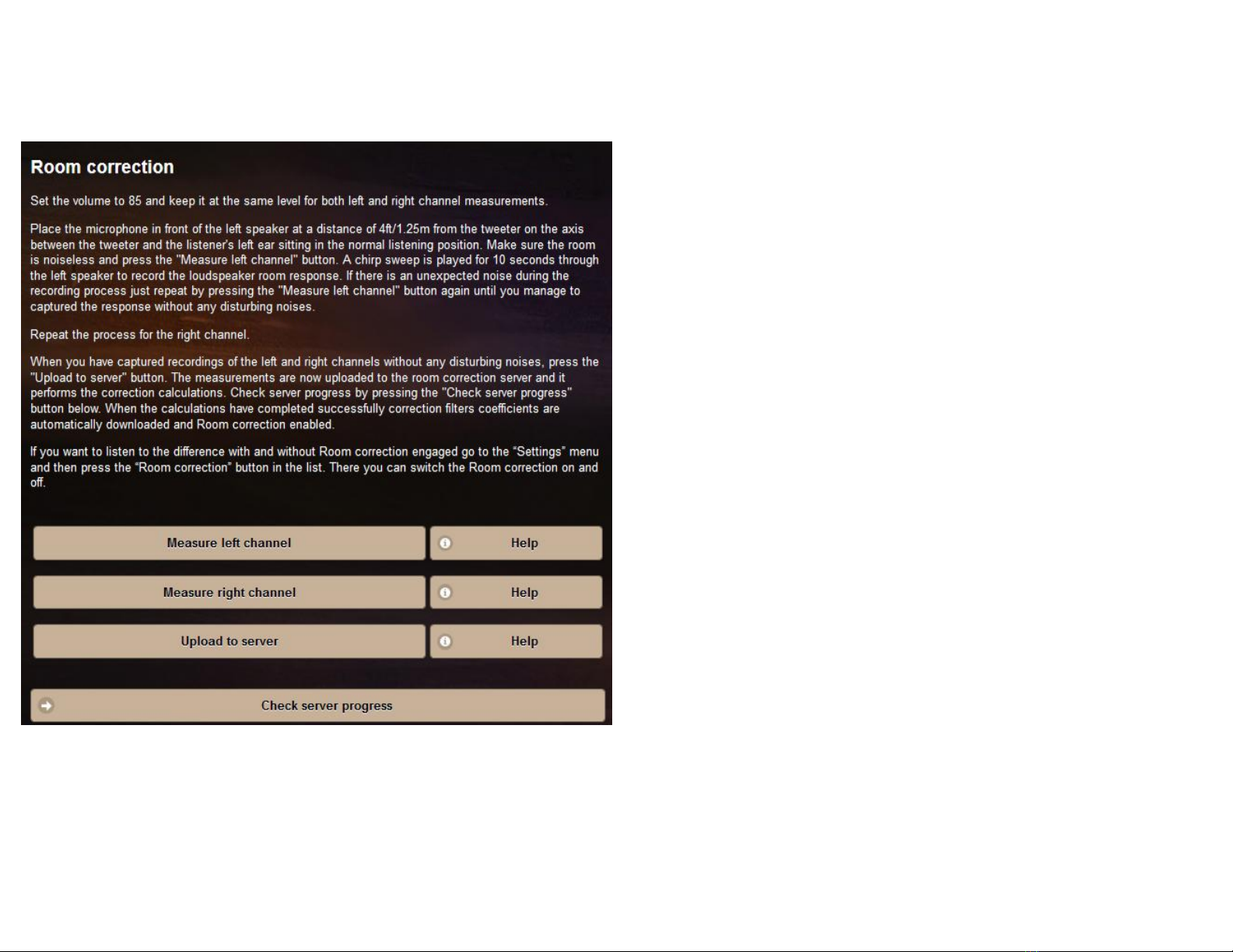
2. Click settings at the top of the screen, and choose “Room
correction”.
a. With the microphone at tweeter center height, 48” away from
the left speaker, perpendicular to the speaker baffle, choose “Measure
left channel”.
b. Please wait for the process which lasts about 10 seconds.
If there is an unexpected noise, please repeat the process by clicking
“Measure left channel” again.
c. Look at the bottom of the screen- if you see an error
such as “Volume too low,” please check the connections and/or
increase the level and try again.
d. This process may take 5-10 minutes. Please be patient,
you will be prompted when the process is complete.
e. If you receive an error message that the levels are too
low, please check that both ends of the microphone cable are firmly
docked, and repeat the process, raising the volume if necessary.
f. Repeat steps a-e for the right channel
g. Click “Upload to server”- this sends the measurements to the
room correction device which calculates the ideal settings for your
speakers and automatically sends them back to your Wavelet. You can
observe progress at the bottom of the screen. This process may take 510 minutes. You will be prompted when the process is complete.
Page 47
46
-Settings
-Room correction
-Settings
-Contour
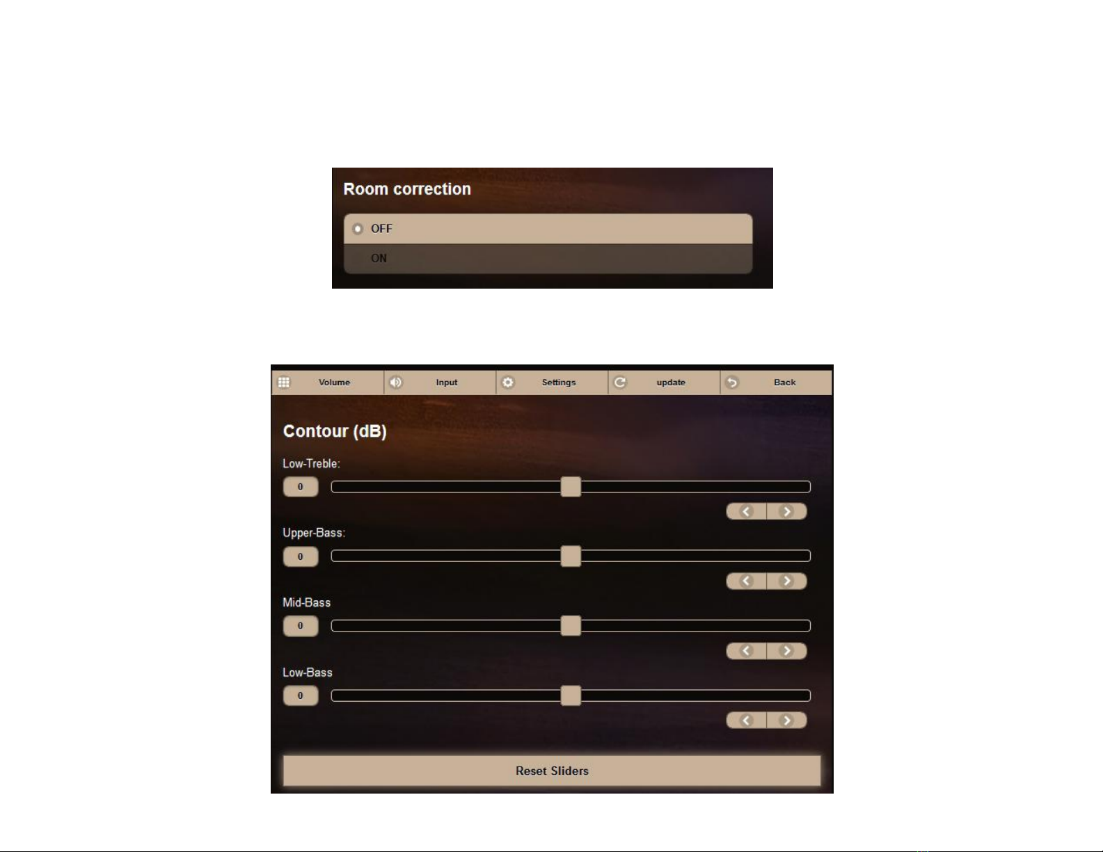
f. Upon completion, click the “Back” button at the top. Confirm that Room Correction is set to “ON”You are now ready to enjoy your
Wavelet system! You can turn the room correction on and off during your listening. Access the Room Correction by clicking
Adjusting your Wavelet
After room correction, you can further tailor the sound of your Legacy speakers in your room via the “Contour” page. Access this page by clicking
“Settings” and choosing “Contour”.
"Settings" at the top of the screen, and choosing "Room Correction"
Page 48

47
The sliders can be adjusted in the same way as the volume control- by placing a finger on the center slider. Moving to the right creates a boost
(more volume) and moving to the left creates a cut (less volume) in the given frequency band. A handy “Reset Sliders” button is available at the
bottom to reset the Contour Sliders.
TIP The most recent slider settings are retained permanently in the Wavelet memory- even if you turn the unit off, Wavelet will remember your
settings.
Page 49
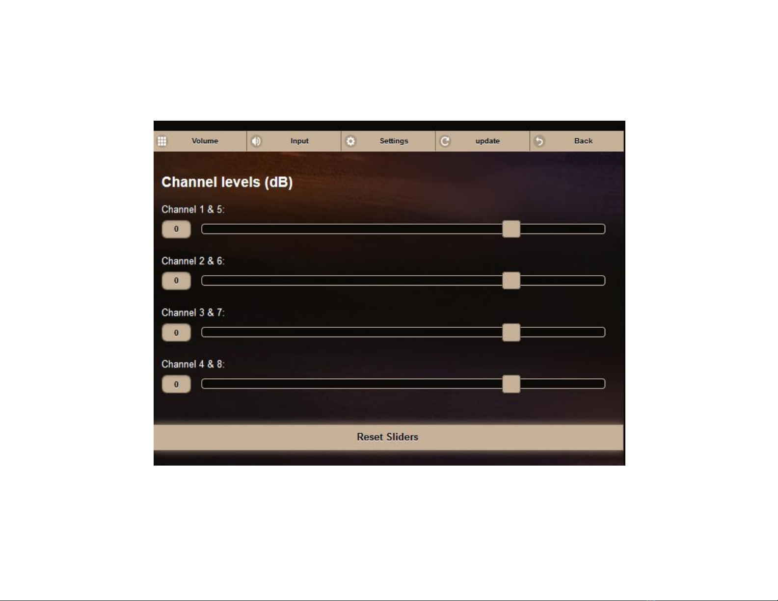
You can also adjust the output levels of the individual channels. If you performed automatic channel adjustment (as explained in this manual) you
48
-Settings
-Setup
-Channel levels
will have settings already applied. You are welcome to further adjust this, if you desire.
TIP This is useful if, for example, you are using stereo Legacy Audio subwoofers with Aeris on channels 3 and 7- you can use this slider to control
the volume of your subwoofers!
Page 50
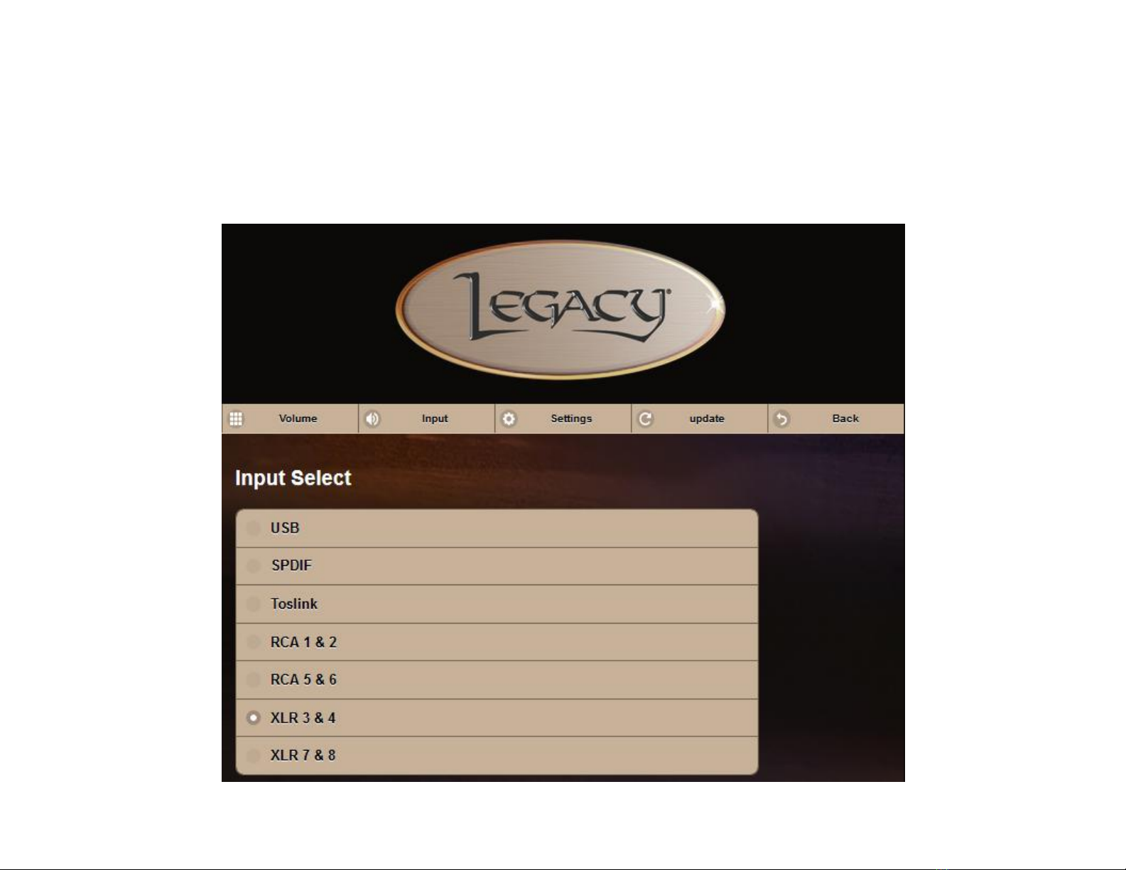
Input Selections
49
-Input
You can wirelessly switch between inputs on your Wavelet by selecting “Input” at the top and choosing your desired source. USB allows Wavelet to
connect to a computer and play back high resolution audio. USB, SPDIF and Toslink allow for digital connectivity and reduces the need for an extra
AD conversion- a valuable performance advantage.
4 pairs of stereo analog inputs allow Wavelet to easily interface with your preamplifier, transport or other devices- making it both flexible and
letting you retain all of the color you might enjoy from your gear- tube, solid state or digital.
Page 51
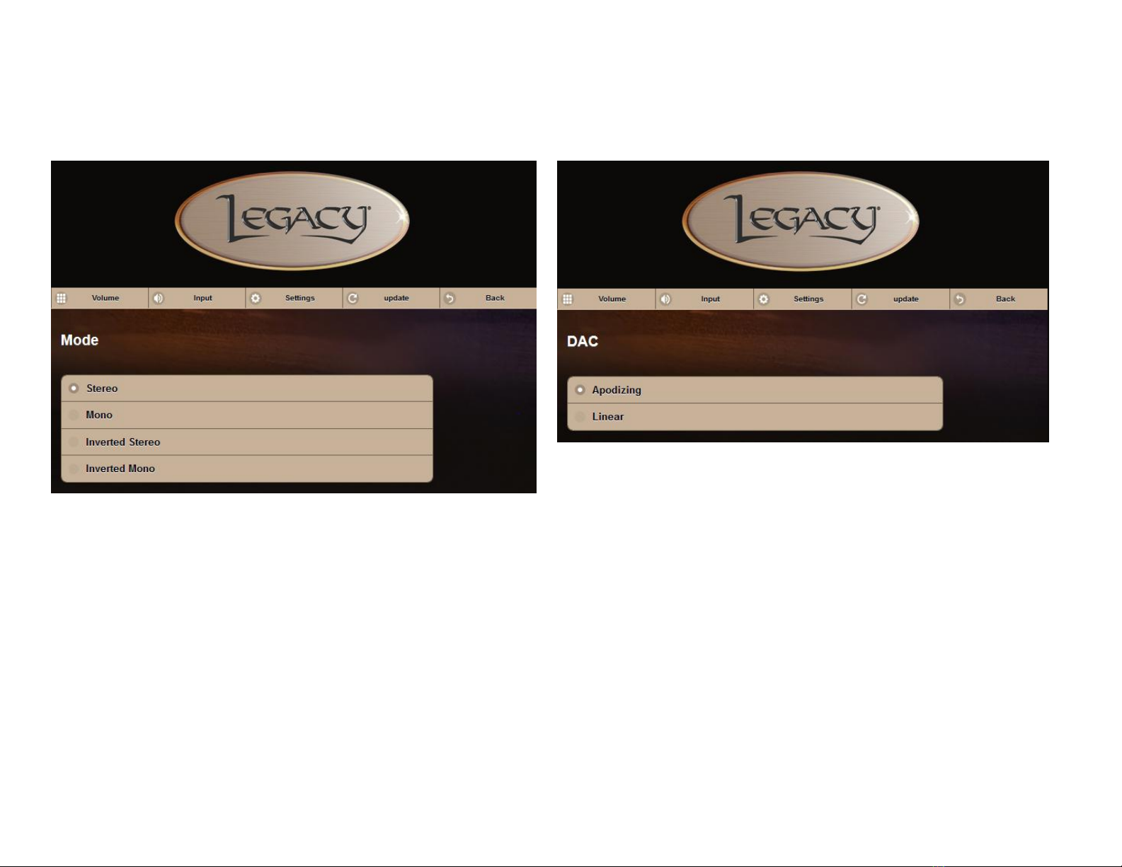
Mode & DAC Adjustments
50
-Settings
-Mode
-Settings
-DAC
Wavelet allows you to listen in Stereo, Mono and Inverted modes. You can access these settings by choosing “Settings” at the top and selecting
“Mode”
The Wavelet features an apodizing circuit that corrects for the pre-ringing native to CODECs. Analog lovers can take advantage of balanced XLR or
unbalanced RCA inputs without concern of digital artifacts. Turn on the apodization circuit by choosing “Settings” at the top, clicking “DAC” and
selecting “Apodizing”. “Linear” bypasses the apodization circuit.
Page 52
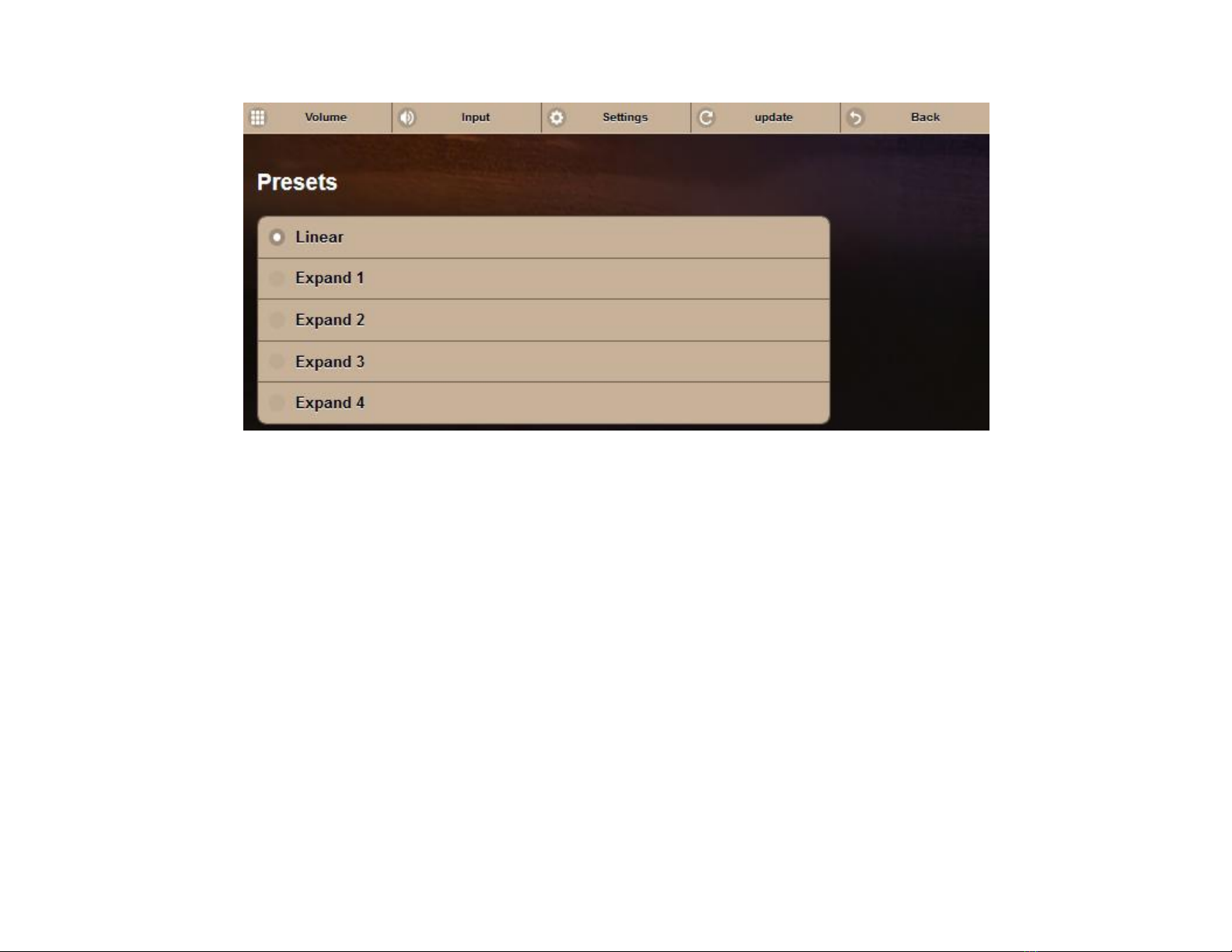
Presets
51
-Settings
-Presets
Wavelet features a number of presets to allow you further control of your listening experience. Access these presets by choosing “Setting” at the
top of the screen and clicking “Presets”.
Page 53
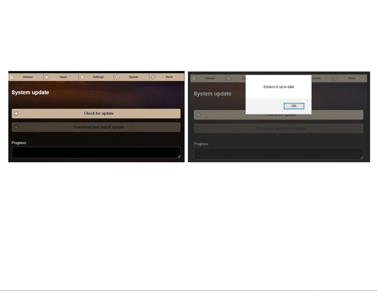
Updating the Wavelet System
52
-Settings
-System update
Wavelet is, by design, easily updated via the app. This allows the device to be updated with new added features as they are requested and
developed.
To check for updates, choose “Settings” at the top, select “System update” and click “Check for update”
If an update is available, you can click “Download and install update”. If the system is updated, it will display “System is up to date.”
Page 54
53
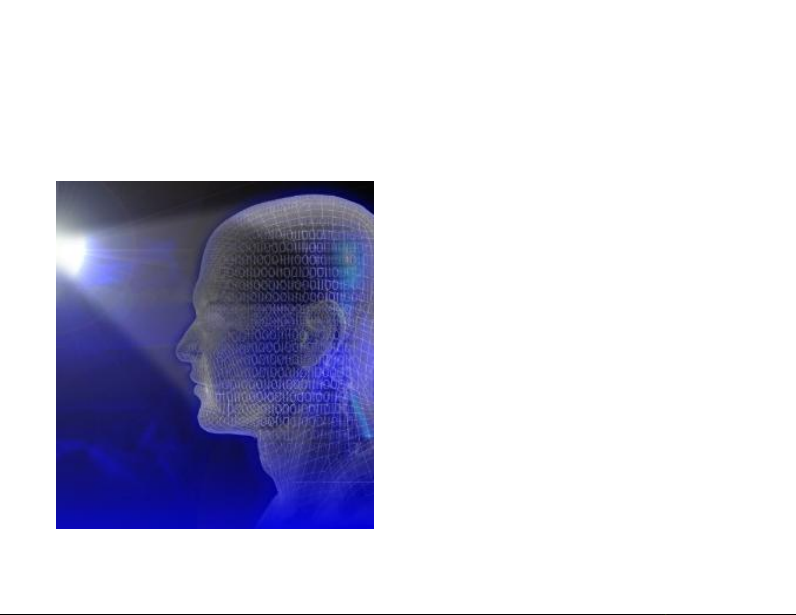
Achieving Ideal Imaging In The Room
Below about 1500Hz there is a phase difference between the sound waves entering the ears, thus
providing acoustic localization cues (interaural time differences, or ITD). At frequencies greater than
1500 Hz, the wavelength is shorter than the distance between the 2 ears, and phase sensitivity
diminishes. The brain now relies on acoustic head shadows produced across the face to provide level
differences to each ear (ILD) and cues for the localization
of this sound. If the speaker system projects sound onto
the room boundaries creating a diffuse field before it can
reach the listener directly, these fragile ITD and ILD cues
will be altered and scrambled.
The key to imaging is preserving the interaural time and
level differences. The shadowing to the far ear from the
source is quite fragile in a reflective environment.
Maintaining directivity in the speaker radiation pattern is
essential to preserve this content. Legacy V, Whisper,
and Aeris each offer unique directivity control to provide
greater clarity, better localization and resonance
reduction.
Page 55
54
Why is Room Correction Necessary?
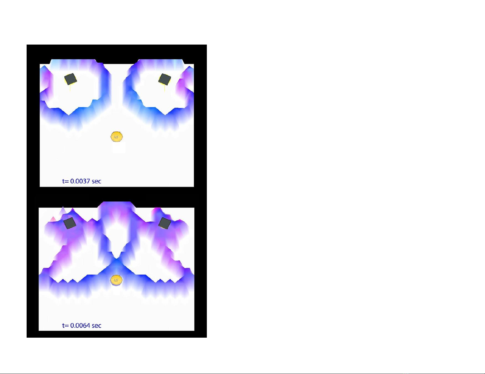
To the left is a 2 dimensional simulation of a 1ms wave pulse
from a pair of conventional speakers into a room similar to the
above. Because the dispersion exceeds 60 degrees,
undesirable energy from each speaker is reflected back into
the room within a few thousandths of a second. This reflected
energy is out of sync with the original signal.
A few milliseconds later, the first wave-front is about to reach
the listener, while the reflected energy is close behind. These
early reflections alter the original tonal balance. As they occur
within the fusion time window, the brain cannot separate the
sounds.
Page 56

After less than 1/100th of a second, the room has
55
developed a complex wave pattern with energy varying
with room position. The listener is now awash in a series of
wave-fronts which will soon reflect off the wall behind.
A mere 5 milliseconds later, the initial direct wave-front
has now reflected off the rear wall and has made its way
back to the listener.
The listener will perceive this reflection as additional bass
energy, though a standing wave has not had time to
develop.
It is a common misconception that such low frequency
excess energy is merely the result of inevitable resonances
within the room, when a large portion can be attributed to
initial reflections.
Page 57
56
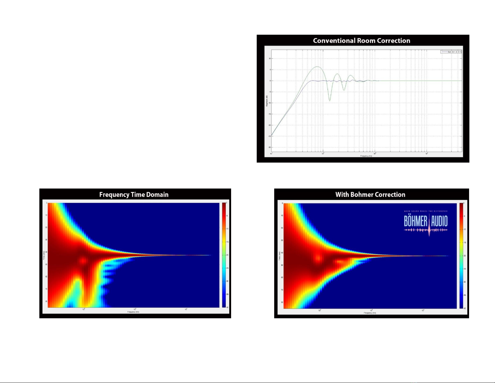
To the right is the irregular frequency response of a
speaker on axis in the presence of room boundaries.
The smoothed curve is the result of applying
conventional room correction methods. Below left is
the impact of the correction on the Fequency-Time
domain. Below right is the same wavelet plot with the
Bohmer correction method.
Page 58
57
CE Declaration of Conformity
Legacy Audio
3023 E. Sangamon Ave.
Springfield, IL 62702 USA
800-283-4644
States that this product is in conformity with the
with the essential requirements and other relevant
provisions of:
Low Voltage Directive 2006/95/EC
EMC Directive 2004/108/EC
WEEE Compliance
Product Disposal—
Certain international, national
and/or local laws and/or
regulations may apply regarding
the disposal of this product. For
further detailed information,
please contact the retailer where
you purchased this product or
the Legacy Audio Distributor in
your country. A listing of Legacy
Audio Distributors can be found
on the Legacy Audio website
www.legacyaudio.com
or by contacting Legacy Audio
at: 3023 E. Sangamon Ave.,
Springfield, IL 62702,
USA—Phone: +1 217 544-3178.
Page 59

58
Notes:
Page 60

59
©2016 Legacy Audio
3023 E Sangamon Ave.
Springfield, IL 62702
Phone: 800-283-4644
Fax: 217-544-1483
 Loading...