

Page 1
MANUFACTURER’S LIMITED TWO YEAR
LEGACY SOUND CORP. warrants this unit to be free from defective material or workmanship and will repair or
replace this unit or any part thereof if it proves defective in normal use or service within two (2) years from
the date of original purchase.
Our obligation under this warranty is limited to repairing or replacing, at our discretion, the defective instrument
or any part thereof when it is returned, transportation prepaid to the Legacy Service Center at the address
below. This warranty will be considered void if the unit has been tampered with, improperly serviced, subjected
to abuse or misuse or if installed in a commercial vehicle. This warranty does not cover accidental damage.
When returning this unit for service, please include $15.00 for return postage and handling. Send your unit to:
IMPORTANT: Pack carefully in original carton if possible. We are not
responsible for damage incurred in returning items for repair. A letter
stating your exact street address, daytime phone number, and the
problem you are experiencing should be included. You must also enclose
a copy of the original receipt as proof of date of purchase.
FOR YOUR PROTECTION
Completely and immediately mail the Product Registration Card
so that we may contact you directly in the event a safety
notification is issued in accordance with the 1972 Consumer
Product Safety Act, or for other reasons Legacy may deem
TECHNICAL SUPPORT HOTLINE
Our technical department will gladly answer any questions
you may have about our products. They cannot, however
tell you the status of a repair, or handle other customer
service situations.
1-800-934-2277
Monday through Thursday, 9AM to 5PM
Friday 9AM to 2PM Eastern.
necessary.
LEGACY SERVICE CENTER
1600 63rd Street
Brooklyn, NY 11204
LA-488
LA-588
LA-688
LA-788
LA-988
LA-1088
LA-1488
LA-1888
LA-2088
LA-2288
LA-2488D
WWW.legacycaraudio.com
Page 2
Congratulations
on your purchase of a new
Legacy American Series amplifier !
Legacy amps are some of the most advanced car amplification products
available. These quality audio products are designed and engineered to afford
you years of uncompromised musical service. Legacy has utilized the latest
electronic technologies in order to deliver a superb listening experience.
This innovative system has been designed utilizing a 12 V DC Negative Ground
power supply. The LEGACY AMERICAN Series amps incorporate two to
eight MOSFETS in the different models.
This design produces enough available voltage to supply the main amplifier
sections, and still have a huge amount of reserve voltage for peak “high
demand” situations.
The Legacy line has been designed to ensure adequate headroom for even
the most demanding peaks and dynamic ranges found on today’s CD’s and
recordings. Used properly, these amplifiers will provide you with years of
listening pleasure.
USER MANUAL
table of contents
SPECIFICATIONS
1~2
LA-488/588/788/988/1488/1888/2088/2288
3
FEATURES & CONTROLS
LA-688/1088 FEATURES & CONTROLS
4
LA-2488D FEATURES & CONTROLS
5
ELECTRICAL WIRING, INSTALLATION & SETUP
6
2 CH STEREO INPUT CONNECTIONS
7
4 CH STEREO INPUT CONNECTIONS
8
BRIDGED INPUT CONNECTIONS
9
BASIC STEREO SPEAKER CONNECTIONS
11
MONO-BRIDGED SPEAKER CONNECTIONS
12
MONO BLOCK INPUT & SPEAKER CONNECTIONS
13
TROUBLESHOOTING
14
Legacy American Amplifier Features
LA-488/588/688/788/988/1088
1488/1888/2088/2288 also feature:
• Soft turn on/off circuit
• Variable gain control
• Remote turn on/off
• Hi/low level inputs
• Power on LED indicator
• LED protection indicator
Specifications
OUTPUT POWER
RMS @ 4 OHMS
RMS @ 2 OHMS
MAX OUTPUT
BRIDGE MODE
FREQUENCY RESPONSE
INPUT IMPEDANCE
LOW LEVEL INPUTS
HIGH LEVEL INPUTS
INPUT SENSITIVITY
LOW LEVEL INPUTS
HIGH LEVEL INPUTS
POWER SUPPLY VOLTAGE
MATCHING SPEAKER IMPEDANCE
STEREO MODE
BRIDGED MODE
MAXIMUM CURRENT DRAW
• Fully adjustable electronic crossover network
• Remote control Bass boost ( 0 – +18dB @ 60Hz )
• 2 ohm stereo stable
• Bridgeable into 4 ohms
• MOSFET PWM power supplies
LA
-
LA
-
488
2CH amplifier
2 X 40W
2 X 60W
2 X 300W
1 X 600W
10Hz-30 kHz
10 k-Ohms
100 Ohms
250 mV
2.5V
14.4 VDC/NEG GD (10.5-16V)
2-4 OHMS
4-8 OHMS
15 A
588
2CH amplifier
2 X 50W
2 X 75W
2 X 400W
1 X 800W
2-4 OHMS
4-8 OHMS
15 A
LA
-
688
4CH amplifier
4 X 35W
4 X 55W
4 X 250W
2 X 250W+500W
OR 2 X 500W
2-4 OHMS
4-8 OHMS
20 A
LA
-
2CH amplifier
2 X 75W
2 X 125W
2 X 500W
1 X 1000W
2-4 OHMS
4-8 OHMS
20 A
788
LA
-
988
2CH amplifier
2 X 100W
2 X 150W
2 X 600W
1 X 1200W
2-4 OHMS
4-8 OHMS
30 A
1
DIMENSIONS, W x H x L, inches
(mm)
NET WEIGHT, LBS (KG)
11.38 X 2.48 X 8.25
(289 X 63 X 209)
4.84(2.2)
11.38 X 2.48 X 9.25
(
289 X 63
5.28(2.4)
X 235)
11.38 X 2.48 X
(
289 X 63
7.15(3.25)
Features and Specifications
12
X 305)
11.38 X 2.48 X
(
289 X 63
6.6(3)
specs
12
X 305)
11.38 X 2.48 X
(
289 X 63
7.59(3.45)
13.5
X 343)
Page 3
Legacy American Amplifier Features
LA-2488D also feature:
· Mono Block Subwoofer Amplifier
· 1 Ohm Stable
· MOSFET Power Supply
· PWM (Pulse-Width-Modulation) System
· Glass Epoxy PCB
· Gold Plated RCA Inputs for Line Input & Bypass Output.
· Gold Plated Terminals for Speaker Output and Power Input.
· Thermal, Overload and Short Protection
· Variable Sub-sonic Filter (15Hz~40Hz, 24dB/Octave)
· Variable Low-pass Filter (20Hz~250Hz, 24dB/Octave)
LA
-
Specifications
OUTPUT POWER
RMS @ 4 OHMS
RMS @ 2 OHMS
MAX OUTPUT
BRIDGE MODE
FREQUENCY RESPONSE
INPUT IMPEDANCE
LOW LEVEL INPUTS
HIGH LEVEL INPUTS
1088
4CH amplifier
4 X 75W
4 X 115W
4 X 500W
2 X 500W+1000W
OR
2 X 1000W
10Hz-30 kHz
10 k-Ohms
100 Ohms
LA
-
1488
2CH amplifier
2 X 125W
2 X 200W
2 X 800W
1 X 1600W
LA
-
1888
2CH amplifier
2 X 150W
2 X 225W
2 X 1000W
1 X 2000W
· Phase Control 0-180 degree
· Remote Bass Control
· Input Impedance : 10K Ohms
· Soft Turn On/Off
· Advanced Protection Circuitry
· S/N Ratio:>90dB
LA
-
2088
2CH amplifier
2 X 200W
2 X 300W
2 X 1200W
1 X 2400W
LA
-
2288
2CH amplifier
2 X 300W
2 X 450
2 X 200
W
0W
1 X 4000W
LA
Mono channel amplifier
200W mono
335W mono
2000W mono
20-250Hz( 3dB)
10 k-Ohms
100 Ohms
-
2488D
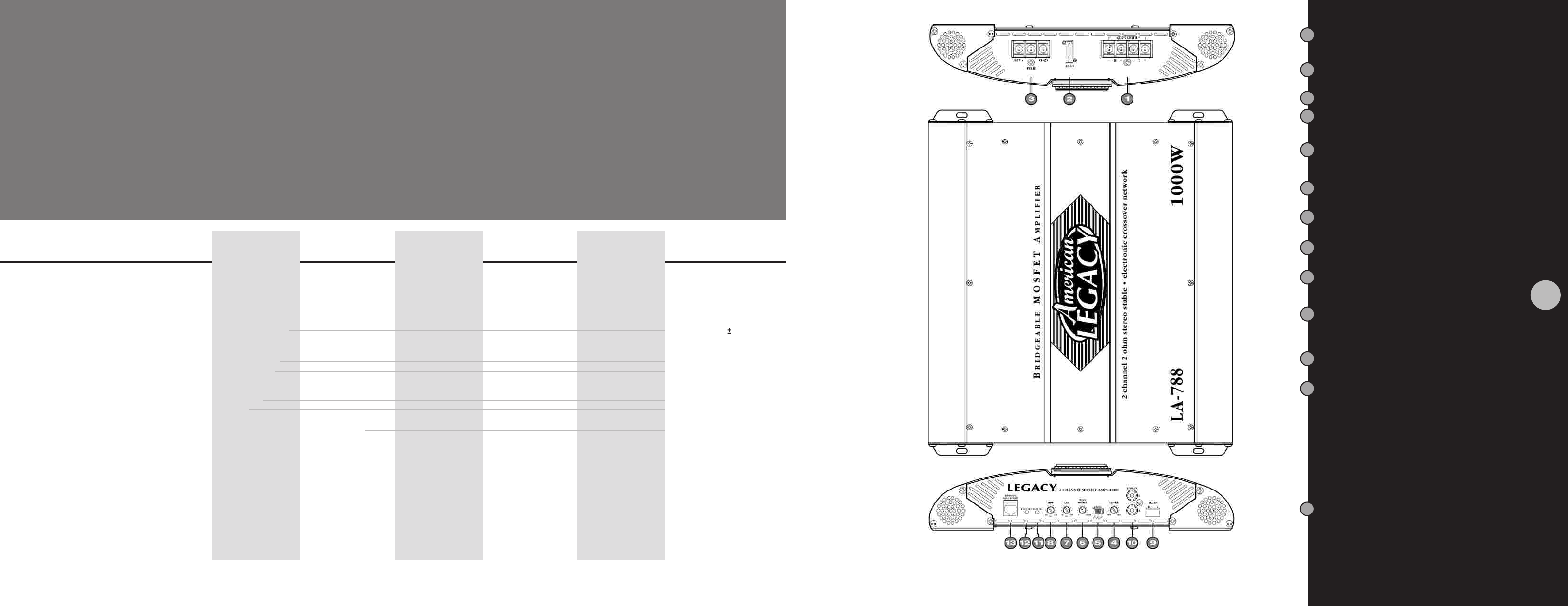
Speaker Terminals1
These terminals are 14K Gold plated for high
conductivity and minimum impedance loss. The
terminals face upwards for easy wiring in tight
situations.
Fuse
2
Protects the amplifier as well as the automobile
electrical system from short circuit conditions.
Power Supply Terminals
3
Input Level Control
4
Use this control to match the output of the head
unit to the amplifier. If distortion is pr esent, reduce
the setting of this control.
5
Crossover Mode Switch
In a full range system, set this to FULL. If the amp
is being used to power a crossover system, set to
either HPF or LPF as needed.
Bass Boost Control
6
Allows you to increase the bass signal level sent
to the speakers
Low Pass Control
7
Permits you to adjust the crossover frequency
from 35 Hz to 400 Hz to suit the subwoofers
High Pass Control
8
Permits you to adjust the crossover frequency
from 80 Hz to 2.5 kHz to suit the tweeters
High Level Input (Low Impedance)
9
Use these if your car stereo does not have
RCA output jacks: connect the speaker output
from the head unit to these inputs
Low Level Input (High Impedance)
10
This unit is provided with gold-plated RCA input
jacks. Using RCA-RCA type patch cords,
connect these inputs to the RCA outputs from
your head unit.
Power LED Indicator
11
This LED is illuminated when the REMOTE ON
system is turned on.
3
INPUT SENSITIVITY
LOW LEVEL INPUTS
HIGH LEVEL INPUTS
POWER SUPPLY VOLTAGE
MATCHING SPEAKER IMPEDANCE
STEREO MODE
BRIDGED MODE
MAXIMUM CURRENT DRAW
DIMENSIONS, W x H x L, inches
(mm)
NET WEIGHT, LBS (KG)
specs
Features and Specifications
250 mV
2.5V
14.4 VDC/NEG GD (10.5-16V)
2-4 OHMS
4-8 OHMS
40 A
11.38 X 2.48 X
(
289 X 63
X 432)
9.59 (4.36)
2-4 OHMS
4-8 OHMS
30 A
17
11.38 X 2.48 X
(
289 X 63
8.36 (3.8)
X 381)
15
2-4 OHMS
4-8 OHMS
40 A
11.38 X 2.48 X
(
289 X 63
17
X 432)
9.46 (4.3)
2-4 OHMS
4-8 OHMS
50 A
11.38 X 2.48 X
(
289 X 63
19
X 482)
10.6 (4.82)
2-4 OHMS
4-8 OHMS
70 A
11.38 X 2.48 X
(
289 X 63
21
X 532)
11.88 (5.4)
250 mV
4V
14.4 VDC/NEG GD
(10.5-16V)
1 OHMS
4 OHMS
40 A
11.38 X 2.48 X
(
289 X 63
13
X 330)
8.14 (3.7)
12
Protection LED Indicator
The protection circuitry in the amp will disable it
if it senses an input overload, speaker short circuit,
or thermal overload conditions. Should this occur,
the PROTECT LED will be illuminated. At that time,
it is important that you check to determine what
has caused the protection circuitry to become
activated.
If the amp shut off because of a thermal overload,
allow it to cool down before attempting to restart.
If the shutdown occured because of an input
overload, or speaker short circuit, be sure to
correct these conditions before attempting to
restart the amp.
T o reset the amp, turn the REMOTE power of f and
on again.
13
Remote Bass Boost
Plug in the Remote Bass Boost Control wire in here.
LA-488/588/788/988/1488/1888/2088/2288
Features and Controls
Page 4
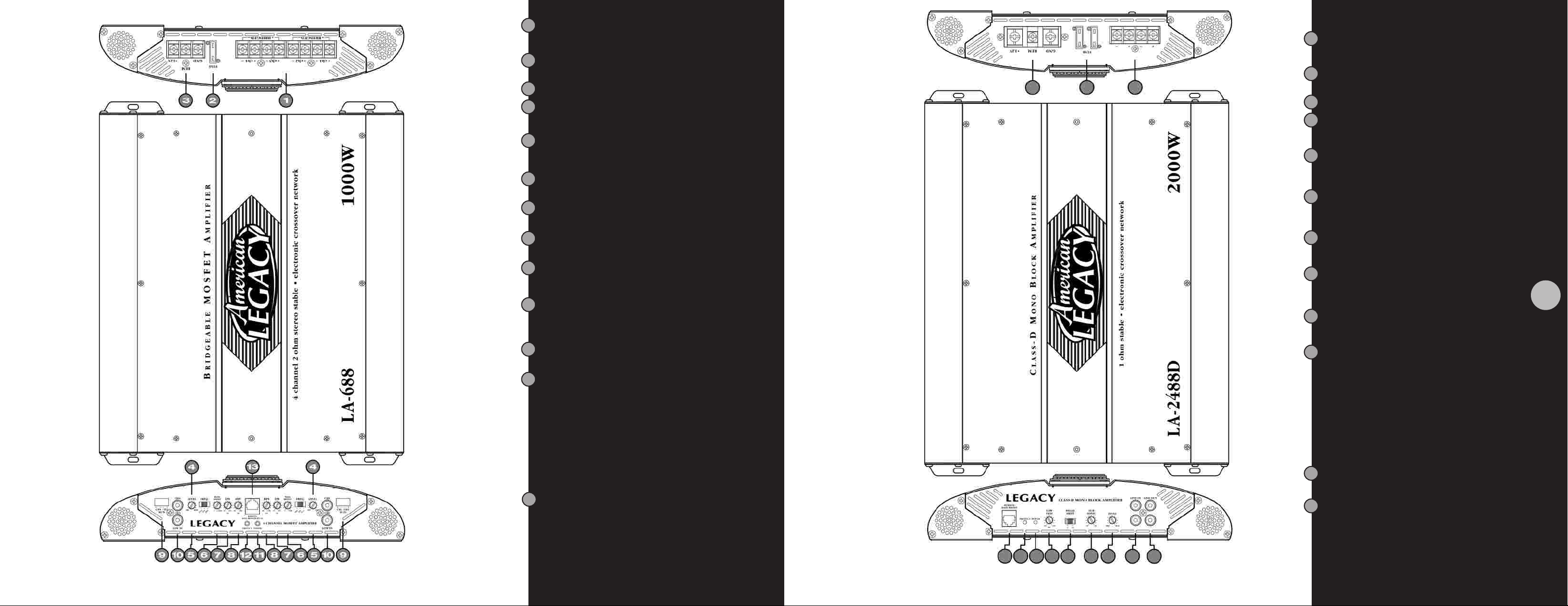
1
Speaker Terminals
These terminals are 14K Gold plated for high
conductivity and minimum impedance loss. The
terminals face upwards for easy wiring in tight
situations.
2
Fuse
Protects the amplifier as well as the automobile
electrical system from short circuit conditions.
Power Supply Terminals
3
Input Level Control
4
Use this control to match the output of the head
unit to the amplifier. If distortion is pr esent, reduce
the setting of this control.
5
Crossover Mode Switch
In a full range system, set this to FULL. If the amp
is being used to power a crossover system, set to
either HPF or LPF as needed.
Bass Boost Control
6
Allows you to increase the bass signal level sent
to the speakers
Low Pass Control
7
Permits you to adjust the crossover frequency
from 35 Hz to 400 Hz to suit the subwoofers
High Pass Control
8
Permits you to adjust the crossover frequency
from 80 Hz to 2.5 kHz to suit the tweeters
High Level Input (Low Impedance)
9
Use these if your car stereo does not have
RCA output jacks: connect the speaker output
from the head unit to these inputs
Low Level Input (High Impedance)
10
This unit is provided with gold-plated RCA input
jacks. Using RCA-RCA type patch cords,
connect these inputs to the RCA outputs from
your head unit.
Power LED Indicator
11
This LED is illuminated when the REMOTE ON
system is turned on.
12
Protection LED Indicator
The protection circuitry in the amp will disable it
if it senses an input overload, speaker short circuit,
or thermal overload conditions. Should this occur,
the PROTECT LED will be illuminated. At that time,
it is important that you check to determine what
has caused the protection circuitry to become
activated.
If the amp shut off because of a thermal overload,
allow it to cool down before attempting to restart.
If the shutdown occured because of an input
overload, or speaker short circuit, be sure to
correct these conditions before attempting to
restart the amp.
T o reset the amp, turn the REMOTE power off and
on again.
1 3
Remote Bass Boost
Plug in the Remote Bass Boost Control wire in here.
1
Speaker Terminals
These terminals are 14K Gold plated for high conductivity
and minimum impedance loss. The terminals face
upwards for easy wiring in tight situations.
Fuse
2
Protects the amplifier as well as the automobile electrical
system from short circuit conditions.
Power Supply Terminals
3
Input Level Control
4
Use this control to match the output of the head unit
to the amplifier. If distortion is present, reduce the
setting of this control.
5
Phase Shift Switch
Allows you to change the phase of your subwoofer
from 0 degree to 180 degrees to help compensate from
timing difference between drivers.
High Pass Subsonic Filter
6
Adjustable from 15Hz to 40Hz with a slope of 24dB per
octave.This allows for the attenuation of frequencies that
are mostly inaudible and cause unnecessary strain on the
amplifier.
Crossover Low Pass Filter
7
Adjustable from 20Hz to 250Hz with a slope of 24dB per
octave.This allows for the adjustment of the upper point
of the frequency bandwidth and the respective subwoofer.
Low Level Input (High Impedance)
8
This unit is provided with gold-plated RCA input
jacks. Using RCA-RCA type patch cords, connect
these inputs to the RCA outputs from your head
unit.
Low Level Output (High Impedance)
9
This unit is provided with gold-plated RCA Output jacks.
Using RCA-RCA type patch cords, connect these Outputs
to the RCA Inputs for your anyther amplifier.
Protection LED Indicator
10
The protection circuitry in the amp will disable it if it
senses an input overload, speaker short circuit, or
thermal overload conditions. Should this occur, the
PROTECT LED will be illuminated. At that time, it is
important that you check to determine what has caused
the protection circuitry to become activated.
If the amp shut off because of a thermal overload,
allow it to cool down before attempting to restart.
If the shutdown occured because of an input overload,
or speaker short circuit, be sure to correct these
conditions before attempting to restart the amp.
To reset the amp, turn the REMOTE power off and on
again.
Power LED Indicator
11
This LED is illuminated when the REMOTE ON
system is turned on.
Remote Dash-mount Gain Control
1212
This amplifier come complete with a compact remote
GAIN CONTROLLER which can be conveniently mounted
on or under the dashboard of your car.
5
LA-688/1088
Features and Controls
LA-2488D
Features and Controls
Page 5
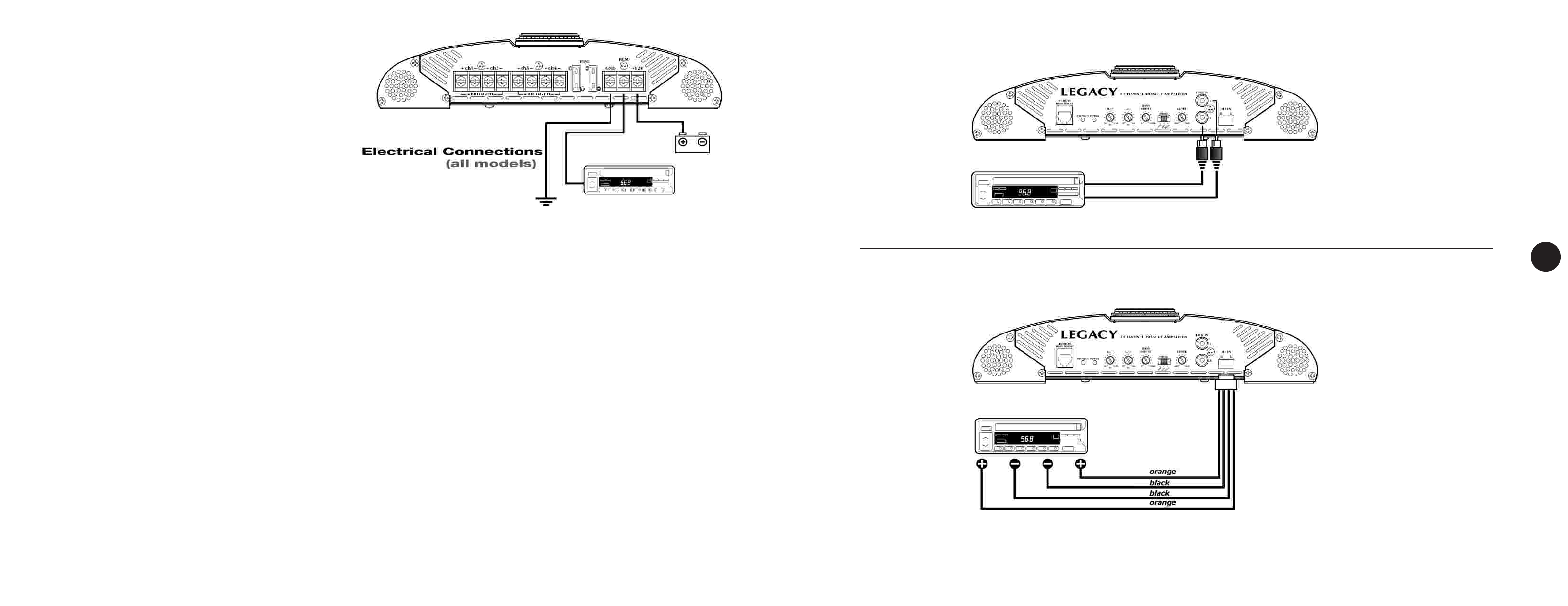
Making Power Connections
1. Connect the +12V terminal directly to the car battery (+) terminal.
2. Connect the GROUND terminal directly to the car battery (-)
terminal OR to a good clean, paint-free chassis ground point.
3. To ensure a good ground, and to prevent “motor-boating” noise
in the system, make an additional connection from the car battery
(-) terminal to the chassis of the stereo unit, using 12 gauge
minimum wire.
4. Connect the REMOTE terminal to an external switch for positive
12V turnon-off. This may be connected to the head unit power
antenna lead.
Installation Precautions
This amplifier comes complete with all mounting harware required. Please remember that this is a high-power unit, which generates considerable
electrical energy and heat. Therefore, be sure to install the unit in a place with sufficient airflow, a minimum of dust, and no moisture. Allow enough
space around the cooling fins to permit reasonable airflow and cooling.
• Before you drill or cut any holes, investigate your car’s layout very carefully. Take care when you work near the gas tank, fuel lines, hydraulic line
and electrical wiring.
• Do not operate the amplifier when it is unmounted. Attach all audio system components securely within the automobile to prevent damage, especially
in an accident.
• Do not mount this amplifier so that the wire connections are unprotected or in a pinched condition, or likely to be damaged by nearby objects. Be
sure to select a location inside your vehicle which has adequate ventilation.
• Before making or breaking power connections in your system, disconnect the vehicle battery. Confirm that your head unit or other equipment is
turned off while connecting the input jacks and speaker terminals.
• If you need to replace the power fuse, only replace it with a fuse identical to that supplied with the system. Using a fuse of a different type or
rating may result in damage to your system which isn’t covered by the manufacturer’s warranty.
Low Level Stereo Input Connection
High Level Stereo Input Connection
PLEASE NOTE! If using high
level inputs, do not use the
low level RCA inputs at the
same time!
LALALALALALALALA-
2CH AMPS
488
588
788
988
1488
1888
2088
2288
7
Setting Up and Turning On Your New Amplifier
After all electrical connections have been made, and physical installation is complete, turn on your stereo and listen for the amplifier to turn on. If
there are any unusual noises from the speakers, turn the stereo off and recheck ALL wiring.
Assuming the amplifier turn on normally, you may have to adjust the LEVEL control(s) to match the output levels from your head unit. Follow these
steps:
1. Set the volume control on your head unit to about the 2/3 position.
2. Adjust the amplifier LEVEL control(s) to an average listening position.
3. Turn the head unit volume all the way down, and listen for background noise.
4. Start your vehicle, and again, listen for background noise.
5. By fine tuning the LEVEL control(s), you can reduce background and engine noise, if present.
These adjustments should only be made once. After that, use the head unit volume control to adjust the system volume, not the LEVEL control(s).
CAUTION: Never turn the LEVEL control(s) up any higher than you need to get clear sound at 2/3 volume on the head unit.
Electrical Wiring and Installation
inputs
Input Connections
Page 6
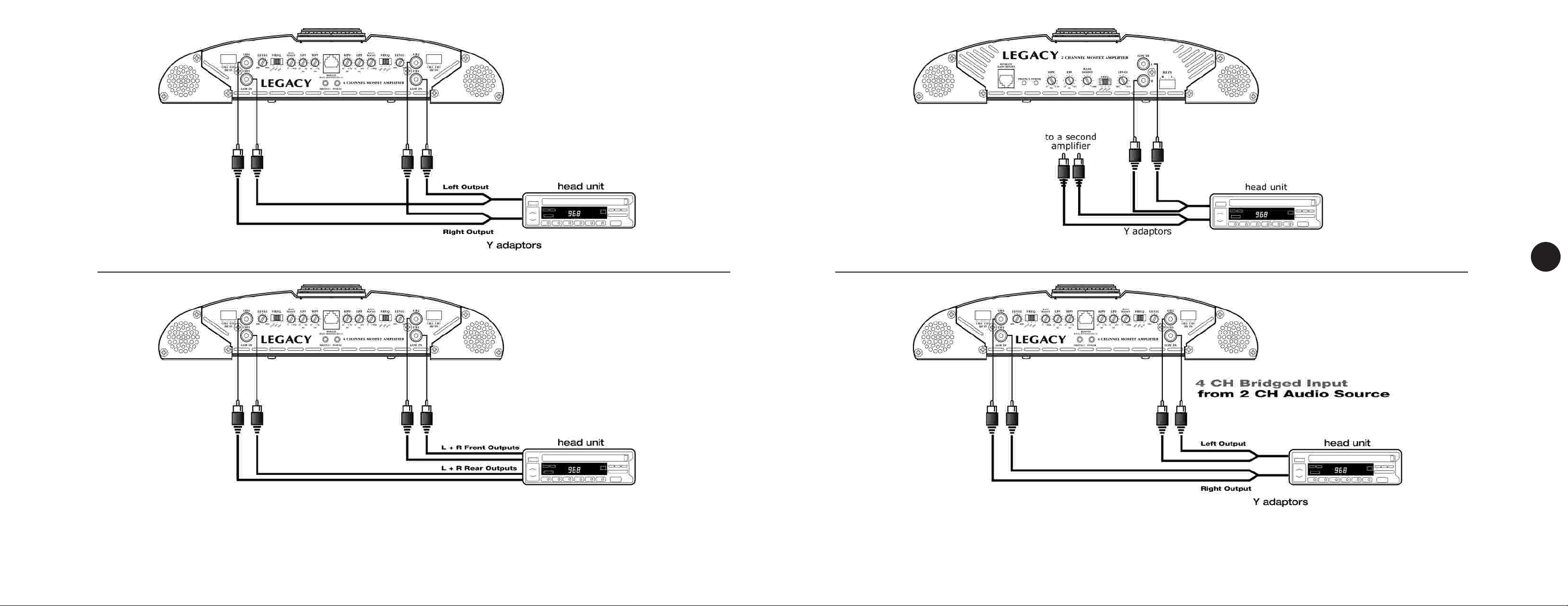
LA-
688
LA-
488
LA-
4CH AMPS
1088
Low Level 4 CH Stereo Input
from 2 CH Audio Source
Bridged Input Connection
LALALALALALALA-
2CH AMPS
LALA-
4CH AMPS
588
788
988
1488
1888
2088
2288
9
688
1088
inputs
Input Connections
Low Level 4 CH Stereo Input
from 4 CH Audio Source
inputs
Input Connections
Page 7
LA-
688
LA-
488
LA-
4CH AMPS
1088
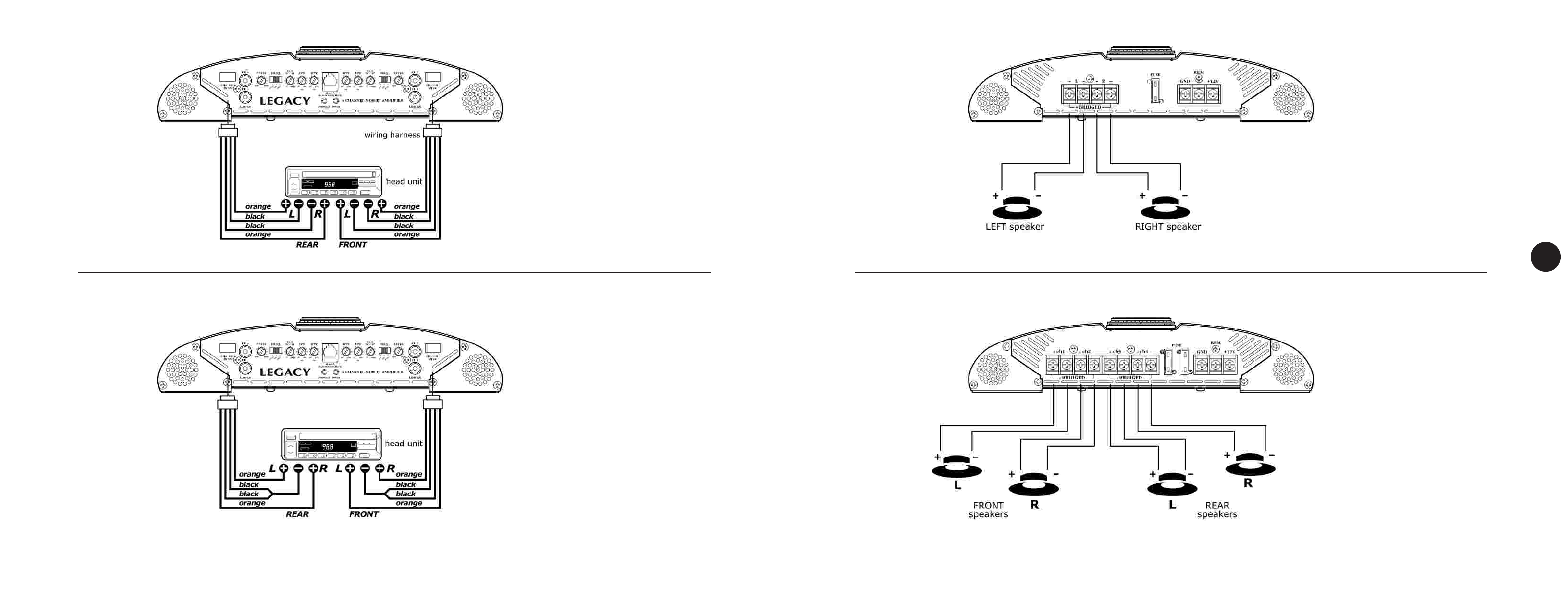
High Level 4 CH Stereo Input
from 4CH Audio Source
floating ground connection
Basic Stereo Output
LALALALALALALA-
2CH AMPS
LALA-
4CH AMPS
588
788
988
1488
1888
2088
2288
11
688
1088
inputs
Input Connections
High Level 4 CH Stereo Input
from 4CH Audio Source
common ground connection
Basic 4CH Output
Speakers
Speaker Connections
Page 8
LALALA-
488
588
788
Low Level Stereo Input Connection
LA-
2488D
MONO CHANNEL
AMPS
LALALALALA-
2CH AMPS
LALA-
4CH AMPS
988
1488
1888
2088
2288
688
1088
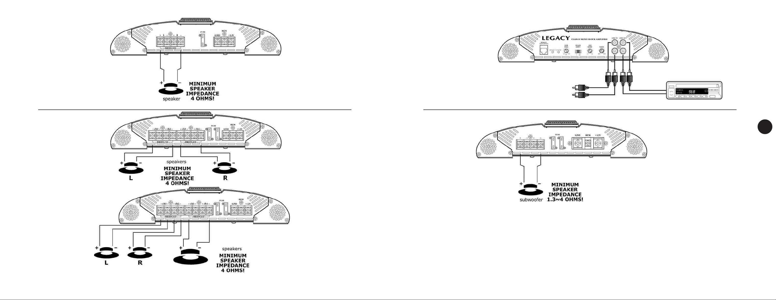
Bridged Mono Output
13
2 CH Mono-Bridged Output
Speaker Output Connection
Speakers
Speaker Connections
2 CH Stereo plus
Mono-Bridged
Subwoofer Output
inputs/Speaker
Input Connections/Speaker Connection
Page 9

Amplifier will not power up.
• Check for good ground connection.
• Check that remote DC terminal has at least +12v DC.
• Check that there is battery power on the + terminal.
• Check all fuses.
• Check that Protection LED is not lit. If it is lit, shut off amplifier
briefly and then repower it.
High hiss or engine noise (alternator whine) in
speakers.
• Disconnect all RCA inputs to the amplifier(s) – if hiss/noise
disappears, then plug in the component driving the amplifier
and unplug its inputs. If hiss/noise disappears, go on until the
faulty/noisy component is found.
• It is best to set the amplifier's input level as insensitive as
possible. The best subjective S/N ratio is obtainable this way .
T ry to drive as high a signal level from the head unit as possible.
Protection LED comes on when the amplifier is
powered up.
• Check for shorts on speaker leads.
• Check that the volume control on the head unit is turned
down low.
• Remove speaker leads, and reset the amplifier. If the
Protection LED still comes on, then the amplifier is faulty.
STOP
4 ohm
2 -c hannel Amplifier
(Operating in Stereo)
YES! NO!
Two 4-ohm speakers, wired in stereo,
will present a 4-ohm load to each
channel of the amplifier. Most twochannel amplifiers will work well in this
configuration.
sound around, Inc.
1600 63rd street. brooklyn. ny 11204
4 ohm
STOP
4 ohm
2 -c hannel Amplifier
(Operating in
Bridged Mono)
4 ohm
Two 4-ohm speakers, wired in parallel
to a bridged two-channel amplifier.
will present a 2-ohm mono load to the
amplifier. MOST TWO-CHANNEL
AMPLIFIERS DO NOT SUPPORT 2-OHM
MONO OPERATION! AMPLIFIER DAMAGE
COULD RESULT!
15
Amplifier(s) gets very hot.
• Check that the minimum speaker impedance for that model
is correct.
• Check for speaker shorts.
• Check that there is good airflow around the amplifier. In
some applications, an external cooling fan may be required.
Distorted sound
• Check that the Level control(s) is set to match the signal
level of the head unit.
• Check that all crossover frequencies are properly set.
• Check for shorts on the speaker leads.
High squeal noise from speakers.
• This is almost always caused by a poorly-grounded RCA
patch cord.
troubleshooting
4 ohm
4 -c hannel Amplifier
(Operating in Stereo)
YES!
Four 4-ohm speakers, wired in stereo,
will present a 4-ohm load to each
channel of the amplifier. Most fourchannel amplifiers will work well in this
configuration.
4 ohm
4 ohm
4 ohm
4 -c hannel Amplifier
(Operating in
Bridged Mono)
NO!
Four 4-ohm speakers, wired in parallel
to a bridged four-channel amplifier,
will present a 4-ohm mono load to the
amplifier. MOST FOUR-CHANNEL
AMPLIFIERS DO NOT SUPPORT 2-OHM
MONO OPERATION! AMPLIFIER DAMAGE
COULD RESULT!
Troubleshooting
4 ohm
4 ohm
4 ohm
4 ohm
 Loading...