

Page 1
Power MAX (2 Ohms)
Power RMS (4 Ohms)
S/N Ratio
Low Pass Crossover (Variable)
Bass Boost (Variable)
Inputs
Frequency Response
THD (at RMS output)
Channel separation
Damping Factor
Fuse Values
Dimensions
MODELS LA-1800D-BK
1800W x 1
900W x 1
102 dB
50Hz - 150Hz
0 - 18dB
Low Level and Speaker Level Inputs ..............
50Hz - 150Hz
0.01%
90dB
180+
30A x 2
Phase control (Variable) 0 - 180
LA3000D-BK
3000W x 1
1500W x 1
102 dB
50Hz - 150Hz
0 - 18dB
50Hz - 150Hz
0.01%
90dB
180+
30A x 2
0 - 180
LA1800D-SL LA3000D-SL
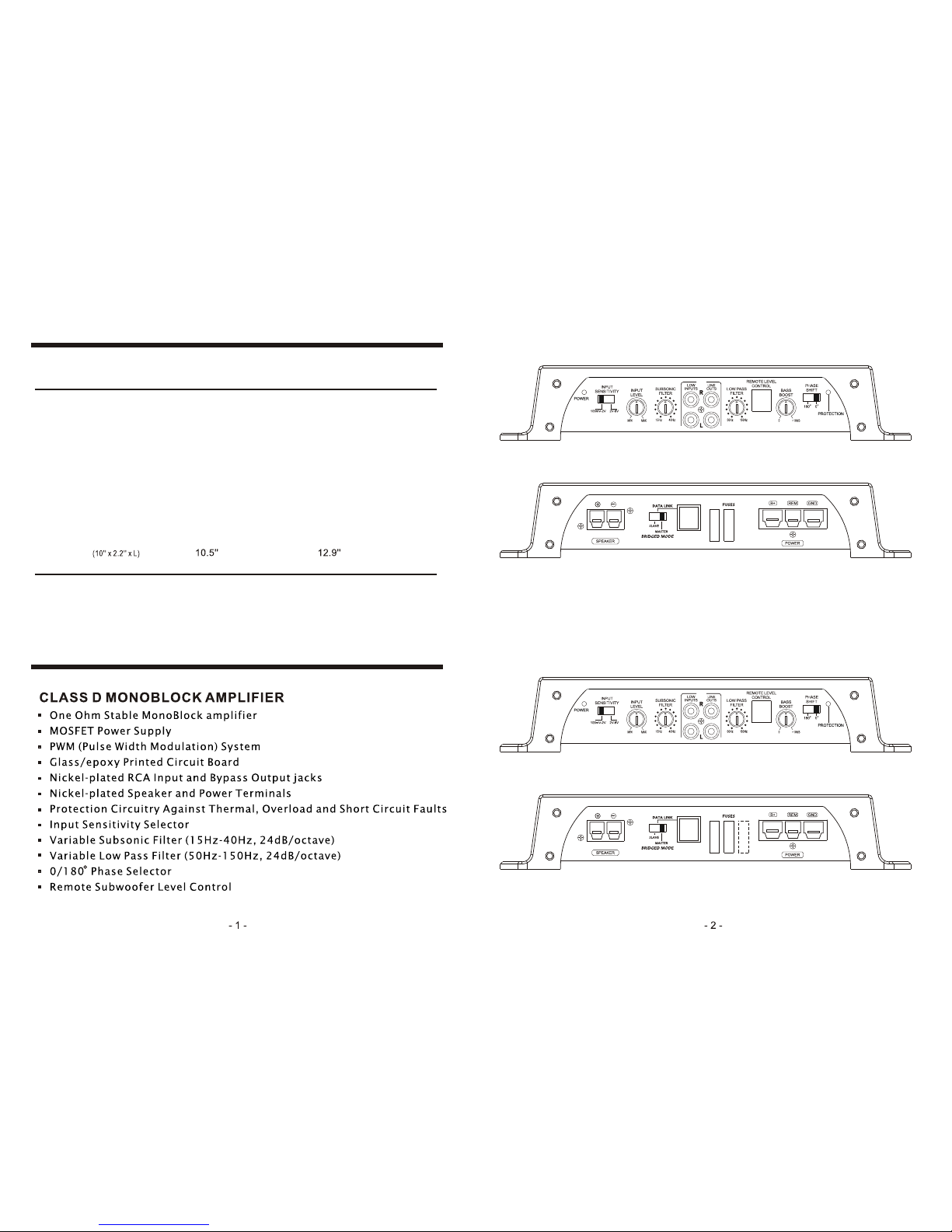
LA1800D-SL / LA1800D-BK
FRONT
REAR
LA3000D-SL / LA3000D-BK
FRONT
REAR
SPECIFICATIONS
FEATURES
Page 2
Installation
Important Installation Considerations and Precautions
1
2
3
4
5
6
7
8
9
10
The design philosophy of this amplifier requires strict adherence to proper installation and load impedance instructions. The minimum recommended impedance
is 2 Ohms.
The fuse rating for the LA1800D-SL and LA1800D-BK Are 60 amperes (3 x 20A
fuses). And the fuse rating for the LA3000D-SL and LA3000D-BK Are 90 ampleres
(3 x 20A fuses). Although sufficient for normal working conditions, overloading
of the amplifier may cause these fuses to blow. Please try to avoid overloading
the amp in this manner.
Take extreme caution when mounting the amplifier, so as not to damage the
chassis with a drill or screwdriver.
Run a 4 gauge wire (as short as possible) to the closest chassis ground point.
Be sure to remove the paint at the connection to the chassis of the vehicle for a
good electrical connection.
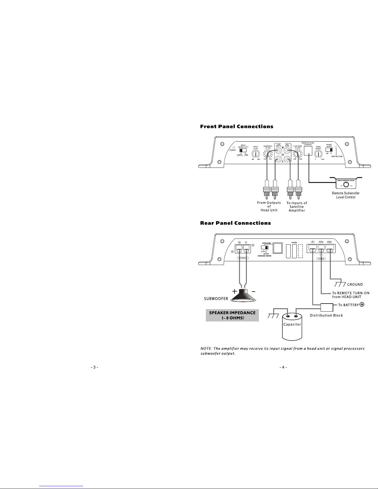
Using RCA interconnect cables, connect all line inputs and outputs per the
wiring diagrams which follow if possible, keep the RCA cords away from the
12V power and Ground wiring.
Mount the amplifier so that air flow is not restricted.
Mount the amplifier to a solid surface, as these amplifiers are extremely heavy.
Place the fuse holder near the amplifier on the 12V POSITIVE lead.
Run a 16 gauge (or larger) wire to the remote turn-on lead of the head unit.
Connect the speaker(s) as per the wiring diagrams in this manual.
Set the controls as described in the following sections of this manual.
Run a 4 gauge wire from the battery, using a fuse within 18 (457mm) of the
positive battery terminal. The purpose of this fuse is to protect the battery in
the event that this wire accidentally contacts the chassis ground on its run to
the amplifier.
,,
While these amplifiers are designed to operate with a minimum load of 1 Ohm, it
is highly recommended that you design your system to operate with 2 Ohms
minimum impedance. Operating a CHAOS digital amp with a speaker impedance
load of under 1 Ohm may result in poor sound quality and serious damage to the
amplifier circuitry. Damage to your amplifier caused by operating with a load of
less than 1 Ohm is not covered under the warranty for this product.
Page 3
Electrical Wiring
The LA1800D-SL(BK) and LA3000D-SL-(BK) are equipped with easy top access screw
terminals. These terminals are nickel-plated in order to ensure excellent electrical contact
and to resist corrosion.
When making electrical connections to the amplifier, please observe the following:
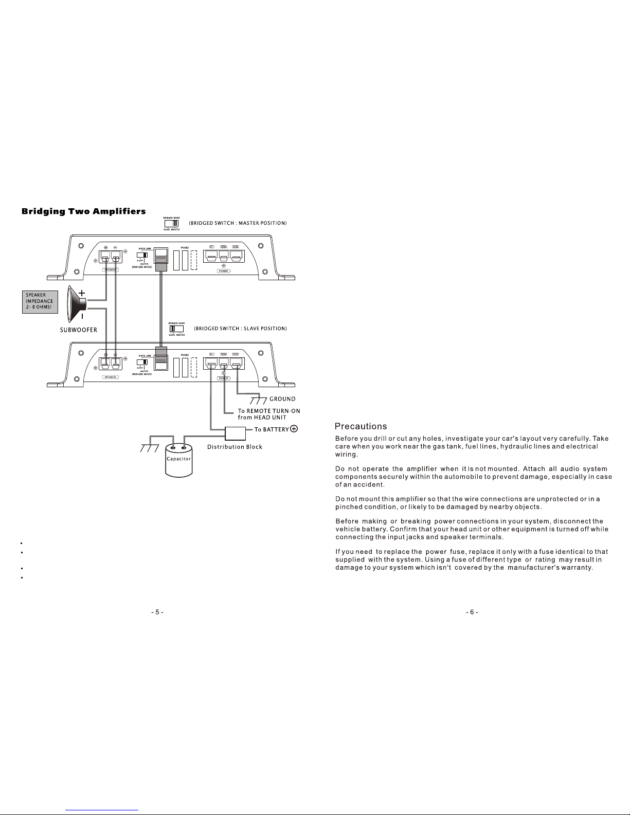
Use at least 8 gauge or heavier wire for power and ground connections.
Wire the amplifier directly to the car battery. Make sure there is circuit protection
(Such as a fuse) on the positive power lead, within 18 inches of the battery.
For the ground connection, use the shortest possible wire to a good chassis ground point.
Wire the Remote connection to the remote turn-on lead of your equalizer or head unit.
In some cases this may be the power antenna lead of the head unit.
Remote Subwoofer Level Control
The LA1800D-SL(BK) And LA3000D-SL(BK) are equipped with a dashboard mount remote
subwoofer level control. Run the supplied dashboard remote control from the front panel of
your amplifier. By turning the level knob clockwise, you will increase the output of low
frequencies.
Fuses
Fuses protect both the amplifier and the electrical system of your vehicle from faulty
conditions. If you must replace the fuse in your amplifier, use a fuse of exactly the same
type and rating. A different type or rating may result in damage or cause a fire.
Mounting the Amplifier
Mark the location for the mounting screw holes by positioning the amplifier where you
wish to install it and use a scribe (or one of the mounting screws) inserted in each
mounting hole to mark the mounting surface. If the mounting surface is carpeted,
measure the hole centers and mark with a felt tip pen.
Drill pilot holes in the mounting surface for the mounting screws and insert the
mounting screws into these holes. Tighten them securely.
Note: Before beginning your installation, be sure to take note of any wires, lines or
other devices in your vehicle which may be located behind any mounting surface.
 Loading...