


Legacy L8305, L8305-EU, L8306, L8306-EU, L8310 Parts and Technical Service Guide
...
Please read and follow instructions
carefully; otherwise, warranty may be void.
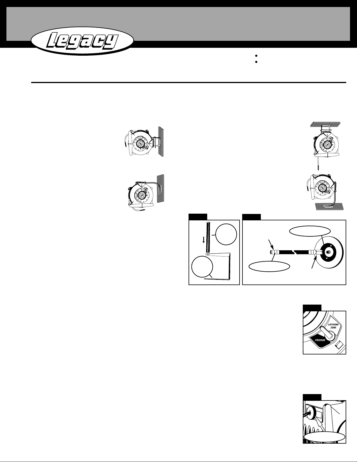
Mounting Options:
CAUTION:
Maximum installation height is 15 ft. (4.5 meters) above ground. Maximum weight of hose end tools is 4 lb. ( 2 kg). Maximum working
pressure is 350 PSI. Do not stand or step on top of reel!
Installation:
LEVELWIND retractable hose reels are designed for minimum assembly.
1) Place bracket on a flat mounting surface. With a pencil trace bracket
back holes onto surface. Use a leveling device to ensure that the
bracket will be level once fastened. Fasten brackets to surface with
screws ( screws are not included ).
2) Remove Bracket Rod (A) from Bracket (B) ( SEE FIGURE 1 )
3) Place reel into bracket making sure the reel hole is aligned with
bracket end holes.
4) Insert Bracket Rod through the aligned holes of Reel and Bracket.
5) Connect female end of lead-in hose to inlet connection on reel.
Connect male end to air or water source ( SEE FIGURE 2 ).
Operating Instructions:
LEVELWIND retractable hose reels can operate in FREERUN or can be latched every 3 ft. by switching to the LATCHING ZONE. Simply turn the mode
switch to desired position! ( SEE FIGURE 3 )
THE “LA TCHING ZONE”: LEVELWIND reels have a single latching zone. The reel can be latched for every drum revolution
approx. 3 feet of hose). There are audible clicking sounds as the spring loaded latch passes over the latching zone. The latching
zone flips the latch so that the latch goes into or by-passes the latching position. Pulling hose straight out off the reel “flips the
latch” so it can go into the latching position. Retracting the hose into the reel keeps the latch “flipped” so that the latch bypasses the latching position.
FREERUN MODE: The hose does not latch in this mode. Hose will automatically retract back into reel. The Hose stopper
position may be adjusted to desired length for application (SEE FIGURE 4)
CAUTION!
Do not release the end of the hose
when rewinding as personal injury or damage could result!
TM
Retractable Air & Water Hose Reels
Parts and Technical Service Guide
Carretes retráctiles para mangueras de aire y de agua guía de componentes y servicio técnico
Dévidoirs de tuyau d'air et d'eau rétractable guide de pièces et de service technique
LLeevveellwwiinndd
TTMM
SSeerriieess
Model L8305 Model L8305-EU Model L8306 Model L8306-EU Model L8310 Model L8310-EU
Model L8335 Model L8335-EU Model L8346 Model L8347 Model L8349
INS8306-0103
MMoouunnttiinngg oovveerrhheeaadd
Up to 15 ft. (4.5 m) from floor. Use
standard Replacement Part L8300-W Wall /
overhead bracket.
MMoouunnttiinngg ttoo wwaallll
Positioned up to 5 ft. (1.8 m) high.
Use standard Replacement Part
L8300-W Wall /Overhead bracket
MMoouunnttiinngg ttoo aa bbeenncchh
Use optional Bench / High Wall mounting
bracket model L8300-B
HHiigghh WWaallll MMoouunnttiinngg
Mount reel between 10 ft. and 15 ft.
high on wall. Use optional Bench / High
Wall mounting bracket Model L8300-B
Fig. 1
Male end to source
Female end to reel inlet
Fig. 2
Reel Inlet
Lead-in Hose
A
Bracket
Rod
B
Bracket
Page 1
LATCHING - Pull out the desired length of hose. As you are pulling out hose from the reel, listen for a “click”. STOP!
Don’t pull any further! If you keep pulling out hose (more than 14”) after hearing the “click”, you will have pulled past the
latching zone. Now, allow the hose to go back into the reel (less than 14”) and the latch will drop into the latching position. The reel is now
latched!
RETRACTING - Assuming the latch is engaged in the latching position, pull out hose until you hear a “click” (approx. 14”). STOP! Don’t
pull any further! If you pull out more than 3 ft. of hose after hearing the “ click”, you will have gone a full drum revolution and back into the
latching zone where the reel will once again be latched. Now, allow the hose to retract back into the reel. The hose reel will continue retracting
hose until it is fully retracted. If you decide to re-latch the reel while you are still retracting hose, simply listen for a click.
STOP! Slowly pull out hose until you hear a second click. STOP! Don’t pull any further. Now, slowly allow the hose back
into the reel (less than 14”) and the latch will drop into the latching position. The reel is now latched.
Fig. 4
Fig. 3
Hose Stopper
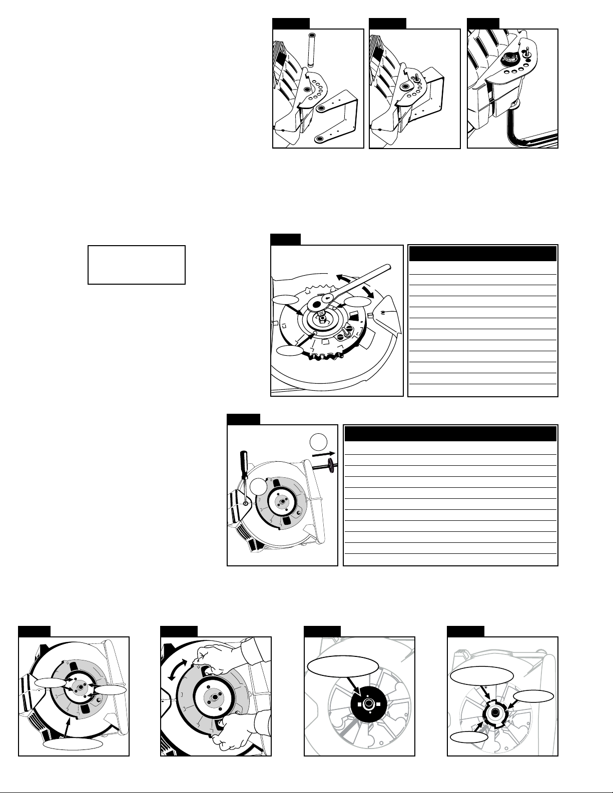
SEVEN POSITION LOCKING BRACE
LEVELWIND retractable hose reels can swing freely on bracket or can
be locked in one of seven positions, allowing for specific mounting
requirements.
SSttaannddaarrdd bbrraacckkeett
1) Remove bracket rod from reel. (SEE FIGURE 5A)
2) Place seven position locking brace over bracket so that bracket
rod holes are aligned. Replace bracket rod so that brace, reel &
bracket are attached. (SEE FIGURE 5B)
3) Rotate bracket so that it is at desired angle & lock into place with
fastener. (SEE FIGURE 5B)
Maintenance Procedures
TENSION ADJUSTMENT:
This reel is preloaded with spring tension that is set at the factory. If the reel becomes completely un-tensioned, please identify your hose reel model
number referenced in the Factory Preset Tensioning Table to find out how many turns are needed for proper tensioning. If a heavy air tool is attached
to the end of the hose, you may need to add tension to overcome the weight of this tool. DO NOT EXCEED one full turn past the number of turns
listed in the Factory Preset Tensioning Chart below.
1) Lay reel on its side. ( SEE FIGURE 7 )
2) Place wrench on hub fitting plate nut. HOLD WRENCH FIRMLY.
3) Unscrew hub. DO NOT REMOVE SIDEPLATE.
4) Turn wrench either ½ turn or no more than one full turn. Turn
clock wise to increase tension. Turn counterclockwise to
decrease tension.
5) Replace hub plate screws and tighten. Return reel to mounting
bracket.
HOSE REPLACEMENT:
To ensure proper performance, please consult the Hose
Replacement Kit table for the appropriate part number
to order. Call 1(800) 645-8258 to order kit.
RReeppllaacceemmeenntt HHoossee KKiittss
1) Pull entire length of hose out of reel.
( SEE FIGURE 8 )
2) While entire length of hose is out of the reel, place
long screw driver ( 3/8” in diameter ) all the way
though the the hole located at the back portion of
reel. This eliminates any chance for the reel to
retract while replacing hose.
SSiiddeeppllaattee rreemmoovvaall
3) Locate inlet sideplate. Remove four fasteners (SEE FIGURE 9 ). While placing fingers on grooves located on the top and bottom of sideplate,
depress locking tabs at the same time with thumbs (SEE FIGURE 10). Rotate side plate either way until sideplate unlocks. Remove sideplate.
4) Remove wear plate (SEE FIGURE 11). Unscrew two fasteners on wear ring and remove wear ring (SEE FIGURE 12).
Page 2
Factory Preset Tensioning Table
MMooddeell ## ## ooff TTuurrnnss
L8305 3
L8305-EU 3
L8306 5
L8306-EU 5
L8310 4
L8310-EU 4
L8335 4
L8335-EU 4
L8346 4
L8347 4
L8349 4
Replacement Hose Kits
MMooddeell ## DDeessccrriippttiioonn
RP005005 Replacement Hose Assembly for L8305
RP005005-EU Replacement Hose Assembly for L8305-EU
RP005006 Replacement Hose Assembly for L8306
RP005006-EU Replacement Hose Assembly for L8306-EU
RP005008 Replacement Hose Assembly for L8310
RP0050058-EU Replacement Hose Assembly for L8310-EU
RP005035 Replacement Hose Assembly for L8335
RP005035-EU Replacement Hose Assembly for L8335-EU
RP005047 Replacement Hose Assembly for L8347
RP005049 Replacement Hose Assembly for L8349, L8346
TOOLS REQUIRED:
Phillips Screw Driver
¾” Socket Wrench
Fig. 5a
Fig. 5b
Fig. 6
Fig.7
Fig. 8
Fig. 9
Fig. 10
Fig. 11
Fig. 12
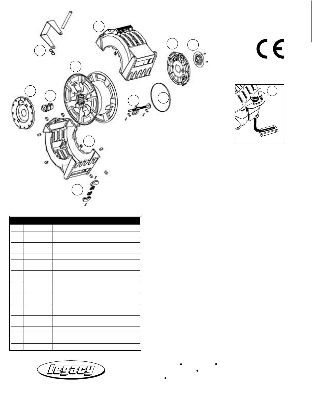
Optional Bench/High Wall
Mounting Bracket
(see figure 6)
Hub
Screw
Decrease
Increase
Screw
2
1
Screws
Back
Inlet Side Plate
Screws
Front
Wear Plate
Wear Ring
Screws
Screws
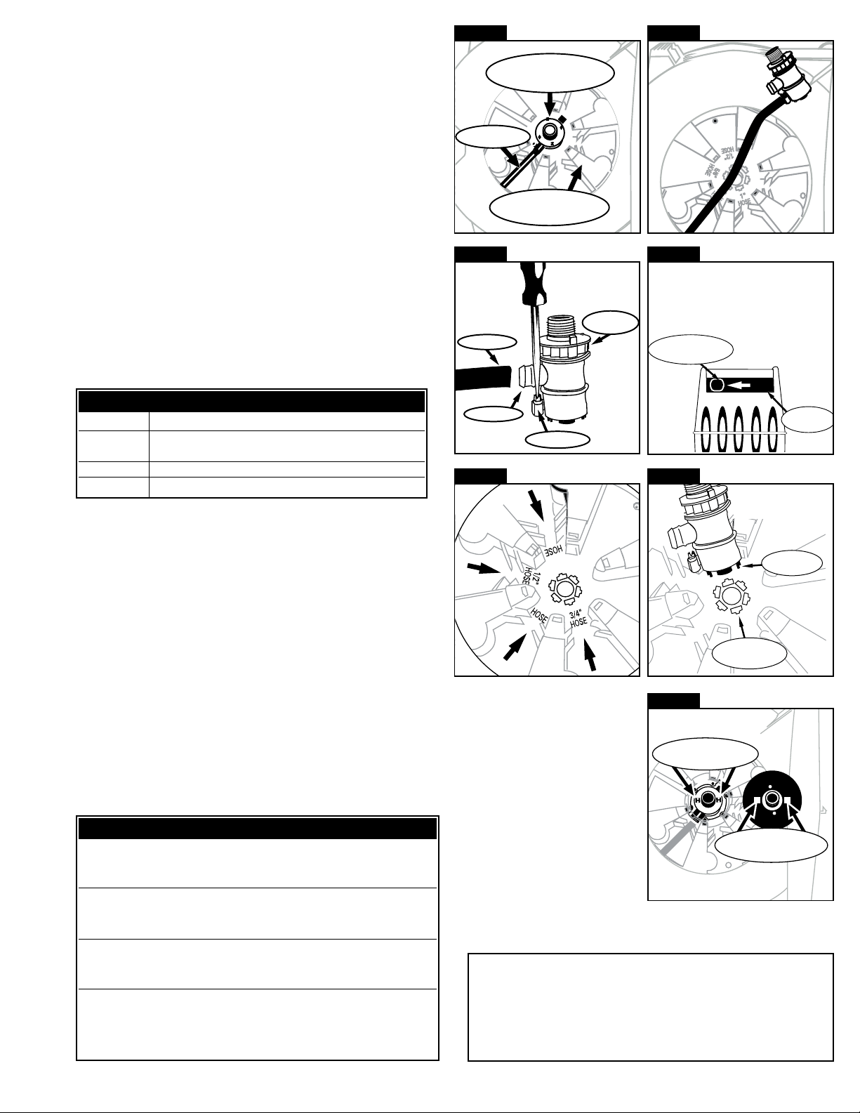
5) Pull swivel assembly firmly from hose spool
( SEE FIGURE 13 and 14 ).
6) Unscrew Hose Clamp and pull hose off hose barb on swivel.
(SEE FIGURE 15)
7) Pull remaining length of hose out reel opening located at the reel
front.
8) Take replacement hose through opening located at the front of reel.
Thread hose through hose leveling mechanism. (SEE FIGURE 16)
9) Insert hose through the center of the hose spool. Four openings are
referenced with the following hose I.D. dimensions located at the
center of hose spool: 3/8”, 1/2”,5/8” & 3/4”. Locate the appropriate
hose I.D. and pull through that opening. (SEE FIGURE 17) Pull
enough hose to allow the hose to connect to appropriate hose barb
on swivel.
10)Replace hose onto hose barb, tighten hose clamp onto hose & place
swivel into hose spool housing. Make sure that drive tabs for spool
located on swivel are accepted by tab receivers in hose spool. (SEE
FIGURE 18)
11)Replace wear ring and fasten with wear ring screws. Replace wear
plate so that the swivel drive tabs insert into wear plate tab receivers.
(SEE FIGURE 19)
12)Replace sideplate so that the plate snaps flush to side of reel. Turn
sideplate until locking tabs connect to sideplate.
13)Turn swivel so that fastener holes of swivel and sideplate align.
Replace the four sideplate fasteners and tighten.
14)Remove Screw driver.
15)Retract hose back into reel.
SWIVEL SEAL REPLACEMENT
IMPORTANT:
To ensure proper performance, please refer to the Swivel
Seal Replacement Kit table to order the correct part number. Call 1(800)
645-8258 to order kit.
1) Repeat steps 1- 6 in the HOSE REPLACEMENT procedure.
2) Place hose onto hose barb of new swivel body. Tighten hose clamp
onto hose & place swivel into hose spool housing. Make sure that
drive tabs for spool located on swivel are accepted by tab receivers in
hose spool (SEE FIGURE 18).
3) Replace wear ring and fasten with wear ring screws. Replace wear
plate so that the swivel drive tabs insert into wear plate tab receivers.
(SEE FIGURE 19)
4) Replace sideplate so that the plate snaps flush to side of reel. Turn
sideplate until locking tabs connect to sideplate.
5) Turn swivel so that fastener holes of swivel and sideplate align.
Replace the four sideplate fasteners and tighten.
6) Remove Screw driver.
7) Retract hose back into reel.
Page 3
TECHNICAL ASSISTANCE:
Call 800-645-8258 if you have any questions
regarding the installation or operation of this
reel.
Fig. 13
Fig. 14
Fig. 15
Fig. 16
Fig. 17
Fig. 18
Fig. 19
Troubleshooting
11)) HHOOSSEE WWIILLLL NNOOTT RREETTRRAACCTT
1a. Pull on hose, push latching switch to FreeRun mode. Retract hose into reel.
1b. Spring is broken. Call service center.
22)) HHOOSSEE WWIILLLL NNOOTT FFUULLLLYY RREETTRRAACCTT
2a. Spring tension too light?
2b. Replacement hose too heavy?
33)) RREEEELL WWIILLLL NNOOTT LLAATTCCHH
3a. Are you releasing hose too quickly?
3b. Broken latching pawl or mode switch?
44)) RREEEELL LLEEAAKKSS
4a. Damaged hose?
4b. Loose fittings?
4c. Worn swivel seals?
Swivel Seal Kits
PPaarrtt ## DDeessccrriippttiioonn
RP005007-38 Seal Replacement kit for reel model L8305, L8305-EU, L8306
L8306-EU, L8310. L8310-EU
RP005007-12 Seal Replacement kit for reel model L8335, L8335-EU
RP005007-58 Seal Replacement kit for reel model L8346, L8347 & L8349
Swivel Body
Hose
Hose Spool
Hose
Swivel
Assembly
Hose Leveling
Mechanism
Hose Barb
Hose Clamp
3/8"
5/8"
Drive Tabs
Tab Receivers
Swivel
Drive T abs
Hose Spool
Reel
Opening
Swivel
Wear Plate
Tab Receivers
LLeeggaaccyy MMaannuuffaaccttuurriinngg CCoommppaannyy
510 57th st. Marion, IA 52302 USA
Tel (319) 373-7305 (800)645-8258 Fax (319) 373-7309
legacy@legacymfg.com www.legacymfg.com
Optional Bench &
High Wall Mounting
Bracket Model L8300-B
Page 4
2
TTWWOO YYEEAARR LLIIMMIITTEEDD WWAARRRRAANNTTYY**
LEGACY MANUFACTURING COMPANY ("LEGACY") warrants that this equipment will be free
from defects in material and workmanship for a period of two (2) year from the date of
purchase, under normal use. LEGACY’S sole obligation under this warranty is limited to
replacing or repairing, free of charge, any equipment that proves to be defective under normal
conditions and use according to the recommendations of LEGACY. To obtain repair or
replacement, the equipment must be shipped to a LEGACY authorized Warranty and Service
Center during the warranty period, transportation charges prepaid, with proof of date of
purchase. In the event of repair or replacement, the warranty period shall not be extended
beyond the original warranty period.
This warranty is extended to the original purchaser only and is not transferable. This warranty
does not apply to normal wear items such as packings, seals, tips and filters, or to equipment
damaged from accident, overload, abuse, misuse, negligence, faulty installation or abrasive or
corrosive materials, or to equipment repaired or altered by anyone not authorized by LEGACY
to repair and alter equipment. No allowance will be granted for any repairs or alterations made
by a purchaser without LEGACY’S prior written consent.
LEGACY WILL BEAR NO OTHER EXPENSE, INCLUDING BUT NOT LIMITED TO LABOR AND
MATERIAL COSTS (OTHER THAN THOSE SPECIFIED HEREIN) OF ANY KIND, AND YOUR
EXCLUSIVE REMEDY, IN LIEU OF ALL INCIDENTAL, SPECIAL, CONSEQUENTIAL OR ANY
OTHER DAMAGES, INCLUDING, BUT NOT LIMITED TO, DAMAGES FOR NEGLIGENCE, IS
LIMITED TO REPAIR OR REPLACEMENT AS HERETOFORE DESCRIBED. THE FOREGOING
WARRANTIES ARE IN LIEU OF ALL OTHER REPRESENTATIONS OR WARRANTIES, EXPRESS
OR IMPLIED OF ANY KIND REGARDING ANY EQUIPMENT, INCLUDING BUT NOT LIMITED TO
THE IMPLIED WARRANTIES OF MERCHANTABILITY AND FITNESS FOR A PARTICULAR
PURPOSE OR USE. IN NO CASE SHALL LEGACY BE LIABLE FOR ANY SPECIAL, INCIDENTAL
OR CONSEQUENTIAL DAMAGES BASED UPON BREACH OF WARRANTY, BREACH OF
CONTRACT, NEGLIGENCE, STRICT LIABILITY, OR ANY OTHER LEGAL THEORY.
Unless modified in a writing, signed by both parties, this Limited Warranty is understood to be
the complete and exclusive agreement between the parties, superseding all prior agreements,
oral or written, and all other communications between the parties relating to the subject
matter of this Limited Warranty. Any action for breach of warranty must be commenced
within twelve (12) months following the end of the warranty period.
* If this equipment contains a hose, the hose is warranted for ninety (90) days only. The
remaining portions of this equipment are warranted for two (2) year, as described above.
While necessary maintenance or repairs on your Legacy equipment can be performed by any
company, we recommend that you use only authorized Legacy service centers. Improper or
incorrectly performed maintenance or repair voids this warranty. Contact us at
legacy@legacymfg.com or www.legacymfg.com for ordering, installation instructions. or a list
of authorized service centers.
Repair Parts
RReeff.. ## RReeppaaiirr PPaarrtt DDeessccrriippttiioonn
1 L8300-W Bracket for wall or overhead ceiling mounting
1a L8300-B Bracket for high wall, bench or floor mounting
2 RP005000BK Outer Top Case w/Trim Ring Black
3 RP005002BK Swivel Plate Side Assembly Black
4 RP005007-38 Swivel Body Assembly 3/8" hose
4 RP005007-12 Swivel Body Assembly 1/2" hose
4 RP005007-58 Swivel Body Assembly 5/8" hose
5 RP005015 Drum Assembly for 50' hose
5 RP005016 Drum Assembly for 75' hose
6 RP005010-14 Layering Device Assembly for Model L8335
L8335-EU, L8346, L8347 & L8349
6 RP005010-20 Layering Device Assembly for Model L8305
L8305-EU, L8306, L8306-EU, L8310, L8310-EU
7 RP005012-137 Drive Belt for Model L8335, L8335-EU
L8346, L8347 & L8349
7 RP005012-140 Drive Belt for Model L8305, L8305-EU, L8306,
L8306-EU, L8310, L8310-EU
8 RP005004BK Latch Plate Side Assembly Black
9 RP005003 Tension Cover
10 RP005001BK Outer Bottom Case Black
11 RP005011 Hose Stopper
8
9
1
5
3
4
6
7
1a
10
11
TM