


Legacy
PAOGAArvlfV1ABL
E
~
~
USER'S MANUAL
X
C:ONTRClLLEA

We
congratulate
you on
vour
purchase
af
DMX
2012
.
Before
pro
ceeding
of
the
use
ofthis p' oduct it
should
be
neces
sary
ta r
ead
care f
ullythefollow
ing
user'sman
ual
t I
install
it
correc
t1y
and
to
make
the
mostof
i
ts
potenti
aliti
es.
Se
ts
ofthe equipment
1.1 Description of me
front
panel
1.2 Unpacking of the eq
uoment
1.3 Acesseries issued with the equipmen and relative documentatien
Description of
the
resrpanel aOOin
stal
.
~tio
n
2.1 Description of the reer- panel
2.2 DMX 5
12
output connection
2.3 Input connection for
oow
e- supply
2.4 Comection of
the
ballast
ta
the
electr c system
Use
of
the e
qui
pment -
modesof
operatan
3.1 PROGRAM mode
3.2
SCENE
mode
3.3 MAN
PROGRAM
mode
3.4 MAN
SCENE
mode
Use of
the
equipmont - mein fun
ction
s
4.1 AdJustment of the RATEspeed
4.2 AdjusflTlent ot
the
SPEED
sc
eed
4.3 Adlustment of the PAN and
TIn
char -e's
thro
ugh
the
Joystick
4.4 Adjustment of the channel value
4.5 MUSICfunction
Use
of
the
e
quipment-:>ec
ondary
fun
ctiIns
5.1 MEM functian
5.2
ClJ~function
5.3
LENGTH
functian
5.4
REPEAT
function
5.5 BLACKlJUTfuneuon
Exampleof
work.ing -
crea
tian
of
B progr, m
8 .1 Creatian of a program
Exemple of
working
•MENU functions
7.1
MENU
functions
7.2
MENU:RESET
SCANNERS
7.3
MENU:LAMP
DN/LAMPOFF
7.4 MENU:
CLEAR
PROGRAM
/SCENE
7.5 MENU:
EOfT
SETUP
7.6 MENU: WAD
LJBRARY

u-.jPROG]
MUSte
IEse)
__
jSC
ENE]
~
c.-j
MA
N]
SPEED RATE
T
T
• Ta activate/deac
tivatethe controller-storing aIIthe settings.
D Ta activate
the
PROGRAM mode.
D Ta activate
the
SCENE mode.
D To activate the PAOG+MAN / SD:NE+
MAN
function.
a Ta
aetivate
the
MUSICfunction
for thed'la
nge
of thesceneto the
beat
of tte
mus
ic.
(during MENUfunctions it becomes
ESC
key)
O Ta activatethe SH
1FT
functian and select thesecondfunction of
1/
12
keys
.
(during MENU functiona it becomea OK key)
3
•

1
iii
~
~~
...
I(Hl OCOWUic
C'SS
1
~
~ ~
Â
..
ţ
~
J
-
,e
..
~
~~
~
'Y
• • •
•
m
D To_ I _ _
SF'U
O .
........
__
I'ld
&CE,.; _ I _
..
""'""'"
opoodI
..
To..,..../~
.....
""
TE
....
D
lo
-..
~
I
"""""
I
__
{OI"'"
-.g
UI<to::n
m
__
•
__
...__fr1lm o
t.
i!5~
el
__
"""'"'"
CD D
Oop
Iay
lai
, •
-...
all
lllo""""""
-..
""
<hit
~
1
.....-.
m To _
....
ct>onroI'
""
"""""
"..,......
o<to
m
"""'""'"
._
...
__
..
~
<1
11.-
...
....

o en the box; ta the balla
st
and the documentation out.
T ke the equipm nt out of the box as shown in the pict re below.
·
'rot----
:-
--
·
.......
- - :- - -
·
Verify the contens of the packing.
If one of the following parts of the pa king is missing or damaged, please,
contactyour deal
er
immediately.
AlU er's manual
Bl AL OS
/USA
Ballas
e)
5 PI ALE- 3 PIN FEMALEAdaptor ( only forOMX
512
OUT UT )
A 8
c
J

'''
1)
1'.
I
~
~
>
O
·
.
,,
~
..
.'. ::
::-.
. .
.-
..
D
s..........OMX"
2
~OU1PU
·-..~
_
...
. M .
a o
oe
..-
.....
INPUT
..
ti> o
""
no/
._
i
__
D ' 2 V
...
_
..
PUT
-.
o 3-jIiO
,*,
non
CO<"O"KtOI'.
•
"
'
iIIIPUT
·
O
C
~
".'E'''''
''''''''
.
''
.-
''
••••
M.k••
u
...
_
~.." ~
_
0<1
.
obl
...
~".blo
10.-
010
•
.. . _ ,
"'
OMX
"2
,,,,.,
--.a.
"'.....,...-,
......
...
. .
._
_
"'
n .
"'-9 ....
~_w
__
......
_.w
..
ion
....
~
" 2
_
D
lIoo
"'"
._.
_..,.,.
...
-..
. _ , _ "III"'&/i'
ATTUmON-....
_poo'O'"
""'co
_""
w .
''''_
U..... n.a l
"'"
-...
..
__
m _ , •
..,..,d......
,-.
..............
......-unu
of
....
w ..._
Tho
.....,,"
""""'"*
01
"'"
""'""""'"
..
cn
""'"'
n"'.
!oi" _ OMx
__
l""
con
_l.ho
loboI
_
~.
,
--
,
_.,
--
'"
~
..
--
"
_..
--
,.,
~
..
--
"
.
C-
...
.
--
'"
~
..
--
.,
' _
....
' 0
--
'"
~
..
--
"
,
..-
.
..
"
--
~
_..
--
."
,
........
,.
--
.'

Plug
the
3-pin cannon connector of the
ballastcomp
letly in the power
inp
ut
D
Use the "push" safety hook ta disconnect it and extra
ct
it gently.
ATTENTION: do
not
use
ballast
different
from
the
one supplied,
it
could
cause serious damage s
at
the
inter
nal circuitation.
Do
not
connect
the
3-pin cannon
connectorinether
appliances ,ithas been
studied
ta
be used only in
this
centroller.
MAKE SURE THAT VOLTAGE AND POWER FREQUENCY CORRESPOND TO
WHAT
IS
REPORTED
ON THE BALLAST PLATE.
The supplied ballast has a plug, therefere you should only plug it in the socket.
Press
POW
key ta verify the correet installation.
If pressing the
PDW
key no leds Ii
ght
up, please check if
ther
e is tension in the
elec
tr
ic socket
ar
check
the
connection between ballast-co
ntr
oller and
ballast-electric socket.
It the problem persists, please consult your dealer.

This func
tio
n allows t a
activate
a progr
un ar a r ange of
progr
ams
Pressing PROG
key
th
e PROGRAM funct on is activated
,-
- - - -----
(F;g.1)
~
-_
The red led of PROG key will Iight up ta irdicate the actlvatio n
of this functian.
The
LCO
display indicates the prog
ram
VoI
lr
king
atmoment
.
If no pro
gram
is activated, the controlle gaes in BLACKOUT
MODE and the
LeD display indicates
~BL.~
".
Press 1+12 keys ta activat
e/de
activate heprograms which will be
perio
rmed
in succession .
AII seleeted programs have a lighted
uţ;
led. while the active program has a
flashing led.
N.B. Each
progra
m is repeated for a nuriber of tlmes established t
hro
ugh the
REPEAT function (see par. 5.
4]
The speed of change between the scer es can be co
ntro
lled by
RATE'"
and
RATE
't'keys (see par. 4.1J.
The relation between the movem
ent
of 1he scanners and
the
pause between
scenes ia contr-olled by SPEEO
....ano SP::ED
'"
keys (see par. 4.2].
When the maximum ar minimum speed is
r-
lached the led of the SHIFT key
f1ash
es.
!3.11; sCENEMotf
E'
''''
"~::''ţ'''~
~~
This
func
tion
allaws
ta
see one
of
the
1 ! scenes
of
the p
rogr
am in
ectic
n.
N.B. If no
prog
rams areselected the SI:ENE fu
nctia
n is nat ac
tiv
e.
Pressing SCENE key
th
e SCENE functian is activated (Fig.2)
The
red
led of SCENE key
will
light up
ta
ind
ica
te
the ,
activation of this function. @
When yau pass f
rom
PRO
GRAM
mode to SCENE mode.
th
e
scene active in
th
at mom
ent
is seleeted .
The LCD display indica
testh
e scene work n9
at
moment.
If no scene is activated. the con
tr
oller
goes
in BLACKOUT
MODE and
the
LeD display indicates
~BU
".
Press any 1+12 k
eys
to activate
/de
activl te
Iil
e scene.
The speed of change between the sceru s can be controlle d by
RATE'"
and
RATE'"
(see
par
. 4
.1]
.
When the maximum ar minimum speed is
f"I
achcd the led of the SHIFT
key
f1ashe
s.
N.B. In
th
is funetion SPEED ... and SPEEl J ... keys
are
not activated

This functian alla
ws
ta
activate manually ane
ar
more
scanne
rs
while the
nat
select
ed anes ga an
perfarming
the
PROGRAM
functian .
When
PROGRAM functian is warking. pressing MAN [Fig.3]
key the
MAN
+PRDGRAM function is activated.
The red led an PROG and
MAN keys will light up ta indicate
the activation of this function.
Pressing
MAN key once m
or
e you come back in PRDG mode.
Press
1+12 keys ta activa
te/
deactivate
the
scanners manually controlled.
The selected
scanner
s [w
ith
Iigthed up led] do
not
follo w an
ymore
the
program.
butare manually controlled
thr
ough the joystick, the selection of the
channel and the slider.
Gnce
it
has been deactiva
ted,the
scanner
perfor
ms
again the working
pro
gram
.
This functian allaws ta activ
ate
manually ana
ar
more
scanners ta
create
ar
ta
modify a scene.
Whe
n SCE
NE
fu
ncti
an is working . pr essing MAN key
[fig.
4) the
MAN+SCENE function is activated.
The red led of
SCENE and MAN keys will Iight up ta indicate
the activation of this functian.
Pr
essing MAN key once more you can carne back ta the
SCENE mode.
;.,;G"
MAN
Pressing one of the 1
+12
keys the scanner manually controlled is activated.
Ta select
mor
e scanners press in sequence 1+12 keys v
er-y
quickly. The
selected scann
ers
[with lighted up led] can be manually cantrolled using the
joystick, the channel selection and
the slid
er
.
Once anather scanner has been selected . the previaus ane keeps
aII
made
se
ts
.

The adjus
tme
nt of the RATE is a
ctivati d only În PRDG and SCE
NE
fun
ction
.
The
two
se
tti
ngs
ofthe value
are
indip mdent as passingfrom cne
mod
e
ta
th
e ather you find
the
sa
me
pre
vious s,It value.
The
RATE value is simply the time tha: the scene takes
ta
arrive et the end, theretore
it
is also the speed of the change
between
the ecenes.
Using the
RATE
~
key (Fig.5] the sperd rnc-eeses. i.e. the
scene takes less time
ta
arr
ive at ttu end positicn. while
using the RATE T key (Fig.5] the speed 'educes up
ta
a velue
of
30
seconds ta end the scene.
When the maximum and minimum speec is reached
th
e led
an the SHIFT keyflashes.
RATE
Fig. 5
The SPEEO adjustment is activated
o nl~
in PROG functian, whileitis
deactiv
at
ed in SCENE and
MUSIC
funCei:In.
The
SPEED
value is
the
rat ia b
etw
e en
th
e time of t ne
scanner's movement and the total length
:It the scene.
The
SPEEO value are
10
: from 1
0%
taH
0'
/0.
Using the SPEED Â key (Rg.6) the spee j increases and
the
tim
e of peuse too, while using the SPEJD "Y key [Rg
.6
] the
speed
re
duces and the movem
ent
be::omes continuous,
with
out
pauses.
For
instance. if you set a
RATEof30
sec mds and the SPEED
has the minimum value. the scene has a I
mgth
of
30
seconds
and
the movement of therrurro
r-
has a II ngth of 30 seconds
too.
If you set the previous RATE value ut you increase the
SPEEO velue up ta 50'%. the length of
thi
scene is always 30
seconds instead
!:.he
rnove
ment of the rm
TOr
has a tength of
15
seconds (as
the
speed is doubled in :omparison with the
previous
onej and a pause of 15 seconds.
When the maximum and minimum speed are reached the led
on
the
SHIFT key
f1as
hes.
SPEED
Fig. 6
10

~1t
~
,
/,'
....
:':\
tu
l
,®
'.
',
'
..
"
~
./,-
.-
.-
..
'
,
Usng
the
jovIU:;k
U.
PlIN 80d tU
~
oi
lh8
e<:a'V"OIIf'
". mirTOl' con
bol
ao:t,
ueted ~
ig
7].
The twe
nf
ţrţrbd<
.-
•
wth
I;llI
r(MII
rolW'fl
_
..
...,...
..
.-y
80d _ poMIOrrng
-.n
tha
nka to t he a
oprHat.c.led
.olt....
Br\t of
mII'"'II'" ' &11.
tai
The
~
01
the
m
irnll'COlO
be
adllAltoId
by
SPEED
..
llnd SPfED
'f'
1,.,.
,T
II
I
l8
~cte
d
~
Ilo
diepIoyI!d on
the
LCD
LJo;,jJIay
......,. Iim-.
_ ch8ngot w.ptI
ed
W ,th SPEED 0
1/
09 t
hol
jaystlek
~
t
he
mi
mr
w>
t.. . ,
..
ed
""
_
WJth
SPEE
D
~
jaywtic
k bllcome
proportion
~
l)Ipe . i." . it 1"'" teop
UlII
joylIbck
'"
Cflnlrlll
~uon
the
""""'OI'
keepe. d ;
-......
Ihe
lTI(It'e
'JO<l
'""""
i1.......,
l
rom
the
~
lhe
fT"ION
lhe
II..,..
......
of ............increas.:". Te ma"o B
ma....ment
01
e 8tolp iI. 1
bol
..-.ough
to lP'"'
lIOffi8
"",l1li
_ea
tel
the
JOYIIbd<
'"
the
00,
. ad
dl>
,
Joystick mllY
e.n"nt
ctlaogo
tre
PAN
/PAN
LOW
ard
TIt.
T
/Tl
LT lOIN'
0tLp.4
""",..
.
11

The adju
stment
of the channels is made with only one slider-
[Rg.B).
The value of the slider is conneeted witt the channel which
is selected th
ro
ughthe
CHANNEl
SE .ECT keys (Fig.9 a)
and
it ls indica
te
d by the LeD disp
Jay
[Fi
!;;
9b).
Ta change the channel on which the slide
r-
ie working press
the CHANNEL
SELECT
keys (Fig.8a) oi the display shows
youthe desired channel.
Ev
ery
tim
e you changethe channel,
th
1
pr
evious value of
each channel is
not
moditied tii! you do
not
mov
e the
slider.
It you select m
ore
scanner-s tt gether,
th
e name
and
th
e value Dtthe channel is
r-efer-redtathe fi
rst
one
selected, It you wa
nt
ta
give
All
th
e sete
cte
d scanne
rs
the
same value you mustmove
the
slid
'r.
NOTE: You can
not
mod
ify
manuall
y the value of
the
channels: PAN
lOW
/ TILT LOW /
LA"
IP / LAMP-RES
...
D
Fig. B
•
I[
H2
11[OLDUR
2 255
CHANNEl
/ \
SE
1Ec
r
T
It
Sho
lNS
the
number
It
shows
tire nBmeof It
sho
ws tirevalueof
of the selected
thes
elected
channel
the
seeceec
channel
c
hanneJ
Fig. 98 Fig. 9b
f
.2...

~
-
-
,
----
-
Tlli. fu..
c
~ io
n
perta
r",
.
tllaprogra
...
ţo
t II. rlly
thm
of
th. m u..ic .
•~d .
GloiMIg
rt>e
'*'
''''lI''
of
ttl.
sc:_
with
th
bau be8tll.
P1
e_ 'II lhe
MUSIC
~
(
Fog
' 01
lhe
MlISlC
fo.nX,on15.aMltlld
nn
fun<,t;on
c
...
bol 8CllVated onIy
dunng
_
PRClGflAM
_ MAN.
PROGAAM
mocle.
The
lf'8ElI'l
led
OII
thek"f
19U
~
tll
iodocoIte
!hII lItIIrtmg
al
mi" lunctlon
•
M USIC
The
~
of
lhe
dwlll'l
bot
• ,
lhe
~
"CDnVOl
Ied
bI'
the
RA
lY
. _
ltle
RATE
.,
I<ey&:
_ . t.he
"''''''''''''''
OI"
mirOmum
lIQe8Ci
is
"".:hed
the
led
""
_
St1IFT
I<ey"......,.
,
lJeuoJIIy
. llIri'>g
e-e
M
USIC
Iunction. thH &pefId
01
tho
c;I\Il<"ogtI
between
tne
eceneoo
&MuId
be
not
sa Iow
Dtl>erw<ae
the
~
t
of
tii.""
.......
wiII
be
..,
-
N.B. In thi5 funo;;tIon lt>e
SPeEO
'"
0..:1
the
~ED
., ~
..........
<lee<:VwtBd
The
lJ1t8n"4II
fI'lUIIic
_
~
""
an _
IIM'
ltdjustrnIlrI.
""""h
_ tD
II
"""
.. aignaI
~
good lor tIIft
OM)(
20
12
WOI1<"g
Theinp<L
mu
S!<;
"g"
'"
ia
.. OdB
mo
OO/!Ite'r'8O IIC It
could
bIl
tukenlrom
BO<JI'l
d
~
...
M
t~·.
CO.
o.
etc
N,B, Only OM
~
of
the
iad<
llt<InO
conne<:t<>r
p1
11<:ed
(I<l
_
.......
of
_
oontr'O/Ier
i5 .,.,n,
,,.
::t
..
d
\O
the
m
U8ic
............
IT
IS ABSClUTELY
FOR8I
lDE
N roCON
Na;l'
ro
n.s
INPIJT
Am
F'(MIER
S1GNALS FOR
AOJUST1C
SPEAKER CQ
MING
FROM
AMPLl
FIED
MlXE
R
aR
I\MPllFIEA'!
)
TH
1S FU N
CTI
ON 18 AV A l
LA
E-LE ON LY IN
MAN
M O
DE
Thi
. function .tor
••
in a
"""".th
a
pn
.""t
&itlJa
clon 01
ttIe
&CIl
"""
....
.
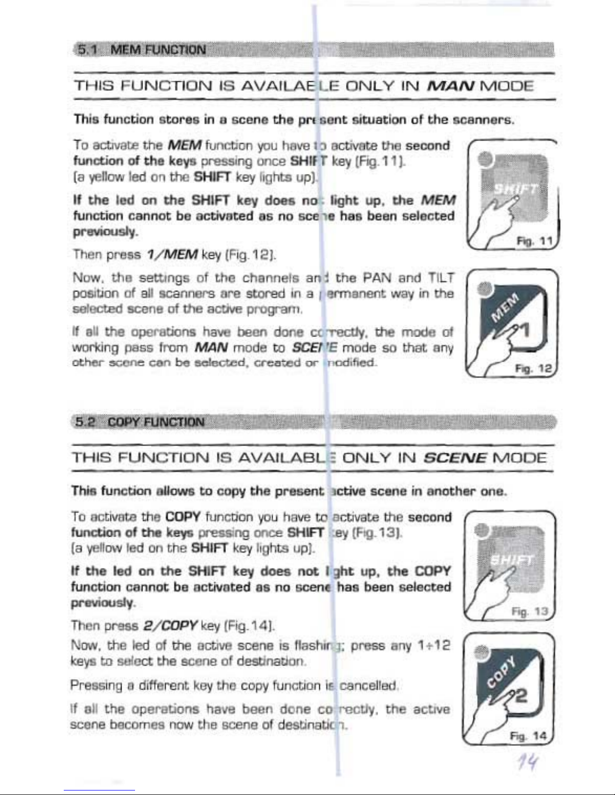
To
~
the
MEM
fur1ct>on
I"U
NMlt"
0CWIIt.a
lh6
""""",
d
function
oi
ths
"
1"1
P'-'ll
orce
&HlfTkllY
IFto 11
~
l
a.,.,ee..
Ied""
the
SHIfT kllY
rogtu
",,1
Il
tIte
1
""
on _ &HIFT k...,
.....
nD.
Iight
up. _
MEM
func:tion
cannet
ba
aot:ilIllted • •
no
"""
.,.
Il••
ba
an
&eIecUd
.......
Then
preu
1/
MEM '-ey (F
lg
12
1-
Now.
tha
settmg
s el tI>e cll.
nn"'.an
l
thft
PAN a
n<!
T1L
T
~
uon
Dt
aii
H<:aIYW'II
_ !ItoNld in a l
""""""'"
WW; in
the
_.,.,.,a
Dt
lh6
1ICtII/II
1I"DIT"'".
Weli
ee
tlpeOaboo
..
have _ dona CO"'eCIIy.
the
mxIa
ltl
worI<ir1l1
pass rrom
MAIV
mode ti> SCEt'E mocle
""
that
a
"'Y
......... ...,.,...,
can
ba
o I
wt
.
cn:.r
-""
<J'
" <xl",,",,
TH I8
FU
NCTIO
N 18
AVA
lLABl.E
ONL
Y
IN
SCENEi
M
ODE
TIliHtunction
......
ti>
""I'Y
tha
prao.ant
oc:tiva
sc
_ in
_h
...
""a
.
To 8OtMIUIltlo COPY
tunet>on
jOt.l
h<J\/Il
te /ICbvat8
tha
sacond r
---
,
Iunaion
of
lho
k
...,.
~
cnc.-.
SHIFT
:8'J
(1'1\1
131
(a .,.,rcw Iad
lin
tt>e
SHl
FT
ke'y
hgtlts ""1.
" _
led
""
_ SHIFT key
__
not
I Jht
UJl
. _
COPY
funcoon
""""Dt
b.
lOC1i.roU,d
• • no
BCenI
Ilo. _ n _
.......
Then
prou
2
/CDPn
""
(R{!.1
41.
N<M',
tha
led d
lfle
lICtnI!I
5<:enII
'"
_
I'J;
P"""" 0"'1 1.1<,
Iulya te
"'
act
t.ha ocene of
desli
natlOn
Pre
llGlfl
g • d
,lIll
rent k"l'
tIl
.
cof'Y
fur
1Ctll<1
if,
~
nc
"'
Bd
It . M
the
Dp8I'lltions
lUMI
!>een
""
Ile
ce f"9CUy.
the
lICtIw
SCHI"IfI
baI;orn
..
now
th.
8<>'J'le
01
deDtinatoc
n.
..
..

THI
8 FU
NC
T ION 18 A
VA
ILA
B LE
ONL
Y IN
PROG
MODE
fig .
15
This functian allows
ta
ch
oose
the length of
the
active program,
arrather
the lastp
erfonned
scene of the program .
Ta activate the LENGTH functian you nave ta acuvate the second
functi
an of
the
keys pressing once SHIFT key (Fig.
15)
.
la yellow led on the SHIFT key tightsup).
It the led on
the
SHIFT key does
not
light up, the
LENGTH
functi
ancannot
beactivated
as
no progra m ha s be
en
select
ed
pr-evicuely.
Then p
res
s 3/LENGTH key (Fig
.16]
.
New. the led of
thethe selected leng
tll
isf1ashing; press any
1+
12
keys
ta
setect a new length of the program.
Pressing a diff
ere
nt key the operati an is cancelled.
Fog. 16
TH
I8 FU N CT
IO
N 18
AVA
ILABL
E ON
LY
IN
PROG
MO
D E
Fig. 17
Then p
ress
4/REPEATkey (Fig.
18).
New,
the
led cer
res
panding ta the setected number of
re
petitio
nsis
tla
shing;
pressany
1
-:-
12 ke
ys
te seleeta
new
value.
This fun
ctian
all
ows
ta
selectthe
number
of
repetitions
for
each
progr
am.
Ta activatethe
REPEATfunction you have ta activare the second
function of
the
keysp
re
ssing o
nce
SHIFT
key[Fig.17].
(a yellow led an the SHIFTkey lightsup).
If the led on the
SHIFT key does
not
light up, the REPEAT
fun
cti
on
cannot
be
activated
as no
program
has been
selected previously.
Pressing a different keythe o
per
atian is cancelted.
Fig. 18
rrn.
fur>ction allows
to
blHCk-out d eh.
5C
snnors
.
Prus
12
/0lACK0Uf
k"'l
to
&tllrt
aO" n
the
n""",al
workW>g.
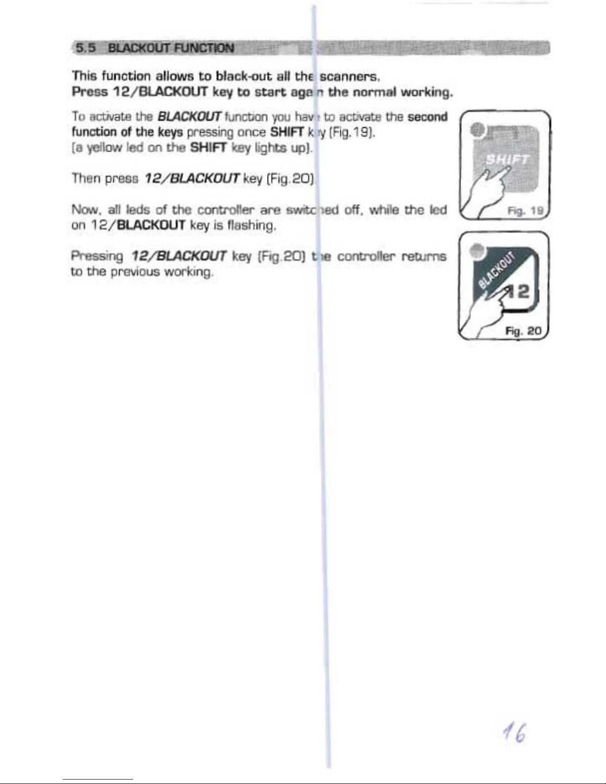
Tu
~
It-.
8
/.AC1<
OOT
II.n::l>i:rl
'/OU
hav. lOectMlllIlhIl
GaCOf'Ol
r-
--,
function ot!ha k
eyo
pressilg
O/'II;;e
SIt/FTk "{{
F"tg.
19).
(a
yeJkJw
lIId
<In ltoIl
SHlfT
Icey
!ig
IU
up)
ThII
np......u 12
/BLA
CKDUT
I<ev
(FIQ_20J
Now
...
Iad&
of
the
CUlb "''''''" ...... ....-c'''''' otf.
wIlIle
lhu
led
011
12/
BlACKOU
T kllY is fteshiflg,
PI-essmg 12
/9I.ACK
OUT kay (Hg
20)
t
..
co-otroIIer
returre
l.o
the
pr'9ViChJ8
workong
fG

A program is a range of scenes (max 12) performed in succession. To create
[or
ta
modify) a program follow
aII
steps listed below:
1) If the
contr
oller is switched off, switch it on pressing POW key.
2) Press
PROG key
ta
activare the
PROGRA
M function.
(the red led on the same key will light up].
3) Using 1
+
12
keys selectonly the program that you want
ta
modify.
(only one program is
f1
ashing].
4) Press
SCENE
key
ta
act
ivate the SCENEfunction.
[the red led on the same key will light up].
5] Using 1
+
12
keys selectthe scene that you wanttamodify.
6) Press
MAN keyto activate the
MA
N+SCENE function.
(the red leds on the
MANand
SCENE
keys will light up].
7] Using 1+
12
keys select one or
mor
e scanners and modify the position
wit h
thejoyst
ick
and the setsof
the
channels wi
th
the CH.SEL. key
and the slider.
8) Once the scann
ers
have been selected and the scene has been cornpleted,
it can be
st
ore
d using
the
MEM
funct
ion:
press
SHIFT key and than
1/ MEM key [see par. 5.1).
9) Now the
contr
oller is again in the SCENE function in order
that
you can
select anothersceneor
copy
the
scene
alreadydane in
ano
ther
one
[seepar. 5.2)..
10) Once the
creat
ian of the scenes has been finished press PROG key
ta
came back ta the PROGRAM functian.
[the red led an
the same key willligth up).
11 ] Finally. you should
set
the length of the
pro
gram using
the
LENGTH
function:
pre
ss once SHIFT key
than
the
3/LEN
GTH key fallawed by
the number of the last stared scene [see par. 5.3).
The program is finished; ta create ar modify others repeat again aii the abave
steps.
/1

It

This
function
activates
some
special
functions
for
the
control
of
the
scanners
and
the
setting
of
the
DMX
2012
controller.
To activate the MENU function you have to activate the second
function of the keys pressing once
SHIFT
key [Fig.21].
[a yellow led on the SHIFT key Iigh
ts
up].
Then press
9/MENU
key (Fig
.22
].
Naw
aII
the
lights of
the
ca
ntra
ller are switched aff, while the
leds an MUStC and
SHtFf
keys stay an
ta
indicatethat
in the
MENU
functions
the
se keys became ESC (MUSIC) and OK
(SHIFT).
As saan as this
funct
ian is activated, the LCD display shaws
the
first
functian available..
By
CHANNEL
SELECT keys
or
by
theslider
yau can select
between the
MENU
functians available, which are:
RESET
SCANNER
: It activates
RESET
functian for onear more scanners * (par.7.2)
LAMP ON: It turns
ON
the lamp of one ar more scanners * (par.7.3]
LAMP
OFF:
It turns
OFF
the lamp of one ar more scanners * (par.7.3)
CLEAR
PROG/SCENE:Itc1e
ars the contents of a program ar a scene (par.7.4)
EDIT
SETUP
: It
allows
ta modifyaIIthe active
SETUP
parameters ** [par.7.5)
LOAD
L1BRARY
: It loadsa
SETUP
from internal
scanne
r Iibrary ** [par.7.6)
Ta exit
fram
MENU
functian press ESC [MUSIC)key.
Ta
act
ivate
the
selected functian press OK (SHIFT)key.
For
the
specific
description
of
the
MENU
functions,
see
the
related
sections.
* It will wark only if the scanner is predispased for this functian.
** This functian madify
thewor
king pa
rame
ters
of
the
con
tro
ller, sa IT
MUST
BE USED ONLY BY QUALIFIED PERSONNEL.
/9

M~U:FPNctl(J!\I$
;rf!l;$t
t$cI!.NNi
"
~
!
§!iiti»
AV
AILABL
E ONLY
AmR
THE
ACTIVATlOII
OF
THE MENU
FUNCTIO
NS {par
.?1)
ALLOWS ro RESET ONE OR MORE
se
lNNERS
.
(ooly it
the
sele
cted
scannerare pr-ecis tceed
for
this
functian).
This functian mustbe
performed
when tbe scanners Iose synchronization
ar
they don't perform
the
commands of the :antro
lle
r in a correctway.
Ta activate
thi
s funetian you have
ta
ente - the
MENU
functions
ţ
v.p a
r.
7.1).
Through the CHANNEL SELECT keys ar by the slider yau mustseleet on the
display the "RESET SCANNER" functian.
Pressing OK (SHIFT)
the
functian ie enter sd.
"SELECT SCANNER" appears on the
dis~
ay, through the 1/ 12 keys you mu
st
select
the
scanners(1
/12]
on which ya 1 w
ant
ta
p
erform
the
functi
an.
The lightson the 1/ 12 keys indica
tes
the selected scann
ers
.
The scannere selected will remain in memory, sa
that
when we witl perform
this function aqam. we will already have
tt
3 same seleeted scanners.
Pressinq ESCkeyyou
exit from MENU
func
-ion
s without performing anyoperatian.
Pressing OK key the RESET funetion is ac Jvated
for
6 seconds.
TECHNICAL NOTES;
RESET tunc
tlcn
sends for 6 seco
nds
1"
defined reset value
ta
aII the
20
channels of the seiecteo scanner-s.
To modify
tne
res
et value for each ebat nel you must p
erl
orrn
EDIT SETUP
fun
ct
ian.
ATIENTlON:
Ifthe sc
anner
is notpredis rcsed
for
thi
s fu
nction,
it will never-
p
erformare
set
.

).
n

AV
Al1..ABLE
CNl.Y A
FTER
THE
ACTlVA
TOl
CF
THE
MENU
FUNCT
DNS
[pal".7.1)
ALLDWS ro
CLEARAPROGRAM
IF EN' FRED FROM
PROGRAM
MODEOR ro
a.EAR
A SlNGt.ESCENEIF ENTFREDFR"JM SCENE OR
SCENE.MAN
MODE.
NOn:: IICtivating th
is
Iu
nctlOO
wtlrie thl cootronfll" is performing
PROGRAM
mod
e a
oMlOle
progr-am
lS
c1eared (
12
se
mes
).
Activating t his
lunction
whila the c mtr otler i8 pertor
mm
g SCEN E O
I"
SCENE-oMAN
mod
e a
singIe
eceoeiscJ
eYed
To aetrvate th
os
tunaioo
you haV8W eree -
ee
MENU
IUrl(."tions fv.per.7.1).
Ttrough
tne
OiANNEL
SEtECT
keys o- by
thll
ssoe-
you
must
seIect an
the
diapley
ee
-cLEAR PAOG
/SCEN
E-
flrct
an.
Pr-essing
OI(
[SHIFT) h lunctio n ;9
cntcr'!d
.
"Sf
LfCT PROGRAM- Dt" "SELfCT SCEl\ E"
~
an
the
di6play,
through
tho
1/ 12 keys you mu
st
u l
ect
the
prag am/ _ ne 11/ 1
2)
ta
de
al".
Tha
lIghts
an
ee 1
/1
2 keys indIcates thf: &eIaction
an
the
dl&pl8y
"aJ:AR
? ESC
/OK-
i1pp88"Si.
Presslng OK
key
the
pl1lQl81II
/acene
WllI
oe
clfIered
PrasMIg ESC kl!!'/
YOU
uo!. from MENU
1'Unc1..ms
WChol.t.
pell
Di
'IM.g aoy operation.

....
__
..
""""""
_
....
_
..
_-_
....
.-
_
__
_
__
_
..-01
. _ _
..
.....
-,
_
......
_
...
,---
.Tr
o,,'_I
_""'mt<
lII'
llIf
SETLO'...........
,.""."'
/VO
r
I'ffC'lO
IN
~
• ' 11'
""r
.l'AfYOM'!I
"'"
WWWC7Jl1-..s
ro
~r
,
1.
_ <ha
__
....
_
"'
"NU
"""""""1 J
, ~
""-
...
_
afUC"
_ _
........
_
...
__
....
~-
-
"'-'a
lllt
19'1Ffl
....
"",,",,"._
..
u:CT~
__
"'
.... _
;_
V
'2
....
_
............
11/121
'"'
_ _
-..
..
_ _ ,
"'"
_'"'
"'"
'1·2
....
-..
...
_-.-.
"'-
llIt
m,,,,_.
_
___
...
_
............
_ '"_.....
__
~
Itl.e:ItO-
:;.._ •
...
---_
..
_--
..
..
-
...
1'OE
1fUC'Jto_
......_
1'OE_
.a.
_
....
_"
__
_1
__
,..--
..
_
...
_
OOl.
".."..
_Es:J
_ ....
"""
__
....
_""
"'<0_
'-""_ID
_
..
__
""'
...
--
_
...
_-_
__
...
_
......
-
......
-
..
"'-
,.
ID
~
....
""'"
la
..-
.......
__
.
"""'9'
..
__
-
....
"
..
....
_,..-
__
...........
,."...."
-_
..
__
,
"'"
_
__
"""
__
M
"""I
'"
_
...
......
- - 1"'"
"""""'.
~
_
..-..
......
_
....
-..
~
oen.
..
_ _ _ _ _ •
..-
.,.,
....
......
lIlR
SEU'
--
..-....
....
_-_
.......
__
""""
_
..
-
..
....",
Of(
...
.....,.
"
•••
~
""
"',
""
_ '
.....
, .
--",
--_
....
--,,"',
""
-""""
",,--
~
....
l:HoW'ti
lIUCl'
_
"'"
_
..-...
...
_
"'"
ora
......
__
-.
..
_ O_
",
_
",
~"
,
_ _ ....
!'se
_ .CW1tfOI. _
..
...
_
""'_
...
__
__
..
""-~
...
,
..
_-",,
-_
...
...-
_
_-_
....
_,-
,.
-
....
-
-
._
-1
\

"> Pressing OK the cnenne! displayed becon e active and we
start
te
modify the channet
parameters.
The controller uees these special channefs for
r-e
defined functions, yoo must use them f
or
the
specific functions assignedtothem.
NOf
USED
.> Net usedchannel.
PAN
.> Pan channel (
SOFT
CR
OSS/HARD
::nos
SJ.
PAN lOW ·> Pan channel
lDW
.
nLT .>
Tilt
channet l
SOFT
CROSS
/HARD
:ROSS
).
TIlT
LOW->Tilt
chann
ellDW
.
LAMP
.> Lamp con
tro
l channel.
LAMP/RES ·>
L.i
ke
LAMP
.
The veue change between two scenes can be nmediate {
HARDCROSS
)
OI"
gradual
(SO
FT
CIIDSS)•
•> Through the
CHANNELSELECT
keys or
by
th slider
you
can
moclify
change mode,
HAR
D
CROSS
Of"
saR
CROSS
[except for the scec
er
fi nction channels.
In
which)OU
jlJffiP
dlre
e:tly
te
rnodification of the
BlKOUT
value].
•> Press
OK
to
modlfy "Bl K
OUTVAl-
that is th~value of the channel wnen the B
LACKOUT
functionis activeIpar.55).
You can
eelecc..:::
:::(unchang
ed] value or O /
25
j value. The ::::::= value is selected ptJtting the
s1id
er
te
O andit allowste maintain un
chang
edthe Jutput value (no bfeckout for this channel).
.,.
Prese
(J(
te
mod
ify"RESETVAL" tnet a the
~
Ilue of the chennel when the MENU:
RESET
functicnis
active
(I/
.pa-
.7.21.
You
can
serect
..... lunchangedl value OI" O /
25
1 value. The ..... value is
selec
ted putting the
slide-
te a andt
ellows
te maintainuncllanged the J
i.4lUt
value(no reset far this channel).
Only
itthe lAMP
OI"
lAMP/RES
channel
is s
eecee
1; press
OK
te mo
::My
LAMP
ON
veue. Press
OK
agaÎntemod;fy
LAMP
OFF
vaIue.
"'"
PreS5ing
OI<
ogain
you
renen becktethe
chal1l
els
seeceon
andthe
arrow
">. is pasitioned
on me le
ftofee
channelnumbar.
New
you
can seect ancdler
channel
forthe
modific
ltion.
NOTE
: Pr1nising OK key without rmving CHANNf ..
SELECT
Iteys and the slider you can scro!l
between cha nnel parameter& without any modffic.tion.
ro
STORE
ALLnE
MOOlACAT
XJNS,REAO
THE
S CTDN BELDN.
TO
EXIT
FRDM
EDIT
UPFUNCTION
To exitfrcm this funetion
yoo
needro press ESt: keywhen
you
ere in e e channelselection
when
the arrow ">" is onthe left of
the
number It channel lpressing
ESC
keywhen
yOO
are
modifyi
ng cha
nr18
1peremete-e. ycu retom back ro the chamels selection. $O you have
ta
Pf'ElGS
ESC
key
again}. .,
When
"SAVE?ESC
/OK" appeers on the displa' : Pressing OKaII
the
modif
lC8tions·ARE
STDREO
IN
MEMORY
and the con
troller
exits f -cm Ula
EOrT
SETUPfunction.
Pressing
ESC
, "EXil?
ESC
/OK" sppeers an the lis
play
;
~
'JOU
want
II)
exit
from
dlis
fUn
ction
WITHOUT
STORINGTHE
MOO!FICATIONS
prese OK. otherwise p-ese
ESC
ta
retum
to
the
channe
lse
lection.
NOTE
: EOrr SETUP function
ecte
an
the
con
trt ue
r's
memor)'
and
OOES NOT
mod
ify
the
Ii
br'aryof sceooe-setcps .

AVAILABLEONLY
AFT
ER T
HE
ACT
IVATION
OF
THE MENU FUNCTIONS (par.7.1 )
AUDWS
TO LOAD A SETUP FROM LlBRARY
AND
STOREIT IN
MEMORY
.
To activate this function you have to enter the MENU functions (v.par.7.1).
Through the
CHANNEL SELECT keys
or
by the slider you
must
select on the
display the "LOAD
L1BRARY
" function.
Pressing OK
(SHI
Fn
the function is entered.
"SELECTSCANNER" appe
ars
on the display, through the
1/
12
keys
you
must
select
the
scanners(1/12)
on which you
want
to
perform
the
functian .
The ligh
ts
on the 1/
12
keys indicates the selected scanners .
Pressing
ESC
key
you exit from MENU functions without performing anyoperation.
Pressing OK key the function is aetivated.
The display shows
the
tirst
scann
er
in the Iibrary, through the
CHANNEL
SELECT keys or by the slid
er
you can seleet the right type of scanner [ar an
equivale
nt
) from the Iibrary.
Onee se
lec
ted the
scanner .
press
ing
OK app
ears
on
the
display
"SA
VE?
ESC/OK
".
Pressing OK the SETUP of the selected scanner is loaded in the memory of
the controller and activated for aIIthe selected scanner.
Pressing ESC appears an the display "EXIT ? ESC/OK"; if you want ta exit
from this function WITHOUT
ANY
MODIFICATION press OK key, otherwise
pressing ESC key you retu rn back to the selection of the scanner.
NOTE: If inside the SETUP Iibrary there isn't y
our
scanner
ar
a compatible
type, you
must
configure manually the SETUP of the controller, using the EDIT
SETUP functian (par.7
.5)
.
The SETUP UBRARY is a range of SETUP [scanner) that can
not
be modified,
but
only read.
Through LOAD L1BRARY functian yau can eopy the SETUP of the scanner
from the Iibrary to the internat memory of the c
ontr
oller.
To modify a SETUP yau must s
tareitin memary thraugh the LOAD
L1BRARY
function and
aft
er modify it through the EDIT SETUP funetion.


Technical
features
:
Number
of scanners controlled separately:
12
Number of channels for each scanner:
20
N
umber
of stared programs:
12
Nu
mber
of scenes for each program:
12
Total number of scenes:
144
(12
program
s x
12
scenes)
Positioning way of the m
irror:through
a Joys
tick
(fix
or
proport
ional m
irror
speed)
Channel
features: Pan-Tilt 8
/16bit-Hard/Soft
cross - R
eset
- Lamp
Setup: Load
from
internal libraryormanual setup.
Technica/
features:output
signa/
Kind of output signal:
DMX512/
1990
Outputconnector: 5-pin cannon
connector
Max number of scanners connected ta the DMX output :
32
Number of DMX channels:
240
(20
ch. x
12
scanners)
Technica/
features:storageofprogram
and
settings
Kind of storage / size: FLASH
memory2Mbit
Data maintenance withoutpower supply: >
40
years
Climatic condition
for
the
use
Humidity:
35%
+
80%
Temperature : 5 +
50
°C
Power
supp/y
Voltage/ current:
12
Vdc /
240
mA
Technical
fetures:aud
io inp
ut
Source: Inside
throughabuilt
-in microphone / outside
throughastereo
jack
Sensitivity / input impedance: O dB
(775
mV) /
50
Kohm
Kind of level adjustment:
Autom
atic
Dimensions and we
ight
Dimension
(W
x L x H) /
Weight:482x88x65
mm (2U rack) / 1,6Kg.
CODEM MUS/C S.r./
. -
Str
. Pano
ram
ica
Adr
iatica,
10/
C- 6 11
00
PESARO
-ITALY
Tel. +38
07
2 1
24638
- Fax
+380721
22CXJ42
http://www
.codemmusic
.com-&me
il:codmus@tin.it
AII rights reserved. No parts of this document can be copied. photacopied or reproduced without
the prior wnttenperrnissionof the CODEM MU51C s.r.I.
No responibility is taken for possible inaccuracies ar mistakes.
The
caDEM
MUSIC s.r.I, reserves the right ta make any alterations ar aesthetics changes of this
produet that seem necessary at any time and for whatever reason.
The
caDEM
MUSIC s
.r
.l, takes no responsibility for the use or for the application of this produet.
 Loading...