

Page 1

USER MANUAL
RACK UPS
1 - 10 KVA
Page 2

2
Page 3

3
USER MANUAL
Rack Series
1 - 10 KVA
Page 4

4
About The Manual
This manual is prepared for the users of Rack Series 1-10 kVA.
Companion Manuals
For further information about this device and its options, please visit www.LEGA.com
Updates
Please visit www.LEGA.com for updates. Always use the latest manuals.
Thanks for using our products.
Please strictly obey all the instructions in this manual and pay attention to all the warning and
operation information. It is not advisable to install or operate the machine before reading this
manual.
Page 5

5
CONTENTS
1 SAFETY INSTRUCTIONS ................................................................................................................ 7
2 INSTALLATION INSTRUCTIONS ................................................................................................. 8
2.1 Unpacking Inspection ........................................................................................................... 8
2.2 Attention Items of Installation .......................................................................................... 9
2.3 UPS and Battery Pack Rear Panel View ............................................................................. 9
2.3.1 The Type of 120V (Output could be 100V, 110V, 115V, 127V) ................................... 10
2.3.2 The Type of 220V (Output could be 208V, 210V, 220V, 230V, 240V) ......................... 11
2.4 UPS Output Connection ................................................................................................... 12
2.5 External Battery Connection Procedure For Long Back Up Type ..................................... 12
2.6 Installation....................................................................................................................... 13
3 PANEL FUNCTION and OPERATION ........................................................................................... 15
3.1 Keys Function ..................................................................................................................... 15
3.2 LED Function....................................................................................................................... 17
3.3 LED Display Function.......................................................................................................... 17
3.4 Turn On/Off Operation ....................................................................................................... 19
3.4.1 Turn On Operation .......................................................................................................... 19
3.4.2 Turn Off Operation ................................................................................................ .......... 19
3.5 UPS Self-Test / Mute Operation .......................................................................................... 20
3.6 Panel Function Setting ........................................................................................................ 20
3.6.1 ECO Mode Setting ............................................................................................................. 20
3.6.2 Bypass Mode Setting ........................................................................................................ 21
3.6.3 Output Mode Setting ........................................................................................................ 22
3.6.4 Low Voltage of Battery Setting ........................................................................................ 23
3.7 Parameters Inquiring Operation .......................................................................................... 24
4 WORKING MODE INTRODUCTION ............................................................................................. 26
4.1 Bypass Mode ....................................................................................................................... 26
4.2 Line Mode............................................................................................................................ 26
4.3 Battery Mode ...................................................................................................................... 26
4.4 ECO Mode ............................................................................................................................ 27
4.5 Fault Mode. ......................................................................................................................... 27
5 THE WARNING LIST OF THE LOGHT and DISPLAY PANEL ................................................... 28
6 TROUBLE SHOOTING ................................................................................................................ 31
Page 6

6
7 ATTETTION BOF BATTERY DISPOSAL ....................................................................................... 33
8 NETWORK COMMUNICATION .................................................................................................... 33
9 COMMUNICATION INTERFACE INTRODUCTION ....................................................................... 33
10 GUARANTEE .............................................................................................................................. 39
10.1 Terms of Guarantee ............................................................................................................ 39
10.2 Cases Not Covered by the Guarantee................................ .................................................. 40
11 CONTACT INFORMATION ......................................................................................................... 44
Page 7

7
Do not touch the battery connection terminals. Battery loop and input voltage loop is without
isolation, which may cause high voltage risk between the battery terminal and ground.
Do not connect to the equipment like hair dryer or electric heater, to ensure the safety for
UPS
1 SAFETY INSTRUCTIONS
The power output voltage may still have 220V or 120V even not connect to the mains power.
For the battery cable or power cord replacement, please contact our service station or
dealer to purchase, in order to avoid fire caused by inadequate capacity or heat ignition.
Do not place the battery or battery pack in the fire, which will injure due to explosion.
Please do not open the UPS case as you will, there is risk of electric shock
the
Page 8

8
2 INSTALLATION INSTRUCTIONS
2.1 Unpacking Inspection
Open the UPS package, please check the enclosed accessories including a user manual,
communication cable, support feet, CD-ROM. The long-back model also includes the cable for
connection to battery bank.
Check the UPS if any damage in transport. If find it’s damaged or parts missing, do not power
on, please turn to the carrier and dealer.
To determine whether this UPS is the model you want to buy. Check the model name showed
both on the front panel and rear panel of UPS to confirm.
Model
Type
Model
Type
1KVA
1KVA Standard model
1KVA
1KVA Long backup model
2KVA
2KVA Standard model
2KVA
2KVA Long backup model
3KVA
3KVA Standard model
3KVA
3KVA Long backup model
6KVA
6KVA Standard model
6KVA
6KVA Long backup model
10KVA
10KVA Standard model
10KVA
10KVA Long backup model
NOTE:
Please save the packaging box and packaging materials for future transport use. As heavy
product, please transit the UPS with care.
Page 9

9
2.2 Attention Items of Installation
The UPS installation environment must be with good ventilation, away from water, flammable
gases and corrosive entities.
Do not lie down the UPS against the wall so that front and side panel air intake hole, rear panel
air outtake hole will be unobstructed.
The peripheral environment temperature around the UPS should be within 0 ℃ ~ 40 ℃.
If dismantling the machine at low temperatures, there may be condensation droplets, users can
not install or operate it before UPS completely got dry both inside and outside, otherwise there
will be danger of electric shock.
Place the UPS near the mains socket to cut off AC mains without any delay at any emergent
case.
ATTENTION:
Make sure the load behind the UPS is off when users connect the load to UPS, and then turn on
the load one by one later.
Please connect the UPS with the socket which is over-current protected. Do not connect the
UPS with the socket which rated current is less than the Maximum input current of the UPS.
All the power socket should be configured with earthling device for safety.
UPS could be electrified or powered no matter the input power cable is tied or not, even when
the UPS is off. The only way to cut off the output is switching off the UPS, disable the EPO and
disconnecting the mains power supply.
For all standard type UPS, it is advised to charge the battery over 8 hours before used. Once the
AC mains power energizes the UPS, it will automatically charge the battery. Without prior
charging, UPS output remains as usual but with shorter back-up time than normal.
When connected to motor, display equipment, laser printer etc, UPS power selection should be
based on the startup power of the load which is usually twice as rated power.
2.3 UPS and Battery Pack Rear Panel View
NOTE:
Following diagrams take the type of 0.9PF for example, the type of 0.8PF is similar.
Page 10

10
2.3.1 The Type of 120V (Output could be 100V, 110V, 115V, 127V)
A. Standard Model
2 3 4 5
6
2
11 7
8
S
S
EPO
FUSE 250VAC 35A
RESET
FUSE 125VAC, 15A
RESET
USB
INP UT OUT PUT
L N N L
INPUT
9 1
OUTPUT SOCKE T
10
IN OUT
TEL/MODEM/FAX
8
7
OUTPUT SOCKET
9
10
6 5 4
a. 0.9PF 1KVA rear panel b. 0.9PF 2KVA&3KVA rear panel
B. Long-Run Model
2 3 4 5
6
9
2 3 4
7
ON
INTELLIGEN T SLO T
S
EPO
FUSE 125VAC, 15A
RESET
USB
INPUT
OUT PUT
OFF
L N L N
INPUT
9 1
OUTPUT SOCKE T
10
IN OUT
TEL/MODEM/F AX
8
7
11
5 8 6
a. 0.9PF 1KVA rear panel b. 0.9PF 2KVA rear panel
2
10
3
4 6
9 9
S
FUSE 125VAC,35A
RESET
INPUT OU TPU T
L N N L
+
72VDC 40A
-
EXT.BATTERY
OUTPUT SOCKET
EPO
INTELLIGENT
SLOT
9 11 8 5
7
c. 0.9PF 3KVA rear panel d. 0.9PF Battery Pack rear panel
+
-
INTELLIG
ENT SLOT
INTELLIGE
NT SLOT
+
24VDC 40A
-
EXT.BATTE
RY
+
24VDC 40
A
-
EXT.BATTERY
IN
OUT
TEL/MODEM/FAX
RS232
US B RS232
RS232
72VDC 40A
EXT.BATTERY
EPO
IINNTTEELLLLIIGEENNTT SSLLOTT
USB
RS232
RS232
EPO
USB
IN
OUT
TEL/MODEM/ FAX
DC OU TPUT
DC OU TPUT
+
72VDC -
+
72VDC -
Page 11

11
2.3.2 The Type of 220V (Output could be 208V, 210V, 220V, 230V, 240V)
A. Standard Model
2
4
5 6
8
3
7 1 2
S
EPO
INTELLIGENT S LOT
S
FUSE 250VAC,8A
RESET
USB
INPUT
FUSE 250VAC, 20A
RESET
INPUT
OUTPUT S OCKET
IN OUT
TEL/MODE M/FAX
+
48VDC 40A
-
EXT.BATTERY
9 1
10
3
8
7
6 5 4
OUTPUT SOCKE T
10
9
a. 0.9PF 1KVA rear panel b. 0.9PF 2KVA rear panel
9
2
3
4
7
8
3
7 1 2
ON
INTELLIGENT SLOT
INTELLIGENT SLOT
S
INPUT
FUSE 250VAC, 20A
RESET
OFF
OUTPUT SOCKE T
+
72VDC 40A
-
EXT.BATTERY
6 5 4
10 9
11
5 8 6
c. 0.9PF 3KVA rear panel d. 0.9PF 6/10KVA rear panel
B. Long-Run Model
2
4
5 6
2 1
4 6
S
EPO
S
FUSE 250VAC ,8A
RESET
USB
FUSE 250 VAC,15A INPUT
RESET
INPUT
OUTPUT S OCKET
IN OUT
TEL/M ODEM/F AX
+
48VDC 40A
-
EXT.BATT ERY
OUTPUT S OCKET
EPO
INTELLIGENT
SLOT
9 1
10
3
8
7
9 10 8 5 7
a. 0.9PF 1KVA rear panel b. 0.9PF 2KVA rear panel
9
2
3
4
7
2 1
4 6
ON
INTELLIGENT SLOT
S
FUSE 250 VAC,20A INPUT
RESET
INPUT OUTPU T
OFF
+
72VDC 40A
-
EXT.BATTERY
OUTPUT S OCKET
EPO
INTELLIGENT
SLOT
L N L N
9 10
8
3 5 7
11
5 8 6
c. 0.9PF 3KVA rear panel d. 0.9PF 6/10KVA rear panel
1. Input Power Terminals
2. Over Current Protector
3. Fan
4. USB
5. Emergency Power Off
6. RS232 Communication Interface
INTELLIGENT SL OT
INTELL IGENT
SLOT
+
24VDC
40A
-
EXT.BA
TTER
Y
+
24VDC 40A
-
EXT.BA
TTER
Y
OUT
IN
TEL/MODEM/FAX
IN
OUT
TEL/MODEM/FAX
RS232
EPO
USBB
USB
RS232
RS232
RS232
OUT
IN
TEL/MODEM/FAX
IN
OUT
TEL/MODEM/FA X
RS232
EPO
USB
EPO
EPO
USB
USB
USB
RS232
RS232
RS232
INP
UT
OU
L
N
L
N
Page 12

12
7. Intelligent Slot
8. Surge Protection for
Network/Fax/Modem
9. Battery Slot
10. Output Socket
11. Terminal Block
NOTE:
Diagrams take the type of 0.9PF for example, the type of 0.8PF is similar. Due to the technology
upgrading and development, goods and diagrams might have some differences.
Page 13

13
INPUT
OUTPUT
L N
N L
which rated current is less than the UPS’s maximum input current. Otherwise the receptacle may
be burned and destroyed.
Over Current
Protector
Battery
ON
Over Current
Protector
OFF
Battery
Input
output
LOAD
Input
output
2.5 External Battery Connection Procedure For Long Back Up Type
For different UPS type, users are instructed to configure different battery voltage as below
sheet. More or less units are forbidden, or else something abnormal or faulty will appear.
2.4 UPS Output Connection
Output connection of 1~10KVA type is configured with sockets or terminal blocks, users can plug
the load cable into the UPS socket to energize the load as below. Make sure the mains wire and
breakers in the building are enough for the rated capacity of UPS to avoid the hazards of electric
shock or fire.
NOTE:
To the type of 6-10KVA, do not use the wall receptacle as the input power source for the UPS,
Type
Battery Quantity
(unit)
Battery Voltage
(volt)
1KVA
2/3
24/36
2KVA
4/6
48/72
3KVA
6/8
72/96
6KVA
16
192
10KVA
16
192
One end of battery cable is for UPS terminals while the other end with triple cables is for battery
terminals. Correct installation procedure is highly vital or else probable electric shock will arise.
Users are strictly required to follow the below procedure.
Connect battery in correct way and make sure the total battery voltage is available for UPS.
OUT
IN
/MODEM /
Page 14

14
m
Correctly connect the long battery cable to battery terminals first, red wire is to positive plate
while black is to negative. If users connect the UPS first, electric shock or other danger could not
be avoided.
Before connecting load after UPS, users should supply main power to UPS and energize it.
Connect long battery cable to UPS terminals with correct poles link
(red is for “+”, black is for“-”), UPS will start the charging work automatically.
+
S
RED
-
+
-
FUSE 125VAC,20A
RESET
INPUT OUTPUT
+
48VDC 40A
-
EXT.BATTERY
Battery
L N N L
OUTPUT
BLACK
+
+
-
+
-
-
+
-
2.6 Installation
UPS installation work should comply with local electrical standard and only can be done by
professional technician. 1KVA~3KVA units could use wall socket as input power connection.
For all type UPS, it is advised to charge the battery over 8 hours before the first use. Once the AC
mains power energizes the UPS, it will charge the battery automatically. Without prior charging,
UPS output remains as usual but with shorter back up time than normal.
Installation steps:
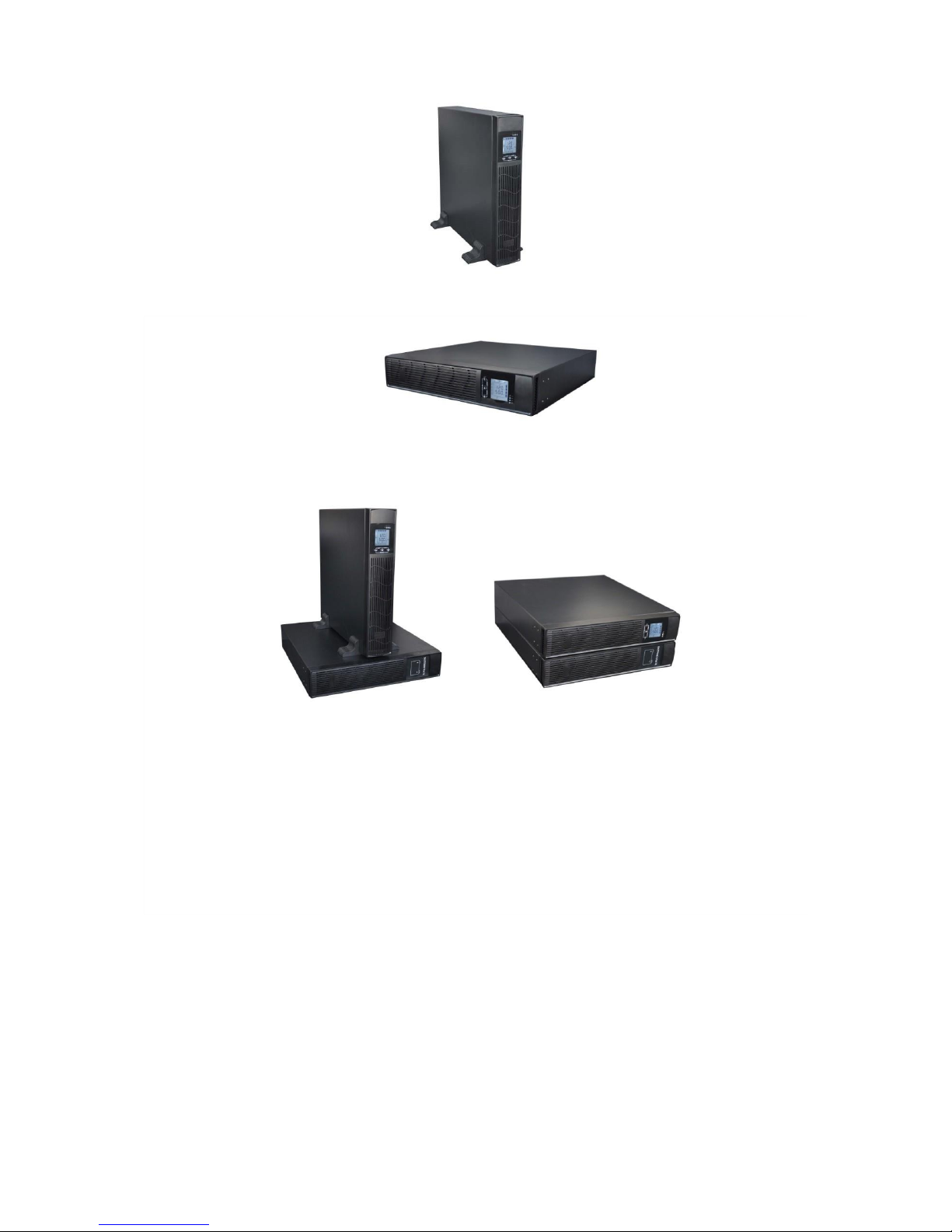
1. Please take out two groups of support feet from package, assemble by embedding them with
each other as shown below.
2. Place the two support feet in parallel on horizontal surface, and then put the machine into
two support feet carefully. Make sure the main power is off when you move it.
Page 15
15
the battery pack should be put under the machine. The battery pack is heavy, be careful when
you move it.
3. It also can be placed horizontally without support feet if you like, please remember not to put
the machine upside down. Please lie it down carefully and make sure the main power is off.
Page 16
16
3 PANEL FUNCTION and OPERATION
The operation is simple, operators only need to read the manual and follow the operation
instructions listed in this manual without any special training.
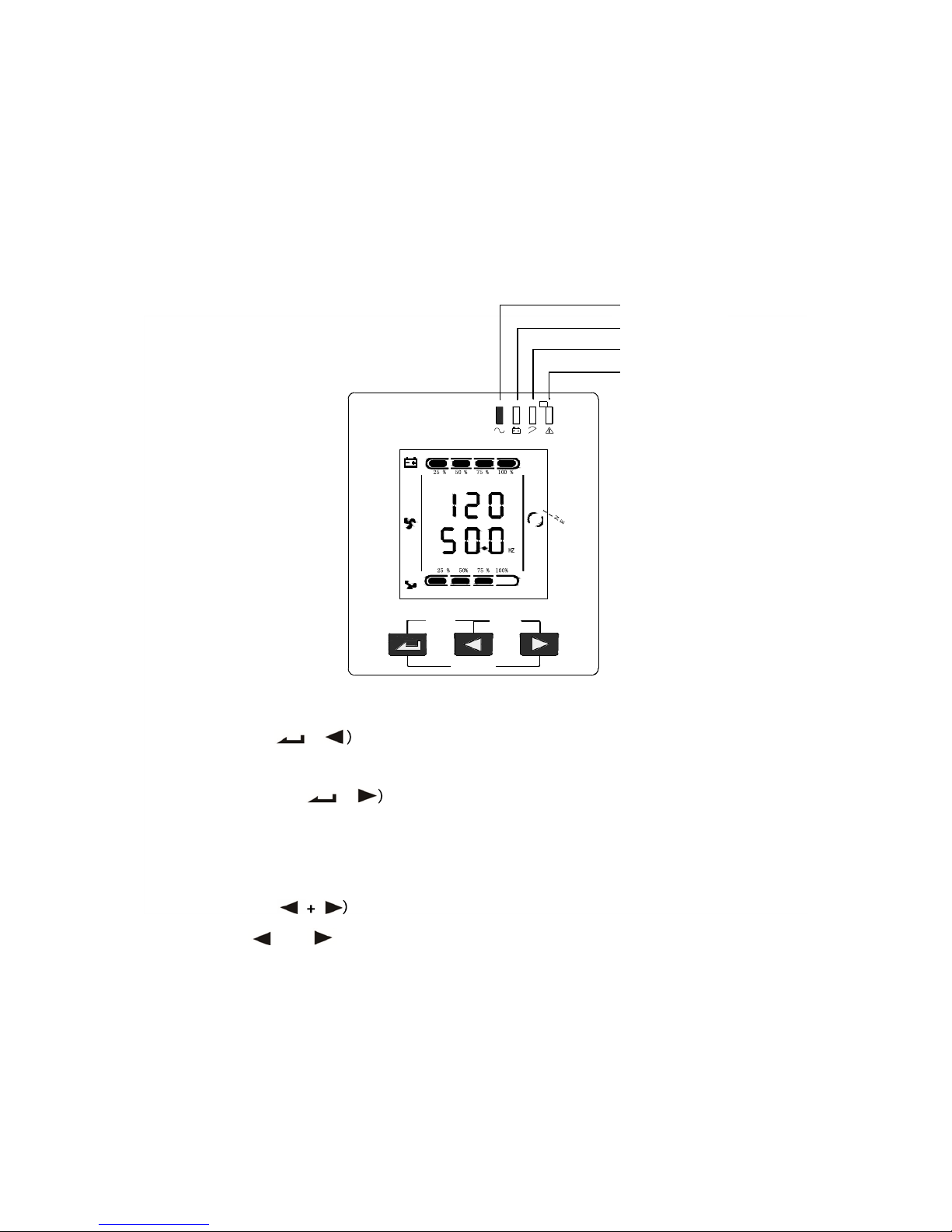
3.1 Keys Function
Press and hold and for more than half a second (less than 2 seconds): Change the
direction to display items.
Inverter LED
Battery LED
Bypass LED
Warning LED
ON/OFF
ROTATE
TEST/MUTE
※ ON/OFF key (
+
Press and hold this key for more than half a second to turn on/off the UPS.
※ TEST/MUTE key (
+
Press and hold the key for more than 1 second in mains mode or economical mode: UPS runs the
self-test function.
Press and hold the key for more than 1 second in battery mode: UPS runs the mute function.
※ ROTATE key (
VAC
OUTPUT
Page 17
17
25% 50% 75% 100%
VAC
HZ
OUTPUT
25 % 50% 75% 100%
ON/OFF ROTATE
TEST/MUTE
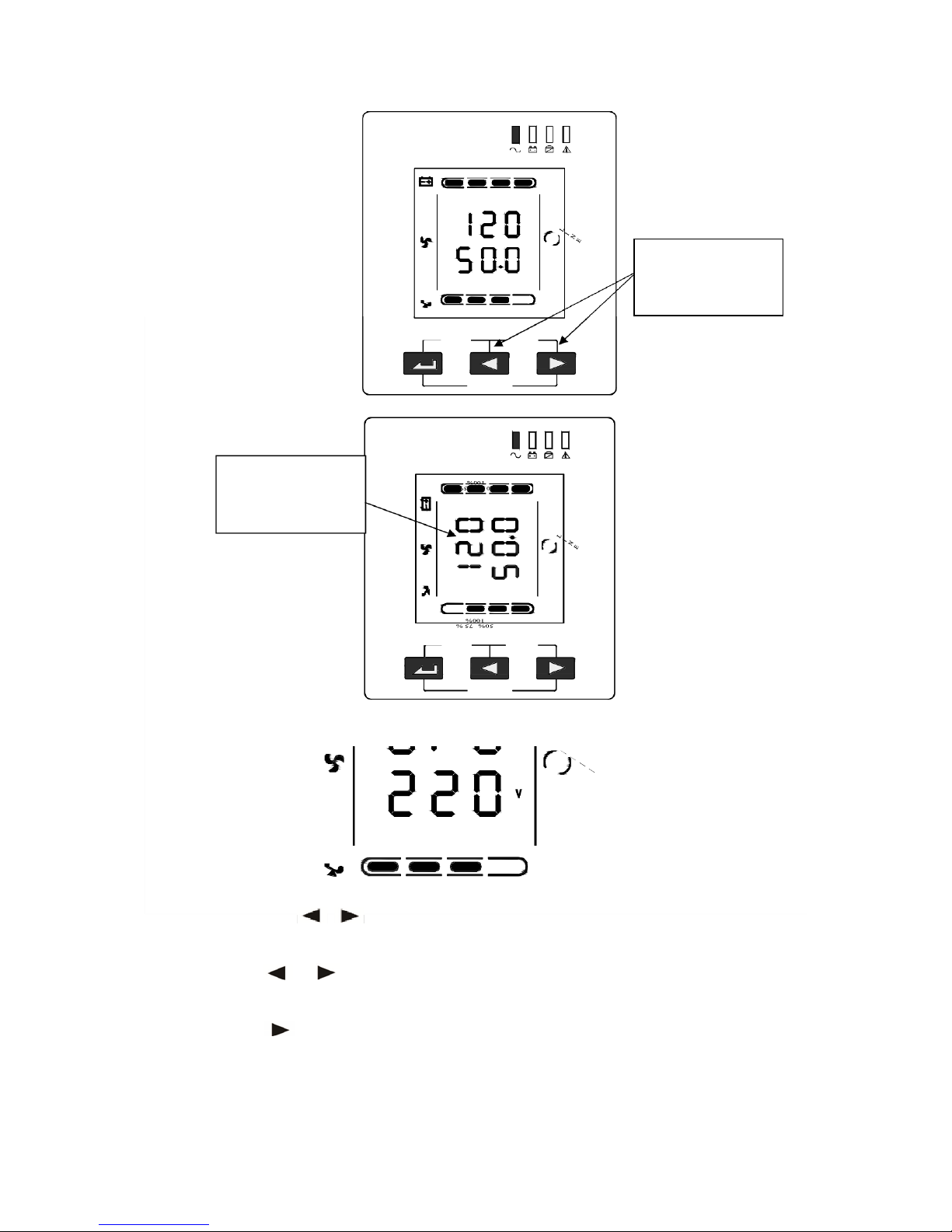
The direction has
been changed in the
picture.
ON/OFF ROTATE
TEST/MUTE
After finishing that, the machine can be placed flat, as shown in the picture below.
25 % 50 %
75%
10 0%
※ INQUIRING key ( , )
Non-function setting mode:
1) Press and hold
or
for more than half a second (less than 2 seconds): display the items
orderly.
2) Press and hold for more than 2 seconds: Circularly and orderly display the items every 2
seconds, when press and hold the key for some time again, it will turn to output status.
Press and hold keys
for more than half a
second.
2
5
%
2
5
%
OUTP UT VAC HZ
Page 18

18
Function setting mode:
Press and hold the key for more than half a second (less than 2 seconds): Select the set option.
※ FUNCTION SETTING key
Non-function setting mode:
Press and hold the key for more than 2 seconds: Function setting interface.
Function setting mode:
Press and hold the key for more than half a second (less than 2 seconds): Enter the function
setting option
Press and hold the key for more than 2 seconds, exit from this function setting interface.
3.2 LED Function
From left to right is inverter LED, battery LED, bypass LED and warning LED.
Warning red LED is on: UPS fault. For example: Overload beyond the allowed time, inverter fault,
BUS fault, over temperature fault etc.
Bypass yellow LED is on: UPS is alarming. For example: Bypass mode supply power and etc.
Battery yellow LED is on: UPS is alarming. For example: Battery mode supply power and etc.
Inverter green LED is on: UPS is normally powered by mains or ECO mode or battery mode.
PS: LED display detail in different mode is listed in 5 items.
3.3 LED Display Function
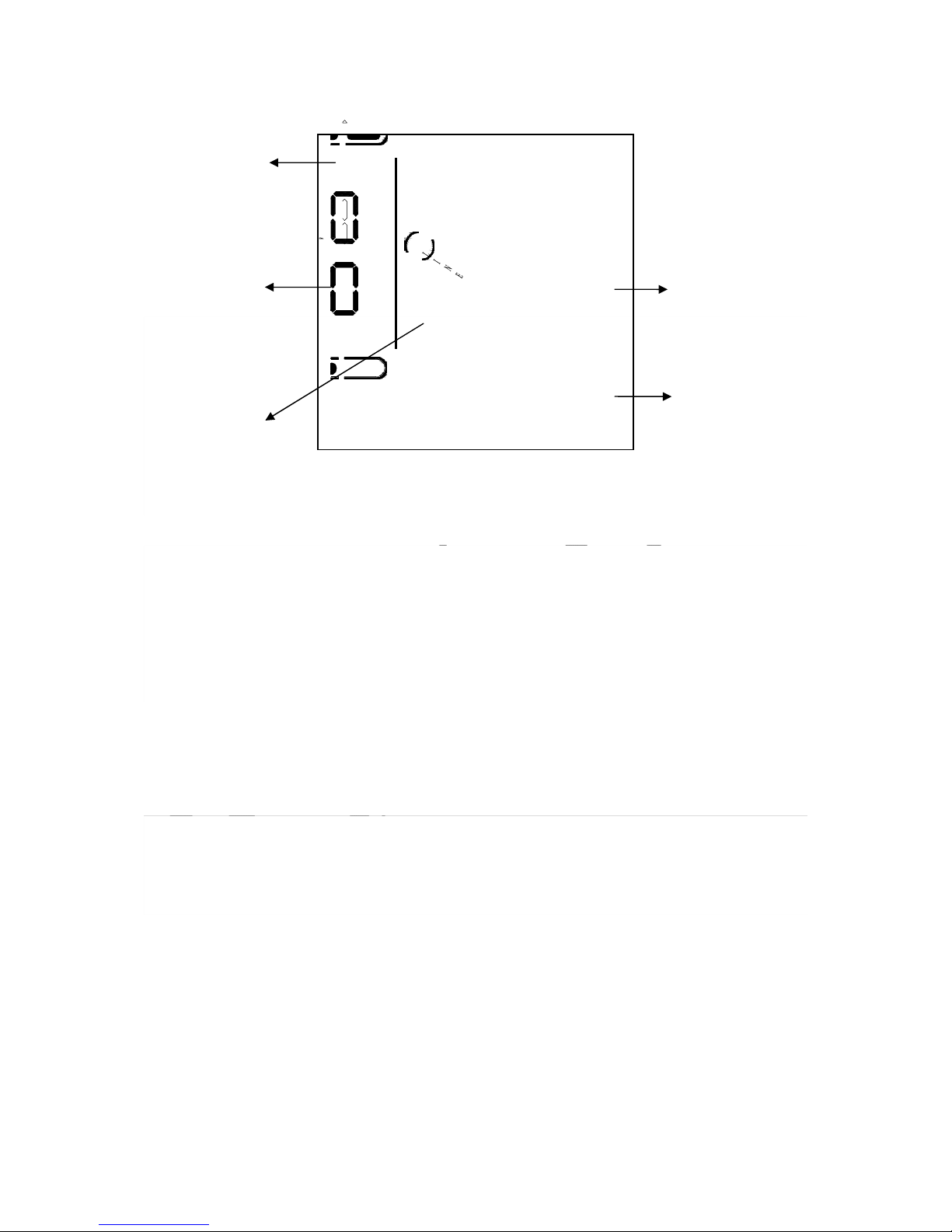
LCD displays as following figure.
※Icon display area:
1. The top diagram is for load, battery, fan, fault and buzzer icon. When UPS is over loaded, the load
light will blink as same as the battery light blinks when the capacity of battery gets low or battery
is disconnected. The left icon and right icon are for load and battery capacity indication, each grid
of which represents 25%.
2. The fan icon is for fan working indication; when fan normally runs, the icon will display rotation; if
the fan is not connecting or faulty, the icon blinks;
3. Press the mute button under the battery mode, buzzer icon will blink; it will disappear under
other cases.
4. Fault icon will be on when UPS on fault mode, otherwise it will not.
Page 19
19
Icon display area
100%
Load capacity
display area
VAC
HZ
Battery capacity
display area
100%
Working mode
display area
Digital display area
※ Digital display area:
Under none setting mode, it will display UPS output information when UPS normally runs in AC
mode; other information like input, battery, load and temperature will be showed after
pressing the inquiring key; Fault code will be told in fault mode.
Under setting mode, user could adjust different output voltage as well as activate ECO and
BYPASS mode by operating function setting key and inquiring keys.
※ Mode display area:
After over 20 seconds, this area will display the working mode of the machine. e.g. STDBY(Standby
Mode), BYPASS(Bypass Mode), LINE(AC mode), BAT(Battery mode), BATT(Battery Self Test Mode ),
ECO(Economic Mode), SHUTDN(Shutdown Mode).
Page 20

20
3.4 Turn On/Off Operation
3.4.1 Turn On Operation
A. Turn on the UPS on Line mode
Once mains power is plugged in, the UPS will charge the battery, at the moment, LCD shows
that the output voltage is 0, which means UPS has no output as default condition. If it is
expected to have output of bypass, you can set the bps “ON” by LCD setting menu.
Press and hold the ON key for more than half a second to start the UPS, then it will start the
inverter.
Once started, the UPS will perform a self-test function, LED will light and go out circularly and
orderly. When self-test finishes, it will come to line mode, the corresponding LED lights, UPS
is working on line mode.
B. Turn on the UPS by DC without mains power
When main power is disconnected, press and hold the ON key for more than half a second to
start UPS.
The operation of UPS in the process of start is almost the same as that when mains power is in.
After finishing the self-test, the corresponding LED lights and UPS is working on battery mode.
3.4.2 Turn Off Operation
A. Turn off the UPS on line mode
Press and hold the OFF key for more than half a second to turn off the UPS and inverter.
After UPS shutting down, LED go out and there is no output. If output is needed, you can set
bps “ON” on LCD setting menu.
B. Turn off the UPS by DC without mains power
Press and hold the OFF key for more than half a second to turn off the UPS.
When turning off the UPS, it will do self-testing firstly. LED light and go out circularly and
orderly until there is no display on the panel.
Page 21
21
3.5 UPS Self-Test / Mute Operation
When UPS is on line mode, press and hold the self-test/mute key for more than 1 second, LED
light and go out circularly and orderly. UPS comes to self-test mode and tests its status. It will
exit automatically after finishing testing, LED resume.
When UPS is on battery mode, press and hold the self-test/mute key for more than 1 second,
the buzzer stops beeping. If you press and hold the self-test/mute key for one more second, it
will restart to beep again.
3.6 Panel Function Setting
UPS has setting function. It can run the setting on any mode. After setting, it will become effective
at once when meets some standards. The set information can be saved only when the battery
connected and normally turning off the UPS.
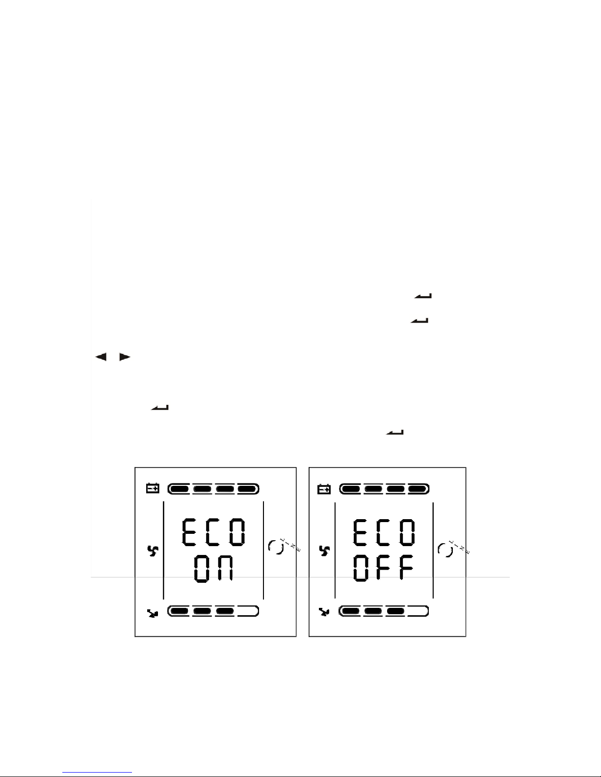
3.6.1 ECO Mode Setting
Enter the setting interface. Press and hold the function setting key for more than 2
seconds, then come to setting interface, the letters “ECO” will flash.
Enter the ECO setting interface. Press and hold the function setting key for more than half a
second(less than 2 seconds), then come to setting interface of ECO, at this time, the letters “ECO”
will light for a long time. The “ON” (or OFF) will flash. Press and hold the inquiring key(
, )for more than half a second (less than 2 seconds) to determine whether the ECO
function is used or not. If used, the corresponding word is “ON”, if not, the word is “OFF”. It can
be determined by yourself.
Confirm the ECO selecting interface. After selecting ON or OFF, press and hold the function
setting key for more than half a second (less than 2 seconds). Now, the ECO setting
function is completed and the “ON” or “OFF” will light without flash.
Exit from the setting interface. Press and hold function setting key for more than 2
seconds, exit from the setting interface and turn to main interface.
25% 50%
75 %
100%
25 % 50 % 75 % 100%
25 % 5 0 %
75 %
100% 25 % 50%
75 %
100%
Page 22
22
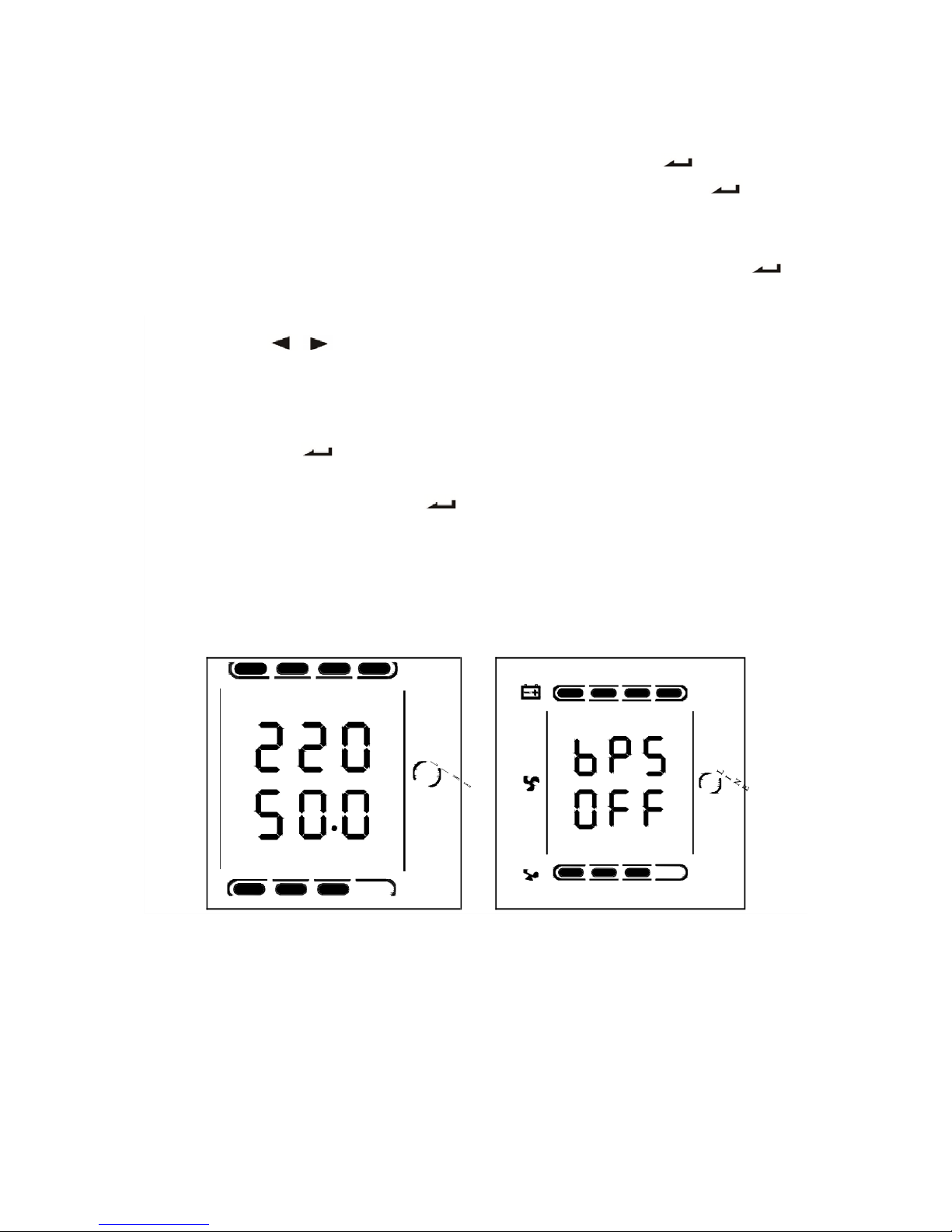
3.6.2 Bypass Mode Setting
Enter the setting interface. Press and hold the function setting key for more than 2
seconds, then come to setting interface, Press and hold the function setting key for more
than half a second(less than 2 seconds), select the function setting, choose the bypass output
interface, at the moment, the letters “BPS” will flash.
Enter the Bypass output selecting interface. Press and hold the function setting key for
more than half a second(less than 2 seconds), then come to setting interface of BPS, at this
time, the letters “BPS” will light for a long time. The “ON” letter will flash. Press and hold the
inquiring key( , )for more than half a second (less than 2 seconds) to determine
whether the BPS function is used or not. If used, the corresponding word is “ON”, if not, the
word is “OFF”. It can be determined by yourself.
Confirm the Bypass output selecting interface. After selecting ON or OFF, press and hold the
function setting key for more than half a second (less than 2 seconds), Now, the BPS
setting function is completed and the “ON” or “OFF” will light without flash.
Press and hold function setting key for more than 2 seconds, exit from the setting
interface and return to main interface.
After setting BPS as ON, when mains power plugged in without turning on the UPS or no mains
power plugged in, there is bypass output but no power down backup function.
25 % 50 %
75 %
10 0 %
25% 50 %
75%
100%
VAC
HZ
INPUT
25% 50 %
75%
100%
25% 50%
75 %
10 0 %
Page 23
23
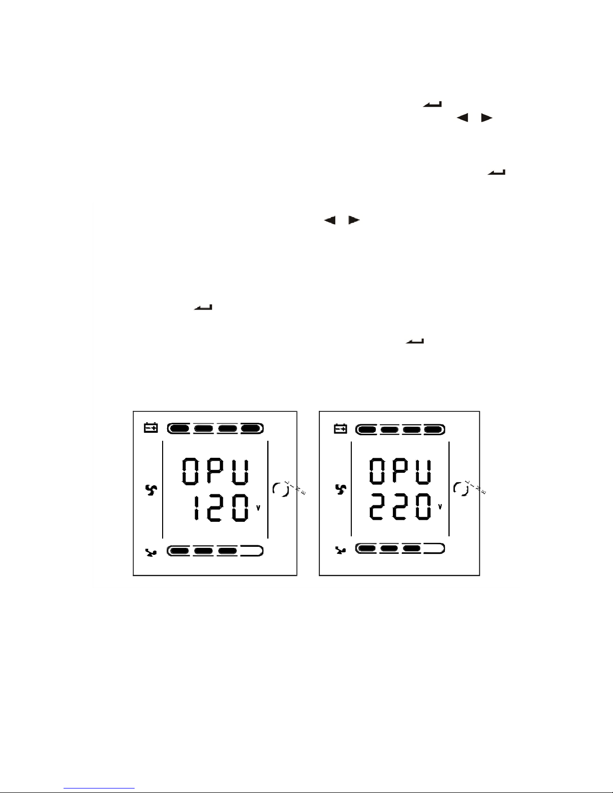
3.6.3 Output Mode Setting
Enter the setting interface. Press and hold the function setting key for more than 2
seconds, then come to setting interface, Press and hold the inquiring key(
,
)for
more than half a second(less than 2 seconds), select the function setting, choose output voltage
setting interface, at the moment, the letters “OPU” will flash.
Enter the output voltage selecting interface. Press and hold the function setting key for
more than half a second(less than 2 seconds), then come to setting interface of output voltage
OPU, at this time, the letters “OPU” will light for a long time. The numerical value below the OPU
will flash. Press and hold the inquiring key( , ) for more than half a second (less
than 2 seconds), select the numerical value in accordance with “OPU” function. The provided
voltages are 100, 110V, 115V, 120V, 127V or 208V, 210V, 220V, 230V, 240V, you can choose
anyone by yourself.
Confirm the output voltage selecting interface. After selecting numerical value, press and hold
the function setting , for more than half a second (less than 2 seconds). Now, the OPU
setting function is completed and the numerical value will light without flash.
Exit from the setting interface. Press and hold function setting key for more than half a
second (less than 2 seconds), exit from the setting interface and return to main interface.
25% 50 % 75%
100%
25 % 5 0 %
75 %
10 0 %
25% 50%
75%
100%
25 % 50 %
75 %
10 0 %
Page 24
24
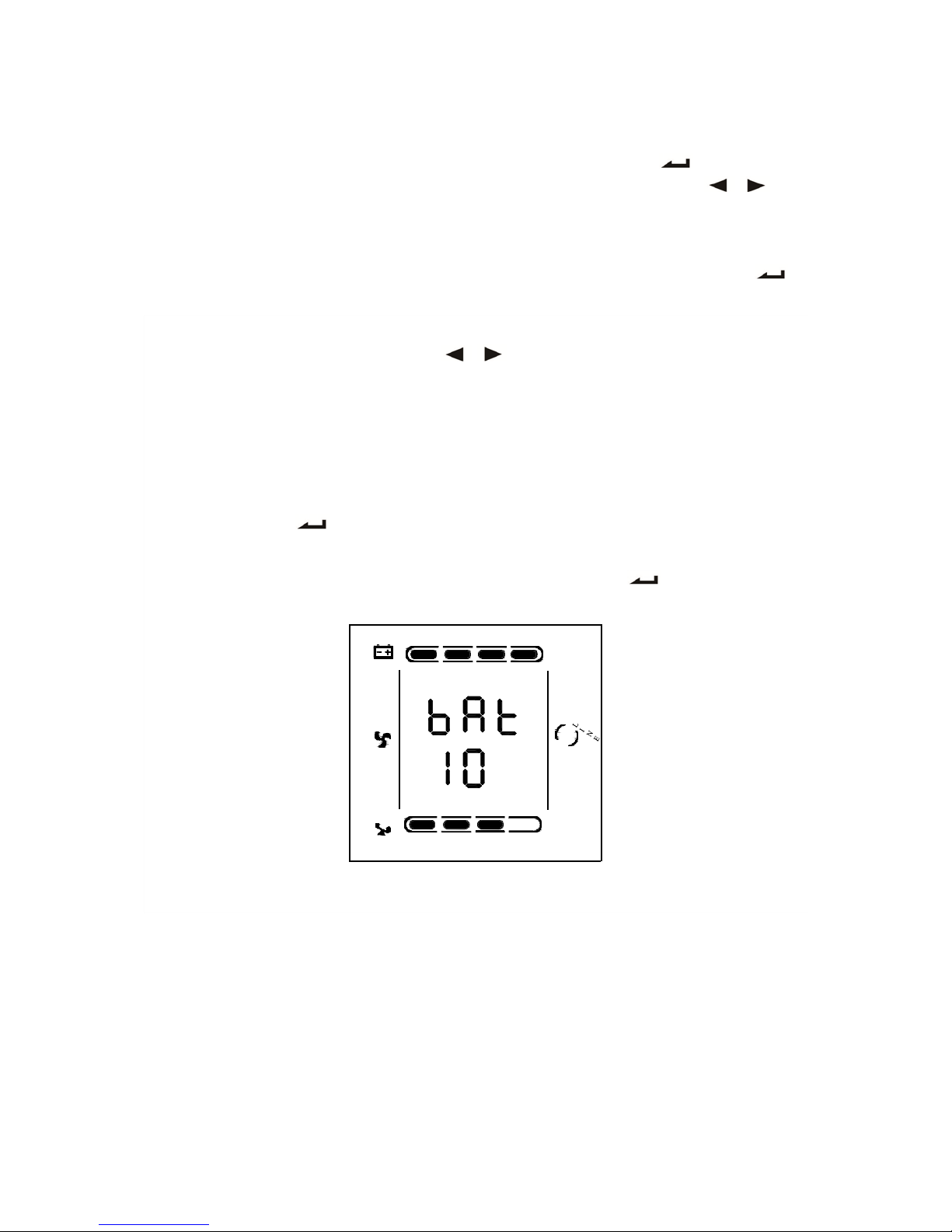
3.6.4 Low Voltage of Battery Setting
Enter the setting interface. Press and hold the function setting key for more than 2
seconds, then come to setting interface, Press and hold the inquiring key(
,
)for
more than half a second(less than 2 seconds), select the function setting, choose battery voltage
setting interface, at the moment, the letters “bat” will flash.
Enter the battery voltage selecting interface. Press and hold the function setting key for
more than half a second(less than 2 seconds), then come to setting interface of battery voltage,
at this time, the letters “bat” will light for a long time. The numerical value below the “bat” will
flash. Press and hold the inquiring key( , ) for more than half a second (less than 2
seconds), select the numerical value in accordance with “battery” function. The provided
voltages are 10V, 10.2V, 10.5V, numbers stand for the voltage of each battery, you can choose
anyone by yourself (The default is 10V), anyone has been chosen, the machine will shutdown
when its battery voltage achieve the voltage which you chose.
Confirm the battery voltage selecting interface. After selecting numerical value, press and hold
the function setting , for more than half a second (less than 2 seconds). Now, the battery
setting function is completed and the numerical value will light without flash.
Exit from the setting interface. Press and hold function setting key for more than half a
second (less than 2 seconds), exit from the setting interface and return to main interface.
25% 50%
75 %
10 0 %
V
25 % 50 %
75 %
10 0 %
Page 25
25
3.7 Parameters Inquiring Operation
Press and hold the inquiring key
or
for more than half a second(less than 2 seconds) to
inquire about items. The inquired items include input, battery, output, load, temperature. The
displayed items on LCD screen are showed as following:
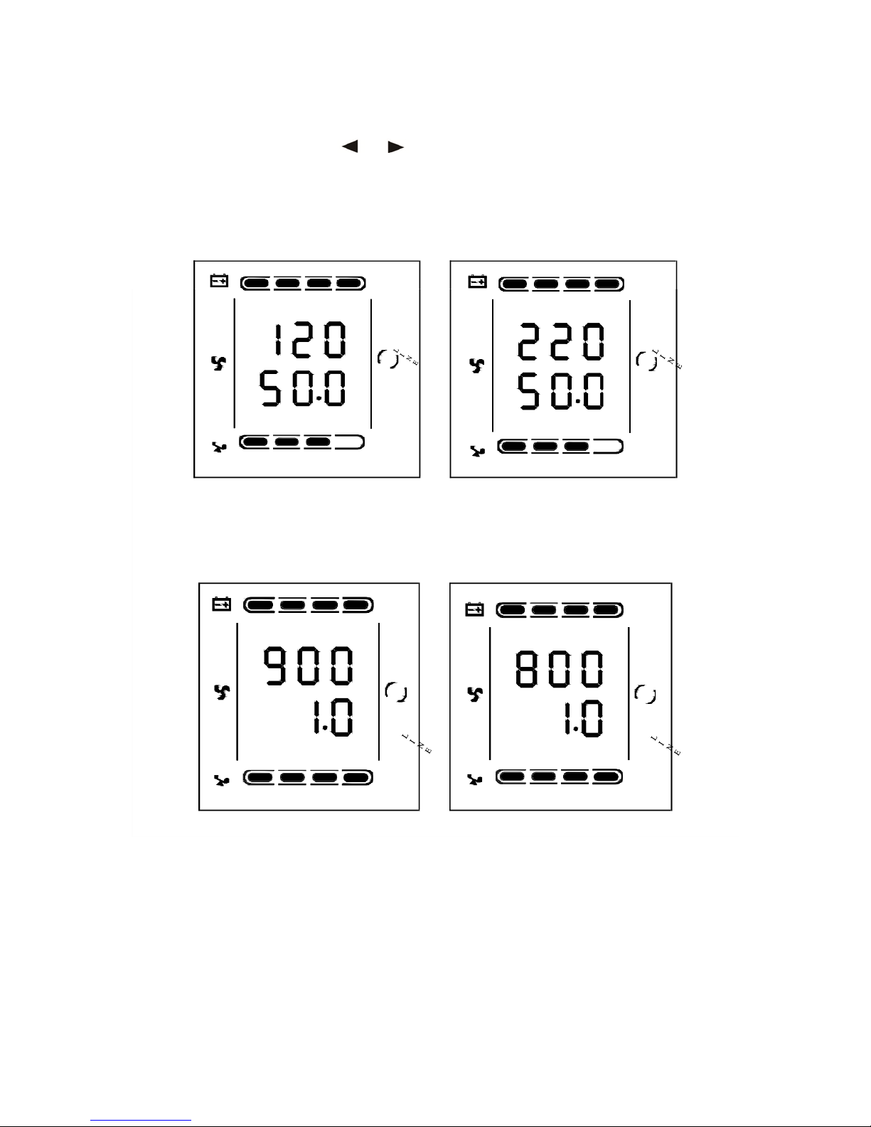
Output:Display the output voltage and output frequency of the UPS. As the following picture
shows, the output voltage is 120V or 220V, the output frequency is 50Hz.
25% 50% 75% 100%
25% 50 %
75%
100%
VAC
VAC
HZ
OUTPUT
HZ
OUTPUT
25 % 50 %
75%
100 %
25 % 50%
75%
100 %
Load: Display the numerical value of the active power (WATT) and apparent power (VA) of the
load. For example, as the following graphics shows: the WATT of the load is 800W or 900W, VA
is 1000VA (when disconnect load, it is a normal phenomenon to show a small numerical value of
WATT and VA). or 900W
25 % 50 %
75 %
10 0 %
25% 50%
75%
100%
W
KVA
LOAD
25 % 50 %
75 %
10 0 %
W
KVA
LOAD
25 % 50%
75 %
100%
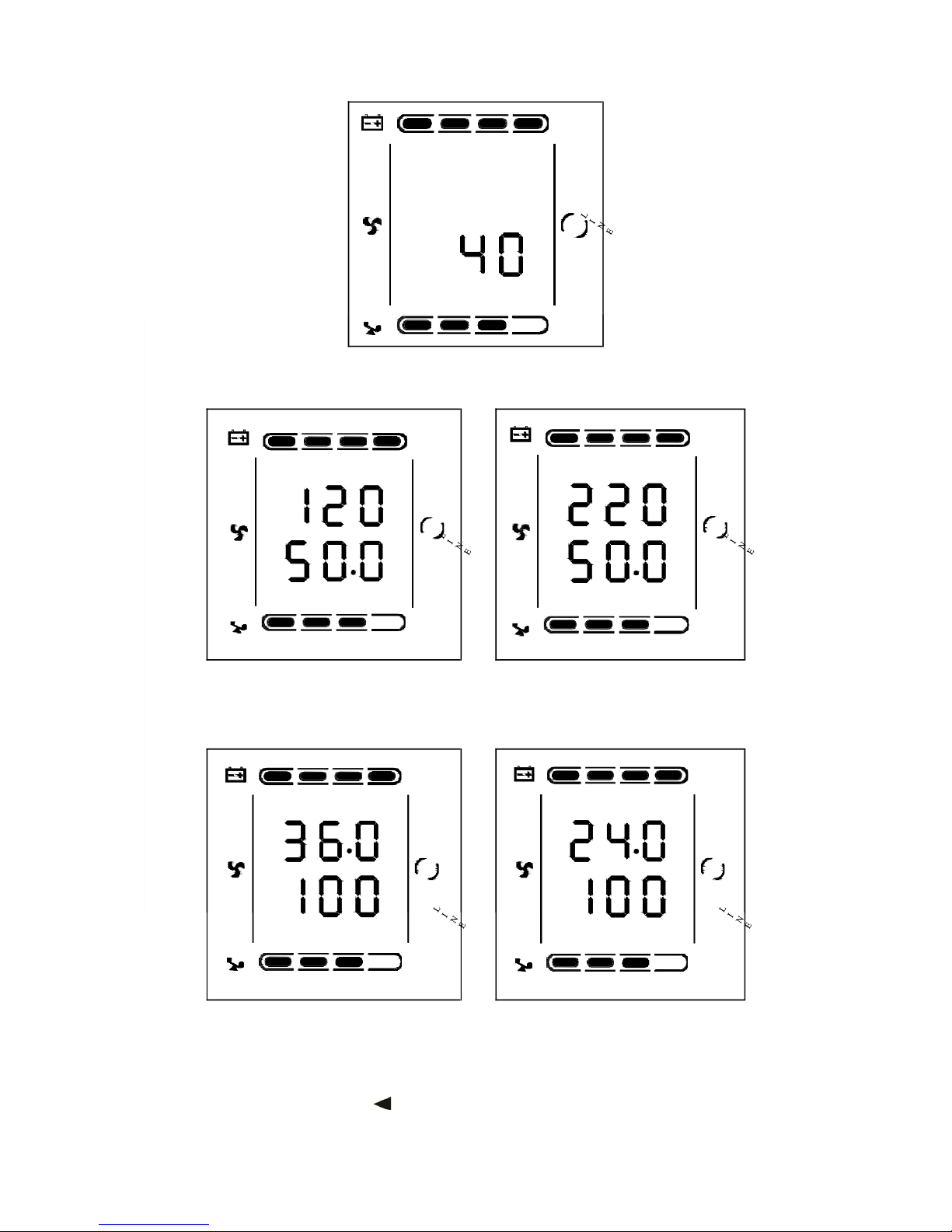
Temperature: Display the maximum temperature of the components in the UPS. As the
following picture shows: the maximum temperature is 40℃.
Page 26
26
Input: Display the voltage and frequency of the input. As the following picture shows: the input
voltage is 120V or 220V, input frequency is 50Hz.
25 % 50 %
75 %
10 0 %
25 % 50 %
75 %
10 0 %
VAC
VAC
HZ
INPUT
HZ
INPUT
25 % 50 %
75 %
10 0 %
25 % 50 %
75 %
10 0 %
Battery: Display the voltage and capacity of the battery (determined by type). As the following
picture shows: the battery voltage is 24V or 36V, the capacity of battery is 100%(the capacity of
battery is approximately reckoned according to the battery voltage).
25 % 50 %
75 %
10 0 %
25 % 5 0 %
75 %
10 0 %
VDC
%
VDC
%
BATTERY
25 % 50 %
75 %
10 0 %
BATTERY
25 % 5 0 %
75 %
10 0 %
Press and hold the inquiring key for more than 2 seconds, LCD begins to display the items
circularly and orderly which transfer to another every 2 seconds. Press and hold the key for
some time again within 30s, it will return to output status.
25 % 50 %
75 %
100%
℃
25 % 5 0%
TEMP
75 %
100%
Page 27

27
4 WORKING MODE INTRODUCTION
4.1 Bypass Mode
LED indications on front panel on bypass mode are as following:
Bypass yellow LED is on, the buzzer beeps once every 2 minutes. The warning red LED is on
when beeping, LCD displays are according to the exact load and battery capacity.
Turn to bypass mode under the following two conditions:
Turn off the UPS on line mode while start the bypass output.
Overload on line mode.
NOTE:
When UPS is working on bypass mode, it has no back up function.
4.2 Line Mode
LED indications on front panel on line mode are as following: The inverter green LED is on.
When input AC is in the range of working conditions, UPS will work on line mode.
4.3 Battery Mode
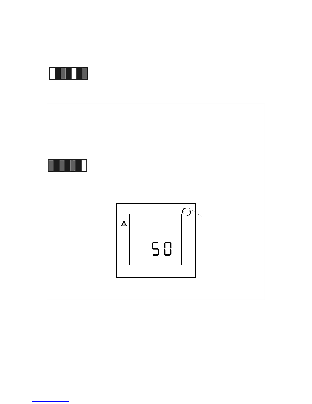
LED indications on front panel on battery mode are as following: both the inverter green LED
and battery yellow LED are on, the buzzer beeps once every 4 seconds. The warning red LED is
on when beeping.
When the AC power is low or unstable, UPS will turn to battery mode at once.
Page 28
28
4.4 ECO Mode
LED indications on front panel on ECO mode are as following: both the inverter green LED and
bypass yellow LED are on.
When the input mains meets the input range of the ECO mode and start the ECO function, the
UPS will works on ECO mode. If input AC exceeds the range of ECO several times in a row in a
minute but stays in inverter input range, UPS will work on AC inverting mode automatically.
4.5 Fault Mode
LED indications on front panel on Fault mode are as following: warning red LED is on and LCD
display fault code and related icon.
Fault mode (LCD interface on which the fault code display)
When UPS has faulted. The warning LED is on and the buzzer beeps. UPS will turn to fault mode.
UPS cuts off the output and LCD display fault codes.
At the moment, you can press the mute key to make the buzzer stop beeping temporarily to wait
for maintenance. You can also press the OFF key to shut down the UPS when confirm that there
is no serious fault.
Page 29
29
Appendix 2: Table for working status
5 THE WARNING LIST OF THE LOGHT and
DISPLAY PANEL
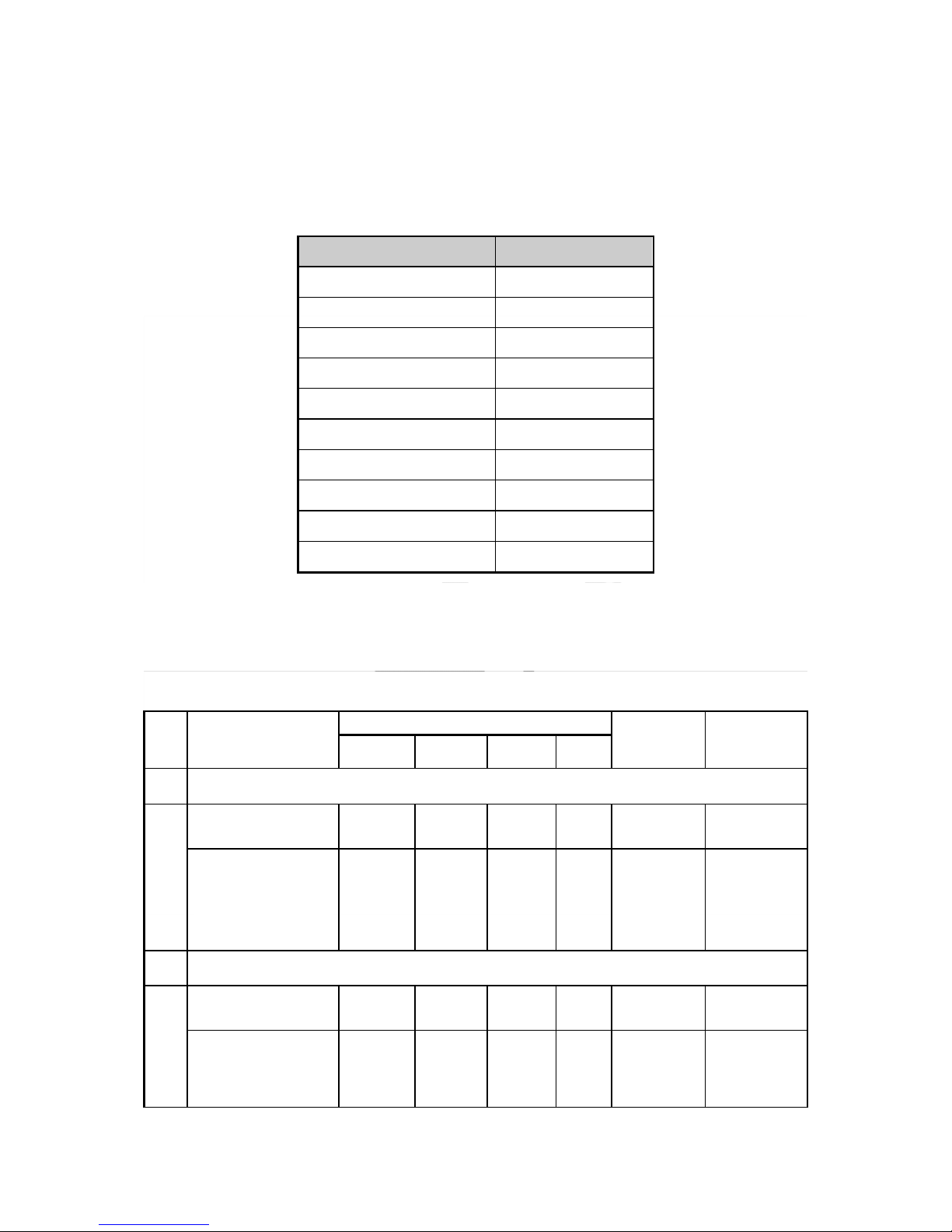
Appendix 1: The table of the fault code
Fault reason
Fault code
BUS voltage fault
00-14
Power soft start fault
15-24
Inverter voltage fault
25-39
Overheat
40-44
Output short circuit
45-49
Overload
50-54
Input NTC fault
55-59
Power fault
60-64
Input FUSE fault
65-69
Other
88
S/N
Working status
LED on Front panel
Alarm
beep
Note
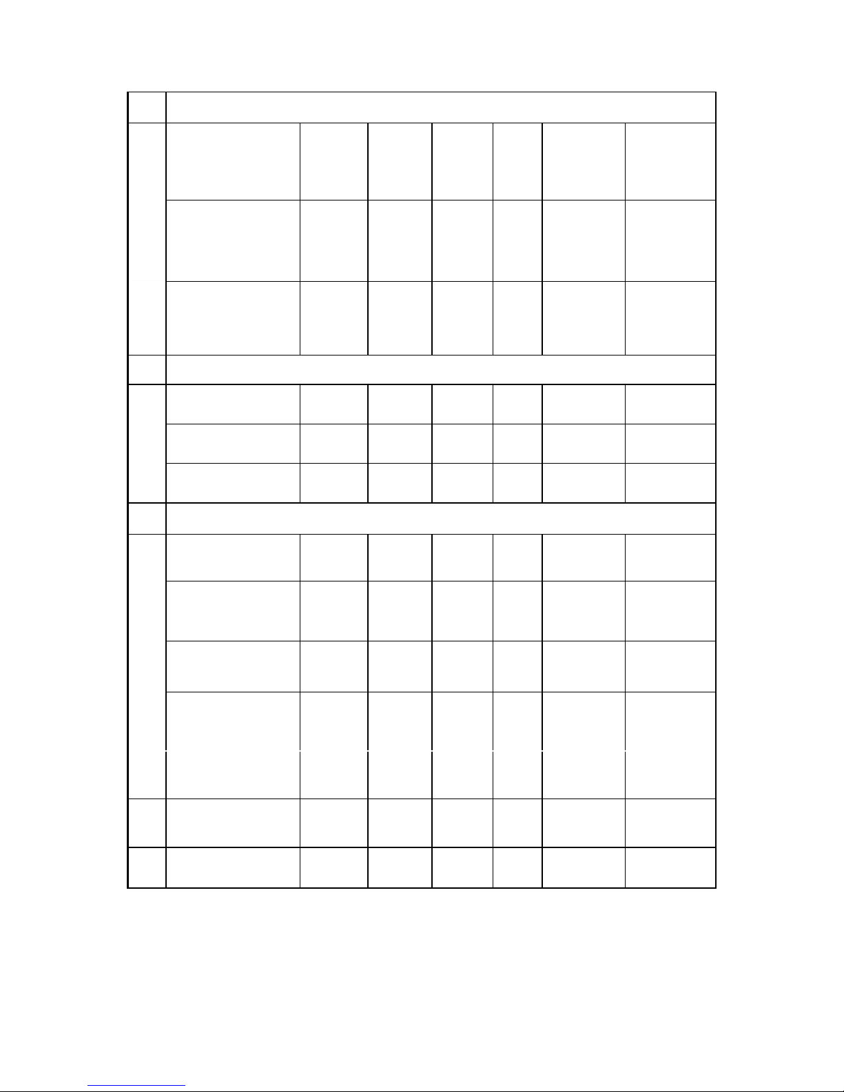
Normal
Battery
Bypass
Fault
1
Inverter mode (mains power)
Mains power
voltage
●
N
Mains power
high/low voltage
protection, switch
to battery mode
●
●
★
One beep /
4 sec
2 Battery mode
Battery voltage normal
● ●
★ One beep /
4 sec
Warning for
abnormal voltage
of battery
●
★
★
One beep /
sec
Page 30
30
3 Bypass mode
Mains power –
normal(under
Bypass)
●
★
One beep /
2 mins
Mains power – high
voltage warning
(under Bypass)
●
★
One beep /
4 sec
Mains power – low
voltage warning
(under Bypass)
●
★
One beep /
4 sec
4
Warning for battery disconnected
Bypass mode
●
★
One beep /
4 sec
Inverter mode
●
★
One beep /
4 sec
Power on / Switch
on
6 beeps
5
Output overload protection
Warning for mains
power overload
●
★
2 beeps /
sec
Protect operation
for mains power
mode overload
●
●
Long beep
Warning for
battery overload
●
●
★
2 beeps /
sec
Protect operation
for battery mode
overload
●
●
●
Long beep
6
Warning for bypass
mode overload
●
★
One beep /
2 sec
7
Fans fault(fan
icon)
▲
▲
▲
★
One beep /
2 sec
8 Faults mode
●
Long beep
Page 31

31
●
LED Indicator lights long time
★ LED Indicator flicker
▲ LED indicator status depends on other conditions
Note: Users need to provide below information when require to maintain the UPS.
UPS Model No. & Serial No.
Date of fault occurrence.
Fault detail (LED status, noise, AC power situation, load capacity, for long back up type,
battery capacity configuration is also necessary.)
Page 32
32
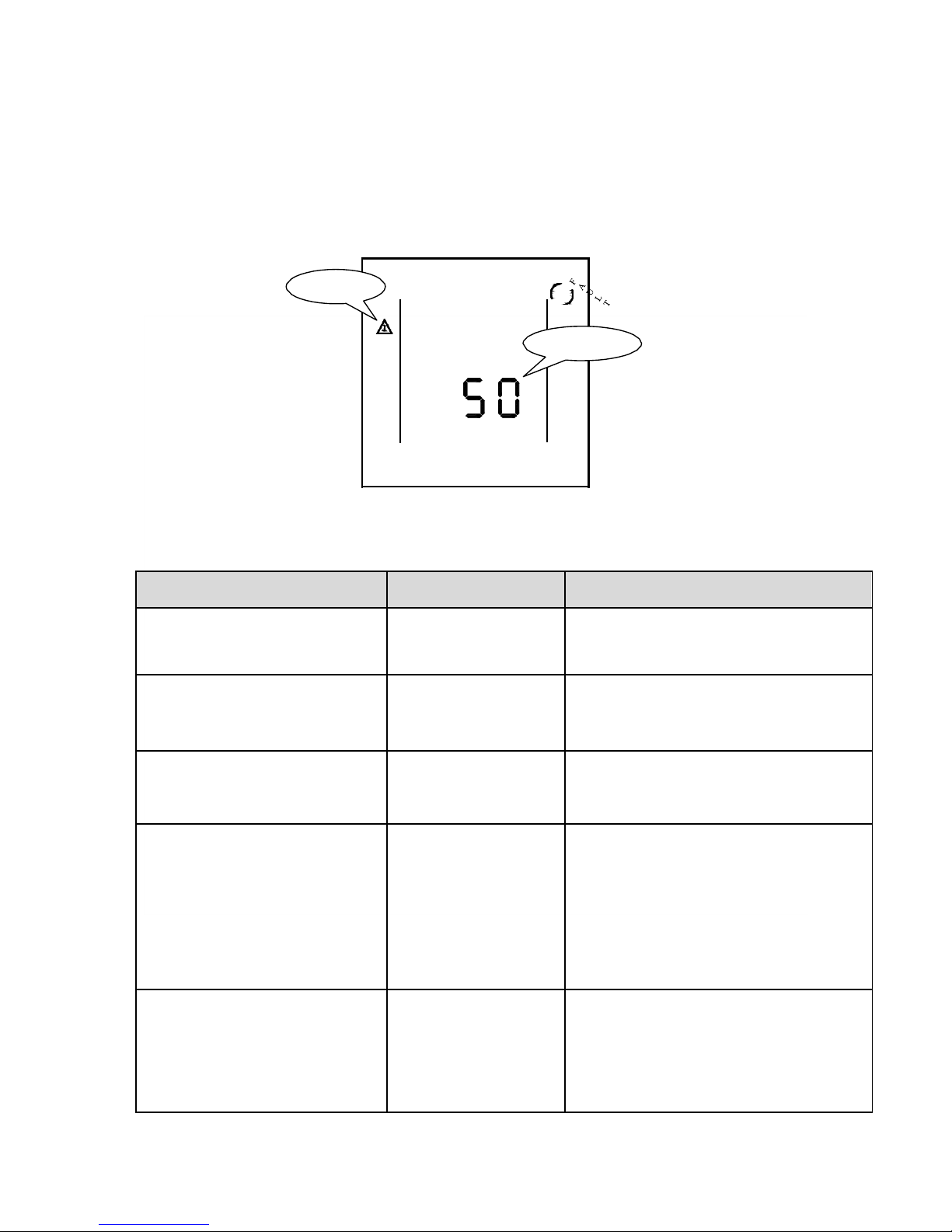
Fault icon
Fault code
Explicit Troubleshoot Introduction Sheet
6 TROUBLE SHOOTING
When the system runs in failure mode, the LCD will show as below:
Trouble indication
Failure point
Solution
Fault LED on, audible buzzer
Persistently alarm, the fault code
is 00-14
Bus bar voltage fault
Please test the bus bar voltage or contact
the supplier.
Fault LED on, audible buzzer
persistently alarm, the fault code
is15-24
Soft start fault
Please check the soft start up circuit,
especially the soft start resistance or
contact the supplier directly.
Fault LED on, audible buzzer
persistently alarm, the fault code
is 25-39
Inverter voltage fault
Please contact the supplier.
Fault LED on, audible buzzer
persistently alarm, the fault code
is 40-44
Over temperature
inside
Please make sure the UPS didn’t get
overload, and the fan vent was not
obstructed, as well as the indoor
temperature is not high.
Leave alone the UPS 10 minutes for
cooling, and restart it. If failure remains,
please contact the supplier.
Fault LED on, audible buzzer
Persistently alarm, the fault code
is 45-49
Output short-circuit
Turn off the UPS and disconnect all the
load, make sure there no any fault or
internal short circuit of the load.
And then restart the UPS, if failure still,
please contact the supplier.
Page 33

33
Fault LED on, audible buzzer
persistently alarm, the fault code
is 50-54
Over load
Please check the load level and disconnect
the noncritical devices, recount the total
capacity of your load and reduce the load
to the UPS.
Please check whether the load device has
fault or not?
Fault LED on, audible buzzer
persistently alarm, the fault code
is 55-59
Input NTC fault
Please contact the supplier.
Fault LED on, audible buzzer
persistently alarm, the fault code
is 60-64
Power fault
Please Check whether the input & output
power normal or not, contact the supplier
if it is abnormal.
Fault LED on, audible buzzer
persistently alarm, the fault code
is 65-69
Input fuse fault
Please check if the input fuse is burnt.
Replace the old fuse and restart the UPS.
If failure remains, please contact the
supplier.
Fault LED on, audible buzzer
Persistently alarm, fan icon in the
LCD flickers
Fan fault
Please check whether the fans connect
well, is the fan plugged and is the fan
broken? If all above condition is OK, please
contact the supplier.
UPS fail to start when operate
“On” key
Pressing time too short
Please press the power key more than 2
seconds to start the UPS.
The input connection is
not ready or
UPS internal battery
disconnect
Please connect the input well, if the battery
voltage is too low, please disconnect the
input and start the UPS with no-load.
UPS internal system
fault
Please contact the supplier.
Back up time become short
Battery undercharge
Please keep the UPS battery recharging
more than 3 hours.
UPS overload
Please check the load level and disconnect
the noncritical devices,
Battery maturing,
capacity descend
Please change new battery, contact your
supplier to get the new battery and spare
parts.
UPS doesn’t have any power go
through even main power on
UPS input breaker
disconnects
Please reset the circuit breaker by
manual.
ATTENTION: When the output is short-circuited, the action of the protection of the UPS will show
up. Before turning off the UPS, please make sure to disconnect the entire load and cut off the AC
mains power supply, otherwise will make the AC input short-circuit.
Page 34

34
7 ATTETTION BOF BATTERY DISPOSAL
Please take off your ring, watch and other metals before operate the batteries.
If you want to change the battery cable, please purchase the material from our local service
center or distributors, to avoid heating or spark due to the inadequate power capacity, and even
causing fire.
Don’t dispose of the battery or battery pack near or into fire, otherwise it will explode and
injure person.
Don’t damage or open the battery case, the battery electrolyte overflow is with highly toxic
which is harmful to human.
Please avoid short circuit between positive and negative terminal, otherwise may cause fire or
electric shock.
Please check the battery voltage before touching. If the loop of battery and loop of input
voltage is non-isolated, that will cause high voltage risk between battery terminals and ground.
8 NETWORK COMMUNICATION
This series UPS offer intelligent network interface with a dedicated Ethernet card (optional
accessory), realizing network communication and management. For more information about this
function, please turn to our local distributor or service center.
9 COMMUNICATION INTERFACE INTRODUCTION
The UPS communicates with PC via analog relay joint and serial interface (RS232). The former
transmits the input power and UPS status to PC by choosing “on” or “off” states of transistor. The
latter offers communication interface serials with PC to monitor input power and UPS status
information, and control the UPS also.
Page 35
35
Bit Pattern: None
Appendix 1: EMC Level
The series product is designed to meet the below standard.
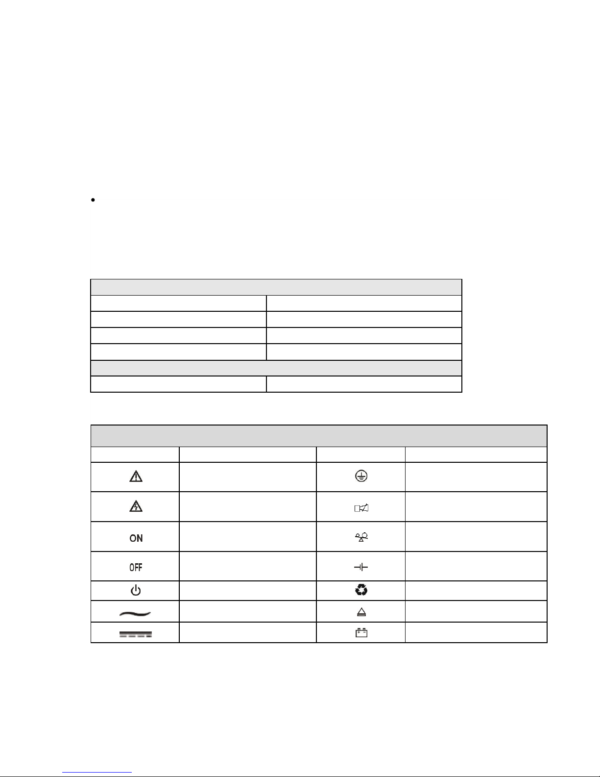
Appendix 2: Symbol instructions:
NOTE:
The communication function is only realizable with the specific communion cable from the
supplier.
Rs232 interface is set as below:
Bit rate: 2400bps
Byte: 8bit
Completion code: 1bit
EMS
IEC61000-4-2(ESD)
Level 4
IEC61000-4-3(RS)
Level 3
IEC61000-4-4(EFT)
Level 4
IEC61000-4-5(Suege)
Level 4
EMI
GB9254-1998/IEC 62040-2
Class B
Symbols and significations
Symbol
Significations
Symbol
Significations
Caution
Protect grounding
Danger! High Voltage!
Alarm cancel
Turn on
Overload
Turn off
Battery inspection
Standby or Shutdown
Repeat
AC
Display screen repeat key
DC
Battery
Page 36
36
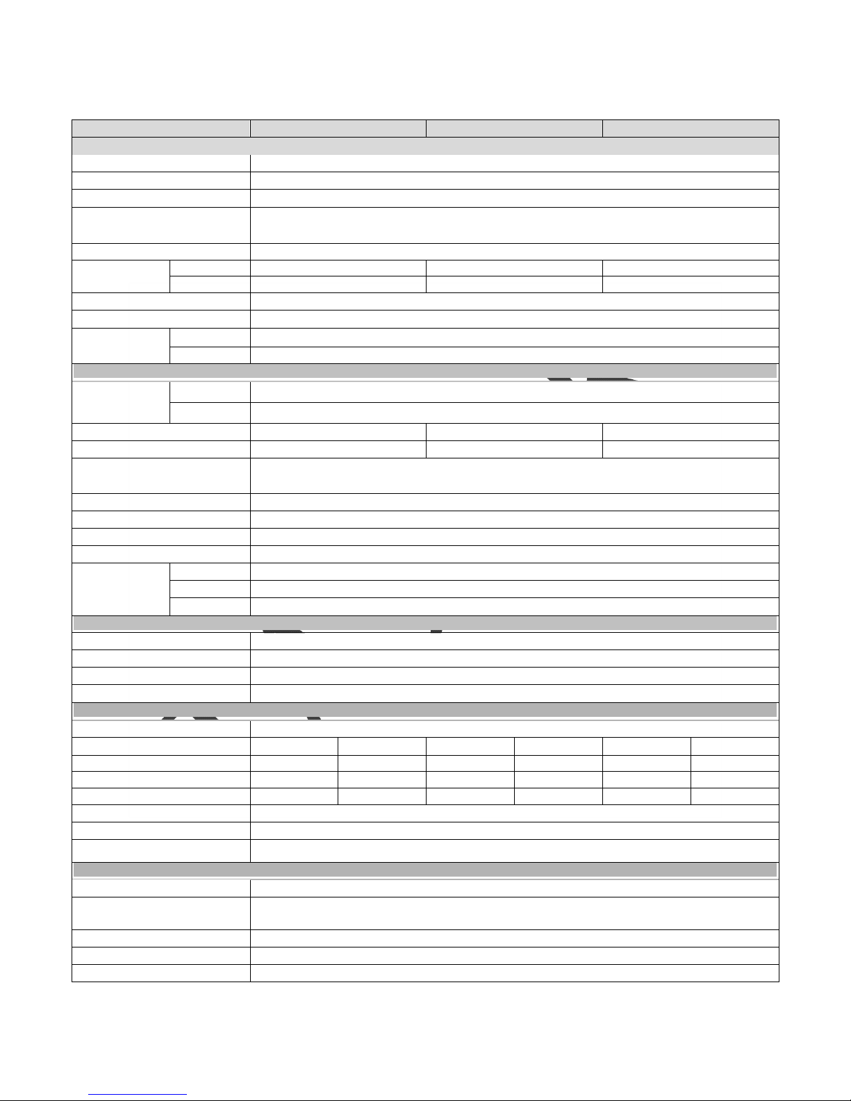
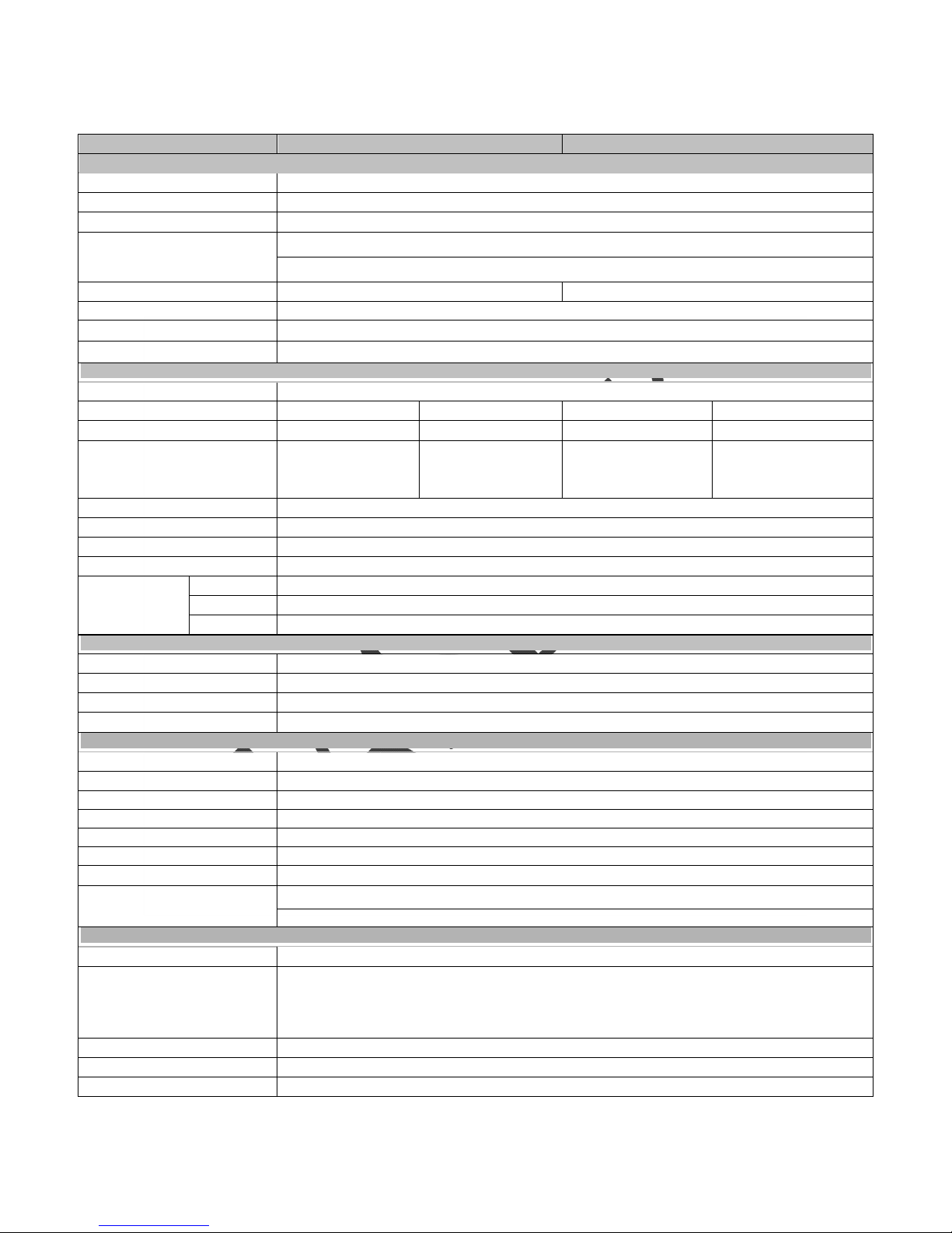
Appendix 3: Specification Sheet
Rated Capacity
1KVA
2KVA
3KVA
Input
Rated input voltage
220V or 120V
Rated input frequency
50Hz/60Hz auto-adaptive
Input voltage range (the type of 220V)
(115~295)±5VAC (half load) (145~295)±5VAC(full load)
Input voltage range
(the type of 120V)
(55~145) ±5VAC(60% LOAD); (65~145) ±5VAC(70% LOAD)
(75~145) ±5VAC(80% LOAD); (85~145) ±5VAC(100% LOAD)
Input frequency range
45-55Hz+/-0.5% 50Hz type 55-65Hz+/-0.5% 60Hz type
Input current
220V
8A max
15A max
23A max
120V
14A max
27A max
40A max
PFC
≥0.98
THDI
﹤
6%
Bypass voltage
range
220V
Rated output voltage -34V ~ Rated output voltage +32V
120V
(95~135) ±5VAC
Output
Output voltage
220V
208VAC /210VAC/220VAC/230VAC/240VAC Setting available
120V
100/110/115/120/127VAC Setting available
Output PF
0.8/0.9
0.8/0.9
0.8/0.9
Output power(Watt)
800/900
1600/1800
2400/2700
Inverter overload capability
105%~150%: transfer to bypass mode after 30s giving alarm;
>150% : transfer to bypass mode after 300ms giving alarm;
Voltage accuracy
±0.2
Load crest
3:1
From AC mode to BAT mode
0ms(transfer time)
From BAT mode to AC mode
0ms(transfer time)
Efficiency
LINE mode
≧90 % (full load)
BAT mode
87%
ECO mode
98%
Output frequency
Under Mains mode
Same as input frequency
Under battery mode
(50/60±0.2)Hz
Phase-locked rate
≤1Hz/s
Total voltage harmonic distortion
Full linear load< 3%;Full nonlinear load< 5%
Battery
Battery type
Sealed lead acid maintenance free battery
Quantity 2 3 4 6 6 8
DC voltage
24V
36V
48V
72V
72V
96V
Inbuilt battery
9AH/12V
7AH/12V
9AH/12V
7AH/12V
9AH/12V
7AH/12V
Output voltage
27.1±0.4V
40.6±0.5V
54.2±0.6V
81.3±0.9V
81.3±0.9V
108.4±1V
Back up time
Based on battery capacity
Charge method
Three-stage charging
Charge current
Standard model :1A Long time model: 6A
System Control and Communication
Function
Silence; cold start; AC restart; Auto restart.
Protection
Over-temp protection; Fan testing protection; AC L and N reversely connecting protection; Output short
circuit protection
Communication port
RS232; SNMP card; USB
Software function
Graphics analyze; Switch on/off UPS system; Monitor UPS working status; History record and event log
Display
LCD/LED
Page 37
37
Appendix 4: Specification Sheet (6-10KVA)
Rated Capacity
6KVA
10KVA
Input
Rated input voltage
220V
Rated input frequency
50Hz/60Hz auto-adaptive
Input voltage range
(115~295)±5VAC (half load); (145~295)±5VAC(full load)
Input frequency range
45-55Hz+/-0.5% 50Hz type
55-65Hz+/-0.5% 60Hz type
Input current
46A max
76A max
PFC
≥0.99
THDI
﹤
5%
Bypass voltage range
Rated output voltage -34V ~ Rated output voltage +32V
Output
Output voltage
208VAC /210VAC/220VAC/230VAC/240VAC Setting available
Output PF
0.8
0.9
0.8
0.9
Output power(Watt)
4800
5400
8000
9000
Inverter overload capability
105%~125%: 10 mins;
125%~150%: 30 secs;
>150%: 100ms;
105%~125%: 3 mins;
125%~150%: 30 secs;
>150%: 100ms;
105%~125%: 10 mins;
125%~150%: 30 secs;
>150%: 100ms;
105%~125%: 3 mins;
125%~150%: 30 secs;
>150%: 100ms;
Voltage accuracy
±0.2
Load crest
3:1
From AC mode to BAT mode
0ms(transfer time)
From BAT mode to AC mode
0ms(transfer time)
Efficiency
LINE mode
≧92% (full load)
BAT mode
90%
ECO mode
98%
Output frequency
Under Mains mode
Same as input frequency
Under battery mode
(50/60±0.2)Hz
Phase-locked rate
≤1Hz/s
Total voltage harmonic distortion
Full linear load< 3%;Full nonlinear load< 5%
Battery
Battery type
Sealed lead acid maintenance free battery
Quantity
16
DC voltage
192V
Output voltage
216.8±1V
Inbuilt battery
16*9AH/12V
Charge method
Three-stage charging
Back up time
Based on battery capacity
Charge current
Standard model:1A
Long time model: 1A /3A /5A /8A
System Control and Communication
Function
Silence; cold start; AC restart; Auto restart.
Protection
Over-temp protection;
Over-temp protection; Fan testing protection;
AC L and N reversely connecting protection;
Output short circuit protection
Communication port
RS232; SNMP card; USB
Software function
Graphics analyze; Switch on/off UPS system; Monitor UPS working status; History record and event log
Display
LCD/LED
Page 38
38
Communication port for PC
TCP/IP
This model UPS can supply one Intelligent Slot at the rear panel, which was compatible with
most of the software and hardware all of the world, such as running HP open view, IBM net view,
SUN net manager and other operation system. UPS is with function login on internet supplying
information of UPS status and input power, and even capable of controlling UPS via net
management system.
For more information, please turn to local supplier or distributor.
Appendix 5: Communication port
Communication port for PC
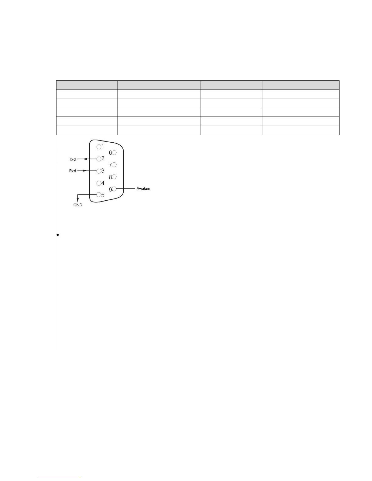
At the rear panel of this model, there is one DB9 port, which provides several signals as
follows:
Foot
Explanation
Foot
Explanation
1 empty
6 empty
2 Send
7 empty
3 receive
8 empty
4 empty
9 awaken
5 GND
Page 39

39
10 GUARANTEE
10.1 Terms of Guarantee
Our products are under a two-year guarantee starting from the date of delivery against
malfunctions resulting from production, material and workmanship faults. Malfunctions
due to such type of faults will be removed without claiming any price of workmanship or
spare parts to be replaced.
Whether aforementioned malfunctions originate from usage faults or not are determined
with a report to be issued by service stations, if there exists no service stations, by one of
seller, dealer, agency, representative, importer or manufacturer or producer of those
products respectively.
Repair time of defective products is twenty business days at most. This period starts from
the date when products are delivered to one of seller, dealer, agency, representative,
importer or one of manufacturer or producer. Provided that products break down within
the period of guarantee, the time passing during the repair process is added to the
guarantee time. Provided that faults of products cannot be removed within ten business
days, manufacturer-producer or importer is obliged to assign another product having
similar features for the use of consumers until the faulty product has been repaired.
Even though consumers exercise their repair rights, they can claim free replacement of
products, refund or price discount at the rate of faultin the events;
That, besides, the product,as of the date when the product is delivered to
the consumer, breaks down four times a year or six times within the
guarantee period to be determined by the manufacturer-producer and/or
importer at least, on the condition of being in guarantee period, such
malfunctions perpetuate passing over;
That maximum time required for the repair of products is exceeded;
That repair of the malfunction is determined as impossible through a
report to be issued by service station, if there exists no service station, one
of seller, dealer, agency, representative, importer or manufacturer or
producer of the company respectively.
The consumer is, on demand, obliged to submit guarantee certificate in terms of repairs
or replacements within the scope of guarantee.
It is essential that you definitely perform damage control over external packaging before
receiving the products to be sent through freight. In the event of any damage, delivery
person must be made to prepare a “damage determination record”. (For example;
duringthe delivery process, the product has been checked and seen that is damaged.)
Page 40

40
After the damage determination record has been issued, we request you to inform the
LEGA head office of the case. Products to be received from freight by signature means that
products have been received completely and without no damage.
Repairs of plug-and-play products in the places where no service point is around are
performed in the factory of LEGA or the nearest service point according to the direction to
be made by the LEGA head office. Defective product is delivered by hand to the nearest
service point or to the contracted freight company in its original packaging to be sent to
the factory of LEGA according to the direction to be made by the LEGA head office. For
malfunctions in the scope of guarantee, shipment fees are under the responsibility of LEGA
on the condition that products are delivered to the contracted freight company.
The device must be sent as packed in its original packaging as long as it is not desired by
the service. Original packaging of devices should be preserved in order to use them for
shipment of devices in terms of repairs to occur. Otherwise, no responsibility is assumed
with regards to any troubles to be experienced.
All defective products to be delivered by hand or through freight are to meet the necessary
shipment requirements. (Anti-static protective, bubble wrap or box etc.)It is essential that
legible barcode serial number belonging to the product be on the product. Otherwise, it is
not covered in the scope of the guarantee.
It is essential that products to be sent through freight definitely be together with delivery
note, and that serial/model/malfunction details be written on delivery note to be sent (for
example, breakdown report form), and that packaging content match with the products
specified in the delivery note. Otherwise, freight is not accepted.
The use of theGuarantee Certificate, submitted together with products with LEGA
trademark,is permitted by the T.R. Ministry of Industry and Commerce and General
Directorate of Protection of Competition with no……. in accordance with the law, with no.
4077, and the notification, with no. TRKGM-95/116-117, issued basing the
aforementioned law. LEGA acknowledges and undertakes to obey the liabilities
determined by the laws and legislations.
10.2 Cases Not Covered by the Guarantee
Breakdowns resulting from the use of products contrary to the issues or the environment
conditions (temperature, humidity etc.) specified in the user manual are not covered in
the scope of guarantee.
Damages and breakdowns resulting from the use of software, hardware, interface,
accessories or consumables apart from those used together with products or
recommended ones; changing place, wrong and insufficient maintenance, calibration or
use; its operation contrary to environment specifications published for products;
insufficiency of air installation; use of products in ambient having excessive humid or
temperature; its operation in environment harmful for electrical circuits and abrasive;
Page 41

41
and accidents, impacts, electric, shipment, natural disasters, not limited to the ones listed
above, are not covered in the scope of product guarantee.
In the general examination performed during the breakdown acceptance process, certain
troubles causing products not to be covered in the scope of guarantee might not be
understood. Provided that such faults come up in the detailed examination to be
performed via technical service equipment, products are returned to customers.
Products not covered in the scope of guarantee can, on demand of customer, be treated in
a fee-paying way within the bounds of possibilities of the authorized service. Products out
of the scope of guarantee, repairs of which are not possible are returned to customers.
Damages and breakdowns resulting from treatments, internally or externally tampering,
efforts to repair and spare part replacement of products, without approval of LEGA, and
those resulting from treatment of unauthorized service/dealer/person/establishment,
are not covered in the scope of guarantee. Breakdown, cracks, scratches and wear,
corrosion and dust to occur in time and by use in the outer surfaces of products (cabinet,
cover, and front panel) are not covered in the scope of guarantee.
In the event that original serial numbers, guarantee labels and stamps on products are
removed or distorted, products are not covered in the scope of guarantee. No guarantee is
issued against the use of products for any other purpose, apart from those specified in
introduction or manual of products.
Shelf lives of VRLA batteries are 6 months under the ambient temperature of 15 °C and 3
months under the ambient temperature of 25 °C.
It is compulsory that systems to be purchased be commissioned within 3 months.
Page 42

CUSTOMER
CERTIFICATE OF GUARANTEE
Certificate Approval Date : --/--/---Certificate No :
TITLE : LEGA ENERJI ELEKTRONIK SAN VE TIC LTD STI
ADDRESS : UMRANIYE ISTANBUL / TURKEY
TELEPHONE : 0216 – 533 09 03
FAX : 0216 – 533 15 61
SIGNATURE AND STAMP OF
COMPANY AUTHORITY
TYPE : _
TRADEMARK : _
MODEL : _
SERIAL NO / BANDEROLE : _
DELIVERY DATE AND PLACE : _
MAXIMUM REPAIR PERIOD : 20 business days
GUARANTEE PERIOD : _
TITLE : _
ADDRESS : _
TELEPHONE : _
FAX : _
INVOICE DATE / NO : _
DATE / SIGNATURE AND STAMP : _
TITLE / NAME : _
ADDRESS : _
SIGNATURE : _
42
OF THE PRODUCT
VENDOR
MANUFACTURER COMPANY
Page 43

CERTIFICATE OF GUARANTEE
1 – Guarantee period starts from the delivery date of the product and lasts………..years.
2 – The whole product, including all its parts are under the guarantee of our company.
3 – Provided that the product breaks down within the period of guarantee, the time passing during
the repair process is added to the guarantee time. Repair time of the product is ……. business days
at most. This period starts from the date when the malfunction related to the product is informed
to the service station, if there exists no service station, to one of seller, dealer, agency,
representative, importer or one of manufacturer. Provided that the fault of industrial product
cannot be removed within 10 business days, manufacturer or importer is obliged to assign another
industrial product having similar features for the use of the consumer until the faulty product has
been repaired.
4 – Provided that the product breaks down due to materials and workmanship or assembly faults
within the period of guarantee, the product is repaired without claiming any charge for
workmanship, any price for spare part replacement or any fee under any name.
5 – The product will be replaced without any charge in the events;
- That passing over the product perpetuates due to the fact that the product repeats the
same malfunction more than twice or different malfunctions occur more than four times
in a year starting from the delivery date, on the condition of being in guarantee period;
- That maximum time required for the repairment of the product is exceeded;
- That, if there exists no service station, the repair of the malfunction is determined as
impossible through a report to be issued one of seller, dealer, agency, representative,
importer or manufacturer of the product respectively.
6 - Malfunctions resulting from the use of the product contrary to the issues specified in the user
manual of the product are not covered in the scope of guarantee.
7 –For any trouble that may come up in terms of the Certificate of Guarantee, the Ministry of
Industry and Commerce, General Directorate of Protection of Consumer and Competition can be
applied.
NOTICE
8 – Under no circumstances shall the customer treat the product with the aim of repair, apart
from LEGA authorized service personnel.
9 – Damages and results originating from the violation of the 8
th
Article shall be invoiced to the
customer.
The use of herein the certificate is permitted by the T.R. Ministry of Industry and
Commerce and General Directorate of Protection of Consumers and Competition in
accrordance with the Law on the Protection of Consumers, with no. 4077, and the
Notification Concerning the Application Principles of Guarantee Certificate, issued basing
the aforementioned law.
Page 44

 Loading...