

Page 1
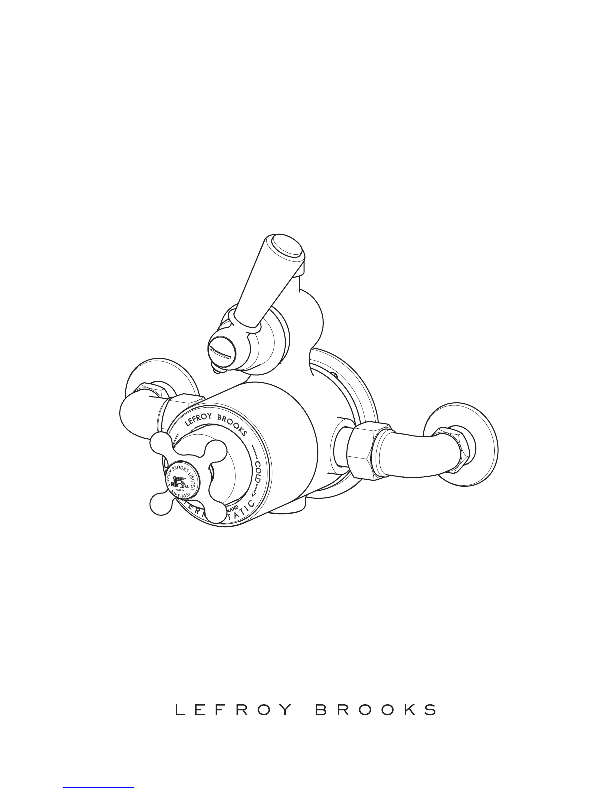
CT 8700 / MK 8700
EXPOSED THERMOSTATIC SHOWER VALVE
WITH CERAMIC LEVER
INSTALLATION GUIDE
Page 2
T
H
E
R
M
O
S
T
A
T
I
C
L
E
F
R
O
Y
B
R
O
O
K
S
M
A
D
E
I
N
E
N
G
L
A
N
D
H
O
T
C
O
L
D
MADE IN
L
E
F
R
O
Y
B
R
O
O
K
S
L
I
M
I
T
E
D
E
N
G
L
A
N
D
50mm
105mm
33mm
107mm
Ø90mm
15mm Copper
153mm (Connaught – CT)
148mm (Mackintosh – MK)
COLDHOT
200mm
G¾
2
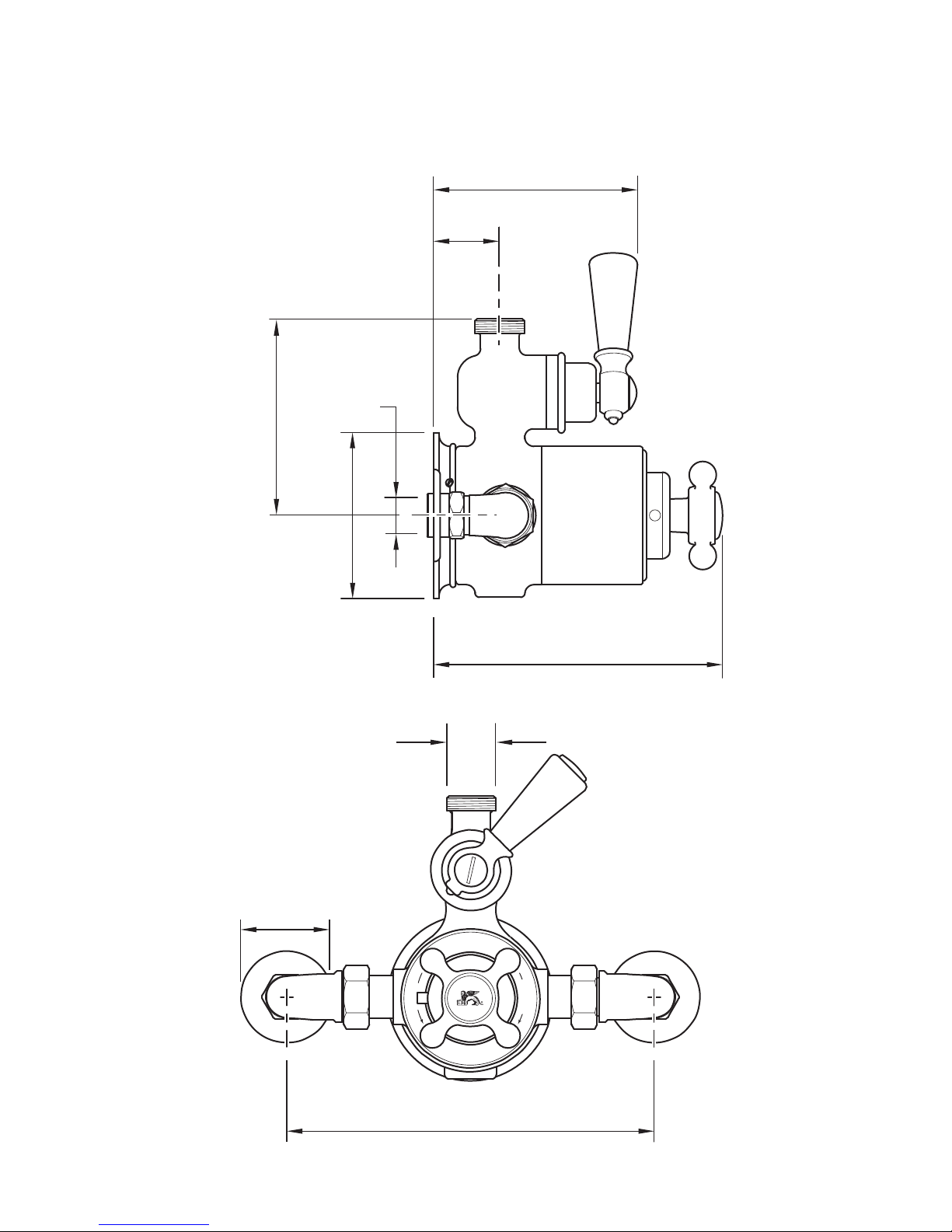
DIMENSIONS
Not to scale
Shown with CT8700
Page 3
200mm
1035mm
maximum
200mm
585mm
585mm
1085mm
maximum
CT/MK 8702
CT/MK 8720
CT/MK 8703
CT/MK 8705
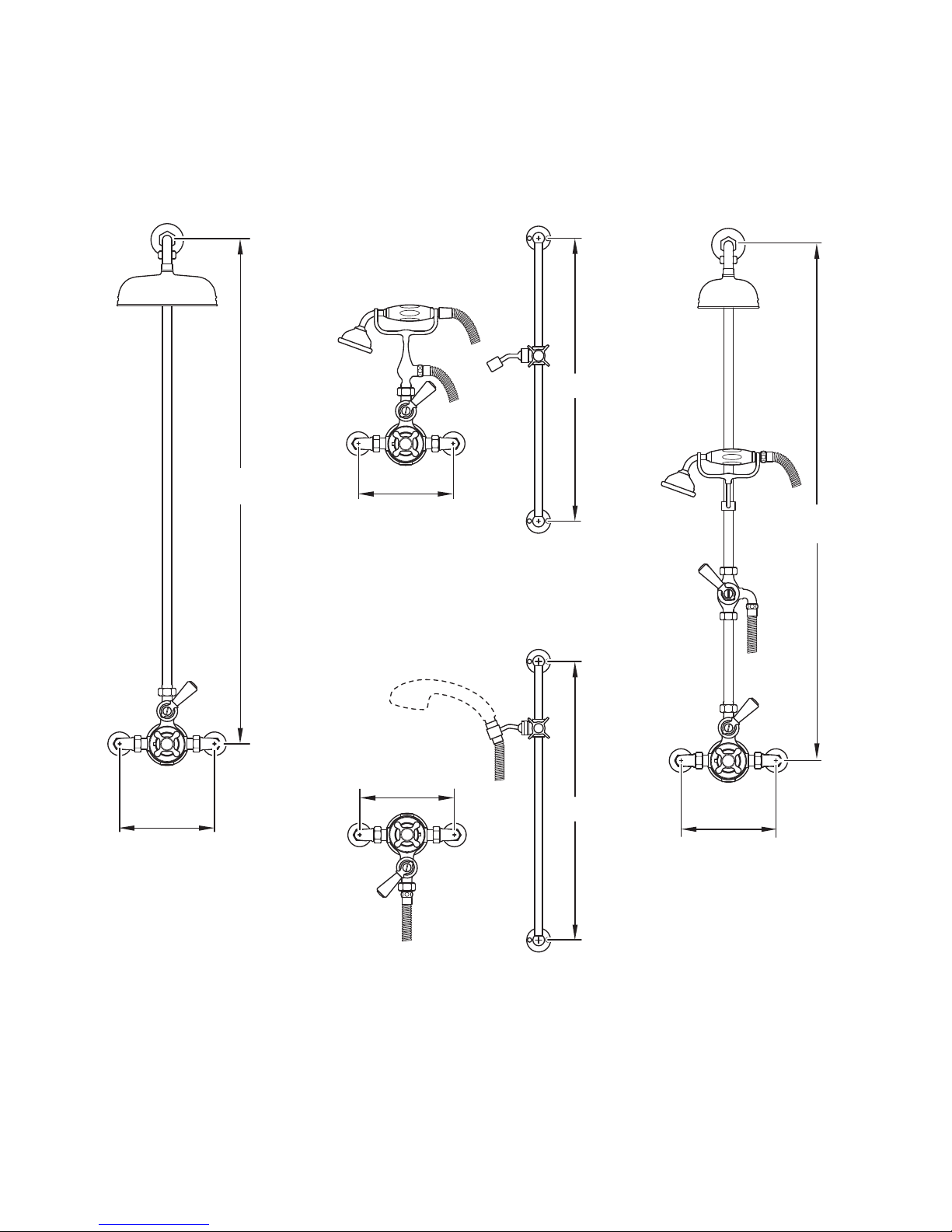
All dimensions are taken from centres
HOTCOLD
HOT COLD
200mm
200mm
(Note: On 8720 the hot is on the right and cold on the left)
HOT COLD
HOT COLD
3
TYPICAL SHOWER SETS
Not to scale
Page 4
4
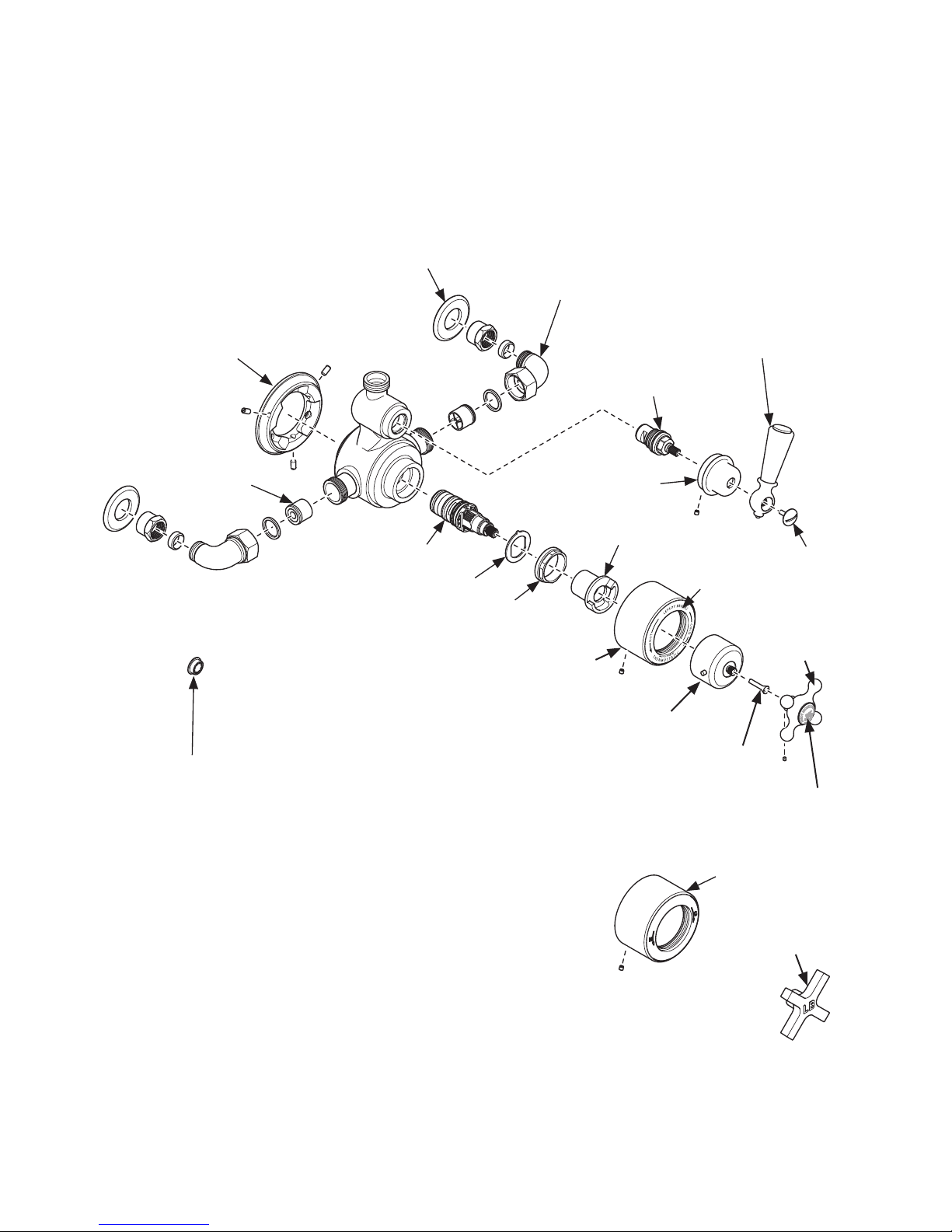
EXPLODED VIEW
PTE005 –
Valve backplate
Flow supressor (white)
See ‘balancing flow’ in ‘important
information’ section
PTS002 –
Non-return
valves (pair)
PTS024 – Override
including screw
PTS026 – (CT)
Handwheel
with lion indice
PPW005 – Lion indice
only
PTS011 – Ceramic
ring only
PTS030 – Screw
PTE018 – (CT)
Thermostatic
cartridge cover
PTE020 – (MK)
Thermostatic
cartridge cover
PTS025 – (MK)
Handwheel
PTS020 – Lock washer
PTS022 – Temperature stop
LB2750 – Thermostatic cartridge
PTS021 – Lock nut
PTS007 – Screw
PTS004 – White lever (UPPER ceramic only)
PTE016 – Black lever (ceramic only)
PTE002 – Flow cartridge
PTE003 – Flow control
cover
PTE007 – Pair of 15mm crack cover plates
PTE040 – A single 15mm crack cover plate
PTE006 – Pair of 15mm inlet connection elbows
with compression nuts, olives and fibre washers
PTE041 – A single 15mm inlet connection elbow
with compression nut, olive and fibre washer
Page 5

10
20 30
40
3.0
2.0
1.0
50
Flow (Litres/minute)
Static Pressure (Bar)
5
TYPICAL FLOW RATES
Note: Balanced pressures shown are applied directly to the hot and cold inlets; flow rates indicated are
free flowing and may var y subject to restrictions created by installation, pipework, layout or application.
The outlet temperature during testing was 38°C.
Page 6

6
IMPORTANT INFORMATION
Professional installation
We recommend that our products are fitted
by a fully qualified professional plumber. They
should be installed correctly and in accordance
with all local water regulations. All products and
connections should be accessible for routine
servicing.
Suits all systems
This Lefroy Brooks product is potentially
suitable for every possible application, type of
boiler and water supply pressure. However, for
full ‘power’ shower performance it is advisable
to fit a water pump if the supply pressure is
below 1 bar. For systems with combination
boilers, it is not advisable to fit pumps (refer
to boiler manufacturer).
Recommended supply temperatures
HOT = 60/65°C
COLD = 10/15°C
Water quality
In hard water areas, a suitable water treatment
system should be provided to prevent limescale
deposits (calcium deposits) which may eect
the long term performance of the thermostatic
cartridge and ceramic cartridge. Exterior
surfaces should be gently wiped with a dry soft
cloth after use to minimise water stains and
limescale deposits.
Servicing
All serviceable parts are available to maintain
your Lefroy Brooks product. We recommend
periodic servicing to help maintain the best
performance from your shower (‘servicing the
thermostatic cartridge’, ‘replacing the flow
cartridge’ & ‘replacing the non-return valve’
sections). Time between servicing can vary as it
is subject to usage and water quality. Servicing
kits are available (reference code PTE021) or
refer to exploded view for individual items.
Flushing system
It is most important to flush out all pipework
thoroughly before connecting the product.
This is the single most common cause of ceramic
cartridge and thermostatic cartridge failure.
Supply connections
The hot water supply must be connected to the
left inlet elbow and cold water supply to the
right inlet elbow, as viewed from the front. If the
thermostatic valve is fitted with the flow valve
at the bottom the hot water supply must be
connected to the right inlet elbow and the cold
water supply to the left inlet elbow.
Balancing flow
If there is a significant dierence in water
pressures between hot & cold supplies, we
recommend an in-line flow suppressor/
regulator (supplied) be fitted.
Safety/Anti-scald
This thermostatic valve not only maintains a
constant temperature to approximately plus
or minus 1°C, but will automatically shut down
completely on failure of hot or cold supplies.
Temperature setting
Once the installation has been completed the
‘safe temperature’ must be checked and set
in accordance with the setting instructions
(see following ‘setting safe temperature’ &
‘fitting the temperature override’ sections).
The valve is factory set but the working
temperature may dier subject to the hot & cold
water temperatures being supplied to the valve.
Page 7

7
Fixing the valve backplate to a wall
When locating and securing the valve backplate
(see exploded view) to a wall, it is important
to use No. 8 screws. Before marking mounting
hole locations, ensure that one of the set screws
mounted in the valve backplate is at the bottom.
Non-return valves
To protect your water system, non-return
valves are fitted inside the inlet elbows to the
sides of the valve body. These can be removed
and cleaned if required.
Testing
It is important to pressure check all
connections. During manufacture the internal
components and external joints of the valve are
pressure tested to 5 bar. However, installation
can aect the external joints. For this reason we
recommend that all connections to and from the
valve are pressure tested.
Access
It is important to leave suitable clearance and
access to the valve and connections for future
servicing.
Setting the ‘safe temperature’
To avoid damage, when setting the ‘safe
temperature’ the thermostatic cartridge spindle
must be turned by hand only. The spindle will
require only minor adjustment. Turning the
spindle to the end of its travel and forcing it
beyond this point will cause internal damage to
the thermostatic cartridge.
Always fit the black plastic ‘temperature stop’
before fitting the ‘override’. One of the
functions of the temperature stop is to prevent
the thermostatic cartridge spindle being turned
beyond the end of its travel. Not fitting the
temperature stop will result in damage to the
thermostatic cartridge.
Page 8
8
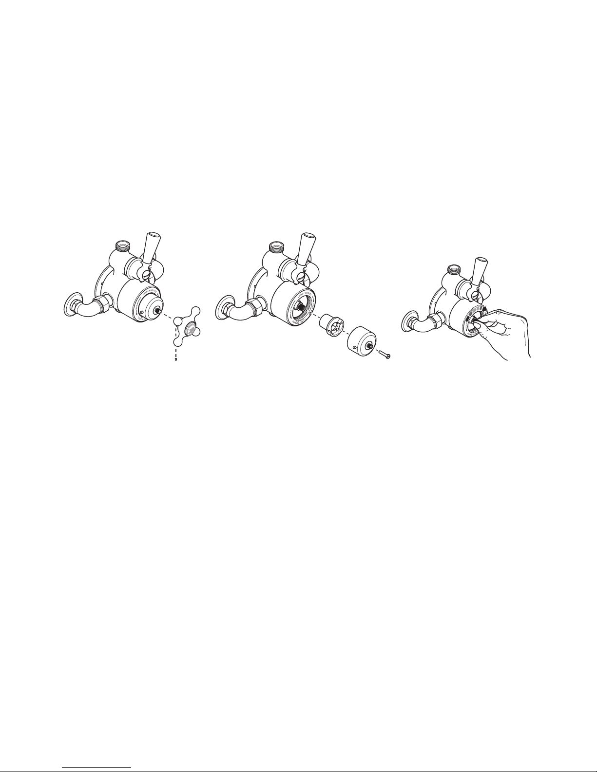
SETTING ‘SAFE TEMPERATURE’
Recommended safe temperature settings:
General domestic: 38 °C Young children or elderly: 37 °C
For specific details please refer to local building regulations, current legislation,
relevant standards and codes of practice.
This valve is designed to be set at the required safe operating temperature, but is fitted with an override
button which allows the user to select higher temperatures if required. The override control is to be
returned to the ‘safe temperature’ setting after use.
Remove the thermostatic
control handwheel (A) by
unscrewing set screw (B) using
a 1.5mm hexagonal key.
Remove the override (C)
and temperature stop (D)
by unscrewing and removing
screw (E). Fitting handwheel
(A) and set screw (B) will aid
with removal of override (C).
Adjust the car tridge spline
whilst measuring the
temperature of the water.
Ideally the temperature
measurement should be taken
using a digital thermometer.
Duty of care
Legislation dictates recommendations and guidelines on health and safety, including safe hot water
temperatures. The emphasis is on regulatory and design criteria, with responsibility for meeting such
guidelines being that of a suitably appointed responsible person.
How hot water temperatures aect the skin
65°C A partial thickness burn in about 2 seconds
60°C A partial thickness burn in about 5 seconds
55°C A partial thickness burn in about 15 seconds
50°C A partial thickness burn in about 90 seconds
Safe temperature
The age, mental and physical capabilities of persons occupying the proper ty will eect the ‘safe
temperature’ setting of the thermostatic valve. For specific details please refer to local building
regulations, current legislation, relevant standards and codes of practice.
A
B
D
C
E
Page 9
D
C
Button position
Set horizontal –
or slightly lower
Minimum
temperature
Maximum
temperature
Safe temperature
(see ‘setting safe
temperature’ section)
(button alignment)
Safe temperature locator
Safe temperature position
E
9
Temperature stop (D) orientation
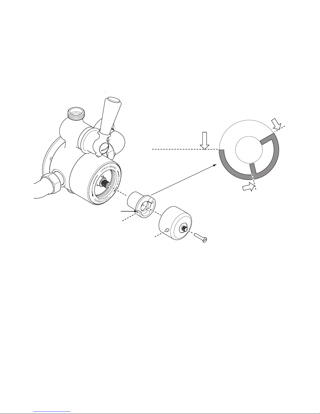
Once the safe operating temperature has been set, the next stage is to correctly assemble the
temperature stop (D) & override (C). The temperature stop and ‘safe temperature’ button can be
positioned to customer requirements. The below setting is suitable for right handed operation.
Three typical settings are shown on the next page.
FITTING THE ‘TEMPERATURE OVERRIDE’
1 Locate the temperature stop (D) onto the
cartridge spline with the ‘safe temperature’
locator in a horizontal or slightly lower position.
This is dependent on the orientation of the
splines (as shown above). Do not set higher as
this will eect the position of the button on the
override (C). Once located in a suitable position
push the temperature stop in fully.
2 Locate the override (C) with the button
positioned horizontally and to the left. Slide the
override carefully onto the smaller cartridge
spline. There may be a small amount of rotation
required to align the override mechanism with
the safe temperature position.
Note: The button may not be per fectly
horizontal depending on the orientation of the
cartridge splines.
3 Secure with screw (E). It is impor tant to check
the water temperature.
4 Fit the temperature control handwheel (A) then
tighten set screw (B) using a 1.5mm hexagonal
key to secure.
Page 10
MADE IN
L
E
F
R
O
Y
B
R
O
O
K
S
L
I
M
I
T
E
D
E
N
G
L
A
N
D
MADE IN
L
E
F
R
O
Y
B
R
O
O
K
S
L
I
M
I
T
E
D
E
N
G
L
A
N
D
MADE IN
L
E
F
R
O
Y
B
R
O
O
K
S
L
I
M
I
T
E
D
E
N
G
L
A
N
D
Safe temperature
(see ‘setting safe
temperature’ section)
Temperature stop positionButton position
Set vertically –
or slightly
counter clockwise
Minimum
temperature
Maximum
temperature
Set horizontal –
or slightly lower
Minimum
temperature
Maximum
temperature
Set horizontal –
or slightly
higher
Minimum
temperature
Maximum
temperature
(button alignment)
(button alignment)
(button alignment)
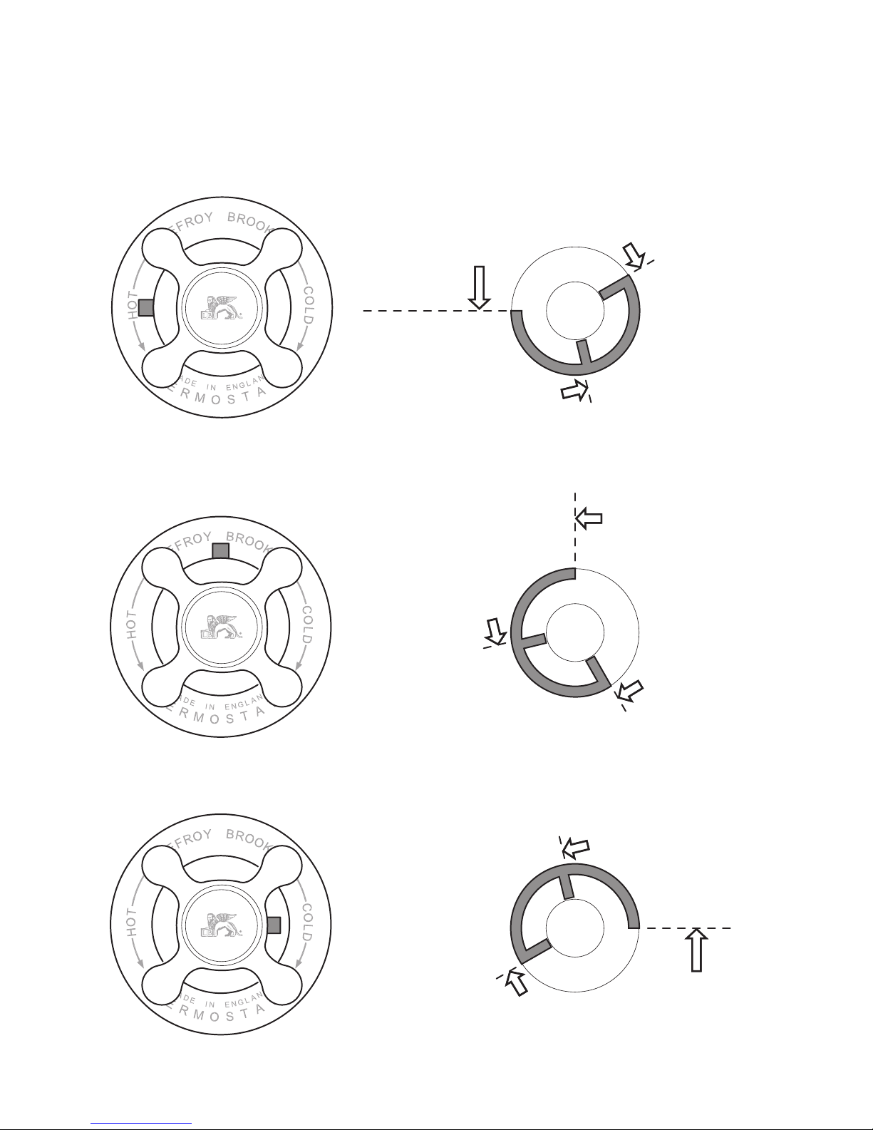
Safe temperature button set to top
(suitable for right and left handed operation)
Safe temperature button set to left
(suitable for right handed operation)
Safe temperature button set to right
(suitable for left handed operation)
Safe temperature
(see ‘setting safe
temperature’ section)
Safe temperature
(see ‘setting safe
temperature’ section)
10
The temperature stop and safe temperature button can be positioned to customer requirements
as below:
Page 11
11
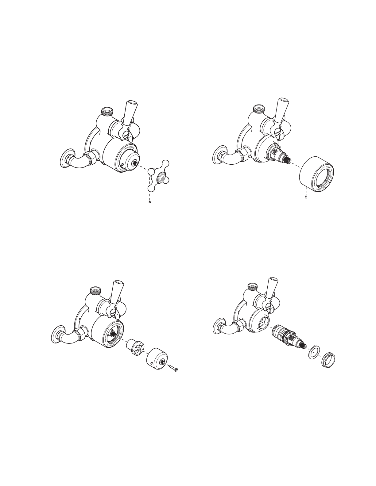
3 To remove the thermostatic cartridge cover
(F) unscrew the set screw (G) using a 1.5mm
hexagonal key and pull the thermostatic
cartridge cover away from the valve body.
4 To remove the thermostatic cartridge
(H), unscrew and remove locking nut (J).
Remove anti-rotation washer (K) and pull out
cartridge. To help with cartridge removal, it is
recommended you fit override (C) with screw
(E) to make pulling the cartridge out easier.
1 Isolate the hot and cold water supplies before
the shower valve. Remove the thermostatic
control handwheel (A) by unscrewing set
screw (B) using a 1.5mm hexagonal key.
2 Remove the override (C) and temperature
stop (D) by unscrewing and removing screw
(E). Fitting handwheel (A) and set screw (B)
will aid with removal of override (C).
SERVICING THE THERMOSTATIC CARTRIDGE
F
G
H
J
K
A
B
E
C
D
If after a period of time you experience temperature problems with your shower valve,
particularly if you are in a hard water area, it is quite common for limescale deposits to have formed
in the thermostatic cartridge. We recommend you remove the car tridge and soak it in a descaling fluid
which normally resolves the problem. It is dicult to set a regular servicing time scale as it is subject to
water conditions and usage.
Page 12
12
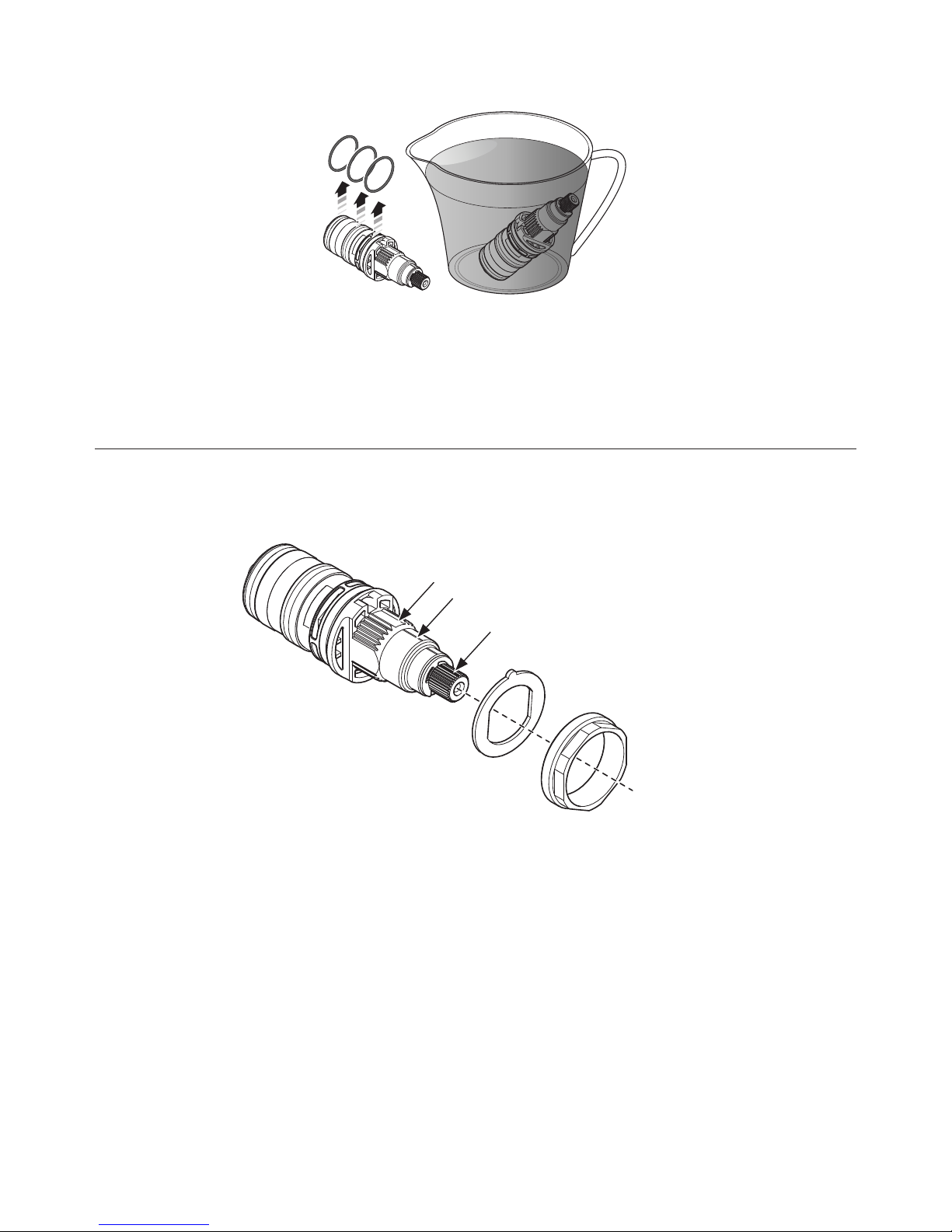
5 Check the ‘o’ rings (L) for damage (ie. cuts or tears). Remove the ‘o’ rings before soaking the cartridge
in descaling fluid. Soak the car tridge according to the instructions on the descaling fluid packaging. Rinse
under cold water before fitting (refer to the ‘installing the thermostatic cartridge’ section to install).
L
INSTALLING THERMOSTATIC CARTRIDGE
Important note:
For an approximately 38 °C setting, align the
‘key setting points’ shown. Once assembled,
reset the safe temperature by following
the setting instruction in the ‘setting safe
temperature’ section. Check the water
temperature with a thermometer.
1 Once the ‘key setting points’ have been
aligned and ‘o’ rings (L) fitted, apply a smear of
silicon grease to the ‘o’ rings and firmly push
the thermostatic cartridge (LB2750) into the
valve body with the groove pointing upwards.
2 Insert the anti-rotation washer (K) so it
locates to the ‘flats’ on the cartridge and fits
into the ‘notch’ cut into the valve body.
3 Screw in locking nut (J) and fully tighten using a
32mm a/f spanner to secure the thermostatic
cartridge in place.
Groove
Black line or drilled indication hole
LB2750
K
J
Slot
Page 13
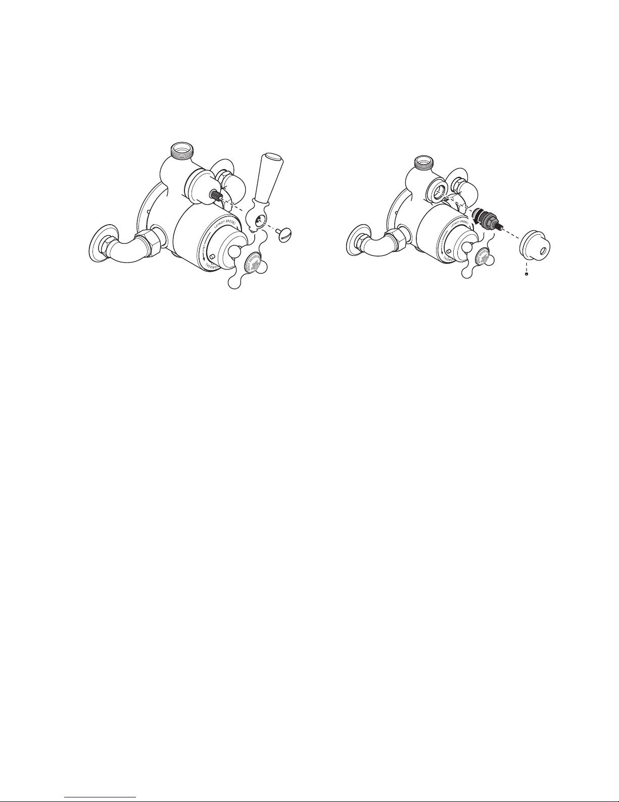
If after a period of time you experience problems with your shower or hand shower developing a regular
drip after use, it is normally an indication that the flow cartridge requires replacement.
13
REPLACING THE FLOW CARTRIDGE
(PTE002)
1 Remove the lever assembly (M) by fully
unscrewing and removing the fulcrum screw
(N) in a counterclockwise direction. Gently
pull the lever from the cartridge spline.
2 Remove the cartridge cover (P) by unscrewing
set screw (Q) using a 1.5mm hexagonal key.
We recommend wearing a rubber glove such
as those used for washing up to improve grip.
3 Using a 17mm spanner or socket, unscrew
the flow cartridge (R) (counterclockwise) and
remove. The replacement cartridge code is
PTE002.
4 After installing the replacement flow cartridge,
fit the cartridge cover and lever in reverse
order.
M
N
Q
R
P
Page 14
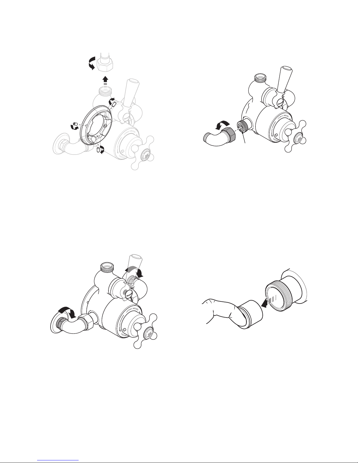
Non-return
valve (NRV)
14
1 Isolate the hot and cold water supplies before
the shower valve. Unscrew and remove the
hose/pipe connected to the flow valve outlet.
Unscrew the three set screws from the valve
backplate.
2 Support the thermostatic valve. Unscrew
the two collar nuts in a counterclockwise
direction. This will release the thermostatic
valve from the mounting surface.
3 Unscrew the elbow assemblies from the sides
of the thermostatic valve body.
4 Place a finger into the end of the non-return
valve and pull the non-return valve out of the
va lve b ody.
5 Assemble in reverse order using replacement
non-return valve(s).
REPLACING THE NON-RETURN VALVES
Page 15

15
DOs DON’ Ts
• Check all joints and connections.
• Ensure that the ‘safe temperature’ has been set.
• Ensure the black plastic ‘temperature stop’ has
been fitted to avoid damage to the thermostatic
cartridge and enable the ‘safe temperature’ to
be operational.
• Ensure that the thermostatic valve, connected
controls and outlets work satisfactory.
• Instruct the customer how to override the ‘safe
temperature’ setting. Also ensure the customer
knows the dangers of overriding the setting and
understands that the override control is to be
returned to the ‘safe temperature’ setting after
use.
• Hand these instructions along with the cleaning
leaflet to the customer.
• Ensure that the valve is suitably protected
from damage and decorating materials during
installation.
• Do not use excessive force when turning
the thermostatic cartridge spindle. This will
damage the cartridge. To avoid damage, when
setting the ‘safe temperature’ the thermostatic
cartridge spindle must be turned by hand only.
The spindle will require only minor adjustment.
Turning the spindle to the end of its travel and
forcing it beyond this point will cause internal
damage to the thermostatic cartridge.
Page 16

Whilst every effor t is made to ensure the accuracy of these, they are subject to change without
notice as part of the company’s product developme nt process. The use of trademarks, product design
and art work is subject to licence or agreement with LBIP Ltd. The design registrations, trademark registr ations
and copyrights are protected by law and t he use or reproduction outside the terms of an agreeme nt is prohibited.
The right to modify designs and dimensions is reserved. LBIP Ltd is a member of ACID (Anti Copying in Design).
© LBIP Ltd 2017
CUSTOMER SUPPORT
+44 (0)1992 708 316
LEFROYBROOKS.CO.UK
20.065.272A / JUNE 2017
 Loading...