

Page 1
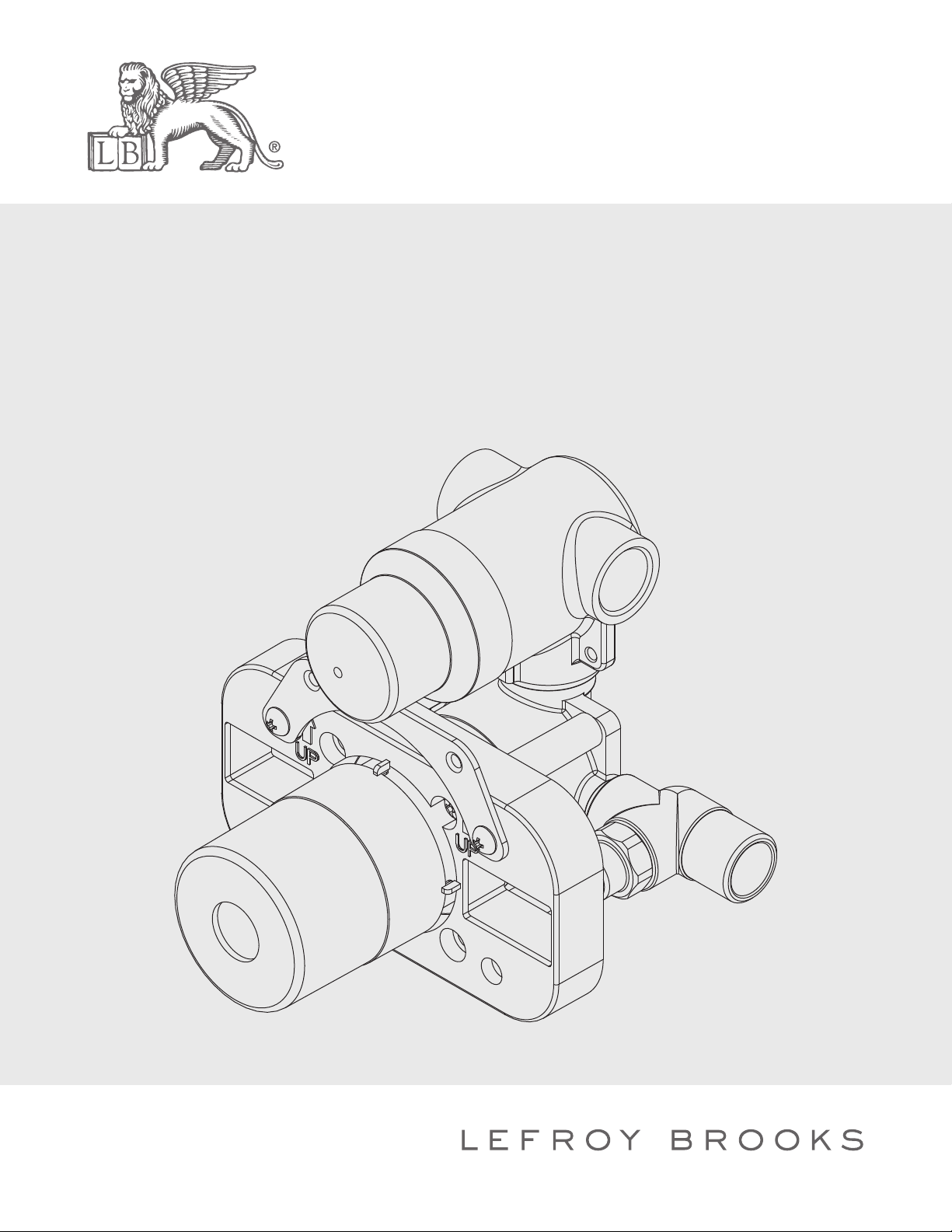
INSTALLATION INSTRUCTIONS
M1-4101
TWO HANDLE PRESSURE BALANCE ROUGH WITH 2-WAY DIVERTER, TO
SUIT M1-4302, M1-4303, X1-2000 & X1-2001, CW-4055 & CB-4065
Page 2
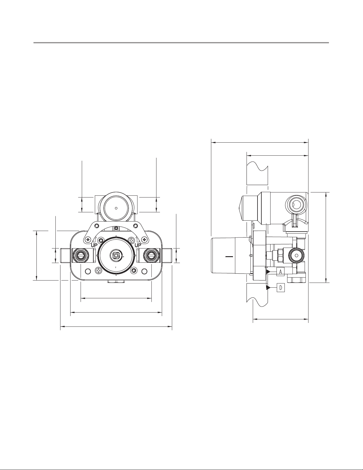
Dimensions
M1-4102
in Inches (& Millimetres)
5 3/8"
(137mm)
3 1/16"~4 1/16"
(78~103mm)
2 3/4"
(70mm)
1/2"-14NPT
1/2"-14NPT
3 15/16"
(100mm)
5 1/8"
(130mm)
6 1/4"
(158mm)
1/2"-14NPT
1/2"-14NPT
3 1/16"
(78mm)
(160mm)
6 5/16"
Whilst every effort is made to ensure accuracy, design and dimensions are subject to
change without notice as part of the company’s product development process.
2
Page 3
What you need to know
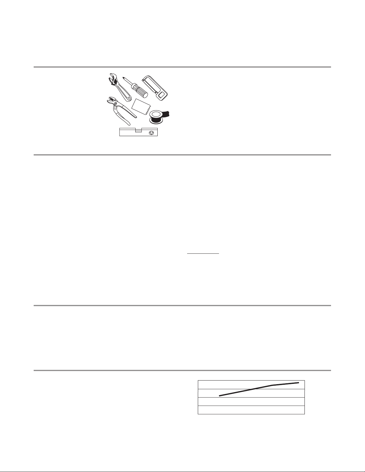
Tools: Maintenance
Adjustable Wrench
Groove Joint Pliers
Hacksaw
Phillips Screwdriver
Pipe Tape
Spatula
Spirit Level
Safety Tips
If you are soldering during faucet installation,
remove cartridges, seats, gaskets and washers
prior to applying flame, otherwise you will void
the warranty.
Cover drain openings to avoid losing small parts.
When cutting or soldering pipe, use safety glasses
to protect your eyes.
Your new bathroom faucet is designed for years
of trouble-free performance.
Keep it looking new by cleaning it periodically with
a soft cloth. Avoid abrasive cleaners, wire wool and
harsh chemicals as these will dull the finish and
void your warranty.
Important Points
Prior to beginning installation. turn off the cold and
hot water lines and open the old faucet to release
built-up pressure.
Overtightening nuts may cause damage.
Wrap all threaded connections with pipe tape
available at your local plumbing supply store.
Always wrap in a clockwise direction. The fittings
should be installed by a state-licenced plumber.
Please note:
When there is a difference in water pressure between
hot and cold supplies to the mixing valve, the pressures
should by equalized by a plumber in accordance with
best practice and legislation.
Things You May Need
Correct installation may vary depending on previous faucet installation. All necessary supplies required for
faucet installation are not included, but may be found where plumbing supplies are sold. It is suggested that
IAPMO and/or CSA approved plumbing supplies are used during installation.
Standards
Standards Flow Rate
IAPMO/cUPC Listed
Meets A112.18.1
Meets ASSE 1016
7
3
0
20 40 60 80PSI
Please note :
Final achievable flow rate is dependent on the outlets fitted, see relevant outlets (spouts, roses, sprays) for fully
assembled product flow rate.
3
Page 4
Steps 1-6
Installation Procedure
Lefroy Brooks always recommends that plumbing products be installed by a licensed professional.
Shut off main water supply before installation.
84mm~109mm
DO NOT REMOVE "PLUG"
Stopper A (marked #049000)
Stopper B (marked #049001)
Washer C
mixed water out #1
HOT WATER - IN
1 2
Dimple on valve stem
mixed water out #2
COLD WATER - IN
REMOVE CAP ONLY, KEEP THE REST OF THE
MUD GUARD AS IT IS NEEDED TO HOLD THE
TRIM FIXING SCREWS.
Notch
3
1
2
3
4
4
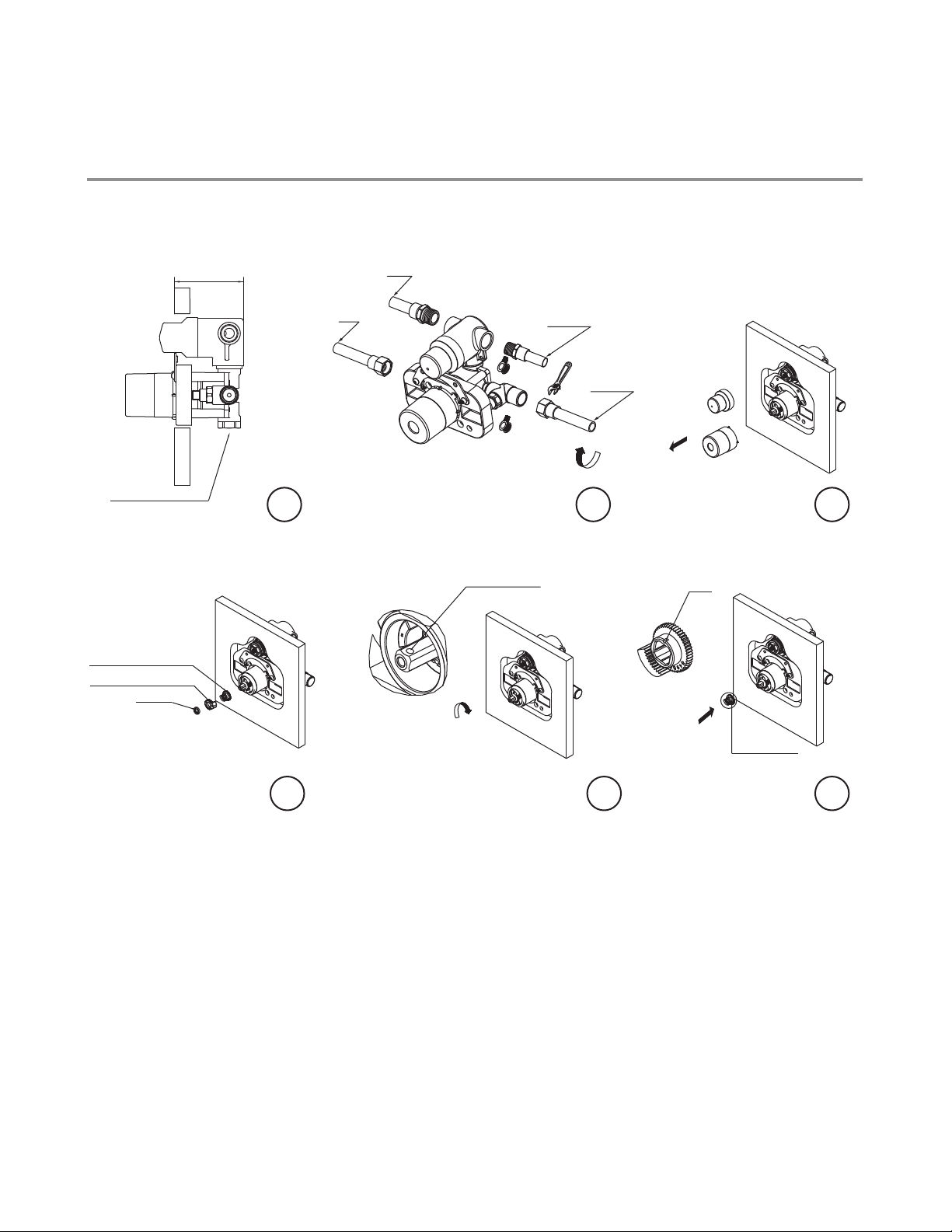
While placing the valve into the wall, make
sure that the distance between the wall
surface and the back of the valve is between
84~109mm as the figure indicates.
Connect the valve with water pipes.
Throw away the protective cap only when
the building construction is completed and
you are ready to fit the trim kit in.
REMOVE CAP ONLY, KEEP THE REST OF THE
MUD GUARD AS IT IS NEEDED TO HOLD THE
TRIM FIXING SCREWS.
4
5
6
Stopper A
(marked #049000)
5 6
Temperature Limiting Device:
Remove washer C, then take off stopper
A & B.
Turn the valve stem so that the round
dimple on the stem is at the top side.
Install stopper A onto valve stem. Notch on
stopper A should point upward.
Page 5
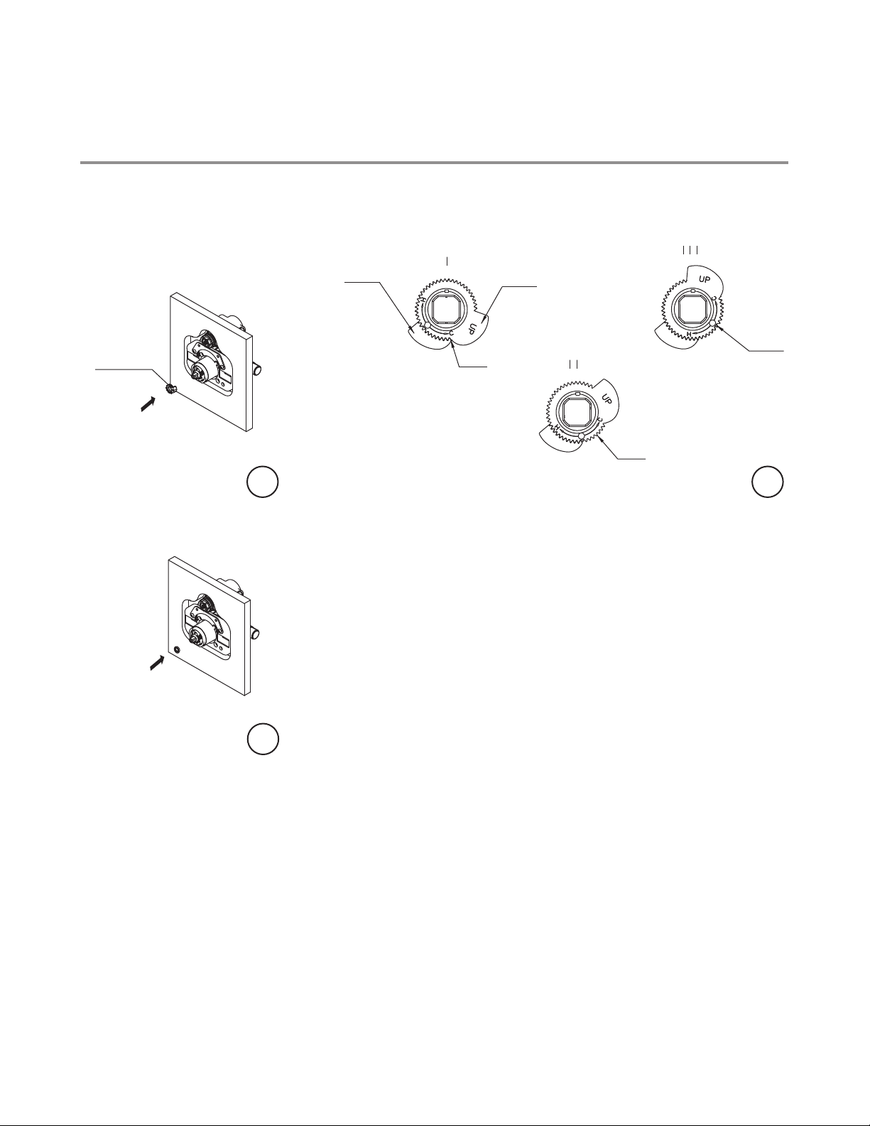
Steps 7-9
Installation Procedure
Lefroy Brooks always recommends that plumbing products be installed by a licensed professional.
Shut off main water supply before installation.
Stopper B
(marked #049001)
Stopper A
(marked #049000)
HIGHT TEMPERATURE SETTING
(with 150° operation range)
7
Stopper B
(marked #049001)
0 tooth
AVERAGE TEMPERATURE SETTING
(with 90° operation range)
12 teeth
LOW TEMPERATURE SETTING
(with 60° operation range)
8 teeth
8
7
8
9
Install stopper B. The word “up” should
face out.
Figures I, II, III show how to adjust the
temperature limit stop. Having this
open at eight notches is recommended.
Install washer.
9
5
Page 6
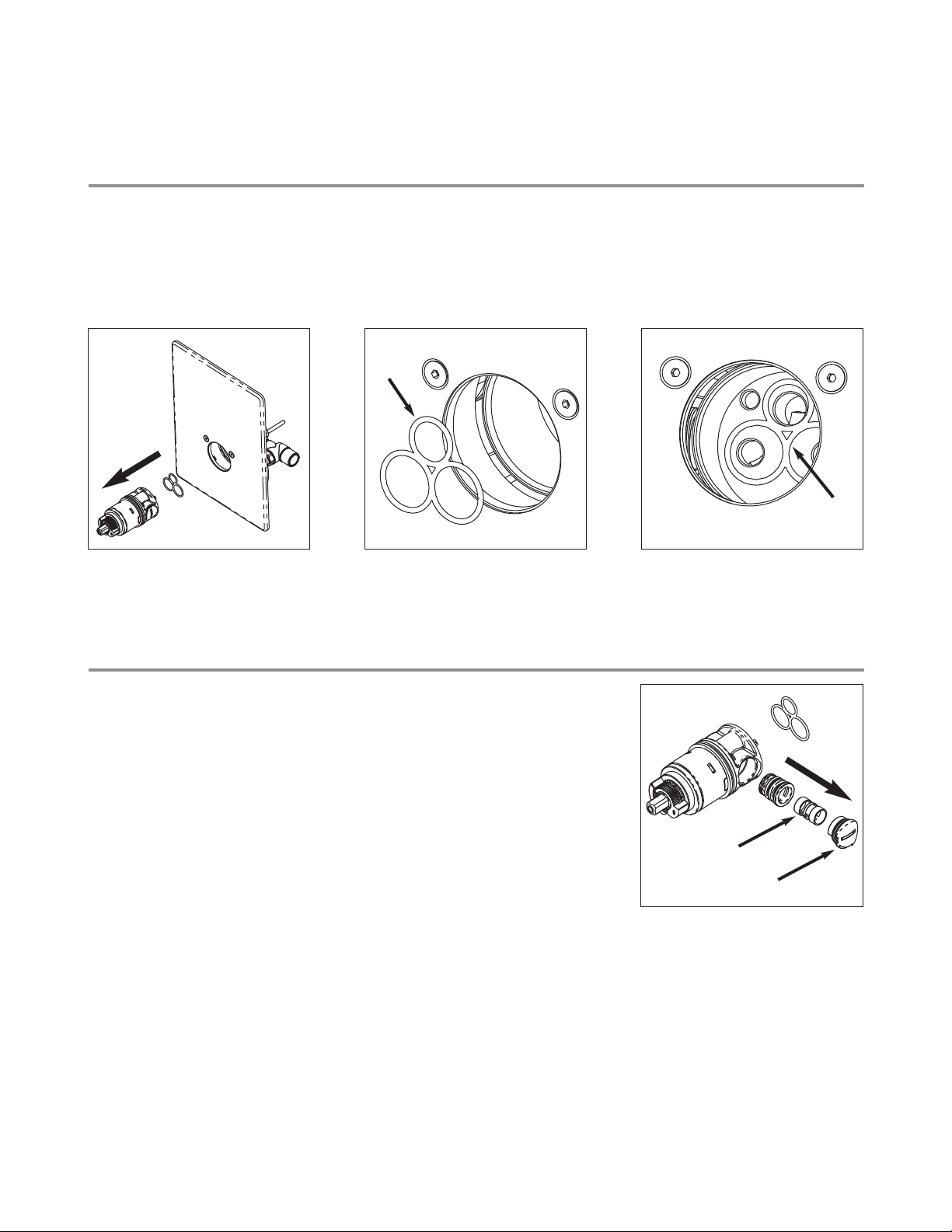
Cartridge Gasket
Whenever removing the cartridge always take care to check position of 3-hole rubber gasket (A) which sits in
the inside of the cylindrical recess of the rough (B).
Always remove with cartridge to prevent accidental loss of this small part.
(A)
(B)
Cartridge Trouble-Shooting
PROBLEM
Water temperature is not adjusting.
CAUSE
Dirty balance spool.
ACTION
1) Take out cartridge (and check 3-hole rubber gasket is not left
behind inside the cylindrical recess of the rough).
2) Turn slot of plastic cover (C) 90 degree anticlockwise and remove.
3) Take out the balance sub-assembly and clean the pressure balance
piston (D) with brush and vinegar water. Then re-install the piston
and the rest of the sub-assembly into the cartridge. (Please make
sure the sub-assembly fits correctly into the cartridge).
4) Re-install the plastic cover into the cartridge by turning it 90 degree
clockwise.
5) Re-install 3-hole rubber gasket.
6) Re-install cartridge.
(D)
(C)
6
Page 7
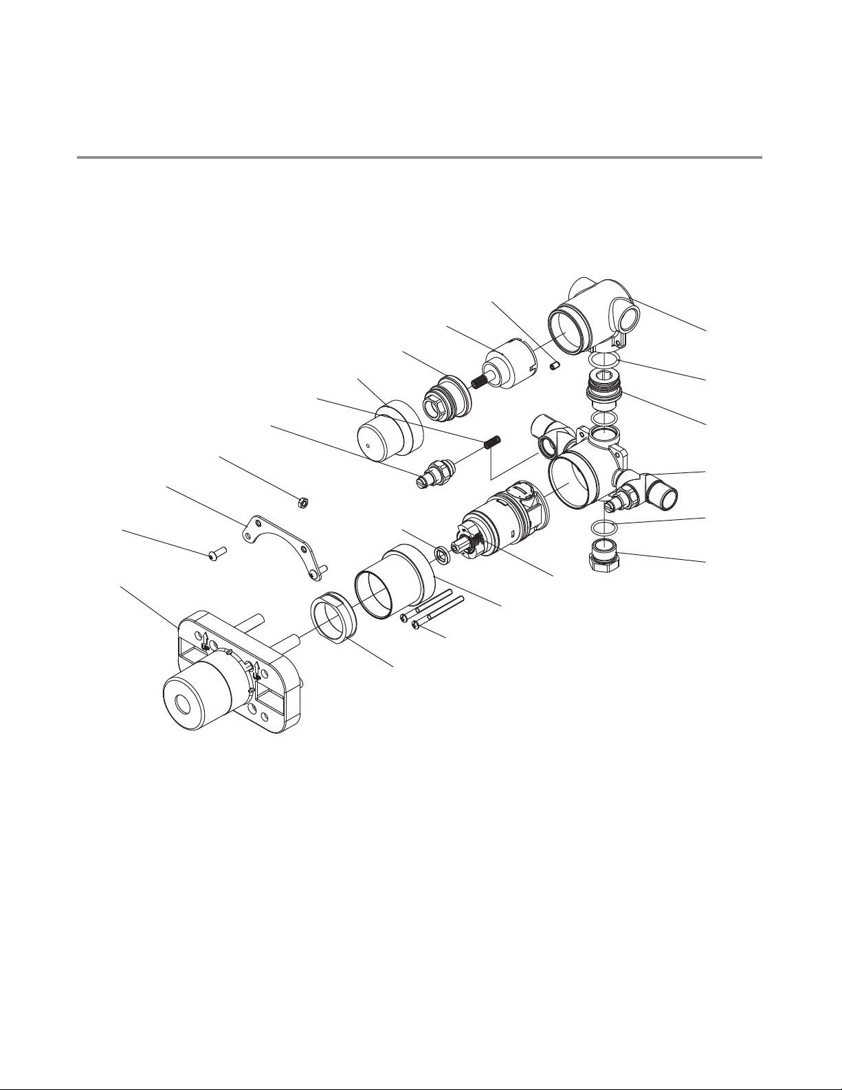
Exploded View
Parts List
M1-4102
10
9
8
7
11
12
6
5
13
4
14
3
2
21
15
16
1
17
18
19
20
1 Plaster guard (127212)
2 Screw (075083)
3 Fixing board (126055)
4 Nut (009808)
5 Check valve (507037)
6 Spring (005006)
7 Protective rubber cap (038008)
8 Adjusting ring (104291)
9 Diverter cartridge (507775N)
10 Set screw (075039)
11 Body (076697)
12 O-ring (048017)
13 Adaptor (057838)
14 Body assembly (061847)
15 O-ring (004074)
16 Plug (028599)
17 PB cartridge (507655)
18 Sleeve (041061)
19 Screw (008241)
20 Adjusting ring (104105)
21 Washer (013182)
7
Page 8

For additional assistance or service call
718-302-5292
9am to 5pm EST Monday to Friday
www.lefroybrooks.com
LEFROY BROOKS INC, 1828 TROUTMAN STREET, RIDGEWOOD, NY, 11385
registrations, trademark registrations and copyrights are protected by law and the use or reproduction outside the terms of an agreement is prohibited.
The use of trademarks, product design and artwork is subject to licence or agreement with LBIP Ltd. The design
The right to modify designs and dimensions is reserved. Christo Lefroy Brooks is a member of ACID (Anti Copying in Design).
TELEPHONE: 718-302-5292. FAX: 718-302-4177
© LBIP LTD 2012
 Loading...