

Page 1

________________________________________________________________________________________________
R Series Orbital Cutting/Beveling Machine
Operation Manual
R4, R6, R8, and R12
_______________________________________________________________________________________________
Operation Manual Page 1 of 27
Page 2

________________________________________________________________________________________________
December, 2007 Version 2. 1
Table of Contents
Section 1: Operation Safety................................................................................................................................................. 3
Keep Safety in Mind ........................................................................................................................................................ 3
Danger of death by electric shock................................................................................................................................... 4
Danger of injury by sharp cutting edges.......................................................................................................................... 4
Disposal........................................................................................................................................................................... 4
Section 2: Machine Application & Specification................................................................................................................. 5
Machine Application ....................................................................................................................................................... 5
Machine Weight and Dimension ..................................................................................................................................... 5
Technical Specification................................................................................................................................................... 6
Section 3: Assembly & Transport Instructions .................................................................................................................... 7
Scope of Delivery ............................................................................................................................................................ 8
Installation....................................................................................................................................................................... 8
Transportation and Fitting of the machine....................................................................................................................... 9
Section 4: Operation Procedure ........................................................................................................................................ 11
Install the saw blade/beveling cutter ............................................................................................................................ 11
Install additional cutters................................................................................................................................................ 12
Adjustment for different size pipe.................................................................................................................................. 14
The usage of Cut-off Stop.............................................................................................................................................. 16
Motor speed selection................................................................................................................................................... 17
Pipe cutting process...................................................................................................................................................... 18
Pipe beveling process ................................................................................................................................................... 20
Simultaneous cutting and beveling ............................................................................................................................... 22
Hard plastic cutting process ......................................................................................................................................... 22
Section 5: Maintenance & Troubling Shooting.................................................................................................................. 24
Maintenance summary.................................................................................................................................................. 24
Gear oil level check and change ................................................................................................................................... 25
Slide guide cleaning ...................................................................................................................................................... 26
Trouble Shooting ........................................................................................................................................................... 27
_______________________________________________________________________________________________
Operation Manual Page 2 of 27
Page 3

________________________________________________________________________________________________
Section 1: Operation Safety
The R series Pipe Cutting and Beveling machine are
designed to last. Please use it properly based upon the
procedure in this manual. Using it for purpose other
than those described in this manual may cause injury to
the user or to others. It may also cause damage to the
machine or other equipment.
Therefore:
• Always ensure the machine is in good working
condition and comply with these notes on safety
• Keep complete documents nearby the machine
• General valid regulations for the prevention of
accidents must be observed.
• Only use the machine for cutting and beveling of
pipes
• Damage caused by not following the manual is
user’s responsibility
• Only use the dimensions and material specified
in these instructions. Consult LEFON for cutting
material that is not covered in the manual.
• Inspect the machine daily of visible sign of wear
or damage.
• Repair any damage or defect immediately
• Only qualified electrician can work on the
electrical equipment
• Only operate the machine if the Electrical
Restart Inhibitor is working properly
• Unplug the power input before carrying out any
maintenance or repair work on the machine.
Keep Safety in Mind
• Report any unusual response from the machine
to the person in charge of this machine
• Keep Safety in mind all the time
• Wear protective goggles, safety gloves and ear
protection when working with the machine
• Keep hands off the machine during processing
• Pay attention to the surroundings. Don’t use any
electric tools in humid area. Make sure to have
excellent lighting. Do not working near
combustible liquids or gases.
_______________________________________________________________________________________________
Operation Manual Page 3 of 27
Page 4

________________________________________________________________________________________________
Danger of death by electric shock
If the main cable is damaged, live parts may cause
death when touching directly.
• Keep the main cable of the machine motor away
from the saw blade or beveling cutter
• Secure the falling pipe piece
• Don’t let the cut-off piece of pipe drop in an
uncontrolled way
• Don’t run the machine unattended
• While cutting the pipe, always pay attention to
the positions of the main cable.
Disposal
• Recycle discarded electric tools and
accessories containing valuable materials
• Dispose of chips and used gear oil according to
regulation requirement
Danger of injury by sharp cutting edges
• Keep hands away from the machine during
cutting or beveling
• Wear safety gloves
_______________________________________________________________________________________________
Operation Manual Page 4 of 27
Page 5

________________________________________________________________________________________________
Section 2: Machine Application & Specification
Machine Application
• Plastic(PE,PP,PVDE,PVC)
• Copper
• Brass
• Annealed cast iron pipe
• General structural steel
• Black and galvanized steel pipe
• Aluminum
• High quality steel (Cr<12 % and Mo< 2.5 %;
Cr<20 % and Mo=0 %)
o Case hardened steel
o High speed steel
o Tempering steel
o Bearing steel
o Tool steel
• High quality stainless steel( any Cr and Mo
content *)
* Only workable with RH
Machine Weight and Dimension
Model LxWxH (mm) Net Weight(kg) Gross Weight(kg)
R4
R6
R8
R12
_______________________________________________________________________________________________
Operation Manual Page 5 of 27
820×540×470mm 75 100
920x870x570mm 90 117
1050×590×670mm 105 133
1050×590×790mm 126 155
Page 6

________________________________________________________________________________________________
Technical Specification
Power 1600 W
Protection Double insulated
Speed 150 – 270 RPM (R2 to R12)
40 – 70 RPM (RH)
Drive Motor 1 phase AC motor
200-240 V, 50/60 Hz
100-120 V, 50/60 Hz
Cutting Range Specified in the following table
Model
½”-4”
19-120 mm
0.04”-0.22” 0.08”-0.4” 0.08”-0.4” 0.08”-0.4” Wall thickness
1-7 mm 2-10 mm 2-10 mm 2-10 mm
Motor 1600 w 1600w 1600w 1600w
Blade RPM 150-250 150-250 150-250 150-250
Voltage/
Frequency
110/220 V
50/60 Hz
75 kg 90 kg 110 kg 130 kg Net Weight
165 lb 198 lb 242 lb 286 lb
Application • Thin-wall stainless-steel tubes
• Stainless steel pips
• Low and unalloyed steel
• Casting materials, non-ferrous metal
• Copper, aluminum and plastic pipes
R4 R6 R8 R12
3”-6” 6”-8” 8”-12” Pipe OD
85-182 mm 150-230 mm 215-325 mm
110/220 V
50/60 Hz
110/220 V
50/60 Hz
110/220 V
50/60 Hz
_______________________________________________________________________________________________
Operation Manual Page 6 of 27
Page 7

________________________________________________________________________________________________
Section 3: Assembly & Transport Instructions
_______________________________________________________________________________________________
Operation Manual Page 7 of 27
Page 8

________________________________________________________________________________________________
Scope of Delivery
One set of pipe cutting/beveling machine should include
the following item. Please inform the manufacturer or
forwarder of any missing parts or transportation
damage immediately.
1. One pipe cutting/beveling machine
2. One base plate
3. Three blade
4. One ring spanner(SW22)
5. Two Hexagon socket head wrenches
6. One Tube of LEFON saw blade lubricant
7. One operation Manual
8. One Spare parts List
Installation
: Install the base plate
Step 1
Step 2
: Mark and prepare to perforate
Step 3: Drill 13 mm holes
Step 4: Install the cutting machine on base plate (follow
the procedure in next page)
_______________________________________________________________________________________________
Operation Manual Page 8 of 27
Page 9

________________________________________________________________________________________________
Transportation and Fitting of the machine
Danger of death or injury caused by electric shock
• Disconnect power before transporting, mounting
or dismounting.
• Transport and fit the machine with the aid of
crane or similar lifting device
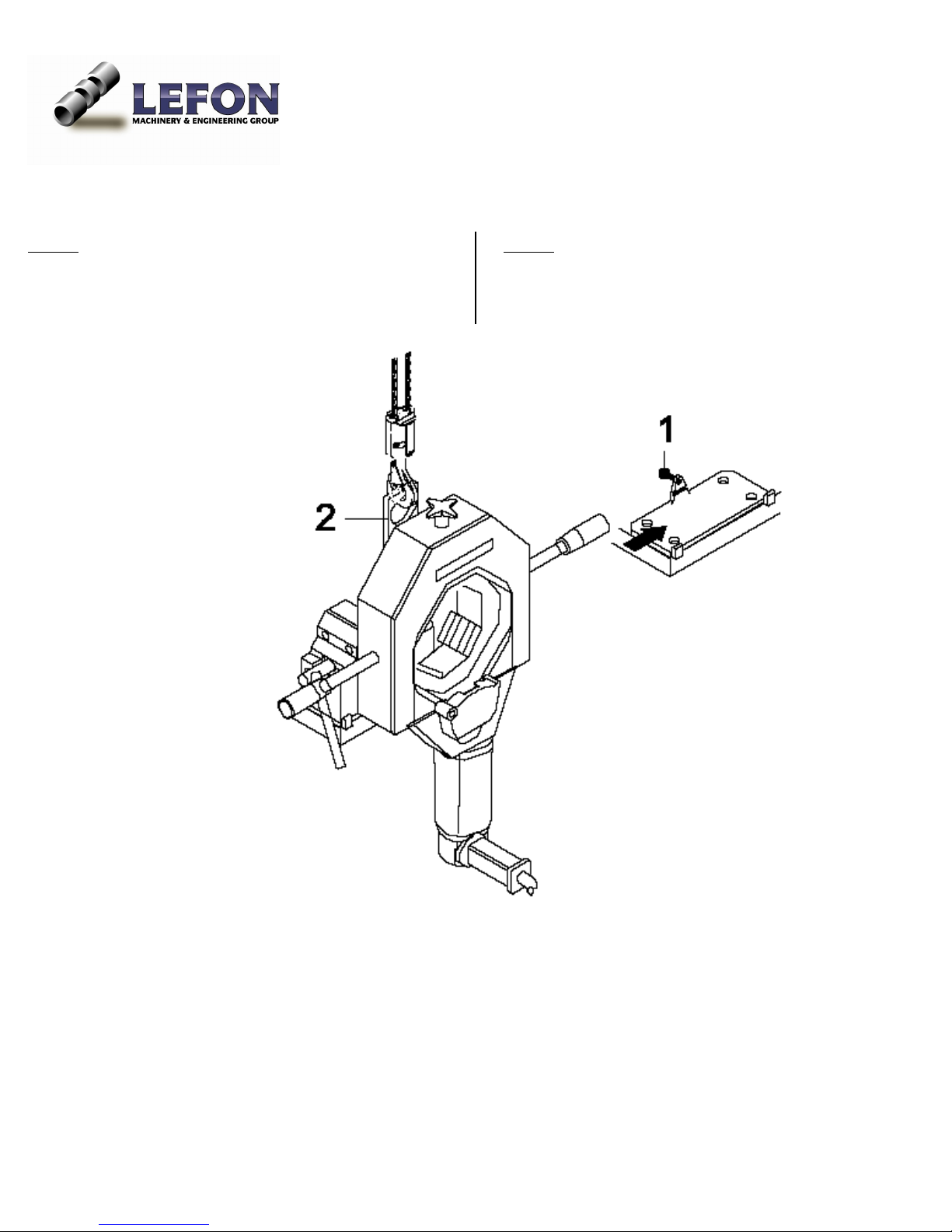
Fitting Instruction for R2, R4, R6 and R8
Step 1: Clamp a suitable pipe of sufficient length
centrically in the vice
Step 2: Position transport belts around the pipe on both
sides
Step 3: Raise the machine on the belts and guide it
sideways onto the fitted quick-assembly plate
Step 4: Bolt the machine securely in place with the
hexagon bolt (1).
_______________________________________________________________________________________________
Operation Manual Page 9 of 27
Page 10
________________________________________________________________________________________________
Fitting Instruction for R12
Step 1: Guide the hook from the crane into the shackle
(2) and slide onto the fitted quick-assembly plate from
Step 2: Bolt the machine securely in place with the
hexagon bolt (1)
the side
_______________________________________________________________________________________________
Operation Manual Page 10 of 27
Page 11
________________________________________________________________________________________________
Section 4: Operation Procedure
Danger of death or injury caused by electric shock
• Disconnect power before transporting, mounting
or dismounting.
• The cable must not contact rotating ( moving)
parts of this cutting machine
Danger of being injured by sharp cutting edges
• Keep hands off the machine when mounting or
changing the machine
• Wear safety gloves and goggle
Damage to material
• The saw blade or beveling cutter must be free of
chips and dirt
• Use only LEFON saw blades and beveling cutter
• When deploying an additional cutter, only use
the special LEFON clamp washer, not the normal
clamp washer
• Press the saw blade guard down by maximum 90
degree
• Mount the saw blade/beveling cutter or
additional cutter with the inscription facing
operator. Then the teeth will be pointing to the
correct direction.
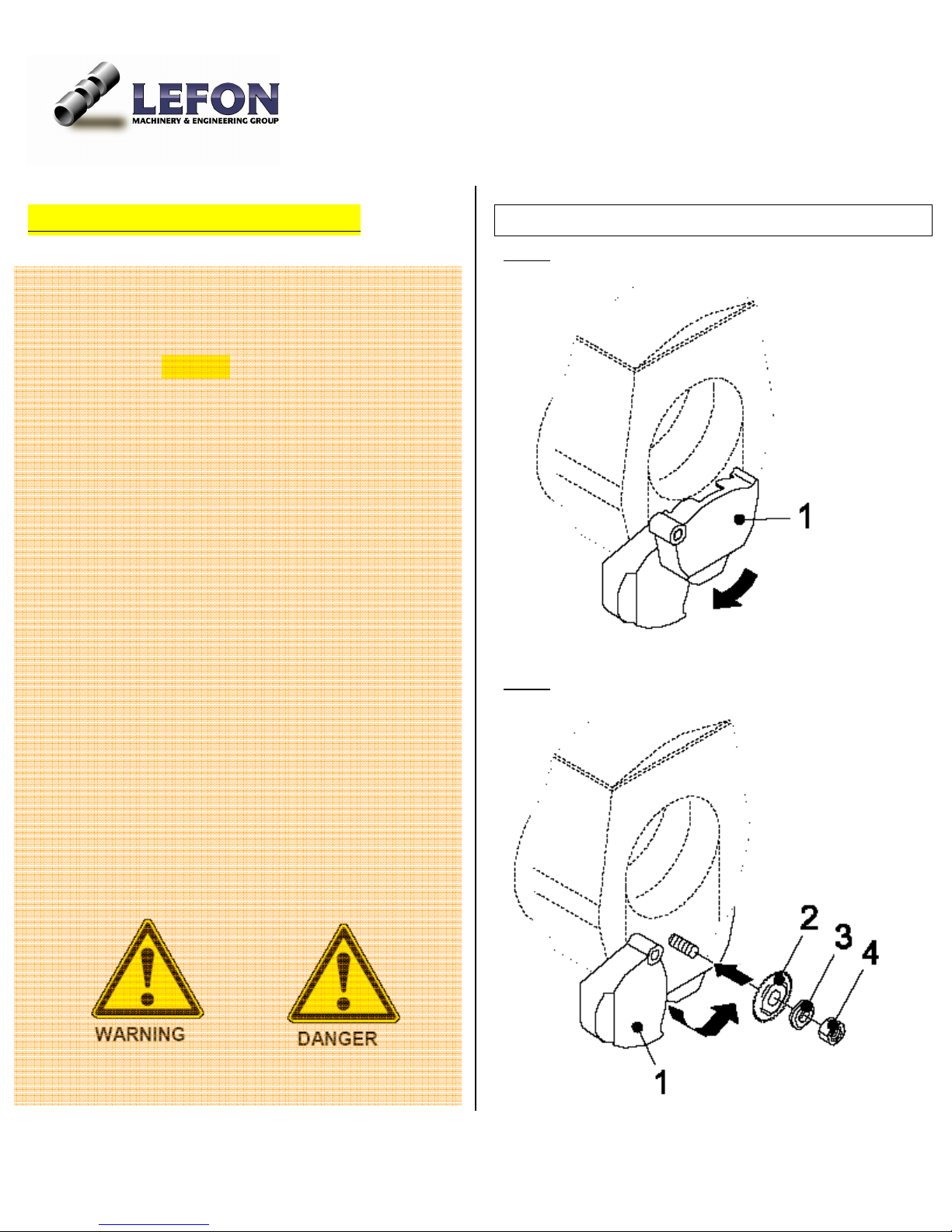
Install the saw blade/beveling cutter
Step 1: Turn the saw blade guard (1) down for approx
90°.
Step 2: Loosen the hexagon nut (4). Remove the
clamping plate (3) and the saw blade (2).
_______________________________________________________________________________________________
Operation Manual Page 11 of 27
Page 12
________________________________________________________________________________________________
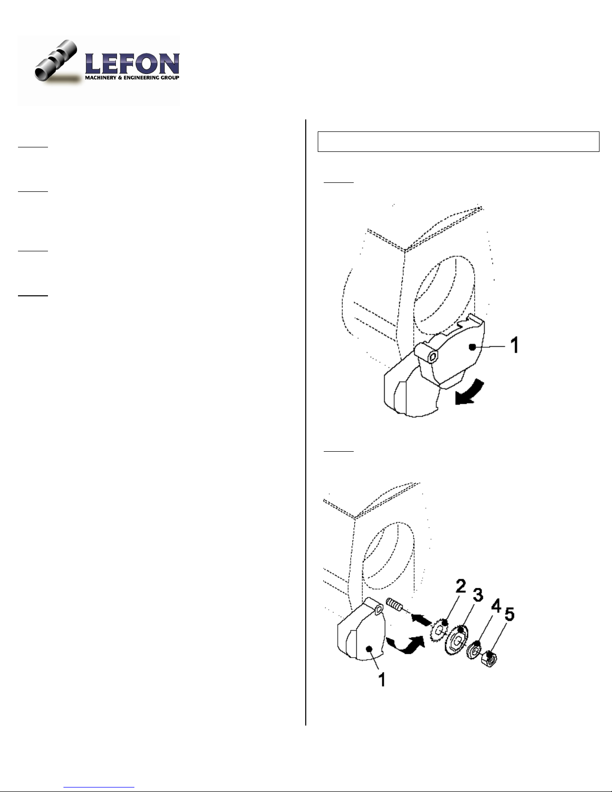
Step 3: Clean the saw blade shaft and vicinity
Step 4: Fit the saw blade (2) or bevel cutter and the
Install additional cutters
: Turn the saw blade guard (1) down for approx.
Step 1
90°.
clamping plate (3)
Step 5: Tighten the hexagon nut (4).
Step 6: Move the saw blade guard (1) back to its original
position.
Step 2: Loosen the hexagon nut (5). Remove the
clamping plate and the saw blade.
_______________________________________________________________________________________________
Operation Manual Page 12 of 27
Page 13

________________________________________________________________________________________________
Step 3: Clean the saw blade shaft and vicinity
Step 4: Fit the additional cutter (2) or saw blade (3) and
the special clamping plate (4)
Step 5: Tighten the hexagon nut (5).
Step 6: Move the saw blade guard (1) back to its original
position.
_______________________________________________________________________________________________
Operation Manual Page 13 of 27
Page 14
________________________________________________________________________________________________
Adjustment for different size pipe
Danger of being injured by rotating slide housing
When switching on the motor, the pipe cutter may
revolve around the pipe automatically.
• In their home position, the saw blade or beveling
cutter Must Not touch the pipe!
• Before switching on the motor, make sure the
gap between the saw blade/beveling cutter and
the pipe in sufficient.
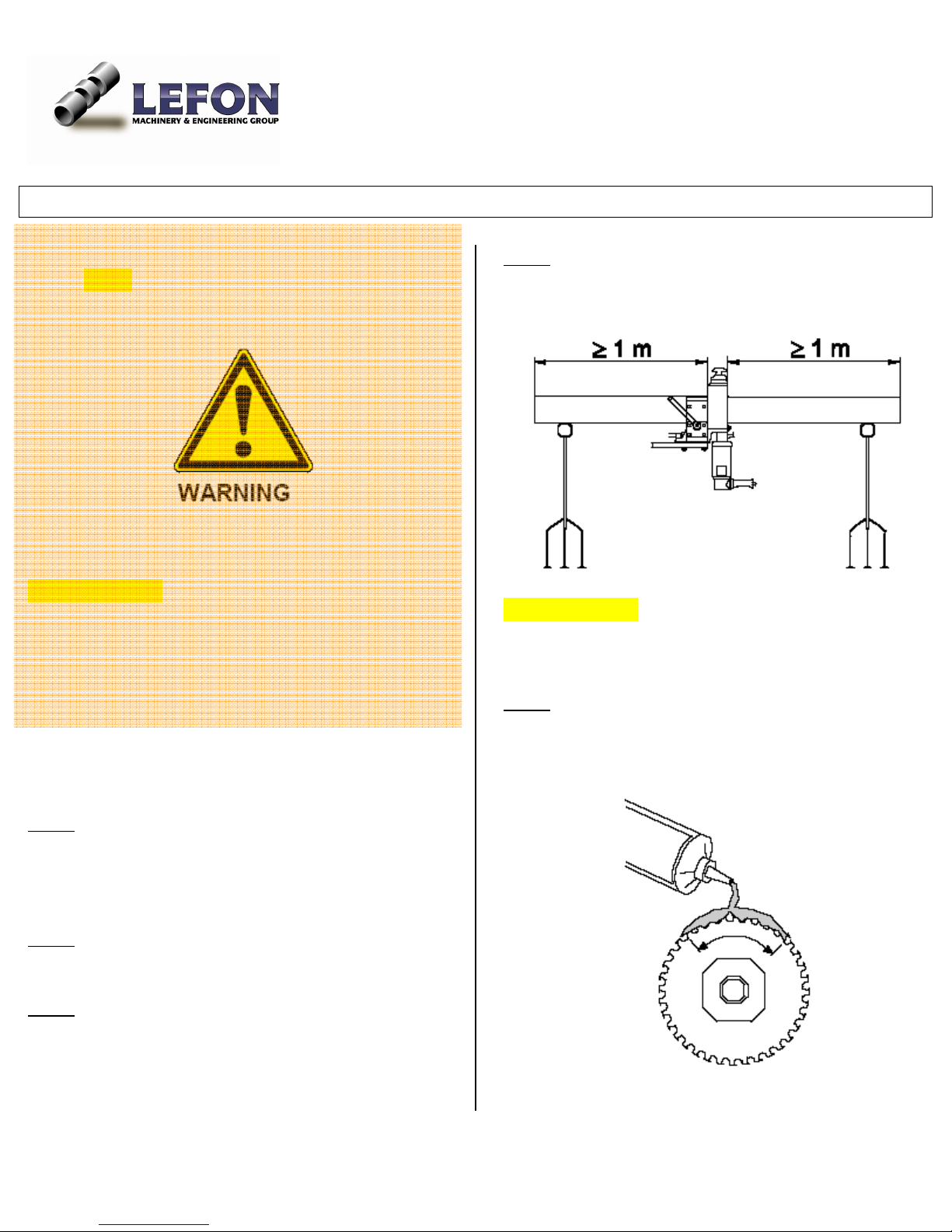
Note: It is recommended to support pipe whose one end
is longer than 1 meter with supporting device or an
auxiliary place of deposit.
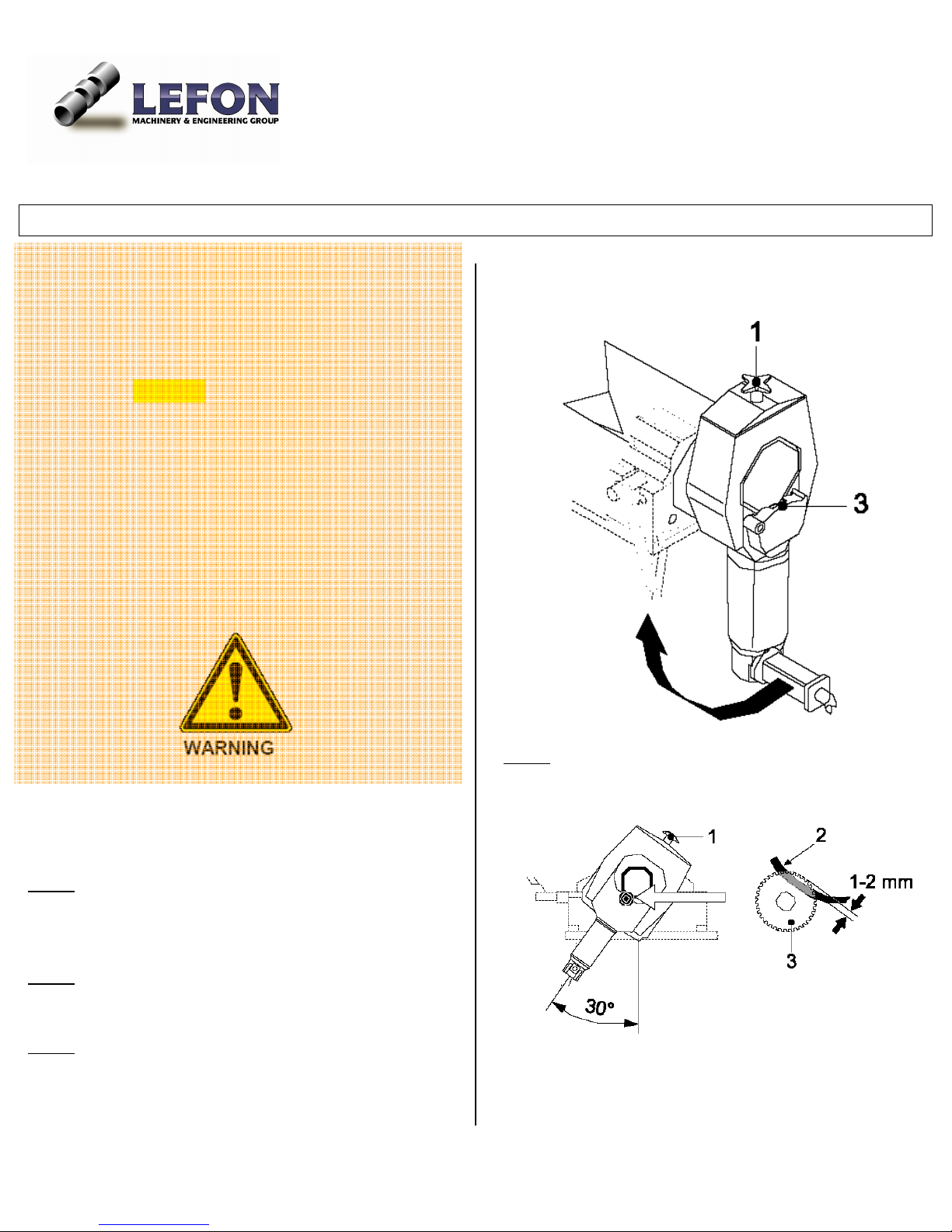
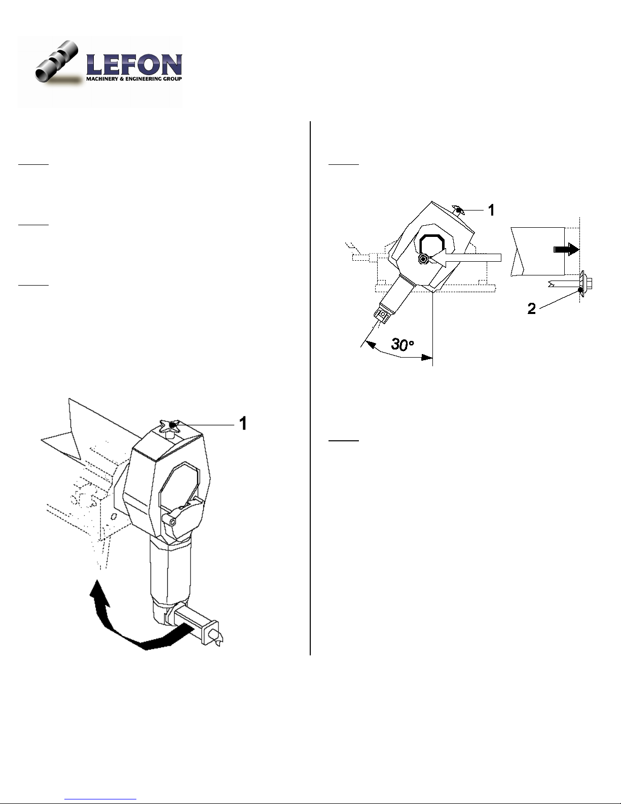
Step 4: Adjust the top handle wheel (1) until the teeth of
the saw blade (3) protrude about 1 to 2 mm inside the
pipe (2)
When only cutting blade installed
Step 1
: Adjust the top handle wheel (1) to make space
available for bigger size pipe.
Step 2: Clamp the pipe in place.
: Grip the lower handle to turn the motor
Step 3
clockwise for about 30° until the saw blade is in cutting
position
Note: scale of the hand wheel: a readjustment of one
graduation mark will result in a radial feed of bevel
alteration of 0.1mm.
_______________________________________________________________________________________________
Operation Manual Page 14 of 27
Page 15
________________________________________________________________________________________________
When cutting and beveling blade both installed
Step 1: Adjust the top handle wheel (1) to make space
available for bigger size pipe
Step 4
: Adjust the top handle wheel (1) until the
additional cutter (2) cover the wall thickness of the pipe
: Clamp the pipe in place so that it almost reaches
Step 2
the additional cutter (2).
Step 3
: Grip the lower handle to turn the motor
clockwise for about 30° until the saw blade is in cutting
position
Step 5: Perform a test cut; check the cut and beveling
result and readjust the handle wheel (1), if necessary.
Note: scale of the hand wheel: a readjustment of one
graduation mark will result in a radial feed or bevel
alteration of 0.1mm.
_______________________________________________________________________________________________
Operation Manual Page 15 of 27
Page 16
________________________________________________________________________________________________
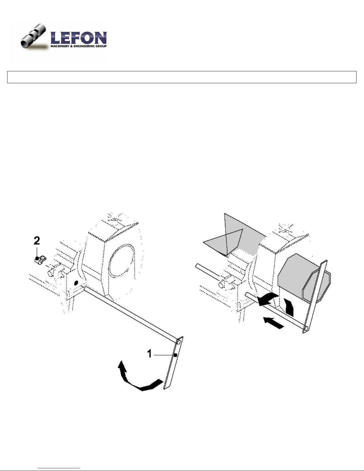
The usage of Cut-off Stop
A length gauge (cut-off stop) is available as an optional accessory for fabricating pipe sections of equal length (except
R12). Below is the instruction how to use the cut-off stop.
1. Mount the cut-off stop (1).
2. Swivel the cut-off stop to the middle of the pipe
3. Use a ruler to decide the desired length.
4. Move the clamp (2) towards the housing and turn it so that it rests on the work bench.
5. Tighten the clamp (2).
6. Move the pipe forward up to the cut-off stop and clamp it into place.
7. Swivel the cut-off stop outward and push it all the way back.
8. Cut the pipe ( refer to instruction on next pages)
9. For the next cut, extend the cut-off stop and swing it into place clockwise.
_______________________________________________________________________________________________
Operation Manual Page 16 of 27
Page 17
________________________________________________________________________________________________
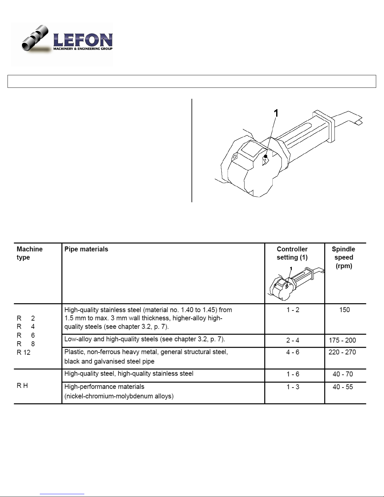
Motor speed selection
As rule of thumb, select low speed for
• Large diameter pipes
• Big wall thickness pipes
• When a supplementary cutter is used
_______________________________________________________________________________________________
Operation Manual Page 17 of 27
Page 18
________________________________________________________________________________________________
Pipe cutting process
Danger of being injured by flying chips
• Never work without the saw blade guard
mounted
• Wear protective goggles.
Important Notice: If the machine is out of operation for
long time
• Turn the cutter motor by 180°
• Switch on the machine and let the cutter motor
run for about 10 seconds
Procedure to cut the pipe
Step 1: Make adjustment to top handle wheel
Compatible for the pipe diameter.( refer to earlier
description )
: Adjust the cut-off stop if used.
Step 2
Step 3: Set the spindle speed
Step 4: Push the pipe through the vice up to the desired
length and clamp it. Support pipes at each end if the
open end is longer than 1meter.
Important Notice: Take the clamp handle off before
rotating the slide housing.
Step 5: Apply blade lubricant to the saw blade.
• Lubricant / every 3 cuts, < 2” wall thickness
• Lubricant / every 1 cut, > 2” wall thickness,
or with chrome, high quality steel pipes.
_______________________________________________________________________________________________
Operation Manual Page 18 of 27
Page 19
________________________________________________________________________________________________
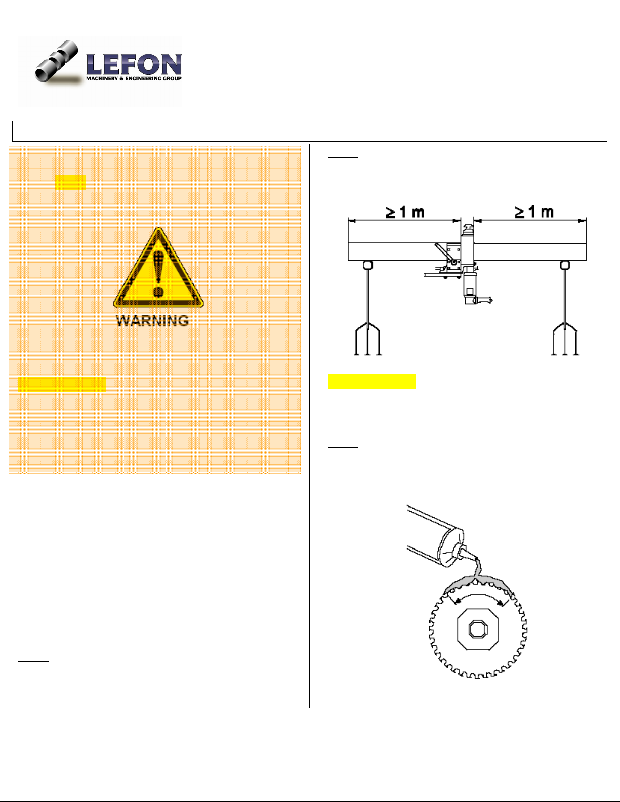
Important Notice: If the pipe got in touch with drinking
water or foodstuff, use LEFON lubricating gel on saw
blade.
Important Notice: For non-stop operation, after cutting,
loosen the hexagon nut no top of saw blade to avoid
damage caused by tension.
_____________________________________________
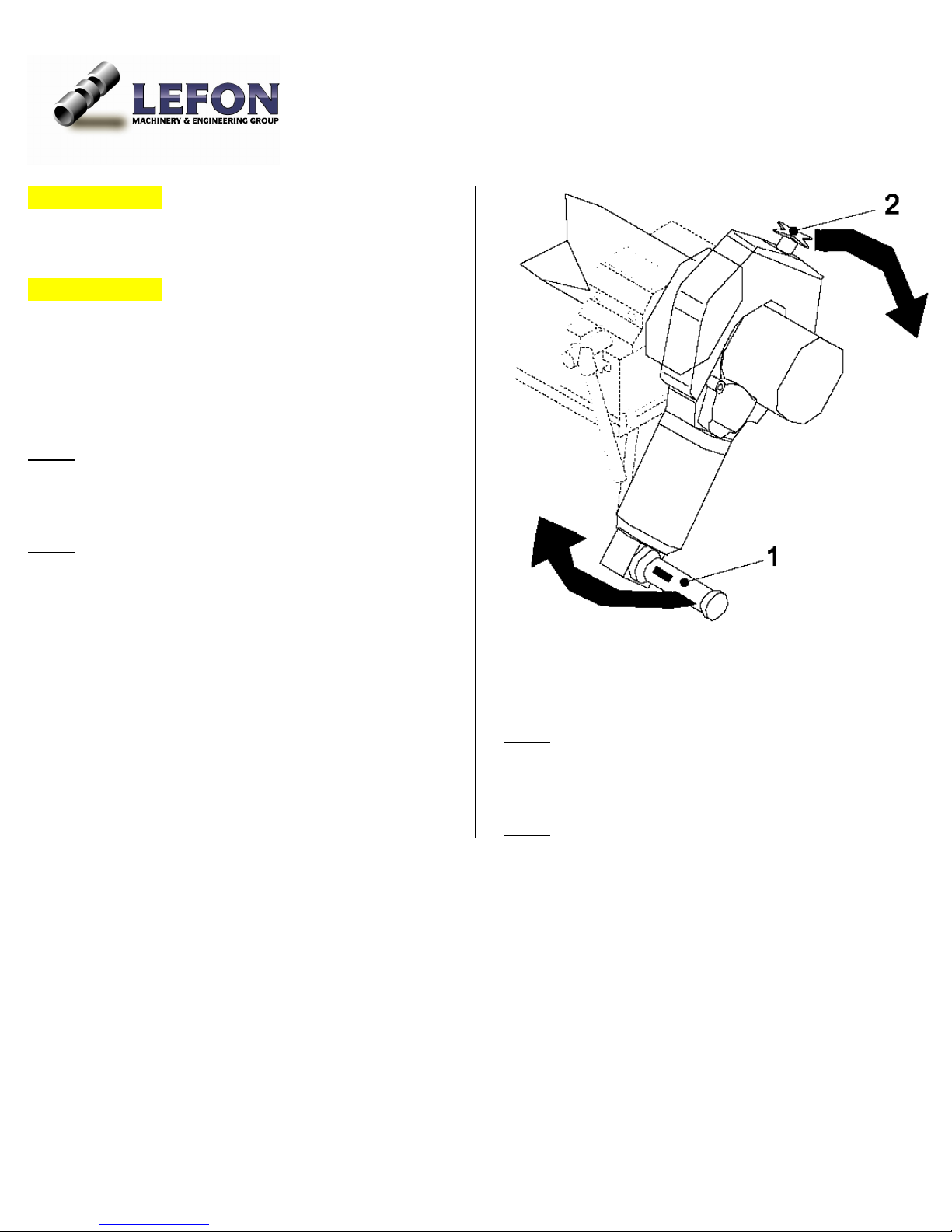
Step 6: Switch on the machine. (Soft start takes 3
seconds to initiate due to protection design)
Step 7: Slowly turn the motor using the lower grip
handle (1) and top handle wheel (2) clockwise until the
wall of the pipe/tube has been pierced through with
three or four blade teeth visible.
Step 8: Keep turning, and increase the turning speed to
cut the pipe off
: Switch off the motor.
Step 9
_______________________________________________________________________________________________
Operation Manual Page 19 of 27
Page 20
________________________________________________________________________________________________
Pipe beveling process
Danger of being injured by flying chips
• Never work without the saw blade guard
mounted
• Wear protective goggles.
Important Notice: If the machine is out of operation for
long time
• Turn the cutter motor by 180°
• Switch on the machine and let the cutter motor
run for about 10 seconds
Procedure to bevel the pipe
Step 1: Make adjustment to top handle wheel
Compatible for the pipe diameter. (Refer to earlier
description )
: Adjust the cut-off stop if used.
Step 2
Step 3: Set the spindle speed
Step 4
: Push the pipe through the vice up to the desired
length and clamp it. Support pipes at each end if the
open end is longer than 1meter.
Important Notice: Take the clamp handle off before
rotating the slide housing.
Step 5: Apply blade lubricant to the saw blade.
• Lubricant / every 3 cuts, < 2” wall thickness
• Lubricant / every 1 cut, > 2” wall thickness,
or with chrome, high quality steel pipes.
_______________________________________________________________________________________________
Operation Manual Page 20 of 27
Page 21
________________________________________________________________________________________________
Important Notice: If the pipe got in touch with drinking
water or foodstuff, use LEFON lubricating gel on saw
blade.
Important Notice: For non-stop operation, after cutting,
loosen the hexagon nut no top of saw blade to avoid
damage caused by tension.
____________________________________________
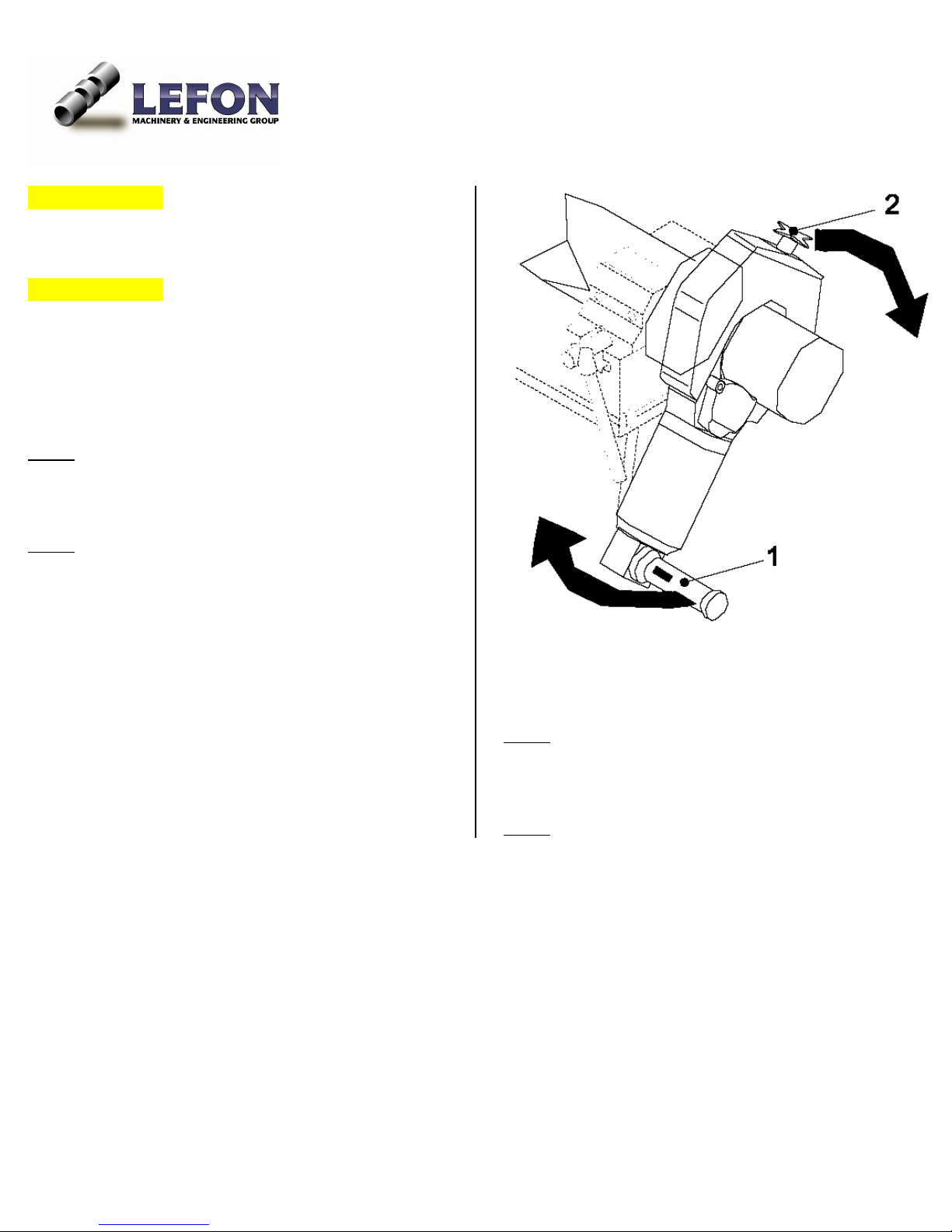
Step 6: Switch on the machine. (Soft start takes 3
seconds to initiate due to protection design)
Step 7: Slowly turn the motor using the lower grip
handle (1) and top handle wheel (2) clockwise until the
wall of the pipe/tube has been pierced through with
three or four blade teeth visible.
Step 8: Keep turning, and increase the turning speed to
finish beveling.
: Switch off the motor.
Step 9
_______________________________________________________________________________________________
Operation Manual Page 21 of 27
Page 22
________________________________________________________________________________________________
Simultaneous cutting and beveling
Pipes with less than 4.5 mm wall thickness can be cut
and beveled simultaneously.
Important Notice: If using an additional cutter, turn the
motor slower around the pipe than normal cutting.
Important Notice: Lubricate the saw blade and
additional cutter during work. For non-stop operation,
non-stop operation, after cutting, loosen the hexagon
nut no top of saw blade to avoid damage caused by
tension.
Hard plastic cutting process
For hard plastic pipe with wall thickness less than
2.5 mm
Follow the cutting procedures until Step 7
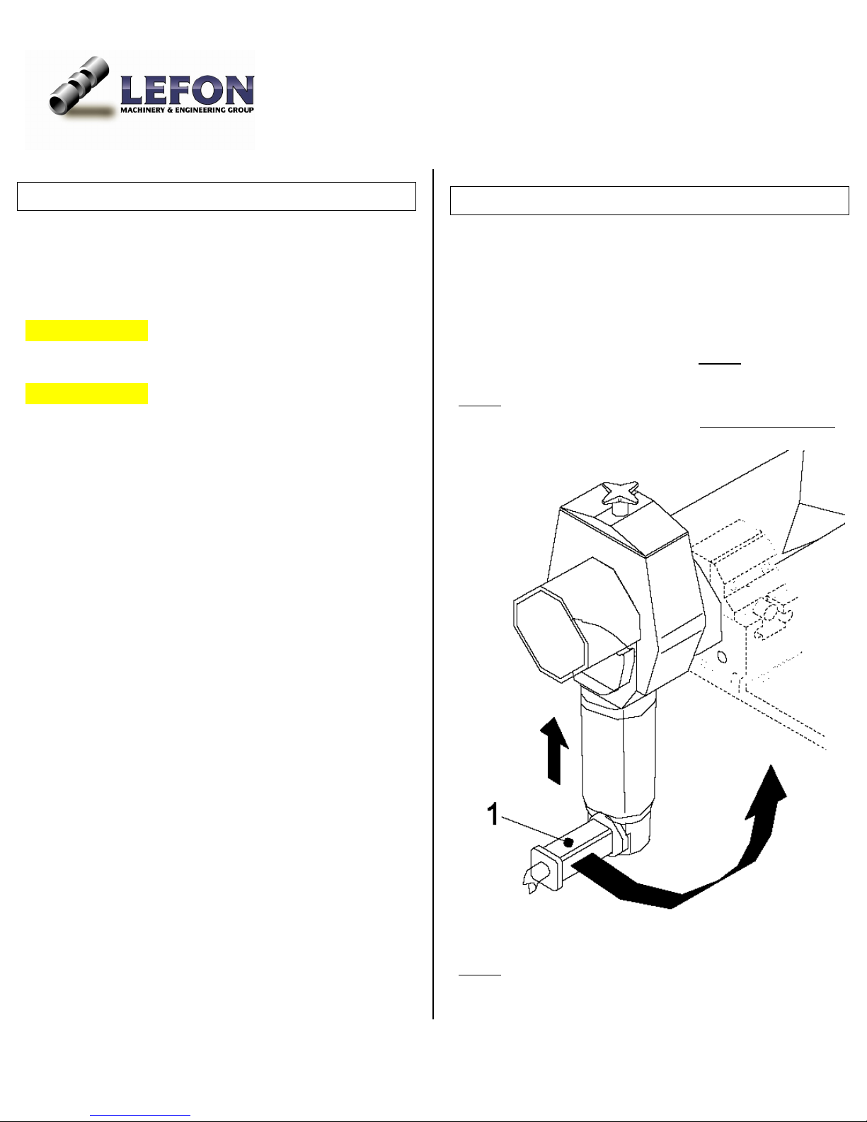
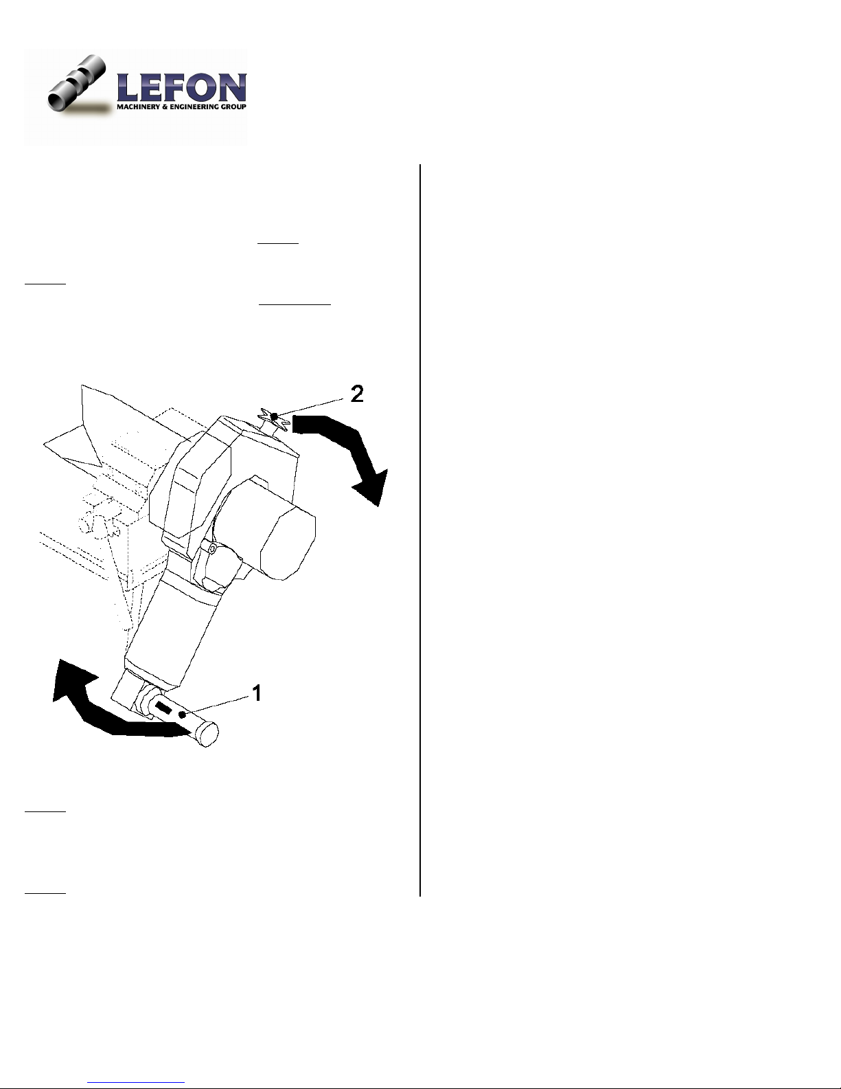
Step 7: Slowly turn the motor using the lower grip
handle (1) and top handle wheel (2) Counter Clockwise
until the wall of the pipe/tube has been cut off.
Step 8: Switch off the motor
_______________________________________________________________________________________________
Operation Manual Page 22 of 27
Page 23
________________________________________________________________________________________________
For hard plastic pipe with wall thickness more than
2.5 mm
Follow the cutting procedures until Step 7
Step 7: Slowly turn the motor using the lower grip
handle (1) and top handle wheel (2) Clockwise
until the
wall of the pipe/tube has been pierced with three or four
blade teeth visible
Step 8: Keep turning, and increase the turning speed to
finish cutting.
Step 9
: Switch off the motor.
_______________________________________________________________________________________________
Operation Manual Page 23 of 27
Page 24
________________________________________________________________________________________________
Section 5: Maintenance & Troubling Shooting
Maintenance summary
Time Interval Action
Before starting machine
Every cleaning,
Every blade change
• Remove chips and dirt from the saw blade
• Keep the vent holes free of chips
• Don’t use pressurized air to clean, which would blow cuttings into machine to
compromise the accuracy of future use
• Use cloth or brush to clean the end of the shaft
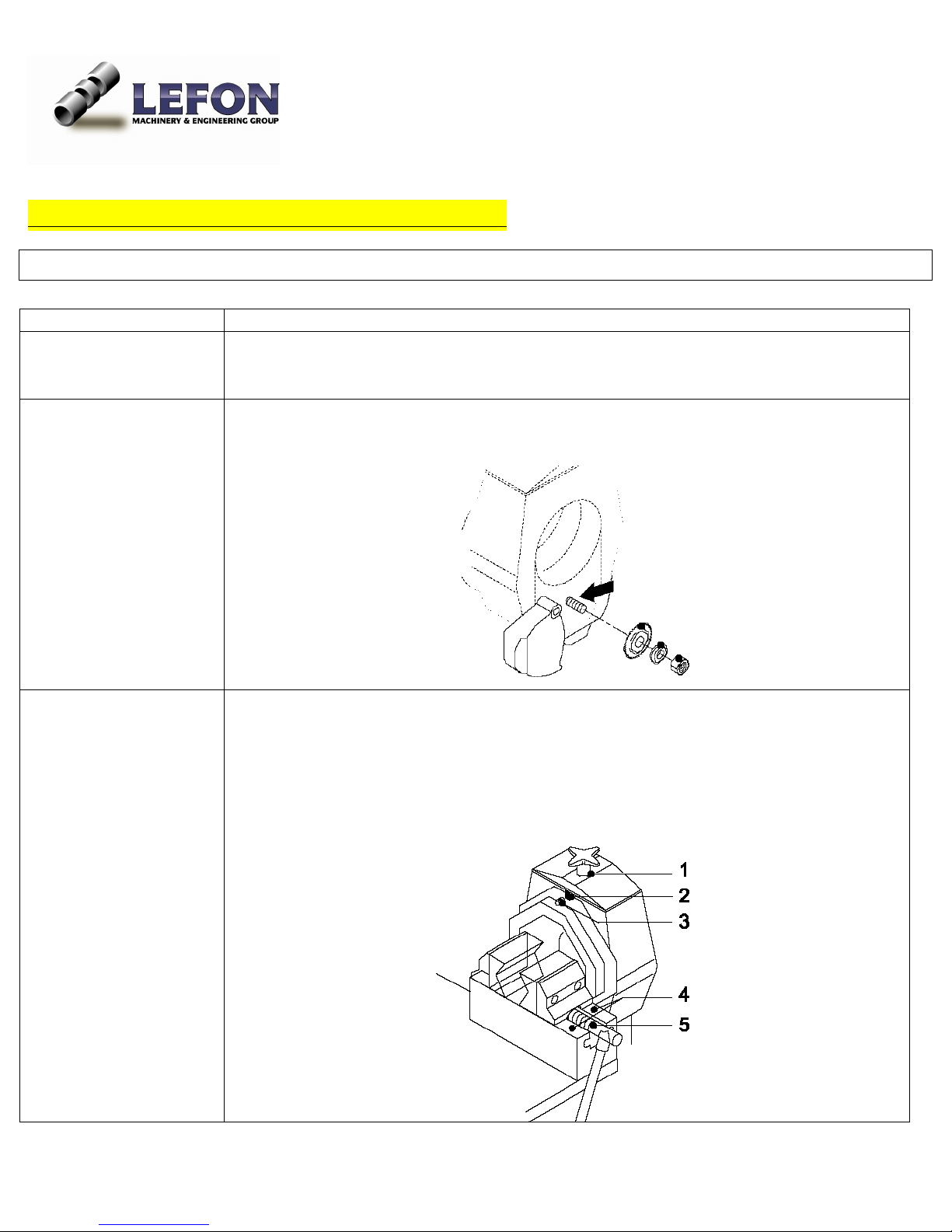
Every week
• Clean and lubricate
- The spindle of the top handle wheel(1)
- The sliding block(2)
- The guide bush(3)
- The vice track(4)
- The vice spindle(5)
• Check the gear oil level and top up (refer to next pages)
_______________________________________________________________________________________________
Operation Manual Page 24 of 27
Page 25
________________________________________________________________________________________________
Gear oil level check and change
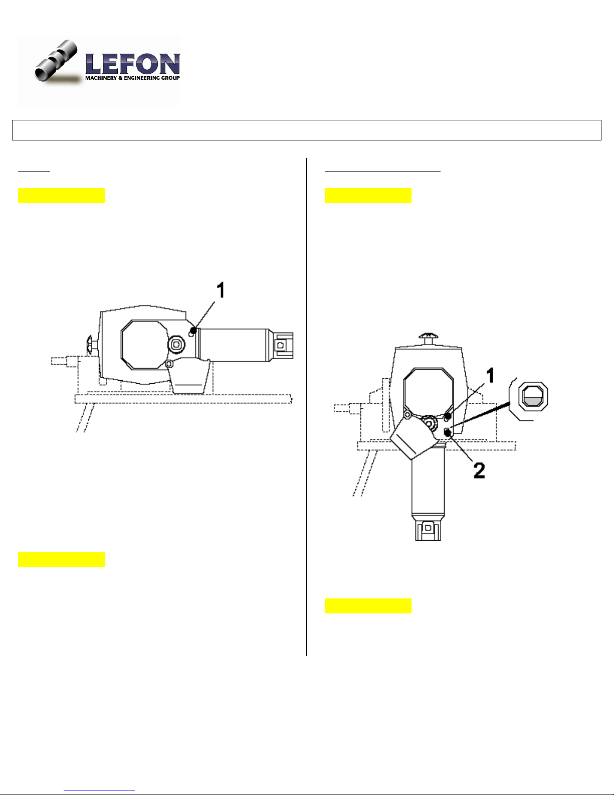
For R2
Important Notice: The pipe cutter must be mounted on
the working bench when checking oil
• Turn the motor 90° counterclockwise
• Remove the oil filler screw(1)
For R4, R6, R8, and R12
Important Notice: The gears of pipe cutters R4 to R12
have an oil level inspection tube. The oil level should be
visible in the middle of the inspection tube glass.
• Check the oil level at the inspection tube
glass(20 and top up if necessary
• Unscrew the oil filler screw (1). Fill with special
LEFON gear oil for the equal.
• If no oil runs out of the filling opening, top up
with special LEFON gear oil or the equal
• Replace and tighten the oil filler screw
Important Notice: The oil will has to be topped up if an
RA H intermediate gear is fitted
• Replace and tighten the oil filler screw
Important Notice: The oil will has to be topped up if an
RA H intermediate gear is fitted
_______________________________________________________________________________________________
Operation Manual Page 25 of 27
Page 26
________________________________________________________________________________________________
Slide guide cleaning
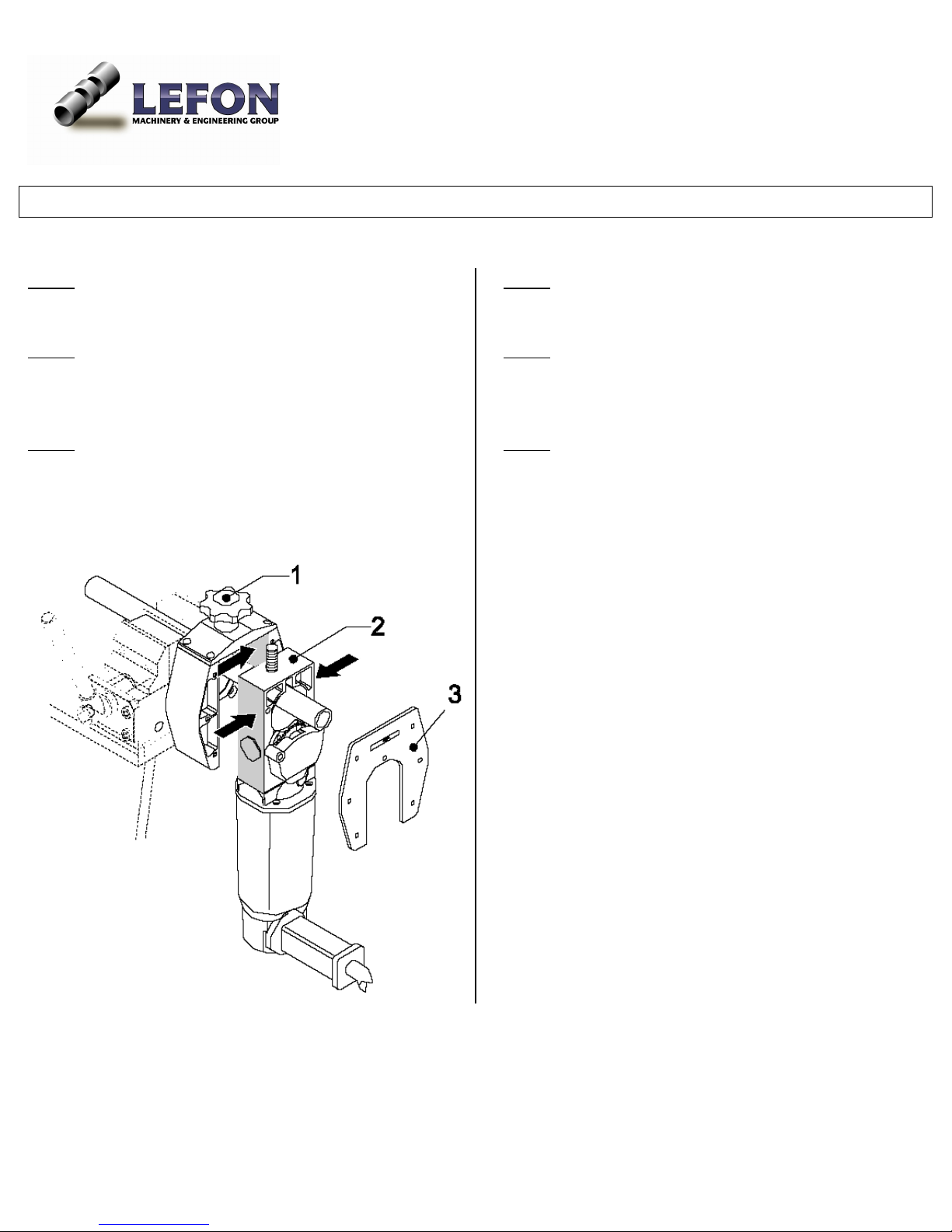
: Clamp in a suitable pipe
Step 1
Step 2
: Remove the cover plate (3) using the hexagon
Allen Key.
Step 3: Rotate the slide (2) all the way down using the
top handle wheel (1)
Step 4: Pull the slide (2) out towards the front
Step 5
: Clean the guide of the slide housing and slide.
Lubricate both parts with HD 30 engine oil.
Step 6: Reassemble the pipe cutter
_______________________________________________________________________________________________
Operation Manual Page 26 of 27
Page 27

________________________________________________________________________________________________
Trouble Shooting
Symptom Cause Correction
The sliding housing
doesn’t turn
Pipe diameter is not correctly
adjusted
Adjust the top handle wheel correctly following
earlier instruction
Blade doesn’t cut and is
slipping
Hexagon nut on the saw blade
shaft not tightened
Pipe can’t be cut Saw blade is mounted in the
wrong way
Pipe diameter can’t be
Slide guide is dirty Clean the slide guide( refer to earlier instruction
adjusted
The motor is not running
The overload protection relay
has been triggered
Tighten hexagon nut
Reverse the blade, make labeled side facing
outwards
on slide guide cleaning)
Set the switch to off, wait about 15 minutes,
and switch on the machine again
The restart inhibitor has been
triggered
Set the switch to off, then switch on the
machine again
_______________________________________________________________________________________________
Operation Manual Page 27 of 27
 Loading...