


SN-L user manual
SN-L
FixedWingFLightController + Pixel OSD
Ver 2.0
FW 5.5+
LeFeiRC
2019/1/10
1

SN-L user manual
WARING:
Please strictly observe the relevant national laws and regulations for safe flight. We do not advocate
flying high, flying far, experience the fun of the model airplane in a fully safe environment, and create a
good environment for model airplane sports! Before using the flight control, you must fully understand
the various safety details and deeply understand that the flight is risky. It is impossible to be completely
reliable on the equipment and any electronic products on the aircraft. You should use the Sinan (SN_L)
fixed-wing flight control to evaluate the product and use the system according to relevant regulations.
The system provider does not use the product for any use. Responsible for direct or indirect losses and
consequences.
i. 目录
Flight Mode: ...................................................................................................................................................... 3
How to Switch Flight Mode: ......................................................................................................................... 4
FC Iinstal: ............................................................................................................................................................ 4
Remote Contoller: ........................................................................................................................................... 6
Pre Flight checklist: .......................................................................................................................................... 7
Flight and control: ........................................................................................................................................... 8
OSD Menu ............................................................................................................................................................. 8
Firmware upgrade ............................................................................................................................................ 10
2

SN-L user manual
Interface:
RSSI Connect to receiver RSSI channel
PPM Connect to SBUS/PPM
A1 Extend other functional interfaces
A2 Extend other functional interfaces
AIL Aileron servo interface
ELE Elevator servo interface / Airspeed interface
THR ESC interface
RUD RUD servo interface
GPS Connect to GPS
PMU Power/Camera/VTX/Current, all in one interface
Connect AirSpeed Meter
Step1: set AUX1/AUX2 channel as ELE function
Step2: connect ELE servo to AUX1/AUX2 channel
Step3: connect airspeed meter to ELE channel
Step4: power on again
If you should change ELE servo direction, you should set AUX1/AUX2 channel direction
Power Supply
All the above interfaces are powered by the external 5v BEC module, and the flight controller does not output
5V to supply power to these interfaces.
Flight Mode:
MANUAL Remote control directly controls the aircraft
STAB
HORIZON
Auto level
ACRO mode + STAB mode
RTH Return to home
HOVER Altitude hold and cycle。
AH
FIX-RUD
ACRO
SUB-MODE
RTH Mode
Aircraft hold altitude and flight route(with GPS)
Keep on the route
Gyro mode
Switch mode to slave mode
When the return altitude is higher than the set height, for example, returning at a height of 150m. If the set return
altitude is 120m, the aircraft will return at a height of 150m, and then decrease the altitude to 120m when approaching
the home position. If the return altitude is less than 30m, the aircraft will climb to 30m before turning. The RC cannot
control the aircraft during the RTH mode, but the throttle can be raised by the throttle stick.
In auto cruise mode, the throttle is automatically calculated based on the speed(airspeed or ground speed). In the
case of a downwind or a large wind, the throttle can be raised by the remote control to prevent the aircraft from stalling.
for example if auto throttle is 45%, but the RC throttle is 50%, then FC output 50% throttle.
3

SN-L user manual
AltHold mode
FC will lock the route if GPS is connect. Otherwise only hold altitude.
When GPS is connected, RUD stick can change the head direction, ELE stick can control climb down/up speed; if
move AIL stick FC will enter stab mode(throttle will be controlled by RC).
How to Switch Flight Mode:
SN_L sets the RC channel 5 as the main mode switch, so the 5th channel of the RC must be set to a three-segment switch; the
subMode switch can be selected or not used when the remote controller is calibrated.
Example:
ModeSwitch subModeSwitch
STAB RTH
SUB-MODE
HOVER
MANUAL ALtHold
FC Iinstal:
① PMU Module
② Install direction
4 install direction:<BASE FUNCTION> -> <AP DIRECTION>
0° Arrow point to head
180° Arrow point to rear
90° Arrow point to left
270° Arrow point to right
The FC installation should try to avoid the vibration source and keep away from the motor; try to install it near the center of
gravity. Be sure to recalibrate the level after changing the installation direction
③ How to connect servo
Interface
Type
Wing Servo1 Servo2 ESC ALL ALL
T tail AIL servo ELE servo
V tail AIL servo ELE servo1 ESC ELE servo1
AIL ELE THR RUD AUX1 AUX2
ESC RUD servo
ALL ALL
ALL ALL
It is recommended that you use an external 5v power module to servos and receiver.
AUX channel
AUX channel can extend other functions, such as outputting RC channels, or multiplexing AIL,ELE,THR.
4

SN-L user manual
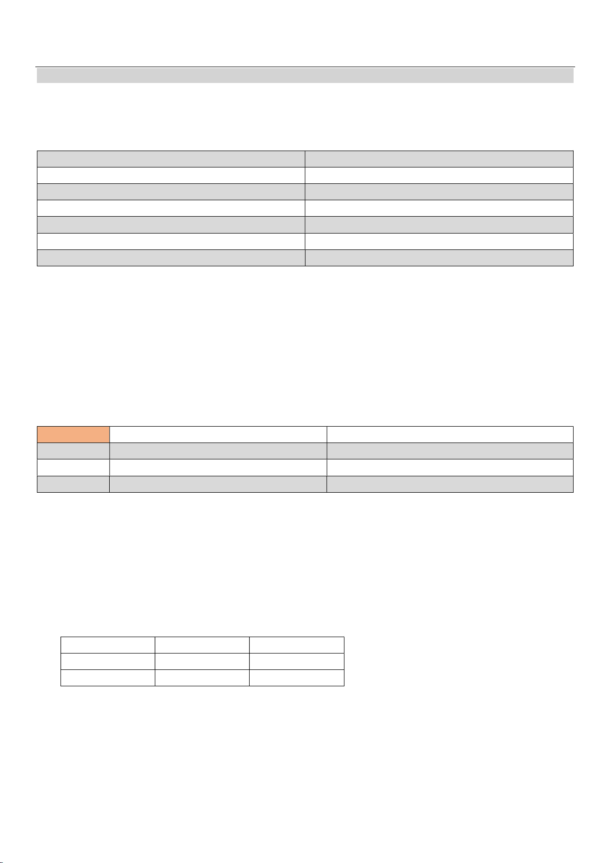
④ Correct Control Surfaces Movement
Switch to stab mode, your servo should move like this:
OSD Picture:
Waring info
Flight mode
Ground speed
Air speed
Alt
Total voyage
It is recommended to use a PAL camera to get a more detailed picture.
After Landing, OSD will show flight summary.
Speed unit’ Km/h’ or ‘Mile/h’; Alttitude unit ‘m’ or ’Ft’.
Home Distance
5
SN-L user manual
Remote Contoller:
Calibrate RC
Please make sure all channels of AIL,ELE,THR,RUD are in the first four channels.
Make sure the 5 channel as mode switch is a three-segment switch.
When a new RC is connected to the FC, it will pop up a calibration screen:
Page1:reset all channels,flip mode switch enter next step Clear all offsets, sticks is homed, and the RC does not set the range limit
Page2:throttle Up,flip mode switch enter next step Get throttle MAX value
Page3:throttle Down,flip mode switch enter next step Get throttle MIN value
Page4:Keep the AIL stick to the Left, flip mode switch enter next step Get AIL channel MIN value
Page5:Keep the ELE stick to the Down, flip mode switch enter next step Get ELE channel MAX value
Page6:Keep the RUD stick to the Left, flip mode switch enter next step Get RUD channel MIN value
Page7:flip subMode switch,flip mode switch enter next step Detect subMode switch
Enter RC Calibrate:<BASE FUNCTION> -> <CALI RC>
① When you can’t enter RC calibrate menu for some reason; follow steps like this:
Power on FC -> make RC sticks move to the side-> wait until RC calibrate menu display
② Before OSD initialization is complete, don’t move sticks, otherwise you would enter RC calibtate menu again
③ After calibrate,don‘t change RC thrim
FailSafe
PPM receiver FC can’t recognize whether the RC is out of control, need to be set in advance.
SBUS receiver can automatically identify if it is out of control
Enter OSD menu <BASE FUNCTION> -> <FAILSAFE MODE>
FAILSAFE MODE
HOLD Hold current mode Hold current mode
RTH Return to home Switch to stab mode, close throttle, Circling down①
STAB Switch to stab mode, close throttle, Circling down Switch to stab mode, close throttle, Circling down
①The AIL is 10 degrees to the left, the ELE is 15 degrees down, and the throttle is closed.
RSSI
Support independent RSSI and RSSI signal channels in SBUS or PPM signals; can be selected by OSD menu.
The independent RSSI automatically recognizes the RSSI signal type, PWM or AD type; the RSSI signal of some models of
receivers may cause the OSD picture to flicker due to the RSSI modulation into a high frequency pulse signal.
FC does not return to home based on the RSSI signal value.
If connect a SBUS receiver, you Set RSSI channel to 18 , <OSD SETTINGS MENU>-<SENSOR>-<RSSI CHANNEL> , FC will auto
calculate RSSI according to SBUS signal packet loss rate.
ARM&DISARM
Satellites <=6 >6
GPS connect DISARM ARM
GPS disconnect ARM ARM
*If flight mode is manual mode, you can control the throttle in any situation
GPS connect, satellites>6 GPS disconnect/GPS lose signal
6
SN-L user manual
Pre Flight checklist:
1 Check the rudder feedback is correct
2 Check the firmware version to keep the firmware up to date
3 Check if the FC attitude line is level. If it is not calibrated for a long time or the temperature changes too
much, you need to recalibrate.
4 Check if the battery voltage
5 Confirm the position of each mode
6 Confirm that the Home location has been updated.
7 Confirm the vibration of the body and open the acceleration curve display. If the vibration is too large, the
attitude will be disordered. It is recommended to keep the vibration amplitude within the warning line
while maintaining horizontal flight.
* Recalibration level is also required after changing the direction of FC installation
* If you do not calibrate for a long time, or if the temperature changes too much, you need to recalibrate level (even if the attitude line
looks level)
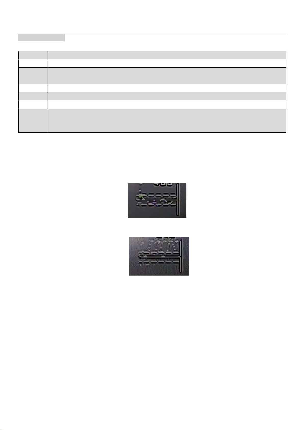
Check accel health <OSD>-<SCOPE>-<HEALTH>
① The vibration is in good condition. When the plane is flying flat, the vibration point is scattered within the two
warning lines.
② The vibration is large, and most of the vibration points fall outside the warning line, which easily leads to the
FC can’t calculate the correct attitude
Calibrate Level
Ensure that the aircraft is level and stationary during horizontal calibration.
① Horizontal calibration is required after changing the mounting direction.
② If you have not calibrated for a long time or the temperature difference has changed too much, you need to
recalibrate.
Sensitivity adjustment
Sensitivity adjustment follows a simple rule that the smaller the wingspan, the smaller the sensitivity; the
faster the flight speed, the smaller the sensitivity.
Two points to note for gain adjustment:
1 <BASE FUNCTION>---<AIL BASE GAIN> <ELE BASE GAIN> <RUD BASE GAIN>: The larger the value, the faster
the reaction speed and the excessive jitter.
2 <ADVANCE FUNCTION>---<STAB GAIN>---<FEED FORWARD GAIN>: The larger the value, the faster the
response joystick will be, and the jitter will be exceeded.
7

SN-L user manual
Adjustment steps:
Step1: set <FEED FORWARD GAIN>, normally reduce feed forward gain to 40
Step2: Set the <AIL BASE GAIN> <ELE BASE GAIN> <RUD BASE GAIN>. The span of 1m or less can set The parameter
to about 45. If it exceeds 1m, it can be defaulted.
After the parameters are set, you can fly test; firstly fly in manual mode, check whether the aircraft is
mechanically balanced; then switch to the stabilization mode. If the aircraft is found to be shaking during the
flight, reduce the sensitivity in the basic settings. If the aircraft is found to be unresponsive, then The sensitivity
of the basic setting can be appropriately increased; under the premise that the basic sensitivity is set, the size of
<FEED FORWARD GAIN>, can be appropriately increased. The larger the value, the more the aircraft follows the
action of the RC sticks, but too large will cause the aircraft to shake.
Flight and control:
When a small arrow appears in the center of the screen, it indicates that FC has get “home” position; it can take off
right now. You do not need to check this if you don‘t connect GPS.
Auto TakeOff
① AltHold Mode: Push the throttle to enough power and the aircraft will automatically climb to a height of 10m.
② RTH Mode: Push the throttle stick away from the lowest position (if the throttle stick is at the lowest level below 20m, the
motor will never start), give plane a speed until motor start. It is recommended that the hand throw speed be 2-3m/s and
the ejection speed be 10-15m/s.
Throttle and speed control
① Airspeed meter disconnect
Speed is controlled by the ground speed, curise speed is setted in <ADVANCE FUNCTION>-<CURISE SPEED>.
② Airspeed meter connect
Airspeed control keeps the aircraft from getting enough lift.
In the case of connecting an airspeed meter, the speed of the aircraft is determined by the airspeed meter, and
the airspeed is also controlled in the altitude mode. When the aircraft is less than <MIN GROUND SPEED>, the speed of
the aircraft is kept at the minimum ground speed, preventing the aircraft from stopping in the event of a headwind
and swinging left and right. In general, it is recommended to set<MIN GROUND SPEED> to about 10m/s.
OSD Menu
Enter OSD menu Flip mode switch twice
AIL move left Exit the current menu or exit the selected mode
AIL move right Enter menu or select setting item
ELE move up or down Change item index or select parameter
* in flight can’t enter the setup menu
Flight summary
After the landing, the OSD screen will display the flight summary, and each component will display the maximum
value. Restart the flight control to eliminate the flight summary.
8
SN-L user manual
BASE FUNCTION
1.3 AIL BASE
FUNCTION
1.4 ELE BASE FUNCTION
1.5 RUD BASE FUNCTION
1.1 AIRFRAME TYOE
1.2 AP DIRECTION
1.7 FLIGHT MODE
1.8 WARING BATTARY Voltage warning value, OSD will prompt low voltage information
1.9 AUX
2.0 CALI RC Remap RC channel, get cannel range and direction
2.1 FAILE-SAFE MODE
2.2 RESET HOME updata home location
2.4 UNIT Switch metric system: “M”/”Ft”; m=”m,m/s, km/h”; Ft=”Ft, Mile, Mile/h”
2.3 RESET SETTINGS Reset all settings
1.6 SERVO
The default gain can be adapted to most models.
The heading gain only works in the T-tail type. The V-tail and the delta-wing heading are
manually controlled, and the flight control does not participate.
T-Tail, V-Tail, Wing
0, 180, 90
AIL EXP
Adjust the exp of the RC, the larger the value, the smaller the control amount
near the center of the joystick; it only takes effect in the MANUAL mode.
AIL TRIM
AIL RANGE
Adjusting the servo offset , can be used to fine tune the rudder surface.
Adjust the rudder amount of the RC. The smaller the value, the smaller the stroke
of the joystick control servo.
ADVANCE FUNCTION
2.1 ADVANCE STAB GAIN
2.2 CONTROL RATE Control the rotation speed of the aircraft's roll and pitch. The larger the value, the more flexible
2.3 MAX ROLL ANGLE
2.4 MAX PITCH ANGLE
2.5 RTH ALT The lowest altitude in the home mode, when the aircraft returns, it will hover according to this
2.6 HOVER RADIUS
2.7 MIN GROUND SPEED When airspeed is connect
2.8 TAKE-OFF SPEED In the home mode, trigger the speed at which the motor starts (ground speed); used to assist
2.9 CURISING SPEED
3.0 CURISING BASE THR
3.1 CURISING MAX THR
3.2 FAILSAFE TIME 0-3s ①
ALT-HOLD GAIN
SPEED GAIN
NO NEED
In the case of automatic cruising, if the throttle changes in a wave
shape, this value needs to be reduced.
FEED-FORWARD GAIN
The adjustment range is 0~100; the larger the value, the more flexible
the hand feel, the default is 70. If this value is too large, it will cause
the aircraft to shake. The small aircraft is recommended to be set to
around 35-45.
the aircraft, and the larger the wingspan can be set larger.
height
the takeoff; hand throw 3-5m / s; ejection 15m / s;
① For example, if it is set to 3s, when the remote control is out of control, wait for 3s before entering the
failsafe mode(RTH mode).
9

SN-L user manual
传感器
3.1 CALI LEVEL&GYRO
3.2 CALI BATT
3.3 CALI COMPASS NO NEED
RSSI CHANNEL RSSI CHANNEL:“0”= Independent RSSI channel wiring
3.4 CALI RSSI
Keep the aircraft level, and still
“1-17”= Map the corresponding RC channel
“18”=auto calculate RSSI(SBUS)
Firmware upgrade
The way of get firmware and user manual:
www.lefeirc.com
https://github.com/HelloLeFei/SN_L/releases
Step1: Download upgrade software and drivers and install:
Please install “CP210x USB to UART Bridge” driver.
Step2: download firmware:
Step3: open FL software:
Step4: connect FC:
10

SN-L user manual
Don’t power on FC at first !
Connect the upgraded board like this picture; check the serial port number in the computer management.
Then select the corresponding serial port number in the software.
And click on "connect"
Step5: Load firmware and update
Click the "open" button to load the bin file, then click flash;;
The computer will have a 10s countdown, please power on the FC within 10s;
After the FC is powered on, the firmware will be written; 100% indicates that the updata firmware is successfully!
11
 Loading...