

Leeson 175290.00, 175292.00, 175291.00, 17529X.00 Series User Manual

Models:
175290.00
175291.00
175292.00
Pulse-Width Modulated,
Adjustable Speed Drives
for DC Brush Motors
User’s Manual
17529X.00 Series

The LEESON 17529X.00 Series drives are chassis drives that
accept a DC input voltage and output a DC power voltage to
control the speed of a low voltage motor. The speed may be
controlled with a potentiometer or an external voltage signal.
Standard Features:
• Provides smooth variable capability for mobile equipment.
• Maintains variable speed control as batteries discharge.
• Adjustable min speed, max speed, IR compensation, current
limit, and accel.
• Inhibit terminal permits optional start-stop without breaking
battery lines.
• Speed potentiometer included.
• Increases range OR running time of battery operated
equipment through high efficiency.
• Power LED gives a visual indication when power is applied to
the drive.
• Jumper reconnectable for low or high voltage.
Copyright © 2002 by
LEESON Electric
All rights reserved. No part of this manual may be reproduced or transmitted in any
form without written permission from LEESON Electric. The information and
technical data in this manual are subject to change without notice. LEESON Electric
makes no warranty of any kind with respect to this material, including, but not limited
to, the implied warranties of its merchantability and fitness for a given purpose.
LEESON Electric assumes no responsibility for any errors that may appear in this
manual and make no commitment to update or to keep current the information in this
manual.
Printed in the United States of America.

i
Safety Warnings
• This symbol denotes an important safety tip or warning.
Please read these instructions carefully before performing
any of the procedures contained in this manual.
• DO NOT INSTALL, REMOVE, OR REWIRE THIS EQUIPMENT
WITH POWER APPLIED. LEESON assumes the qualified
technician is intimate with the dangers involving batteries,
especially lead-acid type. This manual presupposes that you
have taken all the necessary precautions to prevent a potentially
fatal accident involving such batteries, and have followed all
standard electrical precautions.
• Reduce the chance of an electrical fire, shock, or explosion by
proper grounding, over-current protection, thermal protection,
and enclosure. Follow sound maintenance procedures.
It is possible for a drive to run at full speed as a result of
a component failure. LEESON strongly recommends the
installation of a master switch in the main power input to stop
the drive in an emergency.
This drive is isolated from earth ground. Avoid direct
contact with the printed circuit board or with circuit elements to
prevent the risk of serious injury or fatality. Use a non-metallic
screwdriver for adjusting the calibration trimpots. Use
approved personal protective equipment and insulated tools if
working on this drive with power applied.
SHOCKAVOID
OID
TI
ON

Contents
Safety Warnings i
Specifications 1
Dimensions 2
Installation 4
Mounting . . . . . . . . . . . . . . . . . . . . . . . . . . . . . . . . . . . . . . . . . . . . .4
Wiring . . . . . . . . . . . . . . . . . . . . . . . . . . . . . . . . . . . . . . . . . . . . . . .5
Heat sinking . . . . . . . . . . . . . . . . . . . . . . . . . . . . . . . . . . . . . . . . . .7
Fuse / Circuit breaker protection . . . . . . . . . . . . . . . . . . . . . . . . . .7
Jumper 501 (JP501) . . . . . . . . . . . . . . . . . . . . . . . . . . . . . . . . . . .8
Speed adjust potentiometer . . . . . . . . . . . . . . . . . . . . . . . . . . . . . .9
Connections . . . . . . . . . . . . . . . . . . . . . . . . . . . . . . . . . . . . . . . . .11
Voltage follower . . . . . . . . . . . . . . . . . . . . . . . . . . . . . . . . . . . . . .14
Operation 15
Before applying power . . . . . . . . . . . . . . . . . . . . . . . . . . . . . . . . .15
Startup and shutdown . . . . . . . . . . . . . . . . . . . . . . . . . . . . . . . . .16
Starting and stopping methods . . . . . . . . . . . . . . . . . . . . . . . . . . .17
Inhibit terminals . . . . . . . . . . . . . . . . . . . . . . . . . . . . . . . . . . . . . .19
Power LED (IL501) . . . . . . . . . . . . . . . . . . . . . . . . . . . . . . . . . . .20
Calibration 21
MINIMUM SPEED (MIN SPD) . . . . . . . . . . . . . . . . . . . . . . . . . . .22
MAXIMUM SPEED (MAX SPD) . . . . . . . . . . . . . . . . . . . . . . . . . .22
ACCELERATION (ACCEL) . . . . . . . . . . . . . . . . . . . . . . . . . . . . .23
IR COMPENSATION (IR COMP) . . . . . . . . . . . . . . . . . . . . . . . .24
CURRENT LIMIT (CUR LIMIT) . . . . . . . . . . . . . . . . . . . . . . . . . . .25
ii

Application Notes 27
Multiple fixed speeds . . . . . . . . . . . . . . . . . . . . . . . . . . . . . . . . . .27
Adjustable speeds using potentiometers in series . . . . . . . . . . .28
Independent adjustable speeds . . . . . . . . . . . . . . . . . . . . . . . . . .29
RUN/JOG switch . . . . . . . . . . . . . . . . . . . . . . . . . . . . . . . . . . . . .30
Reversing . . . . . . . . . . . . . . . . . . . . . . . . . . . . . . . . . . . . . . . . . . .31
Troubleshooting 33
Before troubleshooting . . . . . . . . . . . . . . . . . . . . . . . . . . . . . . . . .33
Limited Warranty inside back cover
iii

iv
Illustrations
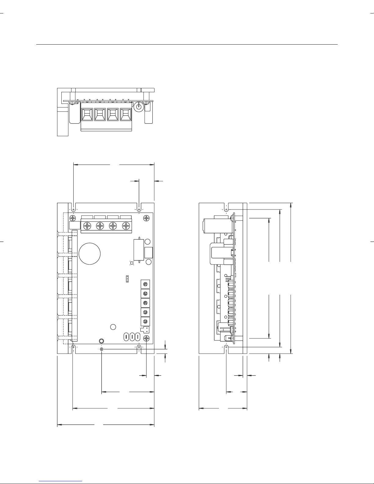
Figure 1. 175290.00 Dimensions . . . . . . . . . . . . . . . . . . . . . . . . . . . . . .2
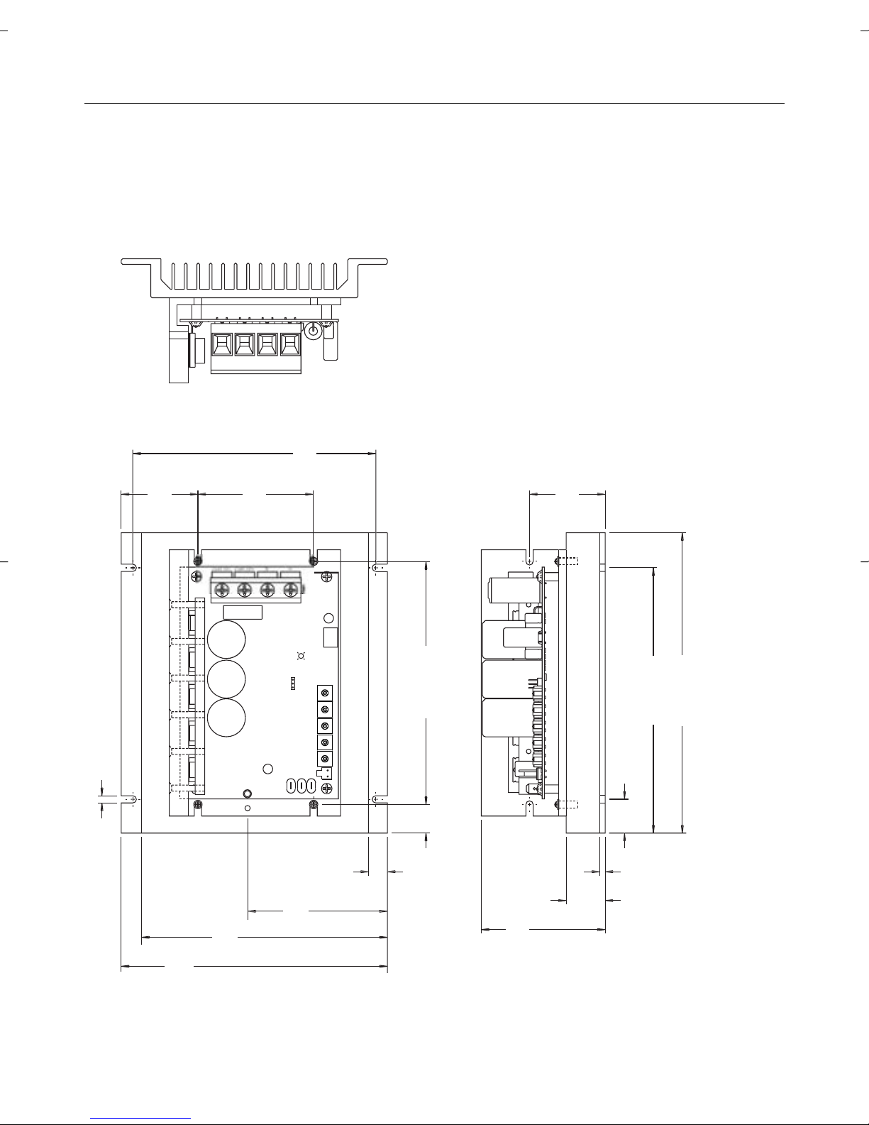
Figure 2. 175291.00 and 175292.00 Dimensions . . . . . . . . . . . . . . . . .3
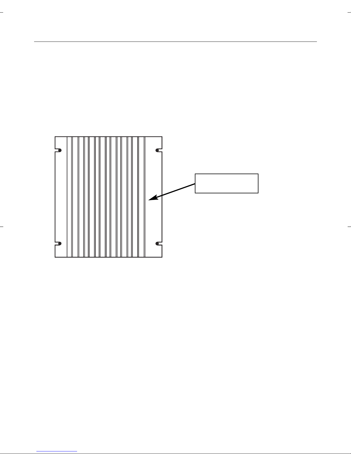
Figure 3. Heatsink mounting . . . . . . . . . . . . . . . . . . . . . . . . . . . . . . . . .7
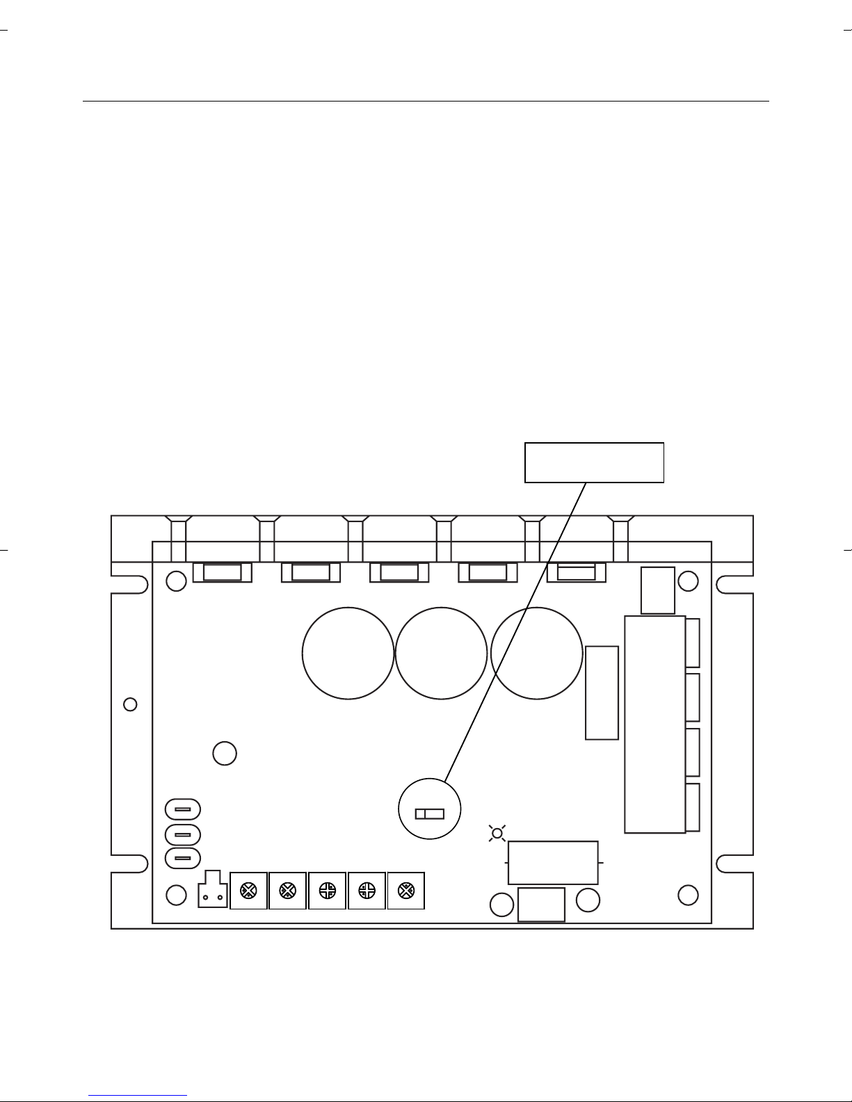
Figure 4. Jumper 501 (JP501) . . . . . . . . . . . . . . . . . . . . . . . . . . . . . . . .8
Figure 5. Speed Adjust Potentiometer . . . . . . . . . . . . . . . . . . . . . . . . .10
Figure 6. Speed Adjust Potentiometer Connections . . . . . . . . . . . . . .10
Figure 7. Power, Fuse and Motor Armature Connections . . . . . . . . . .13
Figure 8. Voltage Follower Connections . . . . . . . . . . . . . . . . . . . . . . .14
Figure 9. Run/Decelerate to Minimum Speed Switch . . . . . . . . . . . . .18
Figure 10. Inhibit Terminals . . . . . . . . . . . . . . . . . . . . . . . . . . . . . . . . .19
Figure 11. Power LED . . . . . . . . . . . . . . . . . . . . . . . . . . . . . . . . . . . . .20
Figure 12. Calibration Trimpot Layout . . . . . . . . . . . . . . . . . . . . . . . . .21
Figure 13. Approximate CUR LIMIT Settings . . . . . . . . . . . . . . . . . . . .26
Figure 14. Multiple Fixed Speeds . . . . . . . . . . . . . . . . . . . . . . . . . . . .27
Figure 15. Adjustable Fixed Speeds Using
Potentiometers in Series . . . . . . . . . . . . . . . . . . . . . . . . . .28
Figure 16. Independent Adjustable Speeds . . . . . . . . . . . . . . . . . . . . .29
Figure 17. RUN/JOG Switch Connection to
Speed Adjust Potentiometer . . . . . . . . . . . . . . . . . . . . . . . .30
Figure 18. Reversing hookup diagram . . . . . . . . . . . . . . . . . . . . . . . . .32
Tables
Table 1. Wire Gauge/Length Chart . . . . . . . . . . . . . . . . . . . . . . . . . . . .5

Max. Max.
Armature Armature DC Voltage
Current Voltage
3
Input Range
Model (Amps DC) (VDC) (VDC)
175290.00 16
1
12 or 24
2
10–32
175291.00 60 12 or 24
2
10–32
175292.00 60 36 or 48
2
32–50
Acceleration Time Range 0.5 – 10 seconds
Deceleration Time 0.5 seconds
Analog Input Range (signal common must be same as battery common) 0 – 10 VDC
Input Impedance (S1 to S2) 200KΩ
Speed Regulation (% of base speed) 1%
Speed Range 80:1
Form Factor 1.01
Ambient Operating Temperature Range 10°C – 40°C
Weight
175290.00 1.7 lbs.
175291.00 3.6 lbs.
175292.00 3.6 lbs.
1 At 40°C ambient. No additional heat sink is necessary.
2 Or up to 95% of available battery voltage.
3 The lower maximum armature voltage is selectable by connecting a jumper to
pins 2 and 3 of JP501 (see page 8).
Specifications
1
Dimensions
Figure 1. 175290.00 Dimensions
2
Q503 Q501 Q504 Q502
C504
C505
R502
C506
L501
SO501
IL501
TB501
C501
JP501
321
A2 +VDC INPUT -VDC INPUT
POWER
S3
S2
S1
INHIBIT
TIMIL RUCPMOC RIDPS NIM ACCEL MAX SPD
A1
0.70 [18]
0.70 [18]
2.20 [56]
0.95 [24]
0.19 [5]
6.90 [175]
6.30 [160]0.30 [8]
5.50 [140]
3.70 [94]
4.44 [113]
3.74 [95]
2.41 [61]
0.36 [9]
0.50 [13]
ALL DIMENSIONS IN
INCHES
[MILLIMETERS]
3
R501
1
2
7
C504
R502
503
50
1
504
L
501
502
POWER
7.78
[
198
]
.87
[
174
]
.88
[
22
]
1.01
[
26
]
.15
[
4
]
1.96
[
50
]
.21
[
82
]
.30
[
160
]
.30 [160]
.74 [19]
.19
[
5
]
.00
[
76
]
1.99
[
51
]
.90
[
175
]
.38 [162]
.49
[
12
]
.60
[
91
]
Figure 2. 175291.00 and 175292.00 Dimensions
ALL DIMENSIONS IN
INCHES
[MILLIMETERS]
Dimensions
SO501
JP501
321
S3S2S1
INHIBIT
TIMIL RUCPMOC RIDPS NIM ACCEL MAX SPD

4
• Drive components are sensitive to electrostatic fields. Avoid
contact with the circuit board directly. Hold drive by the chassis
only.
• Protect the drive from dirt, moisture, and accidental contact.
• Provide sufficient room for access to the terminal block and
calibration trimpots.
• Mount the drive away from other heat sources. Operate the drive
within the specified ambient operating temperature range.
• Prevent loose connections by avoiding excessive vibration of the
drive.
• Mount drive with its board in either a horizontal or vertical plane.
Six 0.19 in. (5 mm) wide slots in the chassis accept #8 pan head
screws. Fasten either the large base or the narrow flange of the
chassis to the subplate.
Mounting
Warning
Do not install, rewire, or remove this control with input
power applied. Doing so may cause fire or serious injury.
Make sure you have read and understood the Safety
Warnings on page i before attempting installation.
Installation

5
Installation
Use 18 AWG wire for speed adjust potentiometer wiring.
• Size the DC voltage input and motor wire according to the
following chart:
Table 1. Wire Gauge/Length Chart
Armature Current Wire Gauge Maximum Wire
(amps) (AWG) Length (feet)
0 – 19 14 8
20 – 32 10 10
60 8 10
Wiring
Warning
Do not install, remove, or rewire this equipment with power
applied. Failure to heed this warning may result in fire,
explosion, or serious injury.
This drive is isolated from earth ground. To prevent the
risk of injury or fatality, avoid direct contact with the printed
circuit board or with circuit elements.
Do not disconnect any of the motor leads from the drive
unless power is removed. Opening any one motor lead
may destroy the drive.
This drive is not diode-protected from reverse battery
voltage. You must assure that POS (+) is wired to +VDC
IN and NEG (–) is wired to –VDC IN.

6
Installation
Shielding guidelines
As a general rule, LEESON recommends shielding of all
conductors.
If it is not practical to shield power conductors, LEESON
recommends shielding all logic-level leads. If shielding of logic level
leads is not practical, the user should twist all logic leads with
themselves to minimize induced noise.
It may be necessary to earth ground the shielded cable. If noise is
produced by devices other than the drive, ground the shield at the
drive end. If noise is generated by a device on the drive, ground
the shield at the end away from the drive. Do not ground both ends
of the shield.
If the drive continues to pick up noise after grounding the shield
mount the drive in a less noisy environment.
Logic wires from other input devices, such as motion controllers
and PLL velocity controllers, must be separated from power lines in
the same manner as the logic I/O on this drive.
Warning
Under no circumstances should power and logic leads be
bundled together. Induced voltage can cause unpredictable
behavior in any electronic device, including motor controls.
7
Heat sinking
175291.00 and 175292.00 drives are pre-mounted on a heat sink.
For optimum heat transfer, mount the drive with heatsink fins
standing vertically as shown in Figure 3 below.
Fuse / Circuit breaker protection
All LEESON drives should be protected by a fuse or circuit breaker.
Use a fast acting fuse or circuit breaker rated for approximately
200% of the maximum armature current and armature voltage.
Connect the fuse or circuit breaker to the VDC+ IN side of the DC
voltage input.
Installation
Figure 3. Heatsink mounting
Heatsink Fins
8
Installation
A1
A2
+VDC INPUT
-VDC INPUT
R502
C506
INHIBIT
SO501
C504
C505
L501
D501
Q503 Q501
Q504
R501
IL501
Q502
TB501
C501
C502
C507
R503
JP501
321
POWER
S3
S2
S1
TIMIL RUCPMOC RIDPS NIM ACCEL MAX SPD
Figure 4. Jumper 501 (JP501)
Jumper 501
Jumper 501 (JP501)
LEESON 17529X.00 series drives are shipped with pins 1 and 2
jumpered on JP501. This allows you to use 24 VDC motors with
the 175290.00 and 175291.00, or 48 VDC motors with the
175292.00. To use lower voltage DC motors (12 VDC or 36 VDC,
respectively) jumper pins 2 and 3 with the jumper provided. See
Figure 4 for the location of JP501.
175290.00 = 16 Amp 12/24 VDC
175291.00 = 60 Amp 12/24 VDC
175292.00 = 60 Amp 36/48 VDC
 Loading...