

Page 1
MODEL 174694.00/174695.00 Rev.A HOOK-UP
S
O
WARNING
IMPROPER INSTALLATION OR OPERATION OF THIS CONTROL MAY RESULT IN INJURY TO PERSONNEL OR ELECTRONIC FAILURE. THE
CONTROL MUST BE INSTALLED AND GROUNDED IN ACCORDANCE WITH LOCAL, STATE, AND NATIONAL SAFETY CODES. AT NO TIME
SHO ULD THE CIRCUIT CONTI NUITY BE CHE CKE D BY S HORT ING TERM INALS WITH A SCRE WDRIVE R OR O THE R METAL DE VI CE.
PLEASE READ COMPLETELY BEFORE MAKING ANY ADJUSTMENTS
HOOK-UP & TERMINAL IDENTIFICATION
1) Before attempting to wire the control' make sure all power is turned off.
2) Use a normal blow fuse' wired in series with hot side of AC input' rated to 125% of motor current. Note: Both
AC lines should be fused for 240 VAC input.
CAUTION SHOULD BE USED IN SELECTING THE SIZE OF HOOK-UP WIRING. LIMIT THE VOLTAGE DRO P THROUGH THE WIRING TO 5% OF
THE LINE VOLTAGE AT FULL LOAD.
3) +ARM: Connect to plus (+) Armature wire on motor. 0-90 VDC for 120 VAC input' and 0-180 VDC for 240 VAC input.
4) -ARM: Connect to minus (-) Armature wire on motor.
5) -FIELD: Connect to minus (-) Field wire of Shunt Wound Motor.
6) AC1 and AC2: 120 VAC - Connect incoming hot AC (black wire) to AC 1 and neutral (white wire) to AC2
240 VAC - Connect both hot sides' one to AC1 and one to AC2.
7) +FIELD: Do not use for permanent magnet motor. This supplies +Field voltage for a Shunt Wound Motor. For motors
with dual voltage field (ie; 50/100V or 100/200V)' make sure the highest value is connected.
CAUTION: DO NOT ATTEMPT TO PERFORM A HI-POT TEST ACROSS AC LINES WITH CONTROL IN CIRCUIT.
THIS WILL RESULT IN IMMEDIATE OR LONG TERM DAMAGE TO THE CONTROL.
ADJUSTMENTS
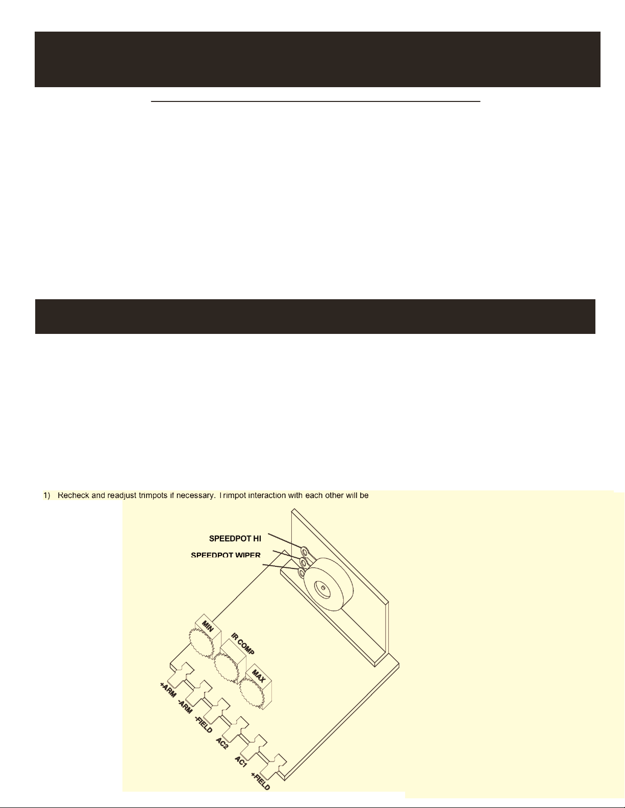
1) Preset trimpots in the counter-clockwise (CCW) position.
2) Apply power.
3) Rotate the Speedpot fully CW and adjust MAX trimpot in the CW direction until the maximum desired
speed is obtained.
4) Rotate the Speedpot fully counter-clockwise (CCW) and adjust the MIN trimpot in the CW
direction until deadband or the minimum desired speed is obtained.
5) The IR COMP trimpot is used as a regulation adjustment. If better motor regulation is needed between minimum and maximum loads' then
adjust IR COMP trimpot as follows. Rotate the Speedpot CW to the 50% position and rotate the IR COMP trimpot CW as needed to increase
regulation.
1) Recheck and readjust trimpots if necessary. Trimpot interaction with each other will be
SPEEDPOT HI
PEEDPOT L
Page 2
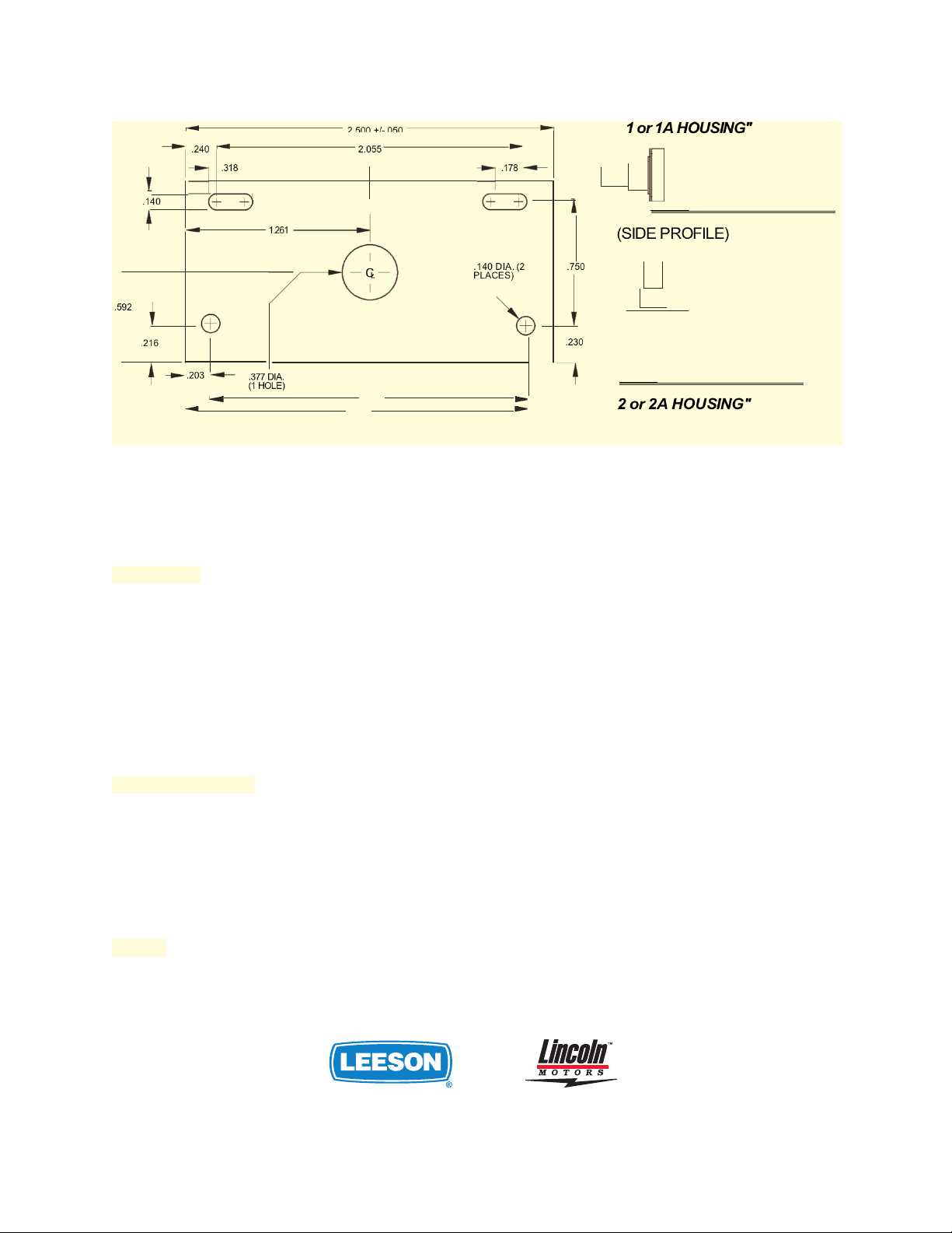
HEATSINK DIMENSIONS & IDENTIFICATION
.592
.140
.216
.240
.203
.318
1.261
.377 DIA.
(1 HOLE)
-
2.055
C
L
2.126
2.326
.178
.140 DIA. (2
PLACES)
.750
.230
174694.00/174695.00 Rev.A MODEL SPECIFICATIONS
1 or 1A HOUSING"
(SIDE PROFILE)
2 or 2A HOUSING"
AC Input Voltage ............................................................... ................................. ± 10% Rated Line Voltage
Amps- DC Output ............................................................................................................ 150mA to 2 Amps
Dimensions ........................................ ............................... 174694.00: 2.80" wide, 1.30" high, 3.30" deep
Dimensions
....................................................................... 174695.00: 2.80" wide, 1.50" high, 3.30" deep
Input Frequency ...................................................................................... ............................... 50160 Hertz
Input Voltage - .................................................................. ........................................... 120 VAC or 240 VAC
I.R. Compensation .................................................................. ................................ Adjustable -full range
Max. Speed ...................................................... ............................... Adjustable (40 -120% of Base Speed)
Min. Speed ..................................................................... ................................ Adjustable (0 - 30% of Max)
Output Voltage ...................................................................................................................... 0-105 or 0-210 VDC
Overload Capacity ........................................................................... ............................... 200% for 1 minute
Shunt Field Voltage ................................................. ............................... 1 Amp max, 100 VDC at 120 VAC
Shunt Field Voltag
................................................... ............................... 1 Amp max, 200 VDC at 240 VAC
Speed Control .............................................................. ............................... 5K Ohm Speed Potentiometer
Speed Range ......................................................................................................................................... 25:1
Speed Regulation ....................................................................... ................................. ± 1% of Base Speed
Temperature Range .......................................... ............................... -100 to 450 C. Ambient (150 to 1150 F.)
Transient
Protection ..........................................................................................................................................G-Mov
Weight ................................................................... .............. ............................... 174694.00 weighs 2.64 oz.
Weight
................................................................................. ............................... 174695.00 weighs 3.03 oz.
With suitable external heatsink, current can be increased to 4 Amps. The control’s heatsink temperature
should not exceed 70° C. Equivalent to 4" x 4" x 0.125" thick aluminum plate mounted to housing.
GRAFTON, WISCONSIN 53024-0241 U.S.A.
TEL. (262) 377-8810 FAX (262) 377-9025
www.leeson.com
 Loading...