

Page 1
Tools required for installation and servicing:
3/8” hex wrench 5/16” nut driver 5/16” hex wrench Torque wrench
1/4” screwdriver 3/16” hex wrench 8” adjustable wrench
Installation and Service Instructions
for 56/143-5TC Double C-Face Coupler
Important
Please read these instructions carefully
before installing, operating, or servicing
your brake. Failure to comply with these
instructions could cause injury to personnel
and/or damage to property if the brake is
installed or operated incorrectly. For definition of limited warranty/liability, contact
Leeson Electric Corporation, P.O. Box 241,
2100 Washington Street, Grafton, WI
53024-0241, (262) 377-8810.
Caution
1. Installation and servicing must be made
in compliance with all local safety codes
including Occupational Safety and
Health Act (OSHA). All wiring and electrical connections must comply with the
National Electric Code (NEC) and local
electric codes in effect.
2. Do not operate the brake in
atmospheres containing explosive
gases or dusts.
3. To prevent an electrical hazard, disconnect power source before working on
the brake. If power disconnect point is
out of sight, lock disconnect in the off
position and tag to prevent accidental
application of power.
4. Make certain power source conforms to
the requirements specified on the brake
nameplate.
5. Be careful when touching the exterior of
an operating brake. Allow sufficient time
for brake to cool before disassembly.
Surfaces may be hot enough to be
painful or cause injury.
6. Do not operate brake with housing
removed. All moving parts should be
guarded.
7. Installation and servicing should be performed only by qualified personnel
familiar with the construction and operation of the brake.
8. For proper performance and operation,
only genuine Stearns parts should be
used for repairs and replacements.
9. After usage, the brake interior will contain burnt and degraded friction material
dust. This dust must be removed before
servicing or adjusting the brake.
DO NOT BLOW OFF DUST using an air
hose. It is important to avoid dispersing
dust into the air or inhaling it, as this may
be dangerous to your health.
a) Wear a filtered mask or a respirator
while removing dust from the inside of a
brake.
b) Use a vacuum cleaner or a soft brush
to remove dust from the brake. When
brushing, avoid causing the dust to
become airborne. Collect the dust in a
container, such as a bag, which can be
sealed off.
10. Caution! While the brake is equipped
with a manual release to allow manual
shaft rotation, the motor should not be
run with the manual release engaged, to
avoid overheating the friction disc(s).
Warning! Do not apply overhung or side
load to brake output shaft
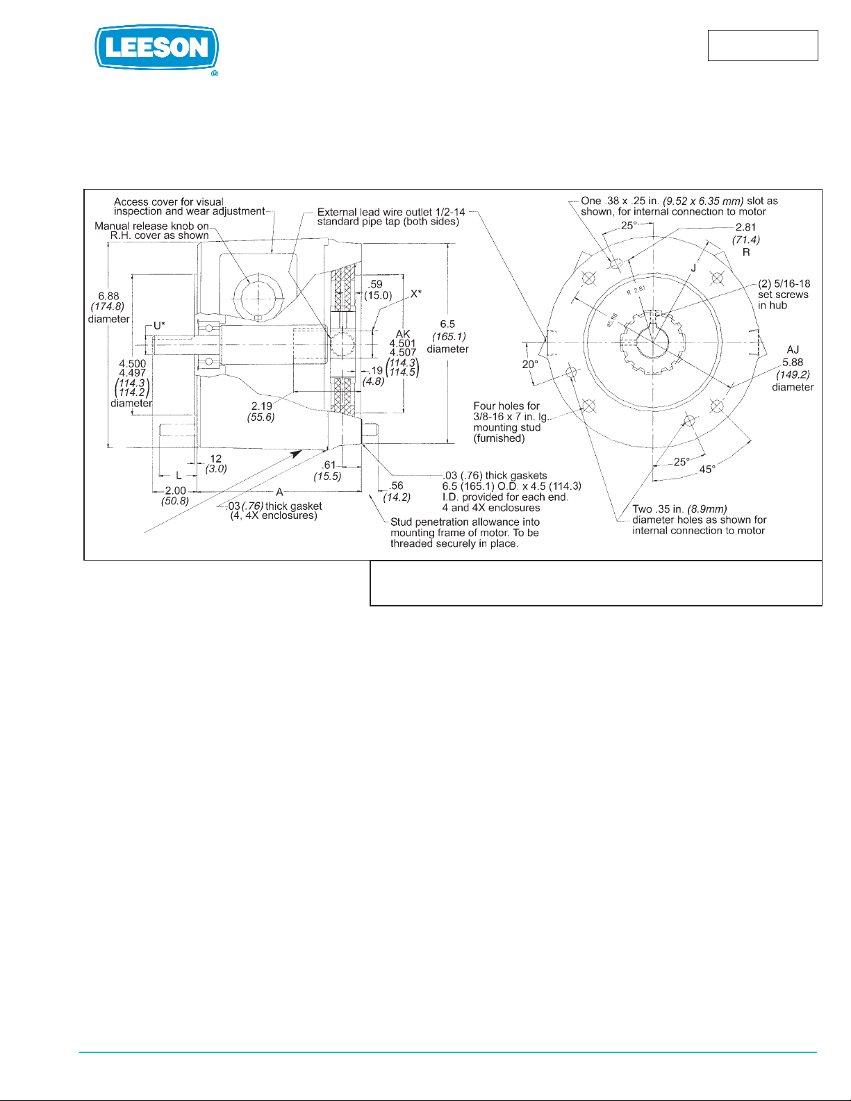
General Description
The 56,700 Series coupler is a spring-set,
electrically released brake, containing either
one or more rotating friction discs (4) driven
by a hub (16) mounted on the motor shaft.
The double C-face allows the brake to directly
couple a C-face motor to a C-face gear
reducer.
Figure 1
(See Page 4
For replacement parts refer to sheet
part number 8-078-906-07.
Instructions and parts list also available at www.rexnord.com/stearns.
ELECTRIC MOTORS
GEARMOTORS AND DRIVES
P/N 8-078-905-68
effective 03/25/2005
LEESON ELECTRIC P.O. BOX 241 2100 Washington Street Grafton, WI 53024-0241 U.S.A
A Subsidiary of Regal-Beloit Corporation
Drain Plug
(WASHGUARD brakes only)
Page 2
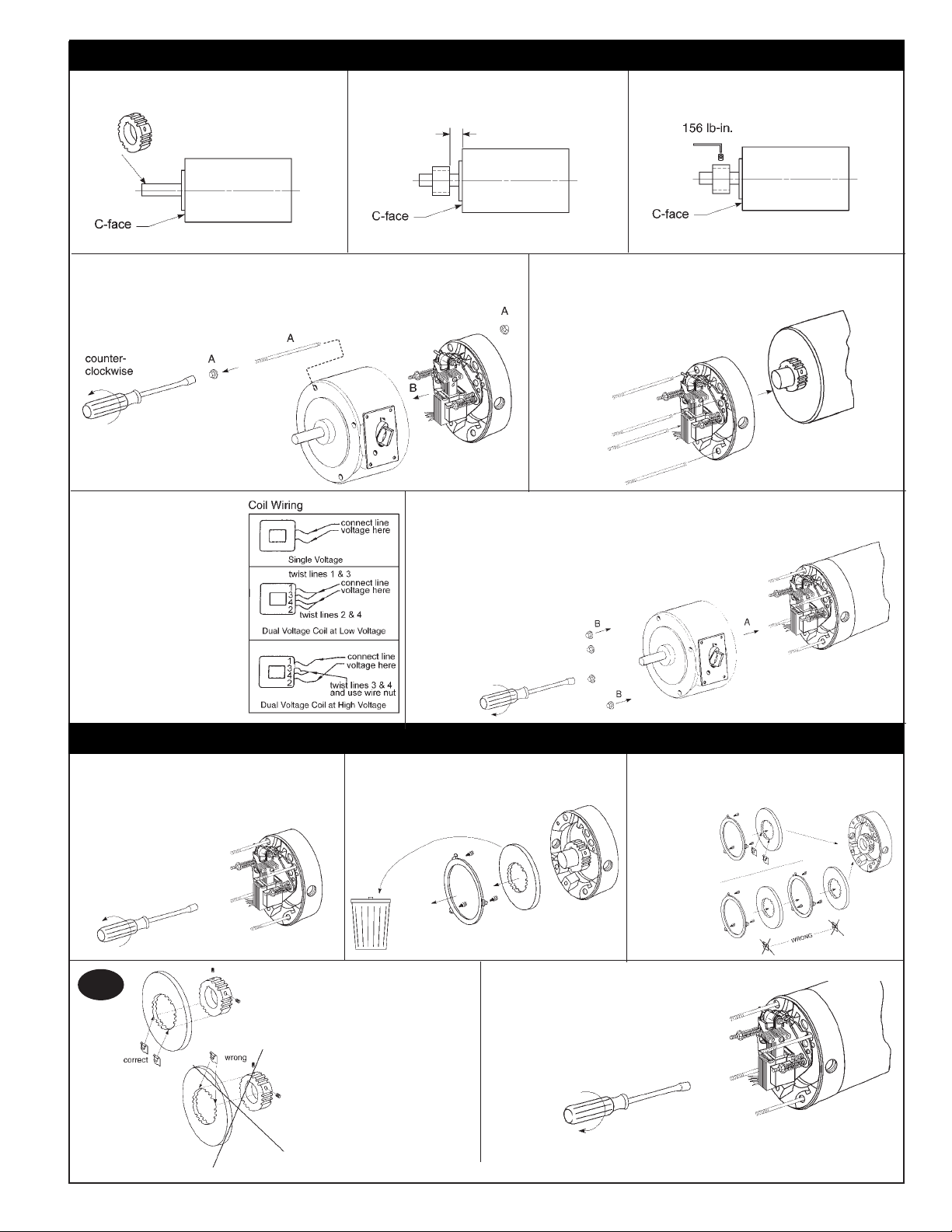
Position hub on shaft as shown.
Place hub on motor shaft.
Tighten set screws to motor shaft.
Connect coil leadwires to power
supply. Refer to
nameplate for
voltage rating.*
Caution: Keep
wiring away from
pinch points and
moving components.
.188”
(4.77mm)
BRAKE MOUNTING (Manual Adjust)
* Stabilizer clips
are for use on
single disc units
only. Position
clips opposite
set screw holes.
3A
Remove support plate screws and
lift support from brake
Reposition support plate on endplate and
tighten mounting screws to 55 lb-in.
Install new friction disc(s) and
stationary disc(s) as shown.
Remove and discard old friction disc.
clockwise
For brakes
with vertical
springs see
Vertical
Spring
Assembly
Section.
FRICTION DISC REPLACEMENT SERIES
2
Note: Friction discs can wear to 1/2 their original thickness, or .093”
A. Remove housing nuts and slide tie bolt out of brake.
B. Remove housing from endplate.
Slide endplate over hub noting position of stabilizer
clips, if used. (Refer to Friction Disc Replacement
view 3 and 3A). Mount brake endplate to
motor C-face using the four tie bolts.
Finger tighten.
A. Slide housing and shaft assembly onto mounting studs, rotating
shaft until keyway is aligned. Be sure housing is assembled with
access windows in same position as shown in Figure 1, page 1.
B. Mount and secure brake/motor assembly to
C-face mounting register of reducer.
Using four 3/8 - 16 nuts and
lockwashers, tighten to 30-35 ft-lb.
clockwise
counter-
clockwise
Page 3

Lift plunger/solenoid
lever assembly
out of coil.
Remove plunger guide.
A) Re-insert plunger into coil; drop
pivot pin into cradle of support plate.
B) Remove screwdriver.
A) Insert new coil.
(Lead wires in same
position as old coil.)
B) Insert plunger guide.
Insert screwdriver
between support
plate and lever
arm and pry
forward.
A
B
A
B
Remove housing and disconnect power and wiring to coil.
Discard coil.
Vertical Brake Assembly
Single disc brakes (3 & 6 lb-ft) are universal
mount and do not require separator springs.
Double disc brakes (10-15 lb-ft.) are universal
mount but require separator springs which are
preassembled to the stationary disc. These
discs are inserted spring first into the brake.
Refer to figure 2A.
Reconnect coil and replace housing per installation instructions, page 2.
3
To increase air gap, turn both adjusting
screws (10) counterclockwise.
To decrease air gap, turn both adjusting
screws (10) clockwise.
As friction disc wear the air gap will increase. When plunger gets to the reset position, the air gap must be adjusted.
counter-clockwise
clockwise
Torque
Torque (lb-ft) 56,X00 Series
3 & 6 .38” ± .03”
10 & 15 .45” ± .03”
Air Gap Settings*
*For reference only
AIR GAP ADJUSTMENT
VERTICAL SPRING ASSEMBLY
COIL REPLACEMENT SERIES
Note: Air gap can be adjusted witout disassembly. Remove cover
plate (7A) and manual release plate (7B) and adjust as shown above.
7A
7B
Maximum gap should never exceed .80”.
Torque Adjustment
Brake is factory set for nominal rated static
torque which is maximum torque. Torque may be
decreased up to 50% for increased stopping
times up to 2 second stop time.
Turn both spring adjustment screws (11), Figure
3, equal amounts counterclockwise to decrease
torque. See Table A for torque reduction permissible amounts.
Nominal Original Maximum % Torque
Static Spring Counter- Reduction
Torque Height clockwise per
(lb-ft) (inches) Turns Turn
3 1.50”
6 1.50”
10 1.56”
15 1.56”
Figure 3
Table A
Figure 2A
TORQUE ADJUSTMENT
11
10
10
11
5-1/2 9%
Page 4

Torque
lb. ft.
Leeson
Part
Number
Stearns
Part
Number
Brake Coil
Rating (VAC)
NEMA
Enclosure
Brake Bore/
Shaft Diameter
(X/U)
NEMA
Frame Size
Dimension
A
3
175563.00 1056711051PF 115/208-230 2 5/8” / 5/8” 56C 4.91”
175564.00 1056711051QF 208-230/460 2 5/8” / 5/8” 56C 4.91”
175565.00 1056711051NF 575 2 5/8” / 5/8” 56C 4.91”
175566.00 1056714051PF 115/208-230 4X 5/8” / 5/8” 56C 4.94”
175567.00 1056714051QF 208-230/460 4X 5/8” / 5/8” 56C 4.94”
175568.00 1056714051NF 575 4X 5/8” / 5/8” 56C 4.94”
6
175569.00 1056721081PF 115/208-230 2 7/8” / 5/8” 56C/143-5TC 4.91”
175570.00 1056721081QF 208-230/460 2 7/8” / 5/8” 56C/143-5TC 4.91”
175571.00 1056721081NF 575 2 7/8” / 5/8” 56C/143-5TC 4.91”
175572.00 1056724081PF 115/208-230 4X 7/8” / 5/8” 56C/143-5TC 4.94”
175573.00 1056724081QF 208-230/460 4X 7/8” / 5/8” 56C/143-5TC 4.94”
175574.00 1056724081NF 575 4X 7/8” / 5/8” 56C/143-5TC 4.94”
10
175575.00 1056731081PF 115/208-230 2 7/8” / 5/8” 56C/143-5TC 4.91”
175576.00 1056731081QF 208-230/460 2 7/8” / 5/8” 56C/143-5TC 4.91”
175577.00 1056731081NF 575 2 7/8” / 5/8” 56C/143-5TC 4.91”
175578.00 1056734081PF 115/208-230 4X 7/8” / 5/8” 56C/143-5TC 4.94”
175579.00 1056734081QF 208-230/460 4X 7/8” / 5/8” 56C/143-5TC 4.94”
175580.00 1056734081NF 575 4X 7/8” / 5/8” 56C/143-5TC 4.94”
15
175581.00 1056741071QF 208-230/460 2 7/8” / 7/8” 143-5TC 4.91”
175582.00 1056744071QF 208-230/460 4X 7/8” / 7/8” 143-5TC 4.94”
PART NUMBERS
COIL FAILURE
SUPPLY VOLTAGE CAUSE SUPPLY VOLTAGE CORRECTION
Line voltage >110% of coil rating Reduce voltage or replace with
proper rated coil
Excessive voltage drop during inrush time Increase current rating of power supply.
WIRING CAUSE WIRING CORRECTION
Leadwires interfering with plunger pull-in
Reroute wiring away from plunger and
other moving components.
Excessive voltage drop during inrush time Increase leadwires size from power supply
Coil leadwire shorted to ground Replace coil or leadwire and protect with
wire sleeving
SOLENOID ASSEMBLY CAUSE
SOLENOID ASSEMBLY
CORRECTION
Plunger not seating flush against
solenoid frame
Loosen solenoid mounting screws and
reposition frame to allow full face contact
Plunger cocked in coil preventing pull-in Realign solenoid frame
Excessive solenoid/plunger wear at
mating surface
Replace solenoid assembly
Broken shading coils Replace solenoid assembly
WORN PARTS CAUSE WORN PARTS CORRECTION
Excessive wear of solenoid link arm
and/or shoulder bolt
Replace link arm and link bolt; also
inspect plunger thru-hole for elongation
Plunger guides worn down and interfering
with plunger movement
Replace guides
APPLICATION CAUSE APPLICATION CORRECTION
Machinery cycle rate is exceeding brake
rating
Reduce brake cycle rate or use
alternate control method
High ambient temperature (>110%) and
thermal load exceeding coil insulation
rating
Use Class H rated coil and /or find
alternate method of cooling brake
Brake coil wired with windings of an
Inverter motor or other voltage/current
limiting device
Wire coil to dedicated power source with
instantaneous coil rated voltage
MISCELLANEOUS CAUSE MISCELLANEOUS CORRECTION
Wrong or over tightened torque Replace with proper spring or refer to
Installation section for proper spring height
Excessive air gap Reset, refer to Installation Section 4
EXCESSIVE WEAR / OVERHEATING
AIR GAP CAUSE AIR GAP CORRECTION
Low solenoid air gap Reset air gap (refer to Air Gap
Adjustment)
Disc pack dragging Inspect endplate, hub and discs for dirt,
burrs, wiring and other sources of interference preventing disc “float”
CYCLE RATE CAUSE CYCLE RATE CORRECTION
Brake “jogging” exceeding coil cycle rate Reduce cycle rate or consider
alternate control method
Thermal capacity is being exceeded Reduce cycle rate, use alternate control
method or increase brake size
ALIGNMENT CAUSE ALIGNMENT CORRECTION
Broke endplate not concentric to motor
C-Face
Motor register must be within .004” on
concentricity;
Motor shaft runout is excessive Must be within .002”; runout; consult
motor manufacturer
Brake is being operated on a incline
greater than 15° above or below
horizontal
Vertical separator springs must be used to
prevent discs from becoming cocked
WORN PARTS CAUSE WORN PARTS CORRECTION
Friction disc excessively worn (disc can
wear to 1/2 original thickness or .093”)
Replace friction discs.
Endplate, stationary disc or pressure
plate warped
Replace warped or worn component
Linkages and/or pivot pins worn Replace all worn components
Motor shaft endfloat excessive Endfloat must not exceed .020”;
consult motor manufacturer
HUB CAUSE HUB CORRECTION
Burr on hub interfering with disc “float” File off burr
Set screw backed out and interfering with
disc
Retighten set screw; use Loctite® 242 to
help secure
MISCELLANEOUS MISCELLANEOUS
Solenoid plunger not pulling completely Check line voltage (±10% of
nameplate rating) or replace worn
solenoid assembly
Wiring is restricting disc pack movement Reroute wiring
Excessive stop time
(2 seconds or greater)
Increase brake size/torque or use alternate control method
High Ambient temperature
(in excess of 110°F)
Reduce cycle rate or use alternate
method of cooling
Moisture in brake
Remove drain plug (WASHGUARD
brakes only). After fluid has drained
replace plug
TROUBLESHOOTING
4
 Loading...