

Page 1

Leer, Inc.
206 Leer Street, P.O. Box 206
New Lisbon, WI 53950
1-800-766-5337
www.leerinc.com
Vending Machine
INSTALLATION, OPERATION, AND SERVICE
MANUAL
Scan here to be taken to the Leer Support / Vending Installation page.
Form # 1070019 01/17
Page 2

Table of Contents
Storage and Unpacking ............................................................................................................................. 3
Storage: ............................................................................................................................................................... 3
Unpacking: .......................................................................................................................................................... 3
Vending Machine Pallet Removal: ..................................................................................................................... 3
Set-up Prior to Installing at Retail Location: ...................................................................................................... 4
Reporting Provision Code: .................................................................................................................................. 4
Door Locks and Sensors ..................................................................................................................................... 4
Calibrate Scale: ................................................................................................................................................... 4
Test Transactions: ............................................................................................................................................... 5
Electrical Supply: ................................................................................................................................................ 5
Condensate Evaporator Pan ................................................................................................................................ 6
Start-up the Vending Machine at Retail Location: ............................................................................................. 6
Door Locks and Sensors: .................................................................................................................................... 6
Calibrate Scale Before Loading Ice: ................................................................................................................... 6
Test Transactions: ............................................................................................................................................... 6
Loading Ice ......................................................................................................................................................... 7
Stocking Instructions: ......................................................................................................................................... 7
Operating Mode Display: .................................................................................................................................... 7
Possible Displayed Alarm Codes: ....................................................................................................................... 8
Maintenance .................................................................................................................................................... 8
General: ............................................................................................................................................................... 8
Cleaning Condenser Coils: ................................................................................................................................. 8
Defrosting: .......................................................................................................................................................... 9
Cleaning the Vending Machine: ......................................................................................................................... 9
Vending Machine Door Maintenance: ................................................................................................................ 9
Vending Calibration: ........................................................................................................................................... 9
Replacement Parts:.............................................................................................................................................. 9
Part Returns:........................................................................................................................................................ 9
Wiring Diagram ............................................................................................................................................. 10
Refrigeration Trouble Shooting Table .............................................................................................. 11
Vending Trouble Shooting Table......................................................................................................... 12
Warranty ........................................................................................................................................................... 13
[2]
Page 3
Storage and Unpacking
Storage:
The Vending Machine should be stored and
transported in an upright position. If the Vending
Machine is tilted beyond 45 degrees of vertical, oil
may drain from the compressor casing. Should this
occur, it’s recommended that the Vending Machine
be returned to a vertical position for at least 1 hour
before energizing the unit. This will allow oil that
may have migrated out of the casing an opportunity
to drain back to the compressor.
Unpacking:
Prior to installation, the outer packaging on the
Vending Machine will need to be removed. The
majority of the packaging materials can be recycled
and disposed of in an environmentally friendly
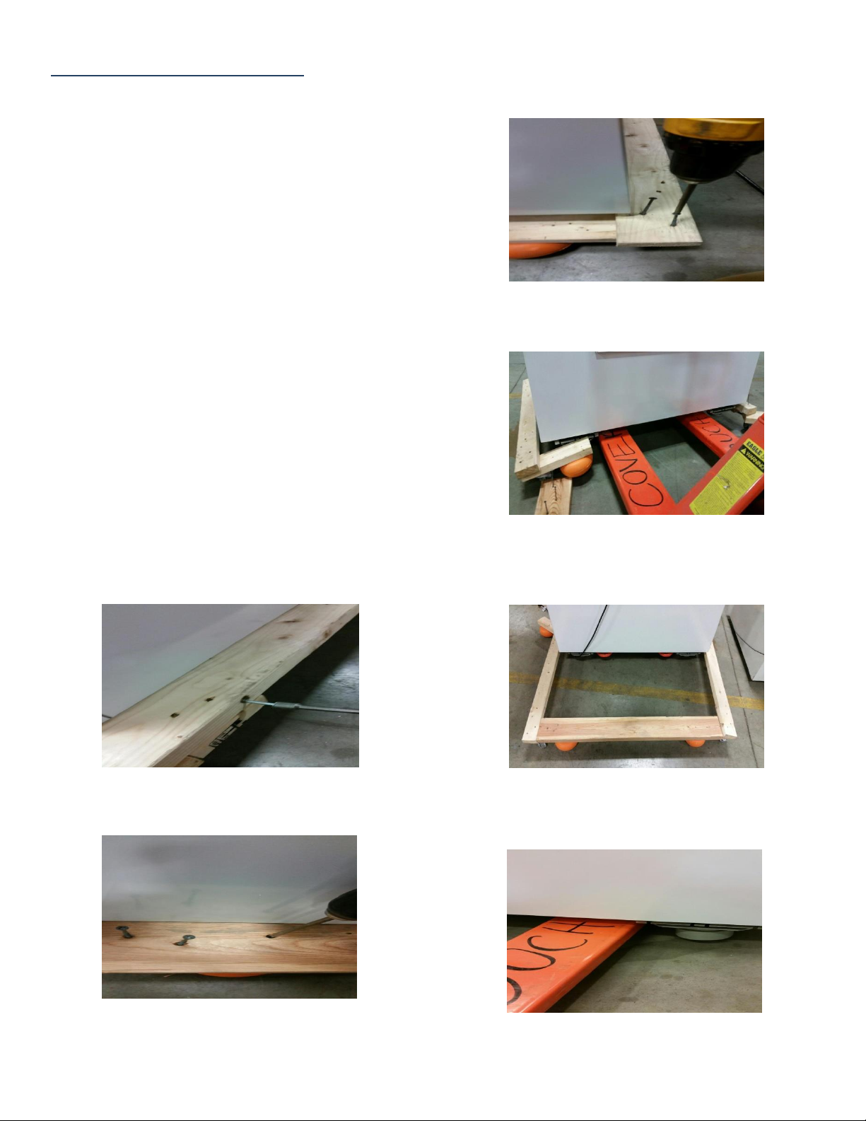
manner. The wooden skid is secured to the
Vending Machine with hex-headed screws and will
require the use of a 3/8" hex-socket for screw
removal.
3. Remove two Philips screws from the left or
right side. This will remove the skid footing
to aid in use of pallet jack.
4. Insert pallet jack from the front side.
CAUTION: Stay clear of the load cells.
Vending Machine Pallet Removal:
1. First remove two screws from each side
perimeter board using a long 3/8” hexsocket.
2. Remove the six Philips screws from the
front perimeter board and remove board.
5. Use lifting device to lift the unit high
enough to remove pallet and the orange
pallet cushions from the back.
6. Slide unit off of the pallet jack into position
on a sturdy level surface. Use stackers
included if needed.
[3]
Page 4
Start-Up
Set-up Prior to Installing at Retail
Location:
The Vending Machine refrigeration system will
arrive at the customer location ready to operate
within design parameters that have been tested and
deemed optimum for ice storage.
Prior to installing the Vending Machine at the retail
location, perform a series of steps for set up and
checks to ensure the unit was not damaged during
delivery. NOTE: The pallet and all packaging
material must be removed before proceeding.
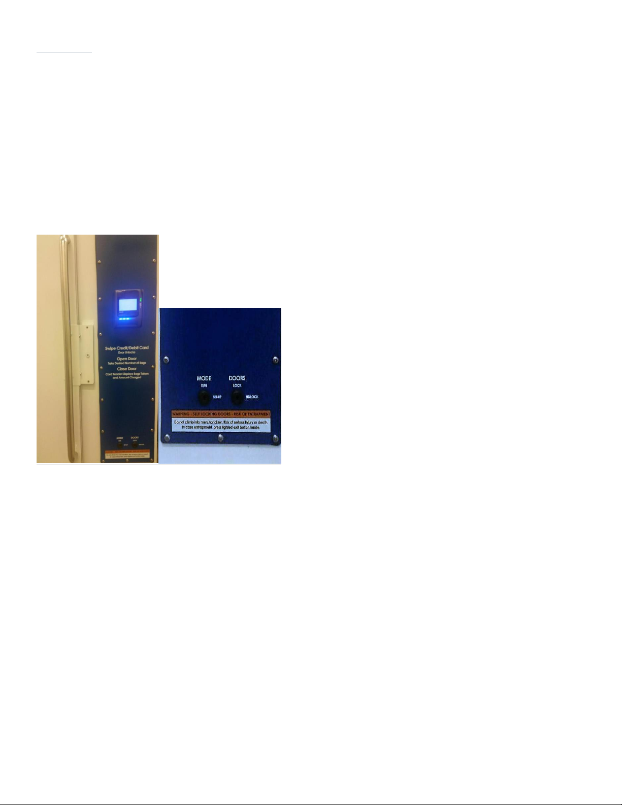
1. Prior to energizing the Vending Machine, place
the MODE key in the ‘RUN’ position and the
DOORS key in the ‘LOCK’ position.
Failure to place the MODE key in the
‘RUN’ position prior to energizing will
result in a blank screen on the card
reader.
2. Energize the Vending Machine and let it run for
about 1 hour.
Within a few seconds of being plugged
in, the compressor and condenser fan
motor will energize.
o NOTE: If the unit does not start
within a few seconds, check the
on/off switch located next to the
electronic control display.
The Vending Machine will continue to
run until it has reached the factory preset cut-out temperature of +16 degrees F.
Reporting Provision Code:
3. At start-up, watch for and record the provision
code to be displayed on the card reader. Report
the provision code to Vendnovation by calling
425-637-2344.
Vendnovation will provision the Vending
Machine and update firmware if needed.
Vendnovation will assign product and link
to test credit card system.
Door Locks and Sensors
After the unit has been running for 1 hour, the doors
can now be tested.
4. Check the doors – they should be locked.
5. Turn the MODE key to the ‘SET-UP’ position.
“Synchronize Inventory” will display
6. Press cancel button once
“Hardware” will display
7. Press enter button once
“Test Door“ will display
8. Press enter button once
The doors will unlock and “Door Closed”
If it showing “Door Open” the door sensors
need to be adjusted.
9. Open and close each door
As each door is opened and closed the
display should show “Door Open” or “Door
Closed”
10. Press cancel button once
The doors will lock again
11. Return the MODE key to the ‘RUN’ position.
Calibrate Scale:
12. Turn the MODE key to the ‘SET-UP’ position.
“Synchronize Inventory” will display
13. Press cancel button once
“Hardware” will display
14. Press cancel button three times
“Calibrate Scale“ will display
15. Press enter button once
[4]
Page 5
System will calibrate and should display “0”
16. Return the MODE key to the ‘RUN’ position.
Test Transactions:
17. Load a few bags of ice in the Vending Machine.
18. Verify that the displays correct bag size and
price is displayed.
19. Perform a test transaction and verify the
transaction processed successfully.
20. Contact Vendnovation and have the Vending
Machine unit linked to live credit card account.
Call 425-637-2344
End of Vending Setup Instructions
Installation Location:
When placing the Vending Machine, there should
be a minimum of 3 inches of air space between all
sides of the cabinet and any surrounding structures.
This air space allows for air flow over the surface of
the cabinet, thus reducing condensation and aid in
the drying of these surfaces. The 3 inch space
behind the Vending Machine will also help ensure
that the evaporator drain tube, which exits the back
wall, is not being restricted or blocked during the
defrost cycle.
Locate the Vending Machine so that the main power
cord is within reach of an electrical outlet.
WARNING: DO NOT use extension cords as they
decrease the voltage to the unit and ultimately cause
compressor failure.
Outdoor Vending locations shaded from sunlight
are recommended for more economical operation.
The Vending Machine should be located on a solid
level base and must be level to operate properly. If
the Vending Machine is exhibiting a slight forward
lean, the front of the cabinet should be blocked to
bring the cabinet to a level position. A unit that is
not level could result in ice buildup due to improper
water drainage during the defrost cycle.
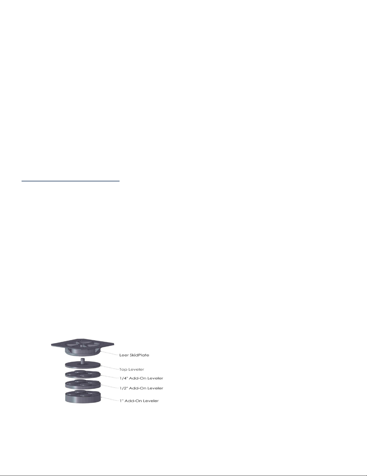
In vending units, improper leveling may cause
inaccurate weight measurements. Contact on any
part of the Vending Machine other than the skid
plates and/or leveling kits will result in inaccurate
weight measurement.
Leveling Kits No. 1050019, are included
and must be installed by customer to qualify
for NSF approval.
The installation location must also provide good air
flow for the designed refrigeration system to
operate efficiently. WARNING: DO NOT block
the refrigeration grill openings. Grill blockage may
result in compressor failure.
Electrical Supply:
NOTE: Electrical and refrigeration repair work
should be done by licensed professionals.
The Vending Machine must be plugged into a 115
volt, 60 Hz grounded electrical outlet with a circuit
fuse or breaker rated at a minimum of 15 Amps.
The electrical service connections to the Vending
Machine must be a dedicated line and compliant
with national electric code and local codes that may
apply. DO NOT use extension cords. Some models
are equipped with a main power switch. If so
equipped, make sure the switch is in the OFF
position before plugging the merchandiser into the
outlet. Plug the merchandiser power cord into the
lower receptacle of the electrical outlet. Turn the
switch if equipped into the ON position. After a few
seconds delay, the compressor and the condenser
fans should start. The evaporator fan motors and the
light fixture should start immediately when power is
applied. The condensing unit will continue to run
until the air temperature in the cabinet reaches +16
degrees F.
WARNING: Operating more than one appliance on
the same circuit may result in voltage fluctuations
when both appliances are operating simultaneously.
This voltage fluctuation may lead to premature
compressor failure.
Information regarding the electrical voltage and
frequency being supplied to the Vending Machine
can be found on the Vending Machine’s serial data
plate typically located at the upper left hand corner
[5]
Page 6

of the Vending Machine’s interior. Information
regarding the maximum fuse/circuit breaker size
required for the specific Vending Machine model is
available from the condensing unit data plate.
Condensate Evaporator Pan
If the Vending Machine has a condensate
evaporator, remove from inside merchandiser and
install evaporator on back of unit per instruction
sheet inside carton then plug the cord into the upper
receptacle of the electrical outlet and the heater rod
will begin to heat. The unit must be placed so that
there is at least 1 inch of air space between the back
surface of the condensate evaporator housing and
any wall surface behind the cabinet. Failure to
install this assembly on an indoor unit would result
in water being generated during the defrost cycle
which will drain directly onto the floor of the unit.
This may result in water damage to the floor and
create a hazardous slip condition in the area
surrounding the merchandiser.
Start-up the Vending Machine at Retail
Location:
1. Prior to energizing the Vending Machine, place
the MODE key in the ‘RUN’ position and the
DOORS key in the ‘LOCK’ position.
Failure to place the MODE key in the
‘RUN’ position prior to energizing will
result in a blank screen on the card reader.
2. Energize the Vending Machine and allow unit to
run for about 30 minutes.
Within a few seconds of being plugged in,
the compressor and condenser fan motor
will energize.
o NOTE: If the unit does not start within a few
seconds, check the on/off switch located
next to the electronic control display.
The Vending Machine will continue to run
until cut-out temperature of +16 degrees F.
Door Locks and Sensors:
After the unit has been running for 30 minutes, the
doors can now be tested.
3. Check the doors – they should be locked.
4. Turn the MODE key to the ‘SET-UP’ position.
“Synchronize Inventory” will display
5. Press cancel button once
“Hardware” will display
6. Press enter button once
“Test Door“ will display
7. Press enter button once
The doors will unlock and “Door Closed”
If it showing “Door Open” the door sensors
need to be adjusted.
8. Open and close each door
As each door is opened and closed the
display should show “Door Open” or “Door
Closed”
9. Press cancel button once
The doors will lock again
10. Return the MODE key to the ‘RUN’ position.
Calibrate Scale Before Loading Ice:
11. Turn the MODE key to the ‘SET-UP’ position.
“Synchronize Inventory” will display
12. Press cancel button once
Hardware” will display
13. Press cancel button three times
“Calibrate Scale“ will display
14. Press enter button once
System will calibrate and should display “0”
15. Return the MODE key to the ‘RUN’ position.
o NOTE: We recommend that the unit be
calibrated every time the unit is empty. The
unit must be calibrated if the unit has been
moved at all.
Test Transactions:
Load a few bags of ice in the Vending
Machine.
Verify that the displays correct bag size and
price is displayed.
Congratulations – You are finished and ready to
vend packaged ice.
Please contact Leer Merchandiser Customer
Service Department for any installation
questions. 1-800-766-5337
[6]
Page 7
Operation
Manual
Defrost Key
Defrost Enabled Icon –
Compressor Enabled Icon –
Snowflake
Set Key
Temperature & Settings
Display
Loading Ice:
Allow the Vending Machine to reach operating
temperatures before loading with packaged ice.
The Vending Machine requires good air flow for
effective circulation and cooling. Avoid stacking
ice above the top edge of the air ducts that are
installed on the walls of the cabinet interior.
Blocking off these air ducts may restrict the even
distribution of cold air throughout the cabinet which
may result in warm spots developing within the
cabinet. Also, do not stack ice high enough to block
off the evaporator fans in the unit cooler assembly.
The evaporator fans are intended to pull warm air
entering the cabinet into the unit cooler and then
push that warm air across the surface of the
evaporator coil. This process removes the heat prior
to distributing the air into the cabinet.
Stocking Instructions:
1. To unlock the doors turn the Doors key to the
Unlock position - Horizontal
2. Fill the Vending Machine
3. Close the doors and turn the Doors key to the
Lock position
4. Check the doors to verify they are locking
Temperature and Defrost
Control:
The Vending Machine comes equipped with the
standard electronic control.
Operating Mode Display:
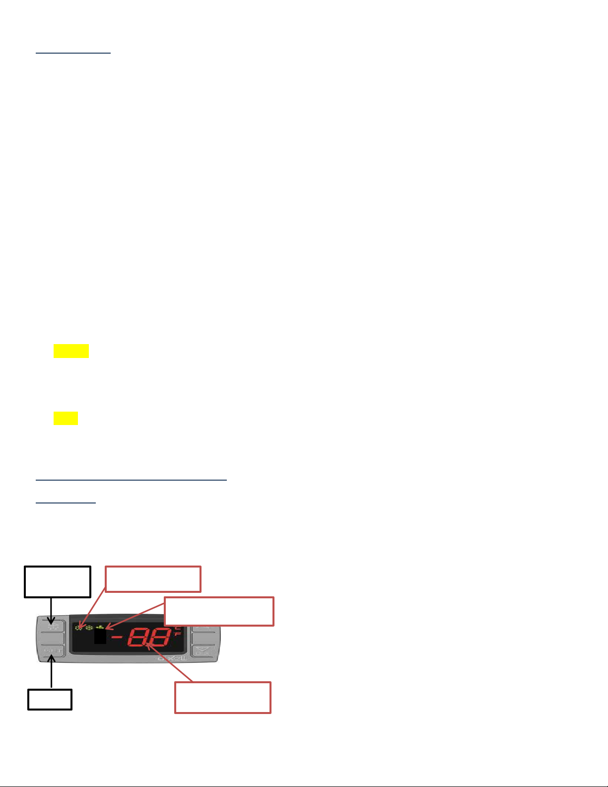
Snowflake “ON” – compressor enabled in
run cycle; control displays current cabinet
temperature.
Snowflake “Flashing” – anti short cycle
delay enabled to protect the compressor
from trying to start too frequently.
Melting Snowflake “ON” – defrost in
progress, control displays the letters “DE”
To view the control’s programmed “Set
Point” (cut-out temperature): press and
release the “Set Key.”
To initiate a manual defrost cycle: press and
hold the “Manual Defrost Key” for more
than 2 seconds.
Note: Manual defrost will not initiate if the cabinet
temperature is above 40 degrees F.
The electronic control combines the functions of
both a mechanical thermostat and a defrost timer
into a single control. The control also offers the
consumer the capability of monitoring the
operational status of the Vending Machine via the
icon and digital temperature display (located on the
face of the control). The controls have been
programmed by the manufacturer to operate the
Vending Machine within the design parameters of
the refrigeration system. The set-point (cut-out) for
these controls has been factory programmed for 16
degrees F, with a differential of 8 degrees F. Should
the user desire to alter the Set-Point, the new setpoints should not exceed +/- 4 degrees of the
original factory setting. It is not recommended to
alter any of the parameter programming in the
controls without first consulting the manufacturer.
The control is located on top of the merchandise
and contains two thermal-couple probes. Both probe
wires are routed through the cabinet’s suction line
hole and into the unit cooler assembly, which is
mounted to the interior ceiling of the cabinet.
The air sensing probe (“P1”) routes through the unit
cooler and has its’ sensing bulb secured to the outer,
left-hand wall of the unit cooler. Probe “P1”
monitors the air temperature in the Ice Breaker at
that location. During the normal operation of the
control, the digital display will show the cabinet
temperature at the probe “P1” location.
[7]
Page 8
Probe “P2” is inserted into the finned section of the
Note: Maintenance and repair of the electrical and
refrigeration systems should only be performed by
trained and qualified personnel.
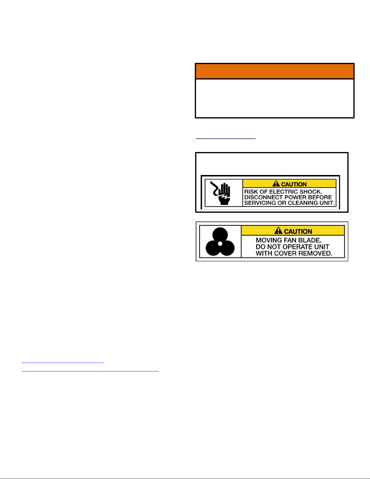
The defrost termination switch functions as a
possible fire protection device. Do not remove or
by-pass the termination switch from the defrost
circuit.
WARNING!
evaporator coil, near the top of the unit cooler
assembly. This probe monitors the temperature of
the evaporator coil during the defrost cycle. The
control is factory programmed to engage the defrost
cycle in 4 hour intervals. The defrost cycle is set to
run for 16 minutes, unless the temperature at “P2”
reaches 50 degrees F prior to the end of the cycle.
Should that occur, the temperature at “P2” will
override and end the defrost cycle. During the
defrost cycle, the control will display the letters
“DE” along with the melting snowflake icon.
returned to run mode, the termination switch will
re-set when the temperature at its’ surface reaches
35 degrees F.
Possible Displayed Alarm Codes:
“P1” – Air probe failure: The control will override the
“P1” functions and cycle the compressor at 5 minute
intervals, until the probe fault can be corrected.
“P2” – Evaporator probe failure: The control will
override the “P2” function and operate with a timed
defrost cycle, until the probe fault can be corrected.
“HA” – Maximum temperature alarm: The cabinet air
temperature has exceeded programmed maximums for a
period exceeding 15 minutes. The alarm will continue to
display until the cabinet temperature drops below
maximum levels.
“LA” – Minimum temperature alarm: The cabinet air
temperature has dropped below the programmed
minimum. This alarm will continue to display until the
cabinet temperature rises above the minimum level.
Note: Should a “P1” or “P2” alarm occur, check the
probe wire connections to the control prior to replacing
the probe wire.
For more detailed information regarding the
electronic control programming and instructions,
please contact: Leer Merchandiser Customer
Service Department. Phone: 800-766-5337. Contact
information is available on our web-site at
http://www.leerinc.com/icemerchandisers/merchandiser-sales-distributors/
The defrost circuit is equipped with a defrost
termination switch. This switch is attached to one of
the evaporator coil tubes (located inside the unit
cooler assembly). This switch senses temperature
and will cycle power off to the defrost heat element
should the temperature at the surface of the switch
reach 70 degrees F. This switch only terminates
power to the heat element and will not end the
timed defrost cycle. Once the Vending Machine has
Maintenance
General:
The recommended preventive maintenance intervals
will often vary depending upon the environment in
which the Vending Machine operates. A preventive
maintenance plan should be developed to aid in
determining realistic cleaning intervals.
Cleaning Condenser Coils:
It is recommended to inspect and clean the
condenser coil and fan blades every 3 month.
There are a variety of methods available for
cleaning the condenser coils. Keep in mind that the
debris is being drawn into the coil by the condenser
fan and the debris should be removed in the
opposite direction.
The simplest and preferred method would
involve the use of a vacuum cleaner to suck the
debris out of the coil from the outside surface.
Another method is using compressed air to blow
dust from the coil. The debris should be blown
out from the inside surface of the coil.
[8]
Page 9

WARNING: When using the compressed air, there
may be a cloud of dust released into the air
surrounding the machine.
It is recommended that the service person wear the
proper protective equipment (i.e. safety glasses and
a dust mask) when performing coil cleanings.
Note: DO NOT use any type of filter media in front
of the condenser coil to trap dust. Filter testing has
proven to create enough restriction of air flow to
reduce the efficiency of the coil’s heat exchange.
Defrosting:
The Vending Machine is designed to be selfdefrosting. They are equipped with an electronic
control that is factory set to run a maximum of 16
minute defrost cycle every 4 hours.
The heat generated by the defrost heater element
will melt the ice build-up on the evaporator coil and
the resulting water will drain through a tube out of
the back wall of the machine.
It is recommended to check the operation and
condition of the evaporator coil and for signs of
excessive ice buildup every 3 months.
Cleaning the Vending Machine:
The exterior of the Vending Machine including the
doors, can typically be cleaned with the use of
detergents dilluted in warm water followed with a
tap water rinse.
The exterior paint is capable of withstanding the use
of polishing compounds and most solvents. If using
stronger cleaning agents, they should be tested on a
small, inconspicuous areas prior to application onto
visible surfaces of the Vending Machine.
When cleaning the interior of the Vending Machine,
the use of detergents with strong odors (i.e. citrus
based cleaners), abrasive cleaners containing
chlorine bleach, and any form of solvent based
cleaners are not reccommended. They may leave
objectionable odors inside the cabinet which may be
absorbed by the ice being stored in the Vending
Machine.
Vending Machine Door Maintenance:
Routine inspection of the door gasket seal and the
action of the door’s hinges are recommended.
Door gaskets may mildew and stiffen over time.
The gasket is made of a soft, flexible PVC and can
be cleaned using most kitchen and bath cleaners
designed for mildew removal. Review manufacturer
information and instructions on any cleaning agent
prior to use to determine the cleaner’s compatability
with the surface being cleaned.
Vending Calibration:
Routine calibration is recommended every time the
unit is empty or near empty. This should be done
appromixatly once a month to insure proper
inventory. Follow steps from page 6. - Calibrate
Scale Before Loading Ice
Replacement Parts:
For replacement parts contact Leer Merchandiser
Customer Service Department at 800-766-5337.
Please have the Vending Machine model number
and serial number available to help identify the
parts for that specific machine.
Note: Leer electrical and refrigeration parts are
installed in compliance to UL Standard 471.
Replacement parts that are not UL Certified or are
not identical to the OEM installed part will void the
Vending Machine’s UL Listing and/or the Factory
warranty per "General Provisions” of the
accompanying warranty statement.
Part Returns:
To return parts, contact Leer Merchandiser
Customer Service Department to obtain a Return
Material Authorization (RMA) number. Return
authorized parts to this address:
Leer, Inc.
RMA# _______
206 Leer St.
New Lisbon, WI 53950
[9]
Page 10
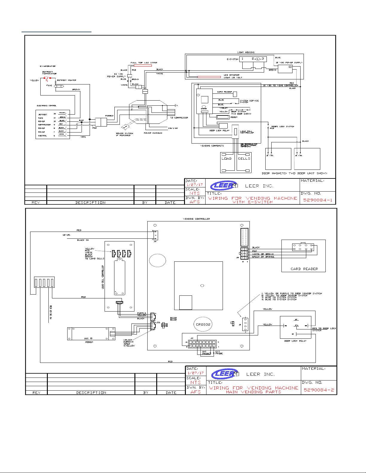
Wiring Diagram
[10]
Page 11
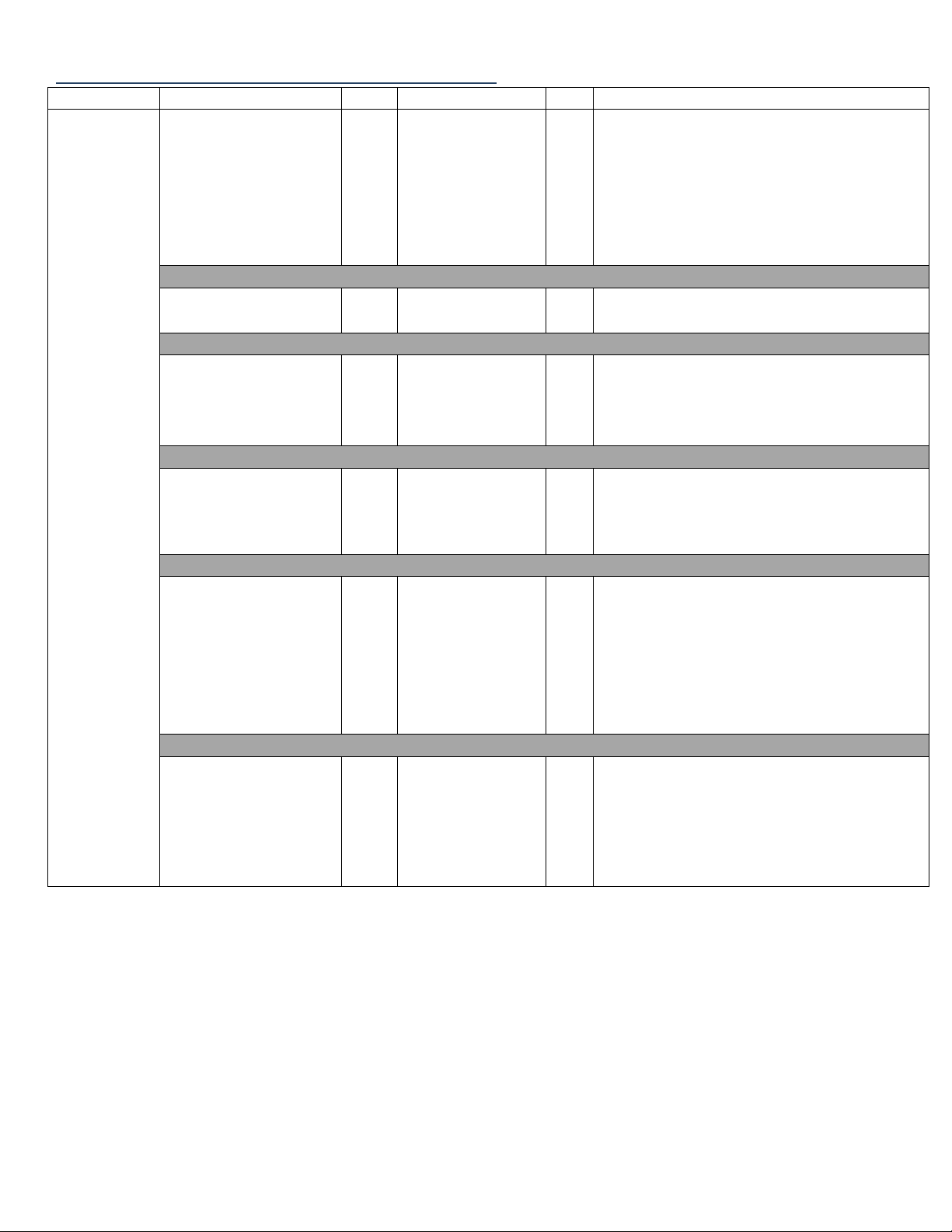
Refrigeration Trouble Shooting Table
Problem
Area to Check
Area to Check
Potential Faults
Ice Melting
Condensing unit fan
motor running?
Yes
Evaporator fan
motor(s) running
with snowflake
icon illuminated?
Yes
No
Broken fan blade
Possible dirty condenser
Defective evaporator fan motor
Defective wiring to evaporator fan
motor(s)
Compressor
functioning?
No
Defective relay, overload, capacitor,
compressor, or component wiring
Compressor
functioning: ice
build-up on
compressor coil?
Yes
Evaporator hose obstructed or kinked
Defective wiring in defrost circuit
Possible defective defrost heat, circuit,
or controller
Compressor
functioning: no ice
build-up on
compressor coil?
Yes
Incorrect refrigerant
Wrong or low voltage
Impurities in refrigerant charge
Interior light
functioning?
Yes
No
Defrost icon (left
hand of control
display)
No
Defective controller wiring
Defective evaporator fan wiring
Defective bulb
Defective controller wiring
Defective evaporator fan wiring
Condensing unit fan
and compressor
running when
plugged into
substitute power
source
No
Defective motor
Defective wiring
Defective controller
Defective wiring in circuit
[11]
Page 12
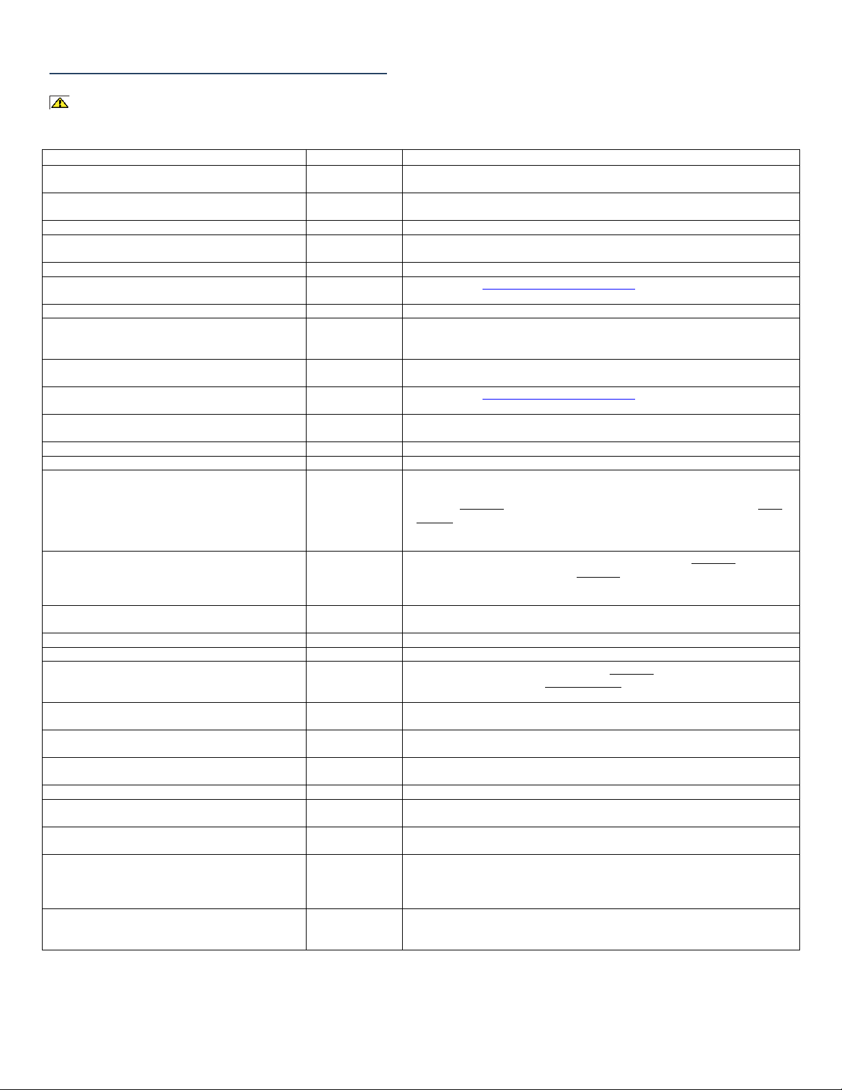
Vending Trouble Shooting Table
Trouble
Possible Cause
Corrective Measure
Card reader is not illuminated
Setup mode on
power up
Turn switch to run mode and power cycle machine.
Card Reader
Loose Connection
Check connection behind card reader and in vend box.
No Power
Check that the unit is plugged in and operating.
Doors not locking
Emergency switch
Check emergency entrapment switch located inside the merchandiser near or on the
light housing and switch to lock.
Failed magnets
Check magnets using a screwdriver to see if the magnets are energized.
Magnet
adjustment
Visit http://www.leerinc.com/support/ videos for instructions.
Failed relay
Check relay and connections in vend box.
Unit is not at
operating
temperature
Unit must be below 30 degrees before checking door locks. Press cancel on the card
reader to check internal and external temperature.
Door locks but has little holding force
Door or magnet
not lined up
Look at the magnets from the side of the box. All three bars on the magnet surface
must align with the door lock block.
Poor door seal / ice around doors
Magnet
adjustment
Visit http://www.leerinc.com/support/ videos for instructions.
No cell signal
Cellular signal
Press cancel to check signal strength. Recommend above -100dbm. Move antenna or
unit to a different location. -90dbm is better than -100dbm
Check antenna connections.
Unit is offline
No ice
Fill with ice.
Has ice but shows
0 bags
Adjust Tare value to show how many bags are in the unit. Press Enter and note Tare
and Net Weight before making any changes. In setup mode press the cancel button
until the Hardware icon is shown, press enter, press cancel repeatedly until Enter
Tare Wt is displayed on the screen and press enter, use cancel to change the value
and enter to move to the next digit. A higher Tare weight equals less bags and a
lower Tare weight equals more bags.
Missed sales
Door sensor
magnets
Check door sensor magnets. In set up mode, hit cancel to the Hardware icon, press
enter, press cancel repeatedly until Test Door is displayed, press enter. With doors
closed the display should say closed. Then open each door to check sensor operation.
Press cancel when finished to lock doors. Return key to run mode.
Bag weight is not
consistent
System will work best when bags are +-.5 pounds of bag weight.
Door error code (DM01)
Door open
Close door.
Bad sensor
Follow missed sales corrective measure to verify.
Card reader will not read credit card
Bad card reader
Check in setup mode, press cancel until the Hardware icon is displayed, press enter,
press cancel repeatedly until Test Card Reader is displayed, press enter and swipe a
credit card. If the card information is displayed the reader is working.
Load cell device error
Damaged load
cell
Check for obvious damage to the load cell feet or cables.
Unit is not on the
ground
Skid plates must be on the ground and the unit must be removed from the shipping
skid.
Load cell
controller
Check load cell controller for power or unplugged connections in vend box.
Crown/Hourglass not illuminated
Photo sensor
Will only work in a dark environment.
Unit shows more or less ice than known inventory
Unit Calibration
Calibrate unit before putting it into service, after the unit is level and all feet are
touching the ground.
Adjust the Tare weight to closely match the bags in machine. See Corrective Measure
under Unit is off line/ Has ice but unit shows 0 bags.
Tare WT 0 after power cycle or power failure
Battery
Check battery on Vend Controller for connection. Check battery voltage. Should be
close to 3 volts, replace if needed. If battery is removed you must check all settings
such as SGAI, Bag Weight and Bag Variance. Recalibrate machine and retest. Power
cycle and confirm settings saved.
Display shows Celsius for internal and external
temperature
Website
Celsius or Fahrenheit is determined by weight measurement on the website. If unit is
set to KG it will show Celsius on the display.
Caution: Multiple Voltages- Check serial tag for main unit power. Vending parts are 12VDC. LED exterior lighting is 24VDC.
Disconnect main power before preforming service.
[12]
Page 13

Warranty
Vending Machines: Seller warrants the Vending Machine under normal use and service, for
one (1) year for the component parts (to be shipped by seller), and ninety (90) days for repair
labor from the date of original shipment. The Vending Machine compressor motor is warranted
for five (5) years from the date of original shipment. SELLER MUST BE CONTACTED AND
PROVIDED A VENDING MACHINE SERIAL NUMBER FOR WARRANTY CLAIM. This
applies only to goods installed in the United States. Seller’s obligation under this warranty shall
be limited to repair (subject to the limitations below) or replacement of any part(s), F.O.B.
Seller’s factory, which prove(s) defective within the applicable warranty period. Seller reserves
the right to inspect defective part(s) and may at Seller’s discretion require return of part(s) to
Seller’s factory for inspection. The determination as to whether any defect exists shall be made
in Seller’s sole judgment.
GENERAL PROVISIONS APPLICABLE TO ALL WARRANTIES AND PRODUCTS:
Seller shall not be liable for any breach of any express warranty set forth above unless Seller is
informed immediately upon the discovery of defective part(s). The warranties described above
are not assignable and shall operate only in favor of the original buyer/user. In event of any
claim for breach of express warranty, Seller shall be responsible for labor charges for repair or
replacement of any defective part(s) or assembly only for defects reported to Seller within
ninety (90) days after the date of installation. ALL LABOR CHARGES SHALL BE
AUTHORIZED OR APPROVED BY SELLER PRIOR TO THE REPAIR OR
REPLACEMENT OF PART(S). In all other events, Seller shall not be responsible for any labor
charges. Labor charges shall only include standard straight time labor hours at the site of
product installation, and shall exclude charges for travel time, mileage, or other premium
charges. These warranties shall not apply to any goods, or any part thereof, which may have
been subject to any damage in transit, accident, negligence, abuse or misuse, unauthorized
alteration or repair, acts of nature or failure to follow any of the Seller’s manuals or instructions,
if in Seller’s sole judgment, such act, omission or event has detrimentally affected the physical
condition, use or operating qualities of the product. SELLER MAKES NO WARRANTY,
EXPRESS OR IMPLIED, BY REASON OF LAW, STATUE OR OTHERWISE, INCLUDING
ANY IMPLIED WARRANTY OF MERCHANTABILITY OR FITNESS FOR A
PARTICULAR USE OR PURPOSE, AND ALL IMPLIED WARRANTIES ARE HEREBY
DISCLAIMED. SELLER SHALL NOT BE LIABLE FOR LOSS OF GOODS,
MERCHANDISE OR OTHER PROPERTY, OR LOSS OF PROFITS, RESULTING FROM
PRODUCT DEFECTS. IN NO EVENT SHALL SELLER’S LIABILITY UNDER ANY
CIRCUMSTANCES FOR ANY BREACH OF CONTRACT OR FOR ANY OTHER CLAIM
BY BUYER AGAINST SELLER EXCEED THE CONTRACT PRICE OF THE GOODS
SOLD HEREUNDER WITH RESPECT TO WHICH SUCH CLAIM ARISES.
MODEL NO. ______________________ SERIAL NO. _____________________
[13]
Page 14
Please read section I. Packaging of the manual
before uncrating the Vending Machine.
Use caution when moving your
Vending Machine
Weight sensors are located under the Vending
Machine. Only use pallet jack or fork truck with
care, away from weight sensors.
[14]
 Loading...