

Page 1

Leer, Inc.
206 Leer Street, P.O. Box 206
New Lisbon, WI 53950
1-800-766-5337
www.leerinc.com
ICE MERCHANDISER
INSTALLATION, OPERATION, AND SERVICE
MANUAL
WARNING: This product can expose you to chemicals
including nickel, which is known to the State of California to
cause cancer (For more information go to
www.p65warnings.ca.gov)
1070005 1/20
Page 2

Table of Contents
Start-UP ............................................................................................................................................................................ 3
Storage and Transportation: ......................................................................................................................................... 3
Packaging: .................................................................................................................................................................... 3
Installation ........................................................................................................................................................................ 3
Placing Merchandiser: .................................................................................................................................................. 3
Merchandiser Leveling: ................................................................................................................................................ 3
Electrical: ..................................................................................................................................................................... 3
Condensate Evaporator: ............................................................................................................................................... 4
Operation .......................................................................................................................................................................... 4
Temperature Controls: .................................................................................................................................................. 4
Mechanical Controls Thermostat: ................................................................................................................................ 5
Mechanical Controls: Defrost Timer: ........................................................................................................................... 5
Electronic Controls: Digital Display: ........................................................................................................................... 5
Operating Mode Display: ............................................................................................................................................. 5
Electronic Control Operation: ...................................................................................................................................... 5
Cold Wall Control: ....................................................................................................................................................... 6
Auto-Defrost Control: .................................................................................................................................................. 6
Electronic Control Startup: ........................................................................................................................................... 6
Possible Displayed Alarm Codes: ................................................................................................................................ 6
Loading Ice: .................................................................................................................................................................. 6
Maintenance ...................................................................................................................................................................... 7
Cleaning the Merchandiser: .......................................................................................................................................... 7
Cleaning Door Gaskets: ................................................................................................................................................ 7
Cleaning Condenser Coils: ........................................................................................................................................... 7
Defrosting the Merchandiser: ....................................................................................................................................... 8
Cold Wall Defrost Methods: ........................................................................................................................................ 8
Auto-Defrost Methods: ................................................................................................................................................. 8
Auto-Defrost Mechanical Timer .................................................................................................................................. 9
Auto-Defrost Electronic Control: ................................................................................................................................. 9
Glass Door Models and Maintenance: ....................................................................................................................... 10
Solid Door Models and Maintenance ......................................................................................................................... 10
Decaling Recommendations Solid Door: ................................................................................................................... 10
Door Gaskets and Hardware ....................................................................................................................................... 10
Electronic Control- CW and AD Wiring Diagram ......................................................................................................... 13
Mechanical Control- CW and AD Wiring Diagram ....................................................................................................... 13
Replacement Parts List ................................................................................................................................................... 14
Warranty ........................................................................................................................................................................... 3
2
Page 3
Start-UP
Storage and Transportation:
The merchandiser should be stored and
transported in an upright position. It is not
recommended to tilt the merchandiser. If the
merchandiser is tilted beyond 45° of vertical, oil
may drain from the compressor causing premature
failure.
Do Not stack merchandisers on top of one another
due to risk of falling. Falling merchandisers could
result in damaged units or serious injuries. It is
recommended to use warehouse racking design to
accommodate the weight of the merchandisers
and prevent falling.
Packaging:
Prior to installation, the outer packaging on the
merchandiser will need to be removed. The
majority of the packaging materials can be
recycled and disposed of in an environmentally
friendly manner. The wooden skid is secured to
the underside of merchandiser with hex-headed
screws and will require the use of a 3/8" hexsocket for screw removal. Glass door models are
shipped with door support brackets installed
between the merchandiser's door opening(s) and
the bottom rail of the door. These support brackets
need to be removed prior to operation of the
merchandiser. Failure to remove the brackets will
affect the seal of the door gasket to the cabinet
face.
Merchandiser Leveling: The merchandiser
installation location should have a solid, level
base. If the merchandiser is exhibiting a slight
forward lean, the front of the cabinet should be
blocked to bring the cabinet to a level position.
On auto-defrost models, a forward lean may affect
proper draining of the unit cooler assembly during
the defrost cycle.
Leveling Kit (4 pc.) No. 5350029, which
is compatible for use on most cabinet
models, is available.
Contact the Merchandiser Sales Department at
Leer, Inc. for additional information.
Electrical:
Warning! Component parts shall only be
replaced with like components. Electrical and
servicing should be done by licensed
professionals. Disconnect power before
performing service. Certain models contain
multiple voltages. Leer does not assume
responsibility for any damage to people or
things deriving from violation, improper use or
in any case not in compliance with Leer’s
instructions.
Installation
Placing Merchandiser: When placing the
merchandiser, allow a minimum of 3 inches of air
space from all surfaces of the cabinet and any
surrounding structures. This air space allows for
air flow over the surface of the cabinet, thus
reducing condensation and aid in the drying of
these surfaces. On outdoor auto-defrost models,
the 3-inch space behind the merchandiser will also
help ensure that the evaporator drain tube, which
exits the back wall, is not being restricted during
the defrost cycle.
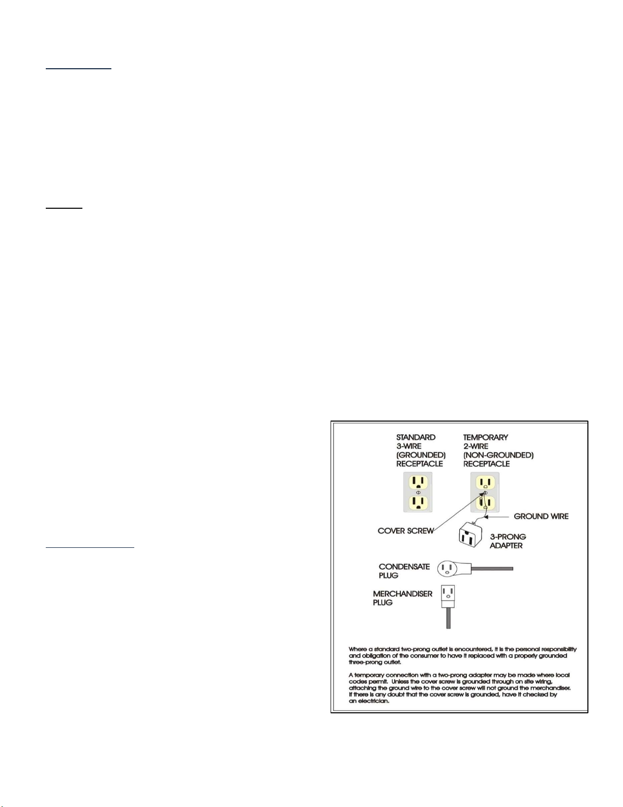
Figure 1: Grounding
3
Page 4
The Merchandiser must be plugged into a
dedicated and properly grounded 115V/60hz/1Ph
circuit with a circuit fuse or breaker rated at a 15
or 20 Amps depending on model. The electrical
service connections to the merchandiser must be
compliant with national electric code and local
codes that may apply. DO NOT use extension
cords. The 20 Amp plug configuration, that some
models come with, should NOT be removed.
Some models are equipped with a main power
switch. If so equipped, make sure the switch is in
the OFF position before plugging the
merchandiser into the lower receptacle of the
electrical outlet.
WARNING: Operating more than one appliance
on the same circuit may result in voltage
fluctuations when both appliances are operating
simultaneously. This voltage fluctuation may
cause the circuit breaker to trip and/or may cause
voltage drops. As a result, the power to the
merchandiser may be interrupted and freezing
performance can be adversely affected which may
cause equipment damage and /or product loss.
Voltage supply to the merchandiser must not vary
more than ±10 percent of the normal 115V.
Information regarding the electrical voltage and
frequency being supplied to the merchandiser can
be found on the merchandiser’s serial data plate
typically located at the upper left corner of the
merchandiser’s interior. Information regarding the
maximum fuse/circuit breaker size required for
the specific model is available from the
condensing unit data plate.
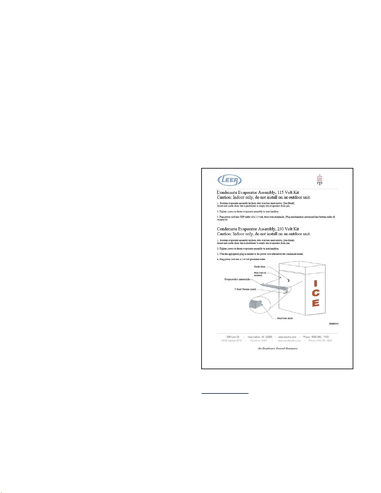
Condensate Evaporator: Indoor auto-defrost
models are supplied with a condensate evaporator
heater assembly which is packaged with
instructions and shipped inside the merchandiser.
It will require simple installation by the consumer
(see Figure 2). A separate copy of this instruction
sheet is supplied with the condensate evaporator
assembly. The condensate evaporator assembly
contains a drip pan to collect water generated by
the merchandiser’s defrost cycle and a heat
element to evaporate the water. Once energized,
the heat element in the condensate evaporator
assembly is continuously generating heat. The
merchandiser is to be placed so that there is at
least 1 inch of air space between the back surface
of the condensate evaporator housing and any
wall surface behind the cabinet which allows for
heat dissipation away from the surface of the wall.
The main power cord should also be routed to
avoid pinching.
Note: Do not operate an indoor auto-defrost
merchandiser without having a condensate
evaporator assembly installed under the
evaporator drain tube exiting the back wall of the
cabinet. Failure to install this assembly will result
in water draining directly onto the floor during the
defrost cycle. This may result in water damage to
the floor and create a hazardous slip condition in
the area surrounding the merchandiser.
Figure 2: Condensate Evaporator Installation
Operation
Temperature Controls: Merchandisers are
currently available with either mechanical
controls (optional) or an electronic control
(standard).
4
Page 5
Defrost
Set
Mechanical Controls Thermostat:
The compressor is controlled by the classic
thermostat where the engagement and
disengagement of the thermostat is controlled by
the expansion and contraction of gas within a
sensing tube. Merchandisers with mechanical
thermostats are factory set to operate at a cut-out
temperature of 18° F +/-2°. The thermostat has an
adjustment knob that allows a limited adjustment
range. Rotating the adjustment knob clockwise
will lower the cabinet temperature while a
counterclockwise rotation will raise the cabinet
temperature. Rotating the adjustment knob fully
counter-clockwise will shut off power completely
to the merchandiser’s condensing unit. The
thermostat has a pre-set differential of 7° F, which
is not adjustable.
On cold wall (CW) cabinet models, the thermostat
is located on top of the cabinet under the
condensing unit cover housing. The sensor tube
inserts through the ceiling of the cabinet and exits
near the interior back wall.
On automatic defrost (AD) cabinet models, the
thermostat is housed inside the unit cooler
assembly that is mounted to the interior ceiling of
the cabinet.
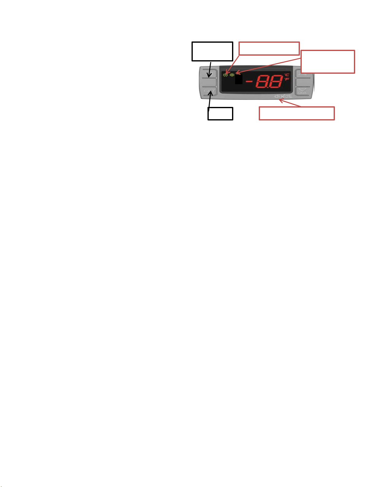
Electronic Controls: Digital Display:
Manual
Defrost Enabled
Compressor
Enabled Icon
Temperature & Settings
Operating Mode Display:
Snowflake “ON” – compressor enabled in
run cycle; control displays current cabinet
temperature.
Snowflake “Flashing” – anti short cycle
delay enabled to protect the compressor
from trying to start too frequently.
Melting Snowflake “ON” – defrost in
progress, control displays the letters “DE”
To view the control’s programmed “Set
Point” (cut-out temperature): press and
release the “Set Key.”
To initiate a manual defrost cycle: press
and hold the “Manual Defrost Key” for
more than 2 seconds.
Note: Manual Defrost will not initiate unless the
unit is at standard operating temperatures.
Mechanical Controls: Defrost Timer:
The defrost timer is located under the condensing
unit housing. The timer will engage the
merchandisers defrost cycle once every 4 hours
for a duration of 16 minutes. The standard timer,
supplied with most merchandisers, is pre-set and
non-adjustable. The timer may be manually
advanced into defrost by rotating the advancement
knob in a clockwise direction. The knob is located
on the rear of the timer casing. Manual
advancement into the defrost mode will re-set the
next controlled defrost cycle to take place in 4
hours.
The automatic defrost function is available on
cabinet models designated as “auto-defrost” (AD).
The cold wall (CW) cabinet models do not have
an electronically controlled defrost and require
manual de-icing of the cabinet’s interior walls.
Electronic Control Operation:
The electronic control combines the functions of
both the mechanical thermostat and defrost timer
into a single control. The control also offers the
consumer the capability of monitoring the
operational status of the merchandiser via the icon
and digital temperature display (located on the
face of the control). The controller has been
programmed by Leer to operate the merchandiser
within the design parameters of the refrigeration
system. The set-point (cut-out) for these controls
has programmed parameters for 16°F, with a
differential of 8°F. Should the user desire to alter
the Set-Point, the new set-points should not
exceed +/- 4° of the original factory setting. Do
not alter any of the programming parameters in
the controls without first consulting with Leer.
There are two separate electronic controls
available based upon the cabinet type; Cold Wall
or Auto-Defrost.
5
Page 6

Cold Wall Control: The CW control is located
under the condensing unit housing. The control
has a single thermal-couple probe wire used to
monitor the air temperature inside the cabinet.
The probe enters through the top of the cabinet
and is secured at a specific location where the
back wall and ceiling of the interior meet. The
control will display the air temperature in the
cabinet at the probe’s location. Although the
control has a Manual Defrost Key, this action is
non-functional on the CW cabinet models (see the
defrost instructions for CW cabinet models in the
“MAINTENANCE” section of this manual).
Auto-Defrost Control: The AD control is also
located under the condensing unit cover and
contains two thermal-couple probe wires. Both
probe wires are routed through the cabinet’s
suction line hole and into the unit cooler
assembly, which is mounted to the interior ceiling
of the cabinet. The Red Air Sensing Probe (“P1”)
routes through the unit cooler and has its’ sensing
bulb secured to the outer, left-hand wall of the
unit cooler. Probe “P1” monitors the air
temperature in the merchandiser at that location.
During the normal operation of the control, the
digital display will show the cabinet temperature
at the probe “P1” location. The Black Probe “P2”
is inserted into the finned section of the
evaporator coil, near the top of the unit cooler
assembly. This probe monitors the temperature of
the evaporator coil during the defrost cycle.
Electronic Control Startup: Turn the switch
if equipped into the ON position. After a 2minute delay, the compressor and the
condenser fan should start. The evaporator fan
motors and the light fixture will operate
immediately when power is applied. The
condensing unit will continue to run until the air
temperature in the cabinet reaches +16°F.
Note: If a defrost is required upon startup the
controller will enter defrost mode after the 2minute delay. Normal operation will resume upon
defrost termination and a short drip time.
Possible Displayed Alarm Codes:
“P1” – Air Probe failure: The control will
override the “P1” functions and cycle the
compressor at 5-minute intervals, until the probe
fault can be corrected.
“P2” – Evaporator Probe failure: The control will
override the “P2” function and operate with a
timed defrost cycle, until the probe fault can be
corrected.
“HA” – Maximum Temperature Alarm: The
cabinet air temperature has exceeded programmed
temperature for a period exceeding 15 minutes.
The alarm will continue to display until the
cabinet temperature drops below maximum levels.
“LA” – Minimum Temperature Alarm: The
cabinet air temperature has dropped below the
programmed minimum. This alarm will continue
to display until the cabinet temperature rises
above the minimum level.
Note: Should a “P1” or “P2” alarm occur, check
the probe wire connections to the control prior to
replacing the probe wire.
For more information regarding the electronic
control program and instructions, please contact:
Leer, Inc. Merchandiser Division Customer
Service. Phone: 800-766-5337 or our web-site at
https://www.leerinc.com
Loading Ice: The merchandiser should be pre-
chilled prior to loading with ice. Pre-chilling will
aid the merchandiser in reaching storage
temperature at a faster rate once loaded and
reduce the risk of melting product. Do not over
fill the merchandiser with ice!
Cold Wall Models: If the bagged ice blocks off air
flow from the front of the cabinet to the control’s
air probe, the control may not respond quickly
enough to maintain proper cabinet temperature.
Allow a minimum of 6 inches clearance between
the top of the ice stack and the ceiling of the
cabinet interior. This distance will allow a
6
Page 7
pathway for warmer air entering the cabinet
during door openings to migrate to the sensing
bulb on the probe.
Auto-Defrost Models: Avoid stacking ice above
the top edge of the air ducts that are installed on
the walls of the cabinet interior. Blocking off
these air ducts may restrict the even distribution
of cold air throughout the cabinet, this may result
in warm spots developing within the cabinet.
Also, do not stack ice high enough to block off the
evaporator fans in the unit cooler assembly. The
evaporator fans are intended to pull warm air
entering the cabinet into the unit cooler and then
push that warm air across the surface of the
evaporator coil. This process removes the heat
prior to distributing the air into the cabinet.
Maintenance
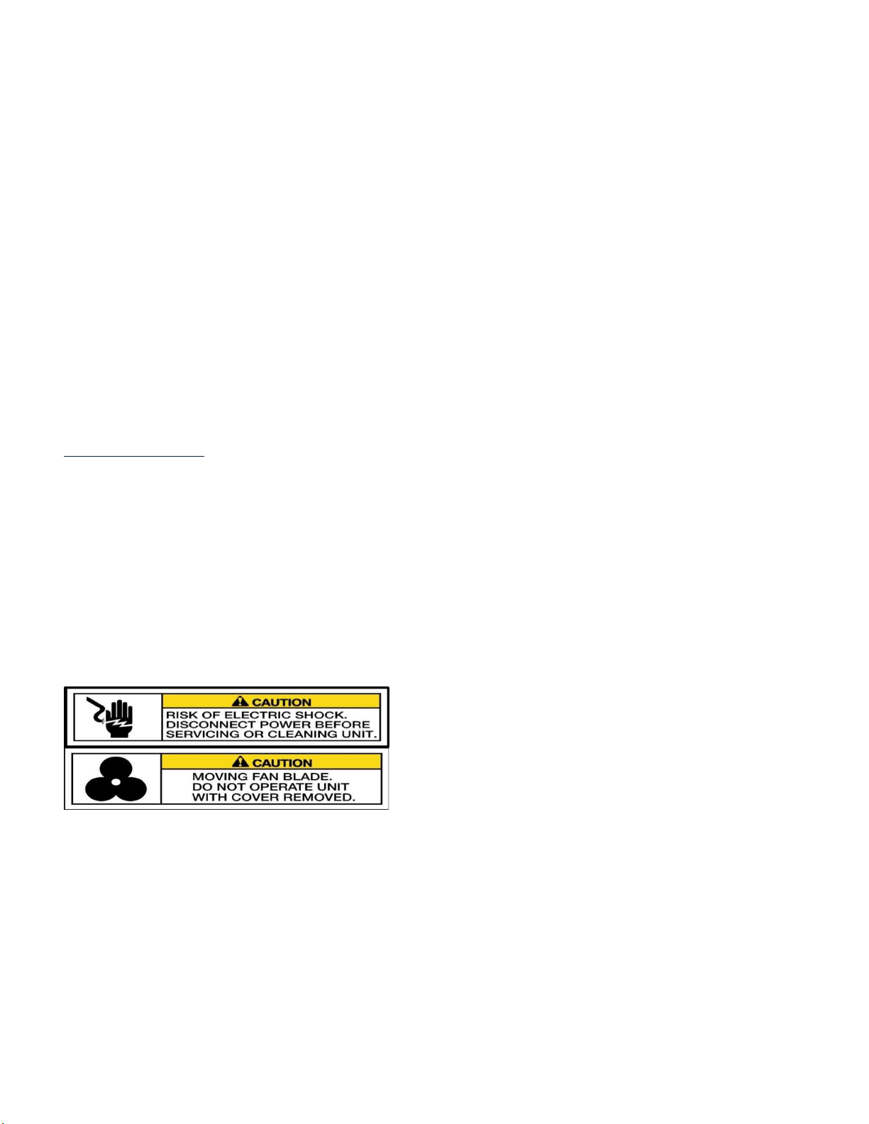
Note: Component parts shall only be replaced
with like components. Maintenance and repair of
the electrical and refrigeration systems should
only be done by trained and qualified personnel.
Disconnect power before performing service.
Certain models may contain multiple voltages.
Leer does not assume responsibility for any
damage to people or things deriving from
violation, improper use, or in any case not in
compliance with Leer’s instructions.
Cleaning the Merchandiser: The
merchandiser should be cleaned annually. In
corrosive environments such as coastal regions
and areas where deicing chemicals and road salts
are used, more frequent cleaning is recommended.
The exterior of the merchandiser can typically be
cleaned with the use of detergents dilluted in
warm water followed with a tap water rinse. The
exterior paint is capable of withstanding the use of
polishing compounds and most solvents. If using
stronger cleaning agents, they should be tested on
a small, inconspicuous areas prior to application
onto visible surfaces of the merchandiser. If
cleaning the interior of the merchandiser, the use
of detergents with strong odors (i.e. citrus based
cleaners, abrasive cleaners containing chlorine
bleach, and any form of solvent based cleaners)
are not reccommended. They may leave
objectionable odors inside the cabinet which may
be absorbed by the ice being stored in the
merchandiser.
Cleaning Door Gaskets: Door gaskets may
mildew and stiffen over time. The gasket is made
of a soft, flexible rubber-like material that can be
cleaned using most kitchen and bath cleaners
designed for mildew removal. Review
manufacturer information and instructions on any
cleaning agent prior to use to determine the
cleaner’s compatability with the surface being
cleaned.
Cleaning Condenser Coils:
It is recommended to inspect and clean the
condenser coil and fan blades every 3 months.
There are a variety of methods available for
cleaning the condenser coils. Keep in mind that
the debris is being drawn into the coil by the
condenser fan and the debris should be removed
in the opposite direction.
The simplest and preferred method would
involve the use of a vacuum cleaner to suck
the debris out of the coil from the outside
surface.
Another method is using compressed air to
blow dust from the coil. The debris should be
blown out from the inside surface of the coil.
WARNING: When using compressed air, there
may be a cloud of dust released into the air
surrounding the machine.
It is recommended that the service person wear
proper protective equipment (i.e. safety glasses
and a dust mask) when performing coil cleanings.
Note: DO NOT use any type of filter media in
front of the condenser coil to trap dust. Filter
testing has proven to create enough restriction of
air flow to reduce the efficiency of the coil’s heat
exchange.
7
Page 8

Defrosting the Merchandiser:
The Auto Defrost merchandiser is designed to be
self-defrosting. The heat generated by the defrost
heater element will melt the ice build-up on the
evaporator coil and the resulting water will drain
through a tube out of the back wall of the
machine.
It is recommended to check the operation and
condition of the evaporator coil and for signs of
excessive ice buildup every 3 months
The means and methods of the ice removal are
dependent upon whether the merchandiser is a
Cold Wall model or an Auto-Defrost model.
Cold Wall Defrost Methods: The evaporator
tubing for the cold wall cabinet models are
located within the walls of the cabinet. After the
cold wall merchandiser is energized, a visual
inspection of the cabinet’s interior will reveal a
serpentine frost pattern developing on the ceiling
and walls. This frost pattern represents the
configuration of the evaporator tubing as it’s
attached to the inside surface of the cabinet. As
humidity enters the cabinet, it will collect and
accumulate along this frost-line pattern. As the
frost-line expands and builds in thickness, it will
slow the heat transfer between the cabinet walls
and the evaporator tubing. The cold wall cabinet
models do not have the design capability to selfdefrost. In order to defrost the cold wall models,
product will need to be emptied from the cabinet
and the power to the cabinet disconnected.
Defrosting requires the entire interior surface of
the cabinet to be warmed above freezing in order
to melt and remove the build-up of ice from the
interior surfaces.
Power to the merchandiser can be turned off by
merely unplugging the cabinet from its power
source. If the merchandiser is equipped with a
mechanical thermostat, power can also be turned
off by rotating the temperature adjustment knob to
its full counterclockwise position. After the
defrost operation is complete, return the knob to
its normal position to re-energize the condensing
unit. If the cold wall cabinet has an electronic
control, power can also be turned off by use of the
ON/OFF toggle switch located on the control box
of certain cabinet models. If the toggle switch is
not present on the control box, the only means of
disconnecting power is to unplug the main power
cord at the power source. Although the electronic
control on the CW merchandiser has a defrost key
on its display face, this feature does not function
with the CW cabinet design and will not switch
off power if pressed.
With the merchandiser de-energized, the defrost
process can be expedited with the addition of hot
air being forced through the cabinet’s door
opening(s). As the ice build-up softens, a plastic
ice scraper may be utilized to aid in the removal
of ice from interior of the cabinet. If possible,
avoid the use of metal ice scrapers, ice picks, or
hammers as these tools may inadvertently
penetrate through the wall of the cabinet, puncture
the evaporator tube, and cause irreparable
damage.
A floor drain is present in most merchandiser
models. For outdoor models, the floor drain plug
can be removed to allow water drainage. If
draining to the ground is not desirable or if the
merchandiser is located indoors, the water may be
removed with the use of a wet-vac and disposed
of. It is suggested that some of the time allocated
to defrost the cold wall cabinet may be utilized for
the cleaning of the condenser coil as well as
inspecting the condition of wiring insulation, door
gaskets, and spring-loaded hinges.
Auto-Defrost Methods: Auto-Defrost models
are equipped to be self-defrosting and enter
defrost mode once every four hours automatically.
During the defrost cycle, the power to the
refrigeration system will be automatically redirected to the defrost circuit. This will shut down
power to the condensing unit, evaporator fan
motors and also send power to a heat element that
is attached to the surface of the evaporator coil.
The heat generated by the element will melt the
ice build-up on the evaporator coil and the
resulting melt water will drain through a tube out
of the back wall of the merchandiser.
On outdoor cabinet models, the melt water will
exit the drain tube directly to the ground.
On indoor cabinet models, the consumer needs to
install the condensate evaporator heater assembly
8
Page 9

(described in the Installation section of this
manual) onto the exterior back wall of the cabinet.
The melt water from the defrost cycle will drain
into a catch pan where it will then be heated to the
point of evaporation. The function of the
condensate evaporator’s heat element should be
checked routinely. Failure of the element could
result in an over-flow condition for the assembly’s
drain pan. A simple check of the heater would be
a touch test of the surface temperature of the
assembly’s housing. The condensate evaporator’s
heat element is energized continuously so the
surface of the housing should always be hot to the
touch. If testing the heat element with a meter, the
element can be unplugged from its’ power source
and a resistance reading can be taken through the
plug’s bladed terminals. The condensate heater is
rated to generate 125 watts of power, which
translates to approximately 106 ohms of
resistance.
Auto-Defrost Mechanical Timer: The AD
merchandiser may come equipped with a
mechanical timer (as described in the Operation
section of this manual). The timer is factory set
for a 16 minute defrost cycle to occur at 4-hour
intervals. During its’ run-cycle, the timer supplies
power to the thermostat, condensing unit, and
evaporator fan motors. During the defrost cycle,
the timer switches power from the run-circuit to
the defrost-circuit and energizes the defrost
heater. The AD mechanical timer may be
manually advanced to a defrost mode by rotating
the advancement knob (located on the back of the
timer) in a clockwise direction until the defrost
switch engages. The advancement knob rotates in
a clockwise direction only.
The mechanical defrost circuit is equipped with a
defrost termination switch and is attached to one
of the evaporator coil tubes (located inside the
Unit Cooler Assembly). This switch senses
temperature and will cut power to the defrost heat
element should the temperature at the surface of
the switch reach 70° F. This switch terminates
power to the heat element and will not end the
timed defrost cycle. Once the unit has returned to
run mode, the termination switch will re-set when
the temperature at its’ surface reaches 30° F.
Auto-Defrost Electronic Control: For
Merchandisers with an electronic control (as
described in the OPERATION section of this
manual). The timer is factory set for a 24 minute
defrost cycle to occur at 4-hour intervals. Like the
mechanical timer, the electronic control will
switch power from run mode (condensing unit and
evaporator fans) to defrost mode (defrost heat
element). Whereas the mechanical timer operates
strictly on a timed cycle, the duration of the
electronic control’s defrost cycle is controlled by
the temperature at the sensor probe “P2.” If the
temperature at this probe reaches 60°F prior to the
24-minute timed cycle ending, the control will
override the timed cycle and immediately switch
power from the defrost mode to a drip time then
standard run mode. If temperature is not reached
at probe “P2,” the defrost cycle will continue for
the entire 24- minute programmed cycle prior to
returning to run mode. Energizing the defrost
circuit in the electronic control can be verified
with the illumination of the “melting snowflake”
and the letters “DE” appearing on the control’s
display.
The electronic defrost circuit is equipped with a
defrost termination safety switch and is attached
to one of the evaporator coil tubes (located inside
the Unit Cooler Assembly). This switch senses
temperature and will cut power to the defrost heat
element should the temperature at the surface of
the switch reach 100° F. This switch only
terminates power to the heat element and will not
end the timed / temperature defrost cycle. Once
the merchandiser has returned to run mode, the
termination safety switch will re-set when the
temperature at its’ surface reaches 70° F.
Warning! The defrost termination / safety
switch functions as a possible fire protection
device. Do not remove or by-pass the switch from
the defrost circuit.
Note: If an electronic control AD unit loses
power, it will automatically enter a defrost cycle.
9
Page 10

Glass Door Models and Maintenance:
The glass door is designed for use on indoor units
or in a controlled environment. It is constructed
with a non-heated, triple-pane glass-pack, with
both inner and outer panes being tempered. To
avoid possible condensation on the outer surface
of the door, case temperature in the merchandiser
should be maintained near its’ designed set-point
of 16°F +/- 4° and ambient dew-points around the
cabinet location should be kept below 60°F. Any
household glass cleaner can be used to clean the
surface of the door. The glass door’s gasket is a
rubber bellows-style magnetic gasket. The
replacement gasket has an insert dart that installs
into a retaining slot in the door frame. The gasket
can be started in-place with light hand pressure,
followed with mild impact pressure applied with a
dead-blow hammer to ensure that the legs of the
dart penetrate fully into the slot. During
replacement, always set the gasket at the 4corners of the door first to reduce stretching the
gasket. If the door gasket appears to be in good
condition but is failing to seal to the surface of the
cabinet, both the spring-load tension and
adjustment of the hinges should be checked.
A simple test of the spring-load tension is to open
the door just enough to insert two fingers between
the surface of the cabinet and the handle side of
the door. When the fingers are withdrawn, there
should be enough tension set on the hinge springloads to slowly move the door to a closed
position. If the door does not move from this twofinger location, it’s likely that either the springload requires re-tensioning or lubrication. If the
door moves part way from the two-finger location
but stops short of the cabinet, the compression of
the gasket along the hinge side of the door should
be checked. If there is too much compression, the
door will bind when closed and should have its
hinge-mount location checked and possibly
adjusted. Removing the hinge covers will expose
the spring-loads for tension adjustment or
removal. Removal of the spring-load will expose
the hinge-adjustment plate and mounting screws
should hinge adjustment be required. See Figure
3 for instruction regarding spring-load installation
and adjustment.
Solid Door Models and Maintenance:
Cabinets designed for outdoor use will have a
metal clad door that has been insulated with the
same urethane foam insulation as the cabinet.
The exterior metal is stucco embossed to hide
minor impacts and is coated with a fluorocarbon
paint system. This paint system was designed to
withstand years of outdoor exposure. For routine
cleaning of the door’s exterior surface, a mild
detergent diluted in warm water should be
adequate.
Decaling Recommendations Solid Door:
a) Use a decal with a 2-mil cast vinyl
substrate. Cast vinyl contains less
memory than a calendared vinyl or a
polyester substrate and will conform to the
embossed surface with the least amount of
stress on the decal’s adhesive.
b) The decal’s adhesive should have a
minimum peel-strength rating of 80 oz.
/inch.
c) Clean the surface of the door with
isopropyl alcohol and either air dry or dry
with a clean cloth.
d) Heating the surface of the door
immediately before applying the decal will
aid the adhesive bond of the decal. Never
apply a decal to a surface that is colder
than 50° F.
e) Use a soft roller or plastic squeegee to
apply the decal and press it into the
embossed surface of the metal. Applying a
small amount of heat to the surface of the
decal will aid in this process.
Door Gaskets and Hardware: Routine
inspection of the door gasket seal and the action
of the door’s hinges are recommended. If damage
has occurred to the gasket, it may allow outside
air to penetrate the cabinet and the gasket should
be replaced. The upright solid door (measuring
27” x 46”) utilizes the same hinge as the glass
door. The slant door (measuring 27” x 27”)
utilizes a hinge which is not spring-loaded. Both
doors have the same gasket profile, which has a
barbed dart that inserts into a slot opening in the
surface of the door frame. See Figure 4 for
instructions on solid door gasket replacement.
10
Page 11
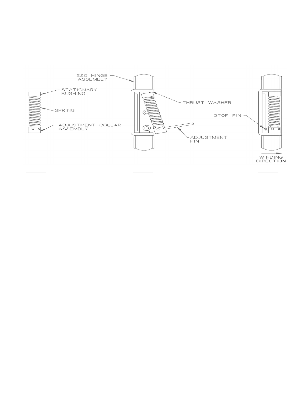
SPRING CARTRIDGE INSTALLATION INSTRUCTIONS
Figure 1 Figure 2 Figure 3
1) Install No. 220 Hinge with Adjustment Plate.
2) Assemble Spring Cartridge. Grease bushing end of pin prior to insertion into Stationary Bushing. Apply
a small amount of grease to the hinge-pin hole on the end of the Adjustment Collar Assembly. (Fig. 1).
3) Place Thrust Washer and Stationary Bushing over square pin in the Hinge and insert the Adjustment Pin
into the Adjustment Collar. Using the Adjustment Pin, compress the Spring and place the Adjustment Collar
over the round pin (Fig. 2).
4) Using the Adjustment Pin, turn the Adjustment Collar until the Pin contacts the Hinge. Then insert the
Stop Pin in hole of Adjustment Collar (Fig. 3).
Collar. Failure to do so may cause the Stop Pin to become dislodged. Inserting the Adjustment Pin more
than halfway thru the Adjustment Collar can cause partial push out of the Stop Pin. Repeat adjustment until
desired tension is reached. The maximum tension is 6 holes or approximately 1-1/4 turns.
5) Install Cover on Hinge.
WARNING:
Figure 3: Spring Install Instructions
Use safety glasses when installing and adjusting spring tension.
CAUTION:
The Stop Pin must fully seat on Adjustment
11
Page 12
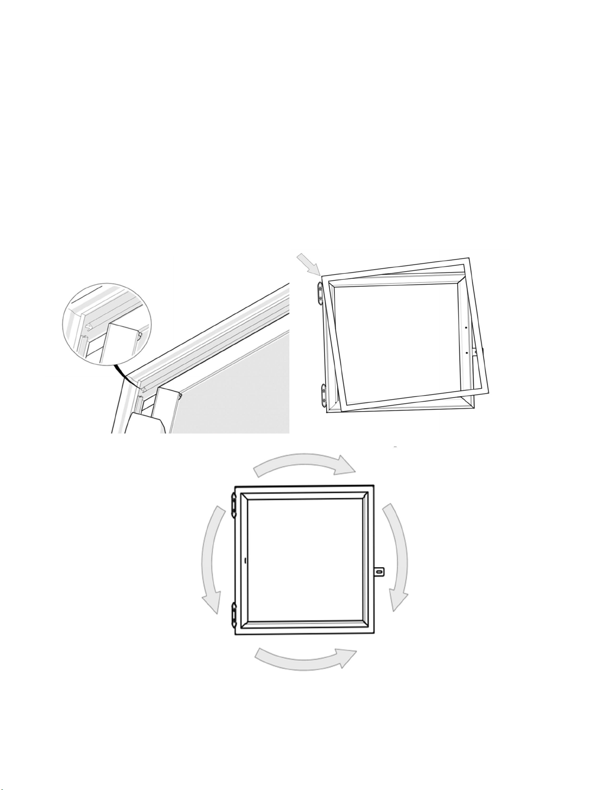
Solid Door Magnetic Gasket Replacement Instructions:
1. Position solid door on a flat non-abrasive surface, exterior side down.
2. Remove old gasket by grasping firmly at the corner and pulling away from the door frame extrusion.
3. Inspect the extruded slot to insure there are no particles to interfere with the new gasket installation.
4. Align new gasket with door corners and use thumb to press into frame.
5. Start at one corner of the frame and begin pressing the new gasket into the slot. Using a non abrasive
tool such as a hammer head works well for this application. Apply downward pressure while moving
along the permeter of the frame. Excessive pressure may strech the gasket and cause bulging at the
corners.
Gasket Detail View Step 4
Step 5
Figure 4: Door Gasket Install
12
Page 13
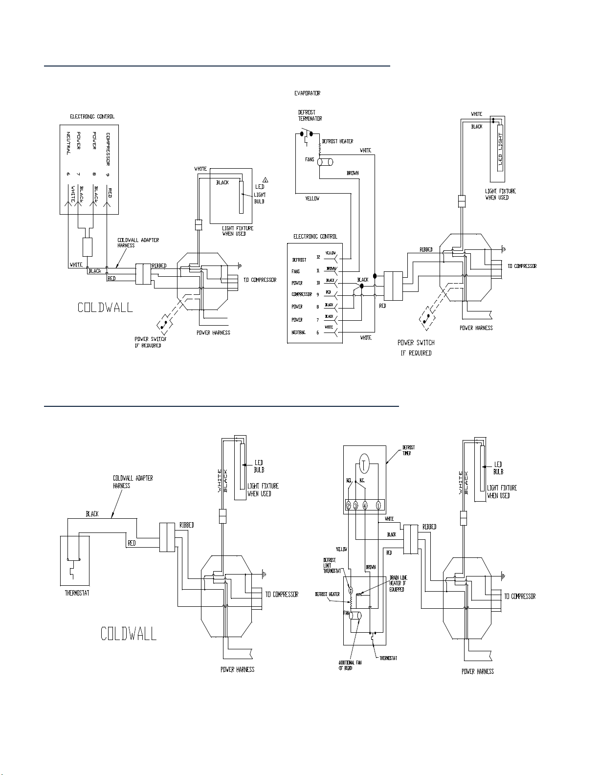
Electronic Control- CW and AD Wiring Diagram
Mechanical Control- CW and AD Wiring Diagram
13
Page 14

12. Door,
Stucco Charcoal Gray
5591027
Silver w/spring & cover
Silver Hinge Cover
1990008
Spring
-
Load Kit (Kason 220 hinge)
1990002
"ICE" Decals (Blue) One Set
1070070
21. Rain Shield for 27" x 46" solid door
5120098
-5
22. Ice Pallet 22" x 28" Black
1050079
23. LED lamp (2’ T8 cool white clear)
1216009
automatic defrost models (White)
25. Cond. evaporator heat element 125W
1261004
26. Merchandiser leveling kit 4 pc
Replacement Parts List
ITEM DESCRIPTION PART # ITEM DESCRIPTION PART #
1. Condensing Unit: Provide
condensing unit model number
2. Thermostat - Mechanical 1328046
Timer - Mechanical 1328023
Electronic Control – CW XRO2 1328034
Electronic Control – AD XRO4 1328035
Sensor Probe Evap (Black) 1328055
Sensor Probe Room (Red) 1328056
Power Harness w/o Switch Terminal 1270062
Power Harness with Switch Terminal 1270070
Toggle Switch (for PN 1270070) 1213042
3. Unit Cooler Evaporator Parts:
Fan Guard 1396023
Fan Blade 1392008
Fan Mounting Bracket 5120140
Fan Motor 1393029
Mechanical Defrost Termination
Switch 30/70F 1328003
Electronic Defrost Safety
Switch 70/100F 1328004
LCL 120 Defrost Heater – 400W 1261007
LCL 170 Defrost Heater – 600W 1261008
LCL 190/280 Defrost Heater – 800W 1261009
4. Full Top Enclosure: Provide the
merchandiser model number.
5. "ICE" Decal for full top (Red) 1070076
“ICE” Decal for full top (Blue) 1070069
6. Cover w/o decal 5848004-5
Cover w/ decal 5848000-5
7. "Packaged Ice" Decal. 1070068
8. J-Bolt for all solid doors 1160008
9. Door Hasp for all solid doors 5120001
10. Door Handle for all solid doors 1914001
11. Check Chain 1915001
Note: Providing the cabinet model and serial number will aid in identifying parts for a specific merchandiser.
Return authorized parts to this address: Leer, Inc.
206 Leer St.
New Lisbon, WI 53950
- Contact Leer Merchandiser Customer Service Dept. to obtain a Return Material Authorization (RMA) Number.
NOTE: Leer electrical and refrigeration parts are installed in compliance to UL Standard 471. Replacement parts that are not UL Certified or
are not identical to the OEM installed part, will void the merchandiser’s UL Listing and/or the Factory warranty per "General Provisions” of
the accompanying warranty statement.
27" x 27"with gasket
13. Door Gasket for 1030016
27" x 27" solid door
14. Hinge with cover for 27" x 27" solid
door
15. Door, Stucco Charcoal Gray 5591035
27" x 46" with gasket
16. Door Gasket for 1030014
27" x 46" solid door
17. Glass Door, 28" x 47" Silver Frame
18. Door Gasket for 28" x 47" glass door
19. Door Hinge for 28" x 47" door:
20. "ICE" Decals (Red) One Set
24. Condensate evaporator assy. for
1911019
1412012
1490007
1911002
1070074
5349040
5350029
14
Page 15
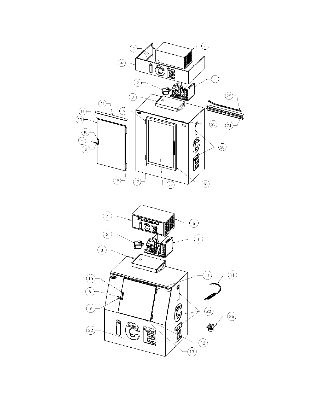
Upright Models
Slant Models
Note: LP models are similar in design to slant models except for refrigeration location.
2
Page 16

Warranty
ICE MERCHANDISERS: Seller warrants the merchandiser under normal use and service, for one (1) year for
the component parts (to be shipped by seller), and ninety (90) days for repair labor from the date of original
shipment. The merchandiser compressor motor is warranted for five (5) years from the date of original
shipment. SELLER MUST BE CONTACTED AND PROVIDED A MERCHANDISER SERIAL NUMBER
FOR WARRANTY CLAIM. This applies only to goods installed in the United States, Canada or Mexico.
Seller’s obligation under this warranty shall be limited to repair (subject to the limitations below) or
replacement of any part(s), F.O.B. Seller’s factory, which prove(s) defective within the applicable warranty
period. Seller reserves the right to inspect defective part(s) and may at Seller’s discretion require return of
part(s) to Seller’s factory for inspection. The determination as to whether any defect exists shall be made in
Seller’s sole judgement.
GENERAL PROVISIONS APPLICABLE TO ALL WARRANTIES AND PRODUCTS: Seller shall not
be liable for any breach of any express warranty set forth above unless Seller is informed immediately upon the
discovery of defective part(s). The warranties described above are not assignable and shall operate only in favor
of the original buyer/user. In event of any claim for breach of express warranty, Seller shall be responsible for
labor charges for repair or replacement of any defective part(s) or assembly only for defects reported to Seller
within ninety (90) days after the date of installation. ALL LABOR CHARGES SHALL BE AUTHORIZED OR
APPROVED BY SELLER PRIOR TO THE REPAIR OR REPLACEMENT OF PART(S). In all other events,
Seller shall not be responsible for any labor charges. Labor charges shall only include standard straight time
labor hours at the site of product installation, and shall exclude charges for travel time, mileage, or other
premium charges. These warranties shall not apply to any goods, or any part thereof, which may have been
subject to any damage in transit, accident, negligence, abuse or misuse, unauthorized alteration or repair, acts of
nature or failure to follow any of the Seller’s manuals or instructions, if in Seller’s sole judgement, such act,
omission or event has detrimentally affected the physical condition, use or operating qualities of the product.
SELLER MAKES NO WARRANTY, EXPRESS OR IMPLIED, BY REASON OF LAW, STATUE OR
OTHERWISE, INCLUDING ANY IMPLIED WARRANTY OF MERCHANTABILITY OR FITNESS FOR A
PARTICULAR USE OR PURPOSE, AND ALL IMPLIED WARRANTIES ARE HEREBY DISCLAIMED.
SELLER SHALL NOT BE LIABLE FOR LOSS OF GOODS, MERCHANDISE OR OTHER PROPERTY,
OR LOSS OF PROFITS, RESULTING FROM PRODUCT DEFECTS. IN NO EVENT SHALL SELLER’S
LIABILITY UNDER ANY CIRCUMSTANCES FOR ANY BREACH OF CONTRACT OR FOR ANY
OTHER CLAIM BY BUYER AGAINST SELLER EXCEED THE CONTRACT PRICE OF THE GOODS
SOLD HEREUNDER WITH RESPECT TO WHICH SUCH CLAIM ARISES.
MODEL NO. ______________________
SERIAL NO. ______________________
3
 Loading...