

Operations, Service, and Parts Manual
LEEBOY MODEL 8515D CONVEYOR PAVER
Manual No. 1015239-01
This manual applies to
Serial Number 133074
and above.

Thumb Index
SAFETY
INFORMATION AND SPECIFICATIONS
COMPONENT LOCATION
OPERATION
MAINTENANCE
1
2
3
4
5
SCHEMATICS
ILLUSTRATED PARTS LIST
6
7

Disclaimer
All information, illustrations and specications in this manual are based on the latest information available
at the time of publishing. The illustrations used in this manual are intended as representative reference
views only. Moreover, because of our continuous product improvement policy, we may modify information,
illustrations and/or specications to explain and/or exemplify a product, service or maintenance
improvement. We reserve the right to make any change at any time without notice. VT LeeBoy, Inc., VT
LeeBoy, LeeBoy, and Rosco are all the same entity and are used interchangeably.
Title 40, Code of Federal Regulations (CFR) 1068
This product meets certied-emission requirements set by the EPA (Environmental Protection Agency),
governed by Title 40 CFR 1068, which species actions that are prohibited by law and lists civil penalties
for noncompliance. As part of those regulations, modication or rendering inoperative any emissionrelated component can subject you to government penalties (and void your warranty). Tampering with
emission controls is in violation of federal law, and can result in civil penalties of up to $3,750 each day an
engine or piece of equipment is operated in violation.
Please be aware that you are responsible for maintaining the machine and the certied emission engine
installation. Failure to comply to comply could result in penalties as listed above and void the warranty on
this engine and this machine.
For more information, visit: https://www.epa.gov/laws-regulations/regulations
California Proposition 65 Warning
Diesel engine exhaust and some of its constituents are known to the State of California to cause cancer,
birth defects, and other reproductive harm.
Battery posts, terminals and other related accessories contain lead and lead compounds, chemicals
known to the State of California to cause cancer and other reproductive harm. Wash hands after handling.
©2016 VT LeeBoy, Inc.
LeeBoy reserves all copyright and other rights in this manual and the manual’s content. No part of this
manual may be reproduced or used in any way without the written permission of VT LeeBoy, Inc., except as
necessary to operate LeeBoy equipment.
iv
LeeBoy 8515D Conveyor Paver

TABLE OF CONTENTS
Page
Safety Precautions . . . . . . . . . . . . . . . . . . . . . . . . . . . . . 1-4
Machine Precautions . . . . . . . . . . . . . . . . . . . . . . . . . . . . 1-7
Hot Material Precautions . . . . . . . . . . . . . . . . . . . . . . . 1-7
Hydraulic Systems Precautions . . . . . . . . . . . . . . . . . . . 1-7
Refueling Precautions . . . . . . . . . . . . . . . . . . . . . . . . 1-8
Battery Precautions . . . . . . . . . . . . . . . . . . . . . . . . . 1-8
Starting and Stopping Precautions . . . . . . . . . . . . . . . . . . 1-8
Parking Precautions . . . . . . . . . . . . . . . . . . . . . . . . . 1-8
Operating Precautions . . . . . . . . . . . . . . . . . . . . . . . . 1-8
Poor Visibility . . . . . . . . . . . . . . . . . . . . . . . . . . . . 1-9
Storage Precautions . . . . . . . . . . . . . . . . . . . . . . . . . 1-9
Maintenance Precautions . . . . . . . . . . . . . . . . . . . . . . 1-9
Safety Decals . . . . . . . . . . . . . . . . . . . . . . . . . . . . . . . 1-10
Safety Decals Care . . . . . . . . . . . . . . . . . . . . . . . . . 1-11
Decal Installation (Sticker Type) . . . . . . . . . . . . . . . . . . . 1-11
Decal Installation (Top Protected) . . . . . . . . . . . . . . . . . . 1-11
Limited Warranty Policy . . . . . . . . . . . . . . . . . . . . . . . . . . 2-2
Contact Information . . . . . . . . . . . . . . . . . . . . . . . . . . . . 2-3
Specication Charts . . . . . . . . . . . . . . . . . . . . . . . . . . . . 2-4
Torque Specications . . . . . . . . . . . . . . . . . . . . . . . . . . . 2-7
Standard Inch Fasteners . . . . . . . . . . . . . . . . . . . . . . . 2-7
Metric Fasteners . . . . . . . . . . . . . . . . . . . . . . . . . . . 2-8
Hydraulic Fittings . . . . . . . . . . . . . . . . . . . . . . . . . . 2-8
Determining Proper Torque . . . . . . . . . . . . . . . . . . . . . 2-9
Component Location . . . . . . . . . . . . . . . . . . . . . . . . . . . . . 3-1
LeeBoy 8515D Conveyor Paver v

Components Overview . . . . . . . . . . . . . . . . . . . . . . . . . . . 3-3
Hydraulic System . . . . . . . . . . . . . . . . . . . . . . . . . . 3-3
Hopper and Conveyors . . . . . . . . . . . . . . . . . . . . . . . 3-3
Augers . . . . . . . . . . . . . . . . . . . . . . . . . . . . . . . . 3-4
Operator Platform . . . . . . . . . . . . . . . . . . . . . . . . . . 3-4
Screed . . . . . . . . . . . . . . . . . . . . . . . . . . . . . . . 3-4
Electrical System . . . . . . . . . . . . . . . . . . . . . . . . . . 3-4
Standard Equipment/Options . . . . . . . . . . . . . . . . . . . . 3-4
Machine Overview . . . . . . . . . . . . . . . . . . . . . . . . . . . . . 3-5
Left Control Panel . . . . . . . . . . . . . . . . . . . . . . . . . . . . . 3-6
Right Control Panel. . . . . . . . . . . . . . . . . . . . . . . . . . . . . 3-8
Center Control Panel . . . . . . . . . . . . . . . . . . . . . . . . . . . . 3-10
Steering and Speed Control Box . . . . . . . . . . . . . . . . . . . . . . 3-11
Screed Controls . . . . . . . . . . . . . . . . . . . . . . . . . . . . . . 3-12
Burner Controls . . . . . . . . . . . . . . . . . . . . . . . . . . . . . . 3-13
Propane Tank Controls . . . . . . . . . . . . . . . . . . . . . . . 3-13
Steering Wheel (Option) . . . . . . . . . . . . . . . . . . . . . . . . . . 3-14
Electric Heat (Option) . . . . . . . . . . . . . . . . . . . . . . . . . . . 3-14
Operation . . . . . . . . . . . . . . . . . . . . . . . . . . . . . . . . . . 4-1
General Information . . . . . . . . . . . . . . . . . . . . . . . . . . . . 4-3
Receiving the Machine . . . . . . . . . . . . . . . . . . . . . . . . . . . 4-3
Initial and Daily Inspection . . . . . . . . . . . . . . . . . . . . . . 4-3
Start-Up Procedure . . . . . . . . . . . . . . . . . . . . . . . . . . . . 4-4
Stopping the Engine . . . . . . . . . . . . . . . . . . . . . . . . . . . . 4-4
DPF Regeneration (REGEN) . . . . . . . . . . . . . . . . . . . . . . . . 4-4
PV480 Powerview Display . . . . . . . . . . . . . . . . . . . . . . . . . 4-5
Gauge Screen . . . . . . . . . . . . . . . . . . . . . . . . . . . . 4-5
Set Points and Throttle Speed . . . . . . . . . . . . . . . . . . . . 4-5
Soft Keys (Buttons) . . . . . . . . . . . . . . . . . . . . . . . . . 4-6
Status Icons . . . . . . . . . . . . . . . . . . . . . . . . . . . . . 4-7
Main Menu . . . . . . . . . . . . . . . . . . . . . . . . . . . . . . 4-8
Gauges . . . . . . . . . . . . . . . . . . . . . . . . . . . . . . . 4-8
Diagnostics . . . . . . . . . . . . . . . . . . . . . . . . . . . . . 4-9
System Info . . . . . . . . . . . . . . . . . . . . . . . . . . . . . 4-10
User Settings . . . . . . . . . . . . . . . . . . . . . . . . . . . . 4-12
Regeneration Messages . . . . . . . . . . . . . . . . . . . . . . . 4-14
vi
LeeBoy 8515D Conveyor Paver

Messages, Cautions, Warnings . . . . . . . . . . . . . . . . . . . 4-17
Driving the Paver . . . . . . . . . . . . . . . . . . . . . . . . . . . . . . 4-18
Operator Control Station . . . . . . . . . . . . . . . . . . . . . . . 4-18
Steering and Speed Control . . . . . . . . . . . . . . . . . . . . . 4-18
Paver Operation . . . . . . . . . . . . . . . . . . . . . . . . . . . . . . 4-19
Spray Down . . . . . . . . . . . . . . . . . . . . . . . . . . . . . 4-19
Heating the Screed . . . . . . . . . . . . . . . . . . . . . . . . . 4-20
Hopper Wings . . . . . . . . . . . . . . . . . . . . . . . . . . . . 4-22
Conveyors . . . . . . . . . . . . . . . . . . . . . . . . . . . . . . 4-23
Hydraulic Cut-Off Gates . . . . . . . . . . . . . . . . . . . . . . . 4-23
Electric Flight Screw . . . . . . . . . . . . . . . . . . . . . . . . . 4-24
Set the Screed Extension, Flight Screw and Endgate . . . . . . . . . 4-24
Sonic Auger Sensor . . . . . . . . . . . . . . . . . . . . . . . . . 4-26
Starting to Pave . . . . . . . . . . . . . . . . . . . . . . . . . . . . . . 4-27
Basic Paving . . . . . . . . . . . . . . . . . . . . . . . . . . . . . 4-27
Setting the Crown . . . . . . . . . . . . . . . . . . . . . . . . . . 4-28
Mat Texture Adjustment . . . . . . . . . . . . . . . . . . . . . . . 4-29
815HD Screed Extension Double Adjustment (Option) . . . . . . . . 4-30
Unloading and Loading . . . . . . . . . . . . . . . . . . . . . . . . . . . 4-30
Unloading . . . . . . . . . . . . . . . . . . . . . . . . . . . . . . 4-30
Loading . . . . . . . . . . . . . . . . . . . . . . . . . . . . . . . 4-31
Tie-Down Procedure . . . . . . . . . . . . . . . . . . . . . . . . . 4-31
Optional Components . . . . . . . . . . . . . . . . . . . . . . . . . . . 4-32
Auger Extensions Option . . . . . . . . . . . . . . . . . . . . . . . 4-32
Umbrella Option . . . . . . . . . . . . . . . . . . . . . . . . . . . 4-32
Screed Sloping Extensions . . . . . . . . . . . . . . . . . . . . . 4-32
Steering Wheel Option . . . . . . . . . . . . . . . . . . . . . . . . 4-32
Roll-Up Curb Attachments . . . . . . . . . . . . . . . . . . . . . . 4-32
Truck Hitch Attachment Option . . . . . . . . . . . . . . . . . . . . 4-33
Electric Screed Options . . . . . . . . . . . . . . . . . . . . . . . 4-33
Topcon® Sonic and Dual Grade Control . . . . . . . . . . . . . . . 4-34
Rubber or Steel Track Options . . . . . . . . . . . . . . . . . . . . 4-34
815HD (Heavy Duty) Electric Screed . . . . . . . . . . . . . . . . . 4-34
LeeBoy 8515D Conveyor Paver
vii

Maintenance . . . . . . . . . . . . . . . . . . . . . . . . . . . . . . . . . 5-1
Maintenance Schedule . . . . . . . . . . . . . . . . . . . . . . . . . . . 5-3
Routine Maintenance . . . . . . . . . . . . . . . . . . . . . . . . . . . . 5-5
Preparing Paver for Maintenance . . . . . . . . . . . . . . . . . . 5-5
Every 10 Hours or Daily Routine Maintenance . . . . . . . . . . . . 5-5
Every 50 Hours or Weekly Routine Maintenance . . . . . . . . . . . 5-5
Every 100 Hour or Monthly Maintenance . . . . . . . . . . . . . . . 5-6
Every 250 Hours or Quarterly Routine Maintenance . . . . . . . . . 5-6
Every 500 Hours or Semi-Annual Routine Maintenance . . . . . . . 5-6
Every 1000 Hours or Annual Routine Maintenance . . . . . . . . . . 5-6
Torque Hub Lubrication . . . . . . . . . . . . . . . . . . . . . . . 5-6
Lubrication Points . . . . . . . . . . . . . . . . . . . . . . . . . . 5-7
Maintenance Adjustments . . . . . . . . . . . . . . . . . . . . . . . . . 5-8
Conveyor Flight Chain . . . . . . . . . . . . . . . . . . . . . . . . 5-8
Conveyor Drive Chain . . . . . . . . . . . . . . . . . . . . . . . . 5-8
Auger Drive Chain Adjustment . . . . . . . . . . . . . . . . . . . . 5-9
Screed Extension Top Guide Adjustment . . . . . . . . . . . . . . . 5-9
Track Tension Pressure Relief . . . . . . . . . . . . . . . . . . . . 5-10
Conveyor Switch Adjustment . . . . . . . . . . . . . . . . . . . . . 5-10
Torque Hub Hydraulic Motor Gear Adjustments . . . . . . . . . . . 5-11
Engine Maintenance . . . . . . . . . . . . . . . . . . . . . . . . . . . . 5-12
Check Engine Lubrication Oil . . . . . . . . . . . . . . . . . . . . 5-12
Change Engine Oil and Filter . . . . . . . . . . . . . . . . . . . . . 5-13
Change Air Filter . . . . . . . . . . . . . . . . . . . . . . . . . . . 5-13
Fuel System . . . . . . . . . . . . . . . . . . . . . . . . . . . . . . . . 5-14
Fuel Tank . . . . . . . . . . . . . . . . . . . . . . . . . . . . . . 5-14
Change Fuel Filter . . . . . . . . . . . . . . . . . . . . . . . . . . 5-14
Water Separator . . . . . . . . . . . . . . . . . . . . . . . . . . . 5-15
Hydraulic System . . . . . . . . . . . . . . . . . . . . . . . . . . . . . 5-16
Check Hydraulic Oil . . . . . . . . . . . . . . . . . . . . . . . . . 5-16
Change Hydraulic Oil and Filter . . . . . . . . . . . . . . . . . . . 5-16
Electrical System . . . . . . . . . . . . . . . . . . . . . . . . . . . . . . 5-17
Battery Servicing . . . . . . . . . . . . . . . . . . . . . . . . . . . 5-18
Alternator . . . . . . . . . . . . . . . . . . . . . . . . . . . . . . 5-18
Screed Electric Heat (Option) . . . . . . . . . . . . . . . . . . . . . . . 5-19
Screed Electric Heat Elements . . . . . . . . . . . . . . . . . . . . 5-19
viii
LeeBoy 8515D Conveyor Paver

Element Resistance Testing . . . . . . . . . . . . . . . . . . . . . 5-20
Heating Elements . . . . . . . . . . . . . . . . . . . . . . . . . . 5-20
Generator Voltage Testing . . . . . . . . . . . . . . . . . . . . . . 5-21
Generator Capacitor . . . . . . . . . . . . . . . . . . . . . . . . . 5-22
Replacement Procedures . . . . . . . . . . . . . . . . . . . . . . . . . 5-22
Front Idler . . . . . . . . . . . . . . . . . . . . . . . . . . . . . . 5-22
Track Tension Cylinder . . . . . . . . . . . . . . . . . . . . . . . 5-23
Track Rollers . . . . . . . . . . . . . . . . . . . . . . . . . . . . 5-23
Track Sprocket (Steel or Poly) . . . . . . . . . . . . . . . . . . . . 5-23
Rubber Track (Option) . . . . . . . . . . . . . . . . . . . . . . . . 5-24
Rear Conveyor Shaft, Bearings and Sprockets . . . . . . . . . . . . 5-24
Conveyor Drive Motors. . . . . . . . . . . . . . . . . . . . . . . . 5-25
Auger and Inner Bearings . . . . . . . . . . . . . . . . . . . . . . 5-25
Auger Motors . . . . . . . . . . . . . . . . . . . . . . . . . . . . 5-26
Main Screed Wear Plate . . . . . . . . . . . . . . . . . . . . . . . 5-27
Screed Extension Wear Plate . . . . . . . . . . . . . . . . . . . . 5-28
Torque Hub . . . . . . . . . . . . . . . . . . . . . . . . . . . . . 5-29
Two-Speed Hydraulic Motors . . . . . . . . . . . . . . . . . . . . 5-30
Conveyor Switch Replacement . . . . . . . . . . . . . . . . . . . . 5-31
Weldment . . . . . . . . . . . . . . . . . . . . . . . . . . . . . . . . . 5-31
Troubleshooting . . . . . . . . . . . . . . . . . . . . . . . . . . . . . . 5-32
Plus One . . . . . . . . . . . . . . . . . . . . . . . . . . . . . . . 5-32
Test Ports . . . . . . . . . . . . . . . . . . . . . . . . . . . . . .5-33
Troubleshooting Chart . . . . . . . . . . . . . . . . . . . . . . . . 5-34
PV480 Diagnostic Trouble Code (DTC) Chart. . . . . . . . . . . . . . . . 5-37
Electrical System (1 of 11) . . . . . . . . . . . . . . . . . . . . . . . . . . 6-3
Electrical System (2 of 11) . . . . . . . . . . . . . . . . . . . . . . . . . . 6-5
Electrical System (3 of 11) . . . . . . . . . . . . . . . . . . . . . . . . . . 6-7
Electrical System (4 of 11) . . . . . . . . . . . . . . . . . . . . . . . . . . 6-9
Electrical System (5 of 11) . . . . . . . . . . . . . . . . . . . . . . . . . . 6-11
Electrical System (6 of 11) . . . . . . . . . . . . . . . . . . . . . . . . . . 6-13
Electrical System (7 of 11) . . . . . . . . . . . . . . . . . . . . . . . . . . 6-15
Electrical System (8 of 11) . . . . . . . . . . . . . . . . . . . . . . . . . . 6-17
Electrical System (9 of 11) . . . . . . . . . . . . . . . . . . . . . . . . . . 6-19
Electrical System (10 of 11) . . . . . . . . . . . . . . . . . . . . . . . . . 6-21
Electrical System (11 of 11) . . . . . . . . . . . . . . . . . . . . . . . . . 6-23
LeeBoy 8515D Conveyor Paver
ix

Lower Control, Sloping (Left) . . . . . . . . . . . . . . . . . . . . . . . . 6-25
Lower Control, Sloping (Right) . . . . . . . . . . . . . . . . . . . . . . . 6-27
Lower Control, Non-Sloping (Left) . . . . . . . . . . . . . . . . . . . . . 6-29
Lower Control, Non-Sloping (Right) . . . . . . . . . . . . . . . . . . . . . 6-31
Auxilliary Harness . . . . . . . . . . . . . . . . . . . . . . . . . . . . . 6-33
Generator Control to Bulkhead Harness . . . . . . . . . . . . . . . . . . 6-35
Bulkhead to Generator Harness . . . . . . . . . . . . . . . . . . . . . . 6-37
Electric Steering Cord, 4 Feet . . . . . . . . . . . . . . . . . . . . . . . 6-39
Dash Assembly (1 of 5) . . . . . . . . . . . . . . . . . . . . . . . . . . . 6-41
Dash Assembly (2 of 5) . . . . . . . . . . . . . . . . . . . . . . . . . . .6-43
Dash Assembly (3 of 5) . . . . . . . . . . . . . . . . . . . . . . . . . . . 6-45
Dash Assembly (4 of 5) . . . . . . . . . . . . . . . . . . . . . . . . . . . 6-47
Dash Assembly (5 of 5) . . . . . . . . . . . . . . . . . . . . . . . . . . . 6-49
Gauge Panel (1 of 2) . . . . . . . . . . . . . . . . . . . . . . . . . . . . 6-51
Gauge Panel (2 of 2) . . . . . . . . . . . . . . . . . . . . . . . . . . . . 6-53
Plus One Harness (1 of 2) . . . . . . . . . . . . . . . . . . . . . . . . . . 6-55
Plus One Harness (2 of 2) . . . . . . . . . . . . . . . . . . . . . . . . . 6-57
Ultrasonic Power Harness . . . . . . . . . . . . . . . . . . . . . . . . . 6-59
Steering Wheel Box (Option) . . . . . . . . . . . . . . . . . . . . . . . . 6-61
Dual joystick control Box (Option) . . . . . . . . . . . . . . . . . . . . .6-63
Electric Heat Control (Option) . . . . . . . . . . . . . . . . . . . . . . . 6-65
Electric Heat Control - Heated Endgates (Option) . . . . . . . . . . . . . . 6-67
Hydraulic Schematic (1 of 4) . . . . . . . . . . . . . . . . . . . . . . . . 6-69
Hydraulic Schematic (2 of 4) . . . . . . . . . . . . . . . . . . . . . . . . 6-71
Hydraulic Schematic (3 of 4) . . . . . . . . . . . . . . . . . . . . . . . . 6-73
Hydraulic Schematic (4 of 4) . . . . . . . . . . . . . . . . . . . . . . . . 6-75
Illustrated Parts List . . . . . . . . . . . . . . . . . . . . . . . . . . . . . 7-1
Quick Reference . . . . . . . . . . . . . . . . . . . . . . . . . . . . . 7-5
Sprocket Drive Track System - 4 Roller Undercarriage . . . . . . . . . . . 7-6
Sprocket Drive Track System - 4 Roller Undercarriage . . . . . . . . . . . 7-8
Rubber Track Undercarriage - 5 Roller Undercarriage . . . . . . . . . . . 7-10
Conveyor Drive Assembly (1 of 2) . . . . . . . . . . . . . . . . . . . . . . 7-12
Conveyor Drive Assembly (2 of 2) . . . . . . . . . . . . . . . . . . . . . . 7-14
Hopper Components (1 of 2) . . . . . . . . . . . . . . . . . . . . . . . . 7-16
Hopper Components (2 of 2) . . . . . . . . . . . . . . . . . . . . . . . . 7-18
Auger Assembly . . . . . . . . . . . . . . . . . . . . . . . . . . . . . . 7-20
x
LeeBoy 8515D Conveyor Paver

Conveyor Drive Cutoff / Screed Lift Cylinders . . . . . . . . . . . . . . . 7-22
Hydraulic Components / (Left) Side Fuel Tank . . . . . . . . . . . . . . . 7-24
Hydraulic Test Port Assembly . . . . . . . . . . . . . . . . . . . . . . . 7-26
H1 Pump & Controls . . . . . . . . . . . . . . . . . . . . . . . . . . . . 7-28
Kubota T4F Engine Assembly (1 of 3) . . . . . . . . . . . . . . . . . . . . 7-30
Kubota T4F Engine Assembly (2 of 3) . . . . . . . . . . . . . . . . . . . . 7-32
Kubota T4F Engine Assembly (3 of 3) . . . . . . . . . . . . . . . . . . . . 7-34
Kubota Sheet Metal Covers . . . . . . . . . . . . . . . . . . . . . . . . 7-36
Spray Down . . . . . . . . . . . . . . . . . . . . . . . . . . . . . . . . 7-38
Screed Arm Assembly With Toe Point . . . . . . . . . . . . . . . . . . . 7-40
Propane Heater And Automatic Ignitors . . . . . . . . . . . . . . . . . . . 7-42
Control Valve Assembly . . . . . . . . . . . . . . . . . . . . . . . . . . 7-44
Lower Hydraulic Manifold - 6 Valve . . . . . . . . . . . . . . . . . . . . . 7-46
Dash Assembly . . . . . . . . . . . . . . . . . . . . . . . . . . . . . . 7-48
Screed Sloping Overview . . . . . . . . . . . . . . . . . . . . . . . . . 7-50
Screed Non-Sloping Overview . . . . . . . . . . . . . . . . . . . . . . . 7-52
Screed Frame Sloping - Propane . . . . . . . . . . . . . . . . . . . . . . 7-54
Screed Frame Non-Sloping - Propane . . . . . . . . . . . . . . . . . . . 7-56
Extension Single Adjust Assembly - Propane (Left) . . . . . . . . . . . . . 7-58
Extension Single Adjust Assembly - Propane (Right) . . . . . . . . . . . . 7-60
Extension Double Adjust Assembly - Propane (Left) . . . . . . . . . . . . . 7-62
Extension Double Adjust Assembly - Propane (Right) . . . . . . . . . . . . 7-64
Screed Frame Sloping - Electric . . . . . . . . . . . . . . . . . . . . . . 7-66
Screed Frame Non-Sloping - Electric . . . . . . . . . . . . . . . . . . . . 7-68
Extension Single Adjust Assembly - Electric (Left) . . . . . . . . . . . . . . 7-70
Extension Single Adjust Assembly - Electric (Right) . . . . . . . . . . . . . 7-72
Extension Double Adjust Assembly - Electric (Left) . . . . . . . . . . . . . 7-74
Extension Double Adjust Assembly - Electric (Right) . . . . . . . . . . . . 7-76
Endgate Assembly (Left) . . . . . . . . . . . . . . . . . . . . . . . . . . 7-78
Endgate Assembly (Right) . . . . . . . . . . . . . . . . . . . . . . . . . 7-80
Screed Pull Arm Assembly (Left) . . . . . . . . . . . . . . . . . . . . . . 7-82
Screed Pull Arm Assembly (Right) . . . . . . . . . . . . . . . . . . . . . 7-84
Citrus Tank & Heat Control Box . . . . . . . . . . . . . . . . . . . . . . . 7-86
Vibrator Assembly (Left) . . . . . . . . . . . . . . . . . . . . . . . . . . 7-88
Walk Board Assembly . . . . . . . . . . . . . . . . . . . . . . . . . . . 7-90
Slide Plate Assembly . . . . . . . . . . . . . . . . . . . . . . . . . . . . 7-92
LeeBoy 8515D Conveyor Paver
xi

Screed Miscellaneous Components . . . . . . . . . . . . . . . . . . . . 7-94
Generator . . . . . . . . . . . . . . . . . . . . . . . . . . . . . . . . . 7-96
Power Crown (Option) . . . . . . . . . . . . . . . . . . . . . . . . . . . 7-98
Strike Offs And Extensions (Option ) . . . . . . . . . . . . . . . . . . . .7-100
Paver Leveling Control TOPCON System 4 (Option) . . . . . . . . . . . .7-102
Paver Leveling Control TOPCON System P-32 (Option) . . . . . . . . . .7-104
Truck Hitch Assembly (Option) . . . . . . . . . . . . . . . . . . . . . . .7-106
815HD Series Screed 8515 Sloping Overview . . . . . . . . . . . . . . .7-108
815HD Series Screed 8515 Non-Sloping Overview . . . . . . . . . . . . . 7-110
815HD Series Screed Frame Sloping . . . . . . . . . . . . . . . . . . . . 7-112
815HD Series Screed Frame Non-Sloping . . . . . . . . . . . . . . . . . 7-114
815HD Series Vibrator Assembly . . . . . . . . . . . . . . . . . . . . . . 7-116
815HD Series Walk Board Assembly . . . . . . . . . . . . . . . . . . . .7-118
815HD Series Slide Plate Assembly . . . . . . . . . . . . . . . . . . . .7-120
815HD Series Extension Assembly (Left) . . . . . . . . . . . . . . . . . .7-122
815HD Series Extension Assembly (Right) . . . . . . . . . . . . . . . . .7-124
815HD Series Endgate Assembly (Left) . . . . . . . . . . . . . . . . . . .7-126
815HD Series Endgate Assembly (Right) . . . . . . . . . . . . . . . . . .7-128
815HD Series Screed Pull Arm Assembly (Left) . . . . . . . . . . . . . . .7-130
815HD Series Screed Pull Arm Assembly (Right) . . . . . . . . . . . . . .7-132
815HD Series Citrus Tank & Heat Control Box . . . . . . . . . . . . . . .7-134
815HD Series Screed Optional Components . . . . . . . . . . . . . . .7-136
HD Heated Endgate Assembly - Option (1 of 3) . . . . . . . . . . . . . . .7-138
HD Heated Endgate Assembly - Option (2 of 3) . . . . . . . . . . . . . . .7-140
HD Heated Endgate Assembly - Option (3 of 3) . . . . . . . . . . . . . . .7-142
HD Heated LeeBoy Edge Endgate Assembly - Option (1 of 3) . . . . . . . .7-144
HD Heated LeeBoy Edge Endgate Assembly - Option (2 of 3) . . . . . . . .7-146
HD Heated LeeBoy Edge Endgate Assembly - Option (3 of 3) . . . . . . . .7-148
HD Heated Endgate Assembly - Option . . . . . . . . . . . . . . . . . . .7-150
LeeBoy 8515D Conveyor Paverxii

Thank you for purchasing the LeeBoy Model 8515D
Conveyor Paver. We wish you many years of safe and
efcient operation of your LeeBoy product.
READ THIS MANUAL PRIOR TO OPERATING the machine. It is an important part of the machine and should
be kept with in the dedicated storage container provided
at all times. Though you may be familiar with similar
equipment, you MUST read and understand this manual
before operating the machine to help prevent injury or
damage.
This manual is intended as a guide for the safe and
efcient use of your machine, including procedures for
proper operation and maintenance. Use it with all related supplemental books, engine, transmission manuals,
and any other manuals supplied by other manufacturers. Related Service Bulletins should also be reviewed
to provide information regarding some of the recent
changes. If any questions arise concerning this publi-
cation or to order a replacement manual, contact your
authorized LeeBoy dealer.
This manual contains information that was available
at the time of printing and is subject to change without
notice.
Section 1 - Safety: Contains general and specic
safety guidelines for product and safety label locations.
Section 2 - Information and Specications: Contains
warranty, contact information, machine specication
tables, and machine dimensions.
Section 3 - Component Location: Contains overview
of major component locations and functions.
Section 4 - Operation: Contains instructions for safe
operation and information for optional equipment.
Section 5 - Maintenance: Contains routine maintenance procedures, mechanical adjustments, component replacement and troubleshooting charts for
common problems and corrections. (For specic
engine maintenance procedures, refer to the engine
manufacturer manual.)
Section 6 - Schematics: Contains electrical and hydraulic schematics for product functionality.
Section 7 - Illustrated Parts List (IPL): Contains parts
numbers and illustrations for serviceable components.
VT LeeBoy, Inc. is proud to be ISO 9001 certied. The International Standards
Organization (ISO) establishes guidelines to ensure that products and
services are safe, reliable and of good quality. ISO certies companies who
demonstrate compliance with all aspects of product safety, customer
satisfaction, efciency, environmental stewardship and social responsibility.
Our teams work hard to deliver quality industrial machines that exceed
customer expectations and we strive for continuous improvement in
everything we do. The VT LeeBoy family of companies is committed to
total quality management with a strong focus on meeting customer needs.
VT LeeBoy, Inc., is also proud to be an accredited ANAB manufacturer,
which is a certication process comprised of quality standards established
by the American National Standards Institute (ANSI) and the American
Society for Quality (ASQ). The ANSI-ASQ National Accreditation Board
plays an important role in ensuring the safety and quality of goods and
services, along with protecting the environment.
LeeBoy 8515D Conveyor Paver
xiii

NOTES
LeeBoy 8515D Conveyor Paverxiv

Section 1
SAFETY
Page
Safety Precautions . . . . . . . . . . . . . . . . . . . . . . . . . . . . . 1-4
Machine Precautions . . . . . . . . . . . . . . . . . . . . . . . . . . . . 1-7
Hot Material Precautions . . . . . . . . . . . . . . . . . . . . . . . 1-7
Hydraulic Systems Precautions . . . . . . . . . . . . . . . . . . . 1-7
Refueling Precautions . . . . . . . . . . . . . . . . . . . . . . . . 1-8
Battery Precautions . . . . . . . . . . . . . . . . . . . . . . . . . 1-8
Starting and Stopping Precautions . . . . . . . . . . . . . . . . . . 1-8
Parking Precautions . . . . . . . . . . . . . . . . . . . . . . . . . 1-8
Operating Precautions . . . . . . . . . . . . . . . . . . . . . . . . 1-8
Poor Visibility . . . . . . . . . . . . . . . . . . . . . . . . . . . . 1-9
Storage Precautions . . . . . . . . . . . . . . . . . . . . . . . . . 1-9
Maintenance Precautions . . . . . . . . . . . . . . . . . . . . . . 1-9
Safety Decals . . . . . . . . . . . . . . . . . . . . . . . . . . . . . . . 1-10
Safety Decals Care . . . . . . . . . . . . . . . . . . . . . . . . . 1-11
Decal Installation (Sticker Type) . . . . . . . . . . . . . . . . . . . 1-11
Decal Installation (Top Protected) . . . . . . . . . . . . . . . . . . 1-11
LeeeBoy 8515D Conveyor Paver 1-1

Safety
NOTES
LeeBoy 8515D Conveyor Paver1-2

Safety
This manual provides important information to familiarize
you with safe operating and maintenance procedures.
Even though you may be familiar with similar equipment,
you MUST read and understand this manual before
operating the LeeBoy Model 8515D Conveyor Paver
and follow its instructions when operating the machine.
Safety is everyone’s business and our top concern.
Knowing the guidelines covered in this section will help
ensure your safety, the safety of those around you, as
well as proper paver operation.
Keep safety labels in good condition. If safety labels
become missing or damaged, replace them with
new matching labels. Replacement safety labels are
available from your LeeBoy authorized dealer (see
contact information in Section 2).
You can nd more information about occupational health
and safety in the paving industry on the internet. A few
resources are listed below:
www.osha.gov
cdc.gov
www.asphaltpavement.org
LOOK FOR THESE SYMBOLS THROUGHOUT
THIS MANUAL. THESE ITEMS ARE EXTREMELY
IMPORTANT FOR THE SAFETY OF YOU AND
YOUR COWORKERS. READ AND UNDERSTAND
THOROUGHLY. HEED THE WARNINGS AND
FOLLOW THE INSTRUCTIONS.
1
Indicates a hazardous situation which,
if not avoided, will result in death or serious injury.
Indicates a hazardous situation which,
if not avoided, could result in death or serious injury.
Indicates a hazardous situation which,
if not avoided, could result in minor or moderate
injury.
Indicates a situation which can cause
damage to the equipment, personal property and/
or the environment, or cause the machine to operate
improperly.
www.safety.fhwa.dot.gov/
NOTE: Indicates a procedure, practice or condition
that should be followed in order for the
machine or component to function in the
manner intended.
LeeBoy 8515D Conveyor Paver 1-3

Safety
Safety Precautions
The safety messages that follow have CAUTION level
hazards.
Pre-Operation Hazard
Read and understand this Operation Manual
before operating or servicing the engine to
ensure that safe operating practices and maintenance
procedures are followed.
• Never permit anyone to service or operate the
machine without proper training.
• Safety signs and labels are additional reminders for
safe operating and maintenance techniques.
• Contact LeeBoy or an authorized LeeBoy dealer for
additional training.
• Make sure you are aware of all laws and regulations
that are in effect for the location in which the paver is
operated.
• Make sure you have all necessary licenses to operate
the paver.
Electrocution Hazard
Disconnect the battery before welding anywhere on the
machine.
Suffocation Hazard
Carbon monoxide poisoning is a serious
condition that occurs as a result of improper
ventilation.
• Never operate the internal combustion engine on this
machine in an enclosed area with poor ventilation.
Ensure proper ventillation to reduce risk of carbon
monoxide poisoning or death.
Exhaust Hazard
All internal combustion engines create
carbon monoxide gas during operation and
special precautions are required to avoid
carbon monoxide poisoning:
• Never block windows, vents or other means of
ventilation.
• Always ensure that all connections are tightened to
specications after repair is made to the exhaust
system.
The safety messages that follow have DANGER level
hazards.
Power Lines Hazard
If your machine comes into contact with
electric power lines, observe the following:
• Stay in the operators seat.
• Warn other workers to stay away and do not touch any
control or any part of the machine.
• If contact can be broken, drive the machine away from
the danger zone.
• If contact cannot be broken, stay in the operators seat
until told that power is off.
• Failure to observe these directions could result in
electrocution or death.
The safety messages that follow have WARNING
level hazards.
Crush Hazard
Keep bystanders away from work area before and
during operation.
Modification Hazard
Never modify the LeeBoy machine without the written
consent of LeeBoy. Any modication can affect the safe
operation of the paver and may cause personal injury or
death.
LeeBoy 8515D Conveyor Paver1-4

Safety
Exposure Hazard
Operators of the paver must be aware of
their work environment and the equipmnet
needed to work safely.
• Always wear personal protective equipment, including
appropriate clothing, gloves, work shoes, and
protection for eyes and ears, as required by the task
at hand.
Explosion Hazard
While the engine is running or the battery is
charging, hydrogen gas is being produced
and can be easily ignited. Keep the area
around the battery well-ventilated and keep
sparks, open ame, and any other form of
ignition out of the area.
• Always disconnect the negative (-) battery cable
before servicing the paver.
• Do not start the engine by shorting the starter circuit
or any other starting method not stated in this manual.
Only use the starting procedure as described in this
manual to start the engine.
• Never charge a frozen battery. Always slowly warm the
battery to room temperature before charging.
Fire Hazard
When operating machinery there is a risk for
re. Always have appropriate safety
equipment available.
• Keep a charged re extinguisher within reach when
working in an environment where a re may occur.
• Have all re extinguishers checked periodically for
proper operation and/or readiness.
• Always read and follow safety-related precautions
found on containers of hazardous substances
like parts cleaners, primers, sealants and sealant
removers.
• Undersized wiring systems can cause electrical res.
Entanglement/Sever Hazard
Verify there are no people, obstacles or
other equipment near the machine before
starting the engine. Sound the horn as a
warning before starting the engine.
If the engine must be serviced while it is
operating, remove all jewelry and tie back
long hair before operating or servicing the
machine.
• Keep hands, other body parts, and clothing away from
moving/rotating parts.
1
Fire and Explosion Hazard
• Diesel fuel is ammable and explosive under certain
conditions.
• Never use a shop rag to catch fuel.
• Wipe up all spills immediately.
• Never refuel with the engine running.
• Store any containers containing fuel in a well-
ventilated area, away from any combustibles or
sources of ignition.
• Always stop the engine before beginning service.
Before maintenance, remove negative battery cable
from battery post to ensure vehicle is not operated
during maintenance.
• Verify that all guards and covers are properly attached
before starting the engine. Do not start the engine if
any guards or covers are not properly installed on the
paver.
• If you must run the engine during maintenance
procedures, make sure you have a helper to keep
bystanders clear of the paver and make observations
of moving parts as requested by the operator.
• Always turn the start switch to the OFF position after
operation is complete and remove the key from the
switch. Keep the key in your possession when the
paver is not operating.
• Attach a “Do Not Operate” tag near the key switch
while performing maintenance on the equipment.
LeeBoy 8515D Conveyor Paver 1-5

Safety
• Never operate the engine while wearing a headset to
listen to a radio or music because it will be difcult to
hear the warning signals.
• Always start the engine and operate the controls while
seated in the operators seat.
• Always turn the start switch to the OFF position after
operation is complete and remove the key from the
switch. Keep the key in your possession when the
paver is not operating.
• Attach a “Do Not Operate” tag near the key switch
while performing maintenance on the equipment.
Alcohol and Drug Hazard
Never operate the machine while under the
inuence of alcohol, drugs, or when ill.
Piercing Hazard
High-pressure hydraulic uid or fuel can
penetrate your skin and result in serious
injury. Avoid skin contact with high-pressure
hydraulic uid or diesel fuel spray caused by
a hydraulic or fuel system leak such as a
broken hydraulic hose or fuel injection line.
• If you are exposed to high-pressure hydraulic uid or
fuel spray, obtain prompt medical treatment.
• Never check for a hydraulic uid or fuel leak with your
hands. Always use a piece of wood or cardboard.
Have your authorized LeeBoy dealer or distributor
repair the damaged parts.
Coolant Hazard
Coolant must be handled properly to ensure
operator safety.
• Wear eye protection and rubber gloves when handling
engine coolant.
• If contact with the eyes occurs, ush eyes with clean
water for 15 minutes.
• If contact with skin occurs, wash immediately with
soap and clean water.
Burn Hazard
Some of the machine’s surfaces become
very hot during operation and shortly after
shutdown.
• Keep hands and other body parts away from hot
machine surfaces.
• Handle hot components with heat-resistant gloves.
The safety messages that follow have CAUTION level
hazards.
Poor Lighting Hazard
The work area must be well lit to ensure safe and proper
operation.
• Ensure that the work area is adequately illuminated.
Flying Object Hazard
Always wear eye protection when cleaning
the machine with compressed air or highpressure water.
Dust, ying debris, compressed air,
pressurized water or steam may cause eye
injury.
• Always install wire cages on portable safety lights.
Tool Hazard
Always use tools appropriate for the task at hand and
use the correct size tool for loosening or tightening
LeeBoy machine parts.
LeeBoy 8515D Conveyor Paver1-6
Machine Precautions
Safety
The safety messages that follow have NOTICE level
hazards.
Any part that is found defective as a result of inspection
or any part whose measured value does not satisfy the
standard or limit must be replaced.
Always tighten components to the specied torque.
Loose parts can cause damage to the machine or cause
it to operate improperly.
Only use replacement parts approved by LeeBoy. Other
replacement parts may affect warranty coverage.
Follow the guidelines of the EPA or other
governmental agencies for the proper
disposal of hazardous materials such as
engine oil, diesel fuel, and engine coolant.
Consult the local authorities or
reclamation facility.
Dispose of hazardous materials in accordance with
all applicable laws and regulations. Never dispose of
hazardous materials by dumping them into a sewer, on
the ground, or into groundwater or waterways.
Clean all accumulated dirt and debris away from the
body of the paver and its components before you
inspect the paver or perform preventive maintenance
procedures or repairs. Operating a paver with
accumulated dirt and debris will cause premature wear
of paver components. Accumulated dirt and debris also
hinders effective paver inspection.
Retrieve any tools or parts that may have dropped inside
of the paver to avoid improper paver operation.
If any alert indicator illuminates during paver operation,
stop the engine immediately. Determine the cause and
repair the problem before continuing to operate the
paver.
Hot Material Precautions
• Wear protective gear for face, hands, feet, and body
when operating the paver.
• Allow machine to cool before repairing or maintaining
working components.
• If hot asphalt touches skin, ush area immediately with
cold water. DO NOT apply ice to the affected area.
DO NOT ATTEMPT TO REMOVE ASPHALT CEMENT
with products containing solvents or ammonia.
Natural separation will occur in about 48 to 72 hours.
Get medical attention as soon as possible.
• DO NOT remove radiator cap, drain plugs, service
grease ttings, or pressure taps while engine is hot.
Add coolant to the radiator and perform other services
only when the engine is stopped and fully cooled.
Hydraulic Systems Precautions
• Ensure all components are in good working condition.
Replace any worn, cut, abraded, attened or crimped
hoses and metal lines.
• DO NOT attempt makeshift repairs using tape, clamps
or cements. The hydraulic system operates under
extremely high pressure and such repairs could
cause serious injury.
• Wear proper hand and eye protection when checking
for a high pressure leak. Use a piece of wood or
cardboard as a back stop to isolate and identify leaks.
Hydraulic oil under pressure can
cause serious personal injury. Check for oil leaks
with a piece of cardboard. DO NOT expose hands to
possible high-pressure oil. Turn off engine before
attempting to tighten oil lines and ttings.
• Escaping pressurized hydraulic uid has force
sufcient to penetrate the skin, which could cause
serious personal injury. Ensure all pressure is
relieved before disconnecting line, hoses or valves.
1
LeeBoy 8515D Conveyor Paver 1-7
• If injury from concentrated high pressure steam
or hydraulic uid occurs, seek medical attention
immediately. Injuries resulting from hydraulic uid
penetrating the skin’s surface can result in serious
infections or toxic reactions.

Safety
Refueling Precautions
• Do NOT overll the fuel tank as overow creates a re
hazard when spilled on hot components.
• DO NOT smoke when refueling and never refuel when
the engine is running. Fuel is highly ammable and
should be handled with care. Death or serious injury
can occur due to explosion and/or re.
• DO NOT ll tank to capacity. Allow room for expansion
to reduce the risk of fuel expanding and spilling from
the tank.
• Tighten fuel cap securely. Should fuel cap be lost,
replace it with an original manufacturer’s approved
cap. Pressurization of the tank may result from use of
non-approved cap.
• Prevent res by keeping the machine clean of
accumulated debris, grease, and spilled fuel.
• Use ultra-low sulfur diesel fuel (ULSD) only.
Battery Precautions
• Keep all sparks and ames away from batteries, as
gas given off by electrolytes is explosive.
• Acid propelled by an explosion can cause blindness
if it comes in contact with eyes. Always wear safety
glasses when working near batteries.
• If you come in contact with battery electrolyte solution,
wash off immediately. Chemicals can cause burns.
• Always disconnect the battery ground cable before
working on the electrical system to avoid injury from
spark or short circuit. Electrical shock and burns can
occur.
• To avoid electrolyte loss, DO NOT tip batteries more
than 45 degrees.
Starting and Stopping
Precautions
• Check all around the paver to make sure there are no
people working on the machine or in the path of the
machine before starting. DO NOT start until area is
clear. Death or serious injury can occur to bystanders
from being crushed under a moving machine.
• Check brakes, steering and other control devices in
accordance with instructions before starting. Be sure
both steering levers (joysticks) are in neutral with the
neutral lock engaged.
• DO NOT bypass the paver neutral-start system.
DO NOT operate the engine in an
enclosed area without proper ventillation. Exhaust
gasses are odorless and deadly.
Parking Precautions
• Park paver on level ground whenever possible, set
steering levers in neutral and lock. Apply the parking
brake. Park the paver with wheels securely blocked
on grades.
• Remove ignition key when leaving paver parked or
unattended.
Operating Precautions
• Always comply with local regulations regarding
moving equipment on public roads and highways.
• Know and use the hand signals required for a
particular job. Know who has the responsibility for
signaling.
• Make sure that all lights and reectors comply with
state and local regulations. Make sure that they are
clean, in good working order, and can be seen clearly
by all trafc.
• DO NOT stand between the equipment and the truck
while the truck is being backed to the paver. Death or
serious injury can result from being crushed between
the two machines.
• DO NOT ride on attachments.
• Check all gauges and warning instruments for proper
operation. If malfunctions are found, shut down the
machine and report the problem for resolution. If the
failure causes loss of steering control, loss of brake
control, or loss of engine power, stop paver motion as
quickly as possible. Apply parking brake (if equipped).
Keep the machine securely parked until the failure is
corrected or the machine can be safely towed.
• Drive the machine with care. Make sure speed is
compatible with conditions. Use caution on rough
ground, slopes, and while turning.
• Be alert for hazards and obstructions such as ditches,
trees, cliffs, overhead power lines, and areas where
there is danger of a slide.
• Be aware of and understand the job site trafc ow
patterns.
LeeBoy 8515D Conveyor Paver1-8

Safety
• Obey agmen, road signs, and signals.
• Watch for bystanders. Never allow anyone near the
machine during operation. Never allow anyone to
reach into the machine during use.
• Operator must know how to use signaling devices
when roading with a paver. Operator must also
understand which circumstances require use of each
signal. Use tail lights, slow moving vehicle signs, and
warning beacon as needed when traveling on public
roads. It is recommended that you provide an escort
on the road.
• DO NOT tow the paver, except to remove from road or
to load on trailer.
Poor Visibility
Increasingly, asphalt maintenance equipment is used
during less than ideal lighting conditions such as fog
and smog or at night. These conditions present safety
hazardss for workers, bystanders and passing trafc.
When operating under restricted light
conditions, equip the machine with special lighting to
prevent serious injury.
While the machine is equipped with a beacon and a
work light, contact your authorized LeeBoy dealer for
additional lighting packages if working under these
conditions.
Use reective tape on the sides of machines when
working at night. Ensure all workers wear reective
safety vests. Use impact barriers (movable or
stationary) to protect workers and direct the trafc ow
safely away from the work site.
Maintenance Precautions
• DO NOT attempt repairs unless trained to do so.
Refer to manuals and experienced repair personnel
for help.
• Before working on the machine, securely block the
machine and any components that may fall. Block
any working components to prevent unexpected
movement while repairs are being made.
• Always wear safety glasses and other required safety
equipment when servicing or making repairs.
• Disconnect battery before working on the electrical
system.
• Avoid lubrication or mechanical adjustments while the
paver is in motion or while engine is operating.
• If lubrication or mechanical adjustment is necessary,
use extreme caution and complete the following
steps:
1. Place Forward/Reverse control in neutral.
2. Apply neutral lock.
3. Lower screed to ground.
4. Shut off engine.
5. Place equipment in a safe position.
6. Securely block wheels and tracks.
• Never make repairs on pressurized components such
as uid lines, the gas system, or mechanical items until
the pressure has been relieved.
• When servicing or replacing hardened pins, use a
brass drift or other suitable material between the
hammer and pin.
1
Storage Precautions
• Store paver in an area away from human activity.
• DO NOT permit children to play on or around the
stored machine. Serious injury or death can occur
from improper/unauthorized use of the machine.
• Make sure the unit is stored on a surface that is rm,
level, and free of debris.
• Store the machine inside a building or cover securely
with a weatherproof tarpaulin.
LeeBoy 8515D Conveyor Paver 1-9
• Keep brake and steering systems in good operating
condition.
g.
856441
porte.
nt le
s.
Safety
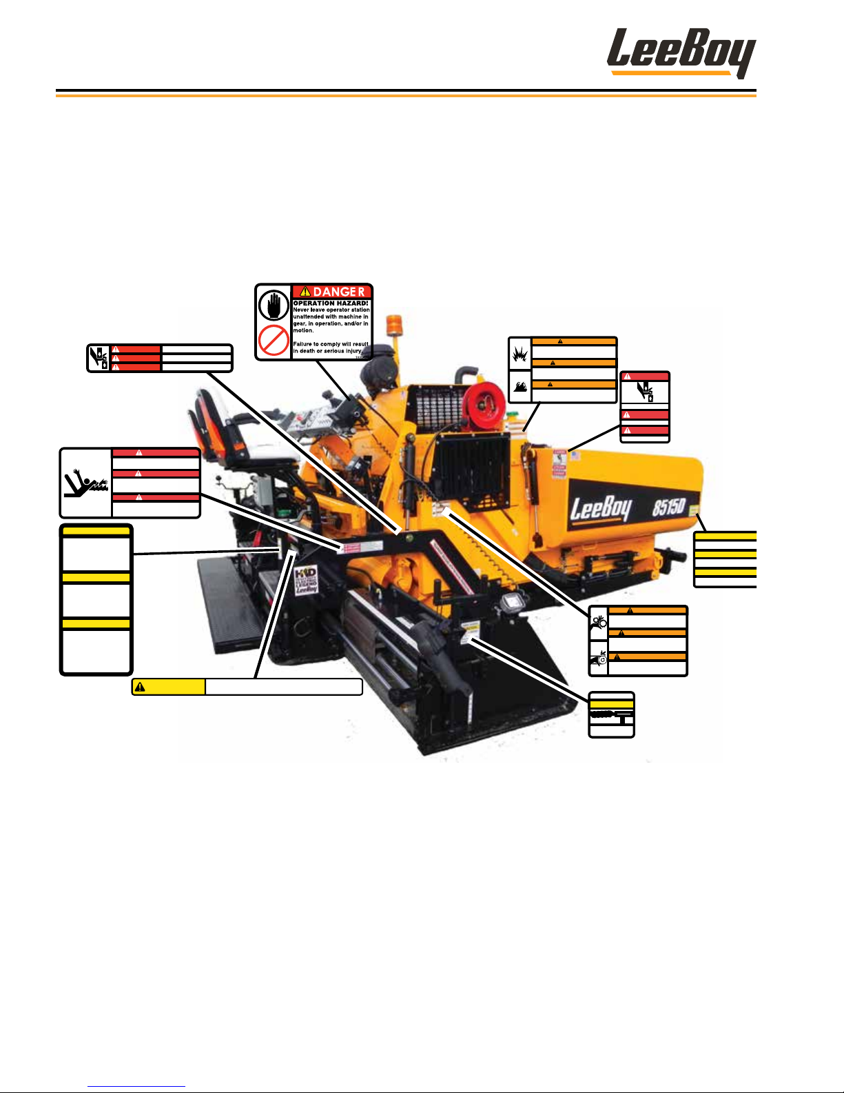
Safety Decals
If your machine is repainted, it is extremely important
that you replace all the CAUTION, WARNING and
DANGER safety decals in the proper locations. (Figure
1-1) For additional help, refer to the parts listing in
Section 7 and contact your authorized LeeBoy dealer to
order a replacement kit.
DANGER
PELIGRO
DANGER
ENTANGLEMENT HAZARD!
Keep hands and clothing clear of augers and conveyors.
Failure to comply will result in death or serious injury.
¡RIESGO DE QUEDAR ATRAPADO!
Mantener las manos y la ropa lejos de los sinfines y
transportadores. Si no se cumple con esta disposición, se
causará la muerte o lesiones graves.
RISQUE D'ENCHEVÊTREMENT !
Maintenir les mains et les vêtements à l’écart des vis et
convoyeurs. Le non-respect de cette règle entraînera des
856442
Flight screw handle must be in
locked position when raising
screed.
Damage may occur to hand, seat or
screw if not locked.
Always remove hand when raising
screed.
PRECAUCION
La manija del tornillo de recorrido
debe estar en la posición trabada
al elevar la plataforma. Se pueden
sufrir lesiones en la mano, o dañar
el asiento o tornillo si no está
trabada. Siempre quitar las manos
al elevar la plataforma.
La poignée de vis d’ailette doit
être en position verrouillée lors du
levage de la plaque de finition.
Une blessure à la main risque de
se produire et le siège ou la vis
d’être endommagé(e) si elle n’est
pas verrouillée. Toujours enlever
la main lors du levage de la
plaque de finition.
blessures graves, voire mortelles.
CAUTION
ATTENTION
856482
Both Sides
PINCH POINT
PUNTO DE APRIETE
POINT DE PINCEMENT
Both Sides
DANGER
PELIGRO
DANGER
Both Sides
CAUTION
856438
WATCH YOUR STEP!
Failure to comply may result in minor or moderate injury.
Both Sides
859789
NOTE: It is the responsibility of the owner and
operator to make sure that all safety labels are
readable and located on the paver as designated by
LeeBoy.
WARNING
EXPLOSION/FIRE HAZARD!
Do not use electric spray system when burners are in use.
Do not fill fuel tank when engine is running or screed is being heated.
Failure to comply could result in death or serious injury.
ADVERTENCIA
¡RIESGO DE EXPLOSION/INCENDIO!
No utilizar el sistema de rociado eléctrico cuando los quemadores están en uso.
No llenar el tanque de combustible con el motor en marcha o si se está calentando la
plataforma.
Both Sides
Si no se cumple con esta disposición, se puede causar la muerte o lesiones graves.
AVERTISSEMENT
RISQUE D’EXPLOSION/INCENDIE !
Ne pas utiliser le système électrique de pulvérisation lorsque les brûleurs sont allumés.
Ne pas faire le plein de carburant avec le moteur en marche ni pendant le réchauffage de
la plaque de finition.
Le non-respect de cette règle risque d’entraîner des blessures graves, voire mortelles.
856444
Both Sides
DANGER
PINCH POINT
PELIGRO
PUNTO DE APRIETE
DANGER
POINT DE PINCEMENT
Both Sides
WARNING
ENTANGLEMENT HAZARD!
Keep hands clear.
Keep guards in place. Replace missing guards or shields.
Failure to comply could result in death or serious injury.
ADVERTENCIA
¡RIESGO DE QUEDAR ATRAPADO!
Mantener las manos alejadas.
Mantener los protectores en su lugar. Sustituir los protectores o escudos
faltantes.
Si no se cumple con esta disposición, se puede causar la muerte o lesiones
graves.
AVERTISSEMENT
RISQUE D'ENCHEVÊTREMENT !
Ne pas approcher les mains.
Maintenir les protections en place. Remplacer les carters et protections qui
manquent.
Le non-respect de cette règle risque d’entraîner des blessures graves, voire
mortelles.
Both Sides
SONIC AUGERS
CAUTION
Ensure cord points
toward front.
859799
Both Sides
856437
73283-1
CAUTION
Keep guidebar latched when transportin
Keep all adjustments tight.
PRECAUCION
Mantener la barra guía trabada durante el trans
Mantener todos los ajustes bien apretados.
ATTENTION
Maintenir la barre de guidage verrouillée penda
transport. Maintenir tous les ajustements serré
Both Sides
Figure 1-1. Safety Labels and Safety Label Locations
LeeBoy 8515D Conveyor Paver1-10

Safety
Safety Decals Care
1. Keep safety decals and signs clean and legible at all
times.
2. Become familiar with the content and the position
of each safety decal. Decals include important
information.
3. Replace decals and signs that are missing or
become impossible to read.
4. When replacing parts that display a safety decal,
ensure that the new part is tted with a decal as well.
5. Obtain replacement safety decals or signs from
your authorized LeeBoy dealer.
Decal Installation (Sticker Type)
1. Be sure that the installation area is clean and dry.
Use hot, soapy water to clean the surface where the
decal will be applied.
2. Thoroughly dry the surface.
3. Measure and t decal before removing the paper
backing.
Decal Installation (Top
Protected)
1. If the decal has a protective top paper, use hot
soapy water on the surface where the decal will be
applied. Leave wet.
2. Determine the proper location, remove protective
back paper and soak decal in clean soapy water
before application. This will help to alleviate air
bubbles in the applied decal.
3. Smooth decal into place with a squeegee and check
for air bubbles.
4. Small air pockets can be pierced with a pin and
smoothed out using a piece of the decal backing.
5. When decal is completely smoothed, carefully
remove top paper.
1
4. For decals with no top protection paper, remove the
smallest split-backed paper.
5. Align decal over the specied area and carefully
press exposed portion into place.
6. Slowly remove the remaining backing and carefully
smooth the remaining portion of the decal into
place.
7. Small air pockets can be pierced with a pin and
smoothed using a piece of the decal backing.
LeeBoy 8515D Conveyor Paver 1-11

Safety
NOTES
LeeBoy 8515D Conveyor Paver1-12

Section 2
INFORMATION AND SPECIFICATIONS
Page
Limited Warranty Policy . . . . . . . . . . . . . . . . . . . . . . . . . . 2-2
Contact Information . . . . . . . . . . . . . . . . . . . . . . . . . . . . 2-3
Specications Charts. . . . . . . . . . . . . . . . . . . . . . . . . . . . 2-4
Torque Specications . . . . . . . . . . . . . . . . . . . . . . . . . . . 2-7
Standard Inch Fasteners . . . . . . . . . . . . . . . . . . . . . . . 2-7
Metric Fasteners . . . . . . . . . . . . . . . . . . . . . . . . . . . 2-8
Hydraulic Fittings . . . . . . . . . . . . . . . . . . . . . . . . . . 2-8
Determining Proper Torque . . . . . . . . . . . . . . . . . . . . . 2-9
8515D Conveyor Paver 2-1

Information and Specications
LIMITED WARRANTY POLICY
Warranty
Subject to the limitations, exclusions, and claims procedures set
forth herein, VT LeeBoy, Inc. warrants [to the rst retail purchaser]
that this product will be free from substantial defects in materials
and workmanship during the warranty period.
If a defect in material or workmanship is found, your authorized
LeeBoy Dealer is to be notied during the warranty period.
LeeBoy and its authorized Dealer will repair or replace any part or
component of the unit or part that fails to conform to the warranty
during the warranty period.
The warranty period will begin on the initial start-up, training and
delivery of the unit by the Dealer to the customer, and will expire
after twelve (12) months following the delivery of the product to the
rst retail purchaser. (See Dealer for additional warranty.)
Manufacturers’ Warranties: Engines are warranted by their
manufacturers and may have warranty coverage that differs from
that of LeeBoy. LeeBoy does not warrant any engine.
Replacement parts furnished by LeeBoy are covered for the
remainder of the warranty period applicable to the unit or
component in which such parts are installed.
LeeBoy has the right to repair any component or part before
replacing it with a new one.
All new replacement parts purchased by a LeeBoy Dealer will carry
a six-month warranty.
This Limited Warranty is governed by the laws of the State of North
Carolina.
THE FOREGOING WARRANTY IS EXCLUSIVE AND IN LIEU
OF ALL OTHER EXPRESSED, STATUTORY AND IMPLIED
WARRANTIES APPLICABLE TO UNITS, ENGINES, OR PARTS
INCLUDING WITHOUT LIMITATION, ALL IMPLIED WARRANTIES
OF MERCHANTABILITY OR FITNESS FOR ANY PARTICULAR USE
OR PURPOSE OR AGAINST INFRINGEMENT.
Items Not Covered
LeeBoy is not responsible for the following:
All used units or used parts of any kind.
Repairs due to normal wear and tear or brought about by abuse or
lack of maintenance of the machine.
Attachments not manufactured or installed by LeeBoy.
Liability for incidental or consequential damages of any type
including, but not limited to, lost prots or expenses of acquiring
replacement equipment.
Limitations
VT LeeBoy , Inc. has no obligation for:
Any defects caused by misuse, misapplication, negligence, accident,
or failure to maintain or use in accordance with the most current
operating instructions.
Unauthorized alterations.
Defects or failures caused by any replacement parts or attachments
not manufactured by or approved by LeeBoy.
Failure to conduct normal maintenance and operating service
including, without limitation, providing lubricants, coolant, fuel, tuneups, inspections, or adjustments.
Unreasonable delay, as established by LeeBoy, in making the
applicable units or parts available upon notication of a service notice
ordered by same.
Warranty Responsibility: The warranty responsibility on all engines
rests with the manufacturer of the engine.
Warranty and Parts Support: LeeBoy may have support agreements
with some engine manufacturers for warranty and parts support.
However, LeeBoy does not warrant the engine.
This Limited Warranty sets forth your sole remedy in connection
with the sale or use of the LeeBoy product covered by this Limited
Warranty.
This Limited Warranty extends only to the rst retail purchaser, and is
not transferable.
In the event any portion of this Limited Warranty shall be determined
to be invalid under any applicable law, such provision shall be deemed
null and void and the remainder of the Limited Warranty shall continue
in full force and effect.
Other Limitations
IN NO EVENT, WHETHER AS A RESULT OF BREACH OF CONTRACT
OR WARRANTY OR ALLEGED NEGLIGENCE OR LIABILITY WITHOUT
FAULT, SHALL LEEBOY BE LIABLE FOR SPECIAL, INCIDENTAL OR
CONSEQUENTIAL DAMAGES INCLUDING, WITHOUT LIMITATION,
LOSS OF PROFIT OR REVENUE, COST OF CAPITAL, COST
OF SUBSTITUTED EQUIPMENT, FACILITIES OR SERVICES,
DOWNTIME COSTS, LABOR COSTS OR CLAIMS OF CUSTOMERS,
PURCHASERS OR LESSEES FOR SUCH DAMAGES. IN NO EVENT
WILL WARRANTY COMPENSATION, OR OTHER DAMAGES
AVAILABLE FROM LEEBOY EXCEED THE PURCHASE PRICE OF
THE PRODUCT.
2-2
8515D Conveyor Paver
CONTACT INFORMATION
Information and Specications
For information regarding parts and repairs about
your LeeBoy product, contact your authorized LeeBoy
dealer. If your dealer is unable to resolve the problem,
contact LeeBoy directly.
Sales Representative:
Dealership Name:
Dealership Address:
Dealership Phone:
Record dealer information in the space provided.
For additional information about LeeBoy, please visit:
www.leeboy.com.
Record of Ownership
Please complete the following information for use if you need to contact LeeBoy for service, parts or literature.
Machine Model Number:
Product Serial Number:
Date of Purchase:
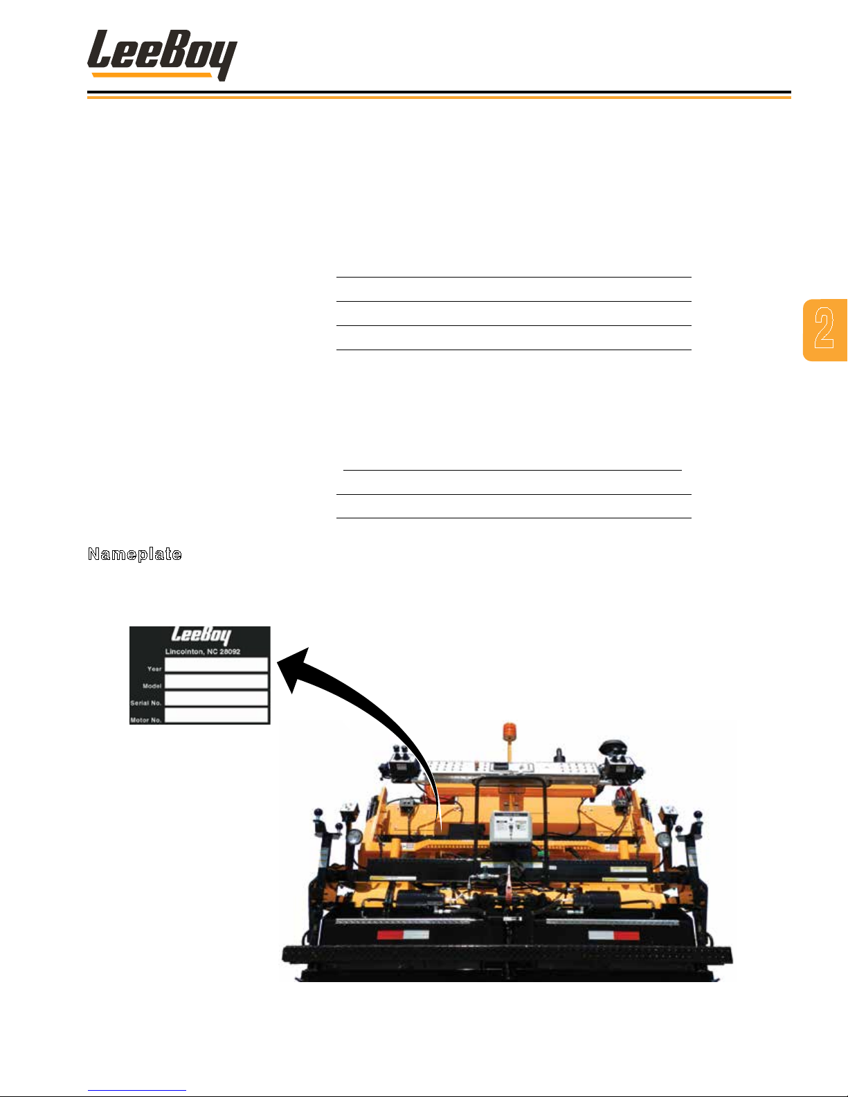
Nameplate
2
The nameplate contains the model and serial numbers used to identify the machine and its components for parts or
service information. Refer to the Engine Operator’s Manual for the location of the engine nameplate.
8515D Conveyor Paver
Figure 2-1. Nameplate Location
2-3
Information and Specications
SPECIFICATION CHARTS
The specications provided in this section include
screed weights, dimensions, performance, and torque
values for both metric and standard inch fastener.
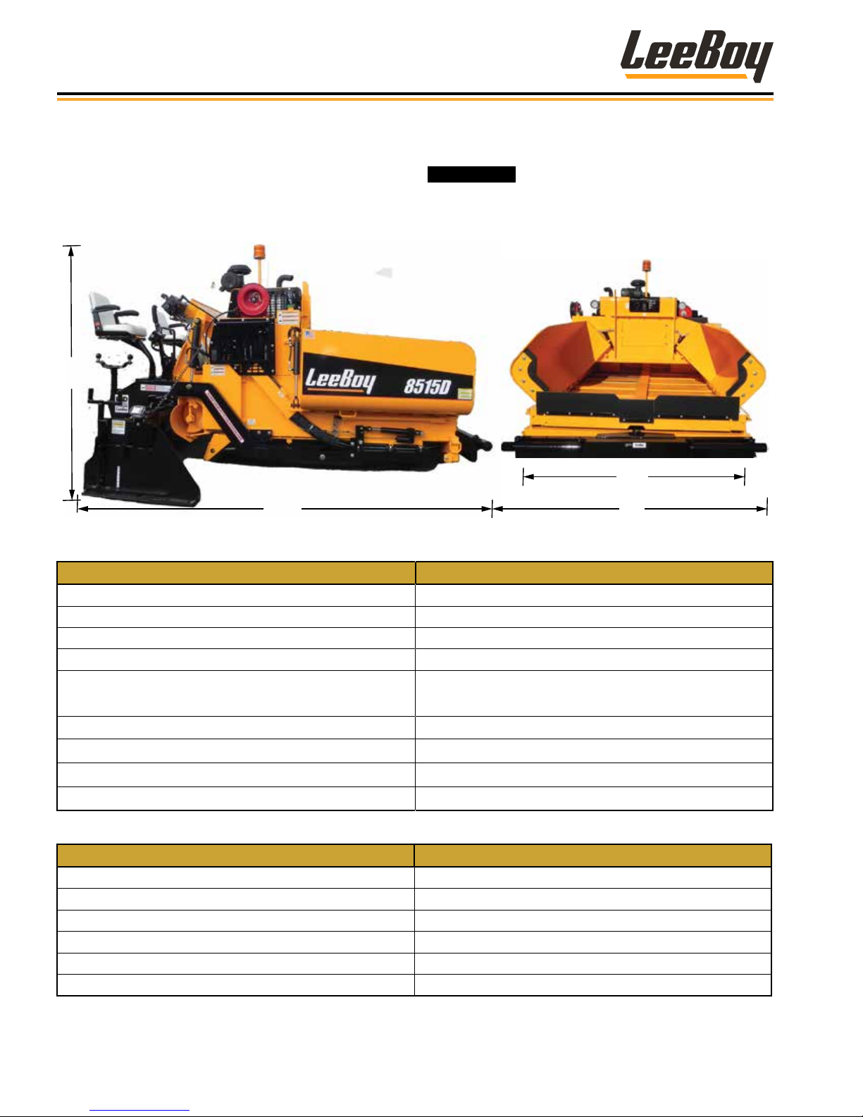
8’ 3”
13’ 3”
Table 2-1. Machine Dimensions
ITEM SPECIFICATION
Overall Length 13 ft 3 in (4 m)
Overall Height 8 ft 6 in (2.6 m)
Overall Width (Hopper Wings In) 8 ft 6 in (2.6 m)
Overall Width (Hopper Wings Out) 10 ft (3 m)
Overall Weight
Paving Width 8 - 15 ft (2.4 - 4.6 m)
Extensions Length 3 ft 6 in (30 cm)
components approved by your LeeBoy dealer.
Standard Screed: 17,500 lb (7937 kg)
HD Screed Option: 17,900 (8119 kg)
Replace original equipment only with
8’ 6”
10’
Main Screed Wear Plate
Extension Width of Wear Plate 7” (17.8 cm)
ITEM SPECIFICATION
Manufacturer and Model Kubota, V3800-CR-TE4B, Tier 4 (Final)
Engine Type Vertical Liquid Cooled Diesel, 4-Cylinder
Bore, Stroke and Displacement 3.9 in (100 mm); 4.72 in (120 mm); 230 cu in (3.8 L)
Power Rating 74 HP (55.2 kW)
Intake and Combustion Systems Turbo-Charged, Direct-Injection
Maximum Speed 2200 RPMs
2-4
15” (38 cm)
Table 2-2. Engine Specications
8515D Conveyor Paver

Information and Specications
Table 2-3. Performance Specications
ITEM SPECIFICATION
Travel Speed
Paving Speed 0 - 140 FPM [0 - 2.4 MPM]
Table 2-5. Electrical Specications
ITEM SPECIFICATION
Battery 12 Vdc Maintenance Free, 12 Volts
Cold Cranking Amps (CCA) 1125 CCA
Alternator 12-Volt, Negative-Ground, 60 Amps
Alternator Fan Belt Tension
Starter Voltage and Type 12-Volt, Negative-Ground
Table 2-6. Lubricant Specications
ITEM SPECIFICATION
Engine Oil 15W-40, API, CH-4, CI-4
Hydraulic Oil All-Weather 68
Torque Hub 50 WT Gear Oil
Grease Shell Avania EP Grease or Equivalent
Chain Lube Chain Lube Agent
0 - 230 feet per minute (FPM)
[0 - 3.9 meters per minute (MPM)].
Manual belt tension mechanism keeps serpentine belt
under tension at all times.
2
Table 2-7. Machine System Capacity Specications
ITEM SPECIFICATION
Engine Lubrication Oil (Rell Capacity) 15 qts (14.2 L)
Hydraulic Oil Tank 40 gal (151.4 L)
Torque Hubs 32 oz (.35 L) each
Diesel Fuel 18 gal (68.1 L)
Propane One (1) 20-lb Tank
Antifreeze Glycol-Based, Extended Life; 3.6 gal (13.8 L)
Table 2-8. Hydraulic Pressures Specications
ITEM SPECIFICATION
Drive 3625 psi (249.9 Bar)
Conveyors and Cylinders 2500 - 2700 psi (172.3 - 179.2 Bar)
Augers 2800 - 3000 psi (193 - 206.8 Bar)
Track Tensioning Relief 1500 psi (103.4 Bar)
Charge Pressure 350 - 400 psi (24 - 27.6 Bar)
8515D Conveyor Paver
2-5

Information and Specications
Table 2-9. Hopper Specications
ITEM SPECIFICATION
Size 7.5 Tons (6804 kg)
Height 23 in (584 mm)
Wings 3/8 in (10 mm)
Figure 2-10. Screed Specications
ITEM SPECIFICATION
Screed Weight
Electric Heat (Option)
Propane Heat
Extensions Two (2) 44-inch Hydraulically-Operated
Vibration Two (2) hydraulic vibrators producing 2400 vpm.
Crown/Valley Adjustable, 2-inch crown, 1-1/2 inch of valley
Standard Screed 815HD (Option)
3000 lbs (1360 kg) 3700 lbs (1678 kg)
Two (2) 3412 BTU/hr
electric heat elements on
main screed.
One (1) 3412 BTU/hr
electric heat element on
each extension.
Two (2) 54,000 BTU propane burners on main screed.
One (1) 45,000 BTU propane burner on each extension.
Four (4) 3412 BTU/hr and
one (1) 820 BTU/hr electric
heat elements on main
screed.
One (1) 3412 BTU/hr
electric heat element on
each extension.
Table 2-11. Generator Specications (Electric Heat Option)
ITEM SPECIFICATION
Power 6.5 kW
Voltage 220 Volts
Frequency 60 Hz
2-6
8515D Conveyor Paver

Information and Specications
TORQUE SPECIFICATIONS
The following tables list torque values for standard
hardware. This is a guide for average application
involving typical stresses and machined surfaces.
Values are based upon physical limitations of clean,
plated and lubricated hardware. Under more extreme
conditions, individual torque value should be followed.
Conversion formulas are provided below:
that are not equal in size and grade to the original
equipment.
ft-lb to N•m [ft-lb]*1.3558 = [N•m)
ft-lb to in-lb [ft-lb]*12 = [in-lb]
N•m to in-lb [N•m]*8.8508 = [in-lb]
Never substitute fasteners of any kind
Conversion Formula
Standard Inch Fasteners
Table 2-13. Torque Specications For Standard Inch Fasteners
CAPSCREWS: SAE GRADE 5 CAPSCREWS: SAE GRADE 8
SIZE THREAD
1/4 20 UNC 8 6 11 8 12 9 16 12
28 UNF 10 7 14 9 14 10 19 14
5/16 18 UNC 17 13 23 18 25 18 34 24
24 UNF 19 15 26 20 27 20 37 27
3/8 16 UNC 31 23 42 31 44 33 60 45
24 UNF 35 26 47 35 49 37 66 50
7/16 14 UNC 49 37 66 50 70 52 95 71
20 UNF 55 41 75 56 78 58 106 79
1/2 13 UNC 75 57 102 77 106 80 144 108
20 UNF 85 64 115 87 120 90 163 122
9/16 12 UNC 109 82 148 111 154 115 209 156
18 UNF 121 91 164 123 171 128 232 174
5/8 11 UNC 150 113 203 153 212 159 287 216
18 UNF 170 127 230 172 240 180 325 244
3/4 10 UNC 267 200 362 271 376 282 510 382
16 UNF 297 223 403 302 420 315 569 427
7/8 9 UNC 429 322 582 437 606 455 822 617
14 UNF 474 355 643 481 669 502 907 681
1 8 UNC 644 483 873 655 909 681 1232 923
14 UNF 722 542 979 735 1020 765 1383 1037
1-1/4 7 UNC 1121 840 1520 1139 1817 1363 2464 1848
12 UNF 1241 930 1683 1261 2012 1509 2728 2046
1-1/2 6 UNC 1950 1462 2644 1982 3162 2371 4287 3215
12 UNF 2194 1645 2975 2230 3557 2668 4823 3617
TORQUE (ft lb) TORQUE N•m TORQUE (ft lb) TORQUE N•m
Dry Lubed Dry Lubed Dry Lubed Dry Lubed
2
8515D Conveyor Paver
2-7

Information and Specications
Metric Fasteners
Table 2-14. Torque Specications for Metric Fasteners
CLASS 8.8 [GRADE 5 EQUIVALENT] CLASS 10.9 [GRADE 8 EQUIVALENT]
NOMINAL SIZE
AND PITCH
M4 x 0.7 2 2 3 2 3 2 4 3
M5 x 0.8 5 3 7 4 7 5 9 7
M6 x 1 8 6 11 8 11 8 15 11
M8 x 1.25 19 14 26 19 27 20 37 27
M10 x 1.5 37 28 50 38 53 40 72 54
M12 x 1.75 65 49 88 66 93 70 126 95
M14 x 2 104 78 141 106 148 111 201 150
M16 x 2 161 121 218 164 230 173 312 235
M18 x 2.5 222 167 301 226 318 239 431 324
M20 x 2.5 314 236 426 320 449 337 609 457
M22 x 2.5 428 321 580 435 613 460 831 624
M24 x 3 543 407 736 552 777 582 1053 789
M27 x 3 796 597 1079 809 1139 854 1544 1158
M30 x 3.5 1079 809 1463 1097 1544 1158 2093 1570
TORQUE (ft lb) TORQUE N•m TORQUE (ft lb) TORQUE N•m
Dry Lubed Dry Lubed Dry Lubed Dry Lubed
Hydraulic Fittings
Tightening Flare-Type Tube Fittings
1. Check the are and are seat for defects that might
cause leakage.
2. Align tube with tting before tightening.
3. Lubricate connection.
4. Hand tighten swivel nut until snug.
5. To prevent twisting the tube(s), use two wrenches.
Place one wrench on the connector body and
tighten the swivel nut with the second to the torque
shown in the following table:
NOTE: The torque values shown are based upon
lubricated connections.
Table 2-15. Torque Specications for Steel Flare
Type Tube Fittings
TUBE SIZE
OUTER
DIAMETER
(IN) (IN) (LB FT) (N•m)
3/16 7/16 8 11
1/4 9/16 12 16
5/16 5/8 16 22
3/8 11/16 23 31
1/2 7/8 38 52
5/8 1 54 73
3/4 1 1/4 75 102
7/8 1 3/8 83 113
NUT SIZE
ACROSS
FLATS
TORQUE VALUE
2-8
8515D Conveyor Paver

Determining Proper Torque
LA
L
E
LA
LH
The only reliable method of creating a consistently
leak-free and long-lasting connection is to ensure the
coupling is brought to the proper torque. Using a torque
wrench with crowfoot is the best method, but the ats
method can be used if a torque wrench is not available.
The most straightforward method of determining the
correct torque setting is to multiply the desired torque
by the length of the wrench from the center of the handle
to the center of the drive (L); divided by the length of the
wrench from the center of the handle to the crowfoot
center (LA) as shown below:
L
Figure 2-16. Torque Wrench - Crowfoot
Information and Specications
2
The minimum torque values are
adequate for sealing most applications. Maximum
torque values should never be exceeded.
There are several methods of determining the correct
setting on the torque wrench when using a crowfoot. All
of the methods involve making the setting proportional
to the effective change in length of the wrench multiplied
by the desired nal torque. The equations and
illustration below describe proper measurements.
Equations
• Torque setting if the crowfoot is placed in line with
respect to the wrench:
• Torque setting if the crowfoot is placed at 90° with
respect to the wrench
• To estimate the crowfoot size (E)
TS = TD * L / LA
OR
TS = TD * L / (L+E)
TS = TD * L / LH
OR
TS = TD * L / √(L2 + E2)
Figure 2-17. Measurements Needed
LEGEND
L = Distance from center of torque wrench handle to the
center of socket drive
E = Distance from center of socket drive to the center of
crowfoot
LA = Distance from center of torque wrench handle to
the center of crowfoot
LH = Distance from center of torque wrench handle to
the center of crowfoot, when mounted at 90°
TD = Desired torque at the tting
TS = Torque setting indicated on wrench
E = Drive Size * 0.5 + Distance between Drive and
Open End + Wrench Size * 0.5774
8515D Conveyor Paver
2-9

Mark Line on Nut
Information and Specications
Coupling Installation
Use the following steps for proper coupling installation:
1. Determine the correct torque value for your
coupling.
NOTE: Only use the torque values specied from
the manufacturer. DO NOT use SAE torque
recommendations.
2. Ensure the seal face and threads are clean and in
good condition. O-Rings should be lubricated with
light oil, but threads should be completely dry unless
making pipe thread connections (interference seal).
NOTE: Attach the male end of the hose onto the
equipment rst since it may be necessary to
rotate the entire hose assembly to tighten
the male threads. Then route the hose into
position while avoiding twisting the hose.
3. Tighten the connection (by hand), bringing the seal
face into contact and rotating the nut until it stops.
4. Mark a line across the coupling nut and backup hex
for the ats method verication of coupling torque.
5. Apply a wrench to the backup hex to prevent the
coupling and hose from moving while tightening the
nut with a torque wrench.
Failure to retain the backup hex during
installation will also result in additional clamp load
force that could cause damage to the seal face.
NOTE: The coupling nut must be in motion for an
accurate torque reading. If the nut is stopped
before nal torque value is achieved, it must
be loosened and retightened until the torque
is attained while the nut is in motion.
If a torque wrench cannot t into the coupling area or if
it is unavailable, the ats method may be used to ensure
that the coupling is properly tightened, as shown in the
following gure.
Example 2 Flats
difference
Figure 2-18. Flats Method Tightening
NOTE: The mark placed on the nut and backup hex
after tightening by hand should rotate during
nal tightening according to the table below.
The nut and backup hex can then be marked
to indicate if the coupling loosens over time.
Table 2-19. Flats Method Values for Selected
Terminations
FLATS METHOD VALUES
Termination
Type
JIC -4 1.5 - 1.75
JIC -6 1.0 - 1.5
JIC -8 1.5 - 1.75
JIC -10 1.0 - 1.5
JIC -12 1.0 - 1.5
JIC -16 .75 - 1.0
JIC -20 .75 - 1.0
JIC -24 .75 - 1.0
JIC -32 .75 - 1.0
JIS -4 .5 - 1.5
1. Seal faces must be in contact with the tting fully
tightened by hand before marking ats.
2. The ats method is most accurate for the rst
assembly cycle. For multiple disassembly and
assembly cycles, torque values are more reliable.
Dash Size Flats
2-10
3. Tightening two (2) ats or more may damage seal
faces.
8515D Conveyor Paver

Information and Specications
Table 2-20. Torque Specications For US Style Coupling Terminations
JIC, SAE 45°, ORFS, O-RING BOSS, GATES ADAPTERLESS AND MEGASEAL
JIC 37°, SAE 45°
DASH
SIZE
-3 8 10
-4 10 11 5 6 10 12 14 16 14 16
-5 13 15 7 9 18 20
-6 17 19 12 15 18 20 24 26 24 26
-8 34 38 20 24 32 40 37 44 50 60
-10 50 56 34 40 46 56 50 60 72 80
-12 70 78 53 60 65 80 75 83 125 135
-14 65 80 160 180
-16 94 104 74 82 92 105 111 125 200 220
-20 124 138 75 83 125 140 133 152 210 280
-24 156 173 79 87 150 180 156 184 270 360
-32 219 243 158 175
& Mega-Seal
(Steel)
Min Max Min Max Min Max Min Max Min Max
JIC 37°, SAE 45°
& Mega-Seal
(Brass)
Flat Face O-Ring
Seal (Steel)
SAE O-Ring Boss
(Steel) & Gates
Adapterless
≤ 4000 PSI
SAE O-Ring Boss
(Steel) & Gates
Adapterless
> 4000 PSI
2
Table 2-21. Torque Specications for DIN 24, DIN
60, and Inverted Cone Style Coupling Terminations
DIN 24, DIN 60, AND INVERTED CONE
Size (mm) Torque (lb ft)
Light
Series
Tube OD
6 7 15
8 15 26
10 8 18 30
12 10 22 33
14 12 26 37
15 14 30 52
18 20 44 74
22 25 59 89
28 30 74 111
35 133 184
42 148 221
Heavy
Series
Tube OD
16 30 52
38 74 162
Min Max
Table 2-22. Torque Specications for 4-Bolt
Flange Connections
4-BOLT FLANGES
Dash Size Bolt Size (in) Torque (lb ft)
-8 0.31 17
-12 0.38 26
-16 0.44 43
-20 0.50 65
-24 0.63 130
-32 0.75 220
1. Align faces and tighten bolts (by hand) before
applying nal torque in a pattern. The seal faces
must be parallel with an even bolt tension to seal
properly.
2. Torque values apply to bolts that are plated or
coated in light engine oil.
3. Before assembly, lubricate O-Ring with light oil
(SAE 10W or 20W).
8515D Conveyor Paver
2-11

Information and Specications
Table 2-23. Torque Specications for NPTF Dry Seal
Pipe Threads
NPTF
Dash Size Max Torque (ft-lb)
-2 20
-4 25
-6 35
-8 45
-12 55
-16 65
-20 80
-24 95
-32 120
1. The torque values obtained from tightening pipe
threads can vary considerably depending upon
thread condition. Adequate sealing can occur at
values much lower than the maximum values listed
above. Only enough torque to achieve adequate
sealing should be used.
2. When using a male tapered pipe thread with a
female straight or parallel pipe thread, maximum
values are 50% of those listed in the table above.
Table 2-24. Torque Specications for BSP 30°
Inverted Cone and JIS Coupling Terminations
BSP 30° INVERTED CONE AND JIS
Torque (ft-lb)
Dash Size
Min Max
-2 7 9
-4 11 18
-6 19 28
-8 30 36
-10 37 44
-12 50 60
-16 79 95
-20 127 152
-24 167 190
-32 262 314
3. If thread sealant is used, maximum values shown
should be decreased by 25%.
2-12
8515D Conveyor Paver

Section 3
COMPONENT LOCATION
Page
Component Location . . . . . . . . . . . . . . . . . . . . . . . . . . . . . 3-1
Components Overview . . . . . . . . . . . . . . . . . . . . . . . . . . . 3-3
Hydraulic System . . . . . . . . . . . . . . . . . . . . . . . . . . 3-3
Hopper and Conveyors . . . . . . . . . . . . . . . . . . . . . . . 3-3
Augers . . . . . . . . . . . . . . . . . . . . . . . . . . . . . . . . 3-4
Operator Platform . . . . . . . . . . . . . . . . . . . . . . . . . . 3-4
Screed . . . . . . . . . . . . . . . . . . . . . . . . . . . . . . . 3-4
Electrical System . . . . . . . . . . . . . . . . . . . . . . . . . . 3-4
Standard Equipment/Options . . . . . . . . . . . . . . . . . . . . 3-4
Machine Overview . . . . . . . . . . . . . . . . . . . . . . . . . . . . . 3-5
Left Control Panel . . . . . . . . . . . . . . . . . . . . . . . . . . . . . 3-6
Right Control Panel. . . . . . . . . . . . . . . . . . . . . . . . . . . . . 3-8
Center Control Panel . . . . . . . . . . . . . . . . . . . . . . . . . . . . 3-10
Steering and Speed Control Box . . . . . . . . . . . . . . . . . . . . . . 3-11
Screed Controls . . . . . . . . . . . . . . . . . . . . . . . . . . . . . . 3-12
Burner Controls . . . . . . . . . . . . . . . . . . . . . . . . . . . . . . 3-13
3
Propane Tank Controls . . . . . . . . . . . . . . . . . . . . . . . 3-13
Steering Wheel (Option) . . . . . . . . . . . . . . . . . . . . . . . . . . 3-14
Electric Heat (Option) . . . . . . . . . . . . . . . . . . . . . . . . . . . 3-14
Leeboy Model 8515D Conveyor Paver 3-1

Component Location
NOTES
Leeboy Model 8515D Conveyor Paver3-2

Component Location
Components Overview
This section describes the major components for the
LeeBoy 8515D Conveyor Paver. Become familiar with
these components before operating the machine.
Engine
The LeeBoy Model 8515D Conveyor Paver is equipped
with a Kubota, 74 HP (55.2 kW) diesel engine mounted
on standard heavy-duty vibration isolators. It is
accessible through several access doors on the engine
cover, especially the front service door mounted with
all fuel lter components for easier access. This paver
features improved visibility with a low-prole engine
cover along with easy access to engine relays and the
fuse panel.
The air cleaner removes ne particles such as dust,
sand, chaff and lint from the air. As air is taken into the
air cleaner assembly, the cyclone action deposits some
of the ne particles in the evacuator that is mounted on
the bottom of the air cleaner housing. The evacuator is
held closed during engine operation by suction. When
the engine is shut off, the weight of the debris opens
rubber aps, allowing the debris to fall out. These aps
can also be squeezed open for cleaning.
Hydraulic System
The hydraulic system includes hydraulic pumps, motor
and cylinders that work together for optimum machine
component control. Valves regulate the directional,
pressure and uid ow throughout the hydraulic system.
The LeeBoy 8515D Conveyor Paver now features
a hydraulic test ports for ease and convenience in
checking pressure for its ve main functions.
Torque Hubs
The paver drive system contains two torque hubs that
provide power to propel the tracks. Two-speed motors
power tough planetary drives for smooth operation.
Hopper and Conveyors
The hopper wings are hydraulically controlled to raise
and lower the hopper. When fully open, the hopper can
hold a payload up to 7.5 tons.
Material in the hopper is moved toward the back of the
paver to the screed by conveyors. The conveyor is
activated at the operator platform. Its wide, automatic
conveyors with a wide hopper design delivers asphalt
more evenly and efciently to produce a smooth asphalt
mat.
The hopper’s conveyor bed can be lifted hydraulically,
allowing easy access to the paver undercarriage and
tracks for service and cleaning.
3
The fuel lter removes contaminants from diesel fuel
before it ows into the injection pump where it is injected
into the engine combustion chamber.
The radiator mounted in front of the engine cools the
engine. As coolant ows through the radiator, airow
from the engine-driven fan removes heat.
Refer to the Engine Operator’s Manual accompanying
your paver for additional engine information.
Leeboy Model 8515D Conveyor Paver 3-3

Component Location
Augers
Right and left augers rotate
to move material from the
conveyors to the screed.
The auger can be manually
controlled at the operator
platform or by a screed
operator on the screed using a remote control box.
The auger can also be controlled automatically using
the auger sonic sensor system. The sensor is mounted
on the screed endgates and used to monitor and control
the pile height of material at the discharge end of the
augers.
Operator Platform
The operator platform allows easy and convenient
access for controls of most paver functions. The paver
can be operated from the left or right side depending
upon which control panel side is active and best suited
to the working conditions. Controls can also be lowered
to operate as a low deck or the high deck option with an
assistant standing on the screed walkboard.
Electrical System
The battery produces 12 volts DC and maintains 1,125
cold cranking amperes (CCA). An engine-mounted
alternator with a minimum of 60 amperes charging
capacity keeps the battery charged during normal
operation. The battery charge rate can be monitored
using the voltmeter on the center operator control panel.
Standard Equipment/Options
Component
8 - 15 feet (2.44 - 4.57 m) Propane Screed
Two-Speed Hydrostatic Drive
Under Auger Cut-Off Gates
Light and Safety Beacon Package
12-inch (30.5 cm) Augers w/Sonic Control
Dual Operator Stations
Dual 2400 vpm Vibrators
Citrus Tank
Anti-Vandalism Package
Legend Electric Screed Option
Legend 815HD Electric Screed Option
Dual Grade Control Option
Dual Grade and Slope Control Option
Truck Hitch Option
Sloping Extensions Option
Power Crown Option
Steering Wheel Option
Roll-Up Curb Attachment Option
Heated End Gates Option
v
v
v
v
v
v
v
v
v
Screed
The screed is the last part of the paver that contacts the
paving material. A screed operator usually operates the
screed while the operator drives the machine. Paving
material is fed from the hopper and conveyor to the
augers to the front of the screed.
The screed has hydraulically-controlled extensions that
move in and out to allow a paving base from 8 - 15 feet.
Screed heating is accomplished by either propane or
the optional electric heating elements mounted directly
to the wear plates.
3-4 Leeboy Model 8515D Conveyor Paver

Machine Overview
Component Location
5
4
3
2
6
7
3
1
8
9
10
Figure 3-1. Machine Overview
ITEM
NO.
1 Crown and Valley
2 Main Screed Depth Screw
3 Operator Control Panel
4 Joysticks
5 Beacon Light
6 Spray Down Hose Reel
7 Hopper
8 Sonic Auger Sensor Senses and automatically gauges the amount of material in the extensions.
9 Endgate Depth Screw Controls depth of the screed endgate.
10 Screed Extension
CONTROL NAME FUNCTION
Adjusts crown and valley while paving.
Controls depth of the asphalt (located on each side).
Machine and operator controls.
Controls travel direction and speed (on each side of machine).
Revolving amber safety light to alert trafc and others at the work site.
Sprays releasing agent to lubricate and prevent asphalt from hardening on
machine surfaces.
Hopper wings fold out to hold asphalt material.
Extends for a paving width from 8 - 15 feet.
Leeboy Model 8515D Conveyor Paver 3-5

Component Location
Left Control Panel
The operator control console for the LeeBoy
8515D Conveyor Paver offers the convenience
of operating from either side depending upon
working conditions. The control panel has a cover
for protection from the elements.
While operators typically pave on the left side of
the machine, a complete set of controls on the
right control panel allows operators the exibility of
working from either side.
1
9
10
11
12
2
5
4
3
13
6
7
14
8
16
15
Figure 3-2. Operator Control Panel
ITEM
NO.
1
2
3
CONTROL
NAME
Right Auger
Switch
Right Conveyor
Switch
Left Screw
Thicker/Thinner
Switch
FUNCTION
Selects ON or OFF for automatic operation of right auger. Center position is OFF. Selecting
MANUAL position provides manual override.
NOTE: Set the left and right auger switches on the right control panel to the SLAVE position
when operating from the left side. (Figure 3-3)
NOTE: If using the sonic auger, ensure the left and right auger switches on the right control
panel are in the SLAVE position; and the left and right Auger AUTOMATIC/MANUAL
switches are set to the AUTO position (left control panel).
NOTE: The Auger On/Off switch on both remote control boxes must be set to the ON position.
(Page 4-26)
Selects automatic or manual mode for right conveyor. MANUAL position provides override.
Conveyor can be operated from either side of the control panel in the MANUAL mode. The center
position is OFF. For automatic operation, set switch to AUTOMATIC.
Sets the thickness of the asphalt. Operator can select either THICKER or THINNER as needed.
The Grade Control switch must be set to GRADE on both sides of the control panel to turn power
on for this feature.
3-6 Leeboy Model 8515D Conveyor Paver

Component Location
ITEM
NO.
4
5 Vibrator Switch
6
7
8
9 Left Auger Switch
10
11
12 Left Cut-Off Gate
13
14 Sidewings Switch
15
16 High Gear Light Illuminates when paver is in high gear.
CONTROL
NAME
Screed Lift/Float
Switch
High/Low
2-Speed Gear
Switch
Grade Control
Switch
Truck Hitch
(Option)
Left Conveyor
Switch
Left Extension
Switch
Right Cut-Off
Gate
Right Extension
Switch
Raises or oats the screed. When released, switch automatically returns to the center to hold the
screed in selected position. Flip switch to RAISE to raise the screed. Set the switch to FLOAT to
oat the screed (switch will lock in the FLOAT position).
NOTE: The screed will not raise if this switch is set to FLOAT on one side of the control panel
and RAISE on the other.
Turns the screed vibrator on and off, but only functions when joysticks are in the forward position.
The screed vibrator helps compact material.
Used to change machine speed. Place switch in HIGH position for travel (High/Low Gear light will
illuminate). Pave only in LOW speed. NEVER pave in high speed as serious injury can result. The
High/Low Gear switch on both sides must be in the LOW position to function.
When this switch is in the GRADE position, the power is ON regardless of the joystick position.
The left control panel switch selects manual or automatic mode. The Grade Control switch on the
right control panel must be in the ON position to operate.
Optional Component: Engages truck hitch function. Engages the truck hitch to the material truck
wheels. Set switch to the IN position to engage the hitch. The OUT position disengages hitch from
the material truck wheels.
NOTE: If equipped with truck hitch option, set the selector lever on the hitch component to
the TRUCK HITCH position. (Page 4-33) (If this lever is set to CONVEYOR, it will
raise and lower the conveyor bed.)
Selects ON or OFF for automatic operation of left auger.
NOTE: Set the left and right auger switches on the right control panel to the SLAVE position
when operating from the left side. (Figure 3-3)
NOTE: If using the sonic auger, ensure the left and right auger switches on the right control
panel are in the SLAVE position and the left and right Auger AUTOMATIC/MANUAL
switches are set to the AUTO position (left control panel).
NOTE: The Auger On/Off switch on both remote control boxes must be set to the ON position.
(Page 4-26)
Selects automatic or manual mode for left conveyor. MANUAL position provides override.
Conveyor can be operated from either side of the control panel in the MANUAL mode. The center
position is OFF. For automatic operation, set switch to AUTOMATIC.
Extends or retracts left screed extension. (Switch also located on the remote box on left side of
paver.) Push switch IN to retract left screed extension. Push switch to OUT to extend left screed
extension.
Opens and closes left cut-off gate. The cut-off can be operated from either side of the control
panel.
Opens and closes right cut-off gate. The cut-off can be operated from either side of the control
panel.
Opens and closes hopper sidewings. Push switch to the OUT position to open hopper wings.
Push switch to the IN position to close hopper wings.
Extends or retracts right screed extension. (Switch also located on the remote control box. (Page
4-26) Push switch IN to retract right screed extension. Push switch to OUT to extend right screed
extension.
FUNCTION
3
Leeboy Model 8515D Conveyor Paver 3-7

Component Location
1 2 3 4 5 6
7
8 9 10 11 12 13
14
15 16
Right Control Panel
The right side control panel contains the same
paving component controls as the left side for
operator convenience, i.e., conveyor, auger,
hopper wings, etc. The switches are in reverse
order from the left side of the control panel, with
additional control features for auger operation.
some switches work in conjunction with each
other on both sides of the control panel,
especially auger operation and the optional truck
hitch component.
Figure 3-3. Right Control Panel
ITEM
NO.
1 Truck Hitch (Option)
2 Grade Control Switch Selects automatic or manual mode for right conveyor. MANUAL position provides override.
3 Vibrator Switch
4
CONTROL NAME FUNCTION
Optional Component: Engages truck hitch function. Engages the truck hitch to the
material truck wheels. Set switch to the IN position to engage the hitch. The OUT position
Right Screw Thicker/
Thinner Switch
disengages hitch from the material truck wheels.
NOTE: If equipped with truck hitch option, set the selector lever on the hitch component
to the TRUCK HITCH position. (Page 4-33) (If this lever is set to CONVEYOR, it
will raise and lower the conveyor bed.)
Turns the screed vibrator on and off, but only functions when joysticks are in the forward
position. The screed vibrator helps compact material.
Sets the thickness of the asphalt. Operator can select either THICKER or THINNER as
needed. The Grade Control switch must be set to GRADE on both sides of the control panel
to turn power on for this feature.
3-8 Leeboy Model 8515D Conveyor Paver

Component Location
ITEM
NO.
5
6
7 High Gear Light Illuminates when paver is in high gear.
8 Right Extension Switch
9
10 Sidewings Switch
11 Screed Lift/Float Switch
12 Left Cut-Off Gate
13 Left Conveyor Switch
14 Right Cut-Off Gate
15 Right Conveyor Switch
16 High Gear Light Illuminates when paver is in high gear.
CONTROL NAME FUNCTION
Selects ON or OFF for automatic operation of left auger. Center position is OFF. Selecting
MANUAL position provides manual override. Select SLAVE for automatic operation.
NOTE: Set the left and right auger switches on the right control panel to the SLAVE
Left Auger Manual/
Slave Switch
Right Auger Manual/
Slave Switch
High/Low 2-Speed
Gear Switch
NOTE: If using the sonic auger, ensure the left and right auger switches on the
NOTE: The Auger On/Off switch on both remote control boxes must be set to the ON
Selects ON or OFF for automatic operation of right auger. Center position is OFF. Selecting
MANUAL position provides manual override. Select SLAVE for automatic operation.
NOTE: Set the left and right auger switches on the right control panel to the SLAVE
NOTE: If using the sonic auger, ensure the left and right auger switches on the
Extends or retracts right screed extension. (Switch also located on the remote control box.
(Page 4-26) Push switch IN to retract right screed extension. Push switch to OUT to extend
right screed extension.
Used to change machine speed. Place switch in HIGH position for travel (High/Low Gear
light will illuminate). Pave only in LOW speed. NEVER pave in high speed as serious injury
can result. The High/Low Gear switch on both sides must be in the LOW position to function.
Opens and closes hopper sidewings. Push switch to the OUT position to open hopper
wings. Push switch to the IN position to close hopper wings.
Raises or oats the screed. When released, switch automatically returns to the center to
hold the screed in selected position. Flip switch to RAISE to raise the screed. Set the switch
to FLOAT to oat the screed (switch will lock in the FLOAT position).
NOTE: The screed will not raise if this switch is set to FLOAT on one side of the control
Opens and closes left cut-off gate. The cut-off can be operated from either side of the
control panel.
Selects automatic or manual mode for left conveyor. MANUAL position provides override.
Conveyor can be operated from either side of the control panel in the MANUAL mode. The
center position is OFF. For automatic operation, set switch to AUTOMATIC.
Opens and closes right cut-off gate. The cut-off can be operated from either side of the
control panel.
Selects automatic or manual mode for right conveyor. MANUAL position provides override.
Conveyor can be operated from either side of the control panel in the MANUAL mode. The
center position is OFF. For automatic operation, set switch to AUTOMATIC.
position when operating from the left side. (Figure 3-3)
right control panel are in the SLAVE position; and the left and right Auger
AUTOMATIC/MANUAL switches are set to the AUTO position.
position. (Page 4-26)
position when operating from the left side. (Figure 3-3)
right control panel are in the SLAVE position; and the left and right Auger
AUTOMATIC/MANUAL switches are set to the AUTO position.NOTE: The Auger
On/Off switch on both remote control boxes must be set to the ON position.
(Page 4-26)
panel and RAISE on the other.
3
Leeboy Model 8515D Conveyor Paver 3-9

Component Location
Center Control Panel
The center control
panel contains
general operating
controls, i.e.,
emergency stop,
horn, ignition, etc.
The PV480 Digital
Display controller
features numerous
controls for
machine and paving
operations. (Page
4-5)
3 4 52
PREHEAT
1
9 10 118
OFF
RUN
WAIT TO
START
12
START
ALTERNATOR
FAILURE
6
7
ITEM
NO.
1 E-Stop
CONTROL NAME FUNCTION
Immediately stops the paver engine and all electronic functions. Turn
clockwise to release E-Stop button.
2 Conveyor Raise/Lower Controls raising and lowering conveyor.
3 Work Light Switch Turns work lights on and off.
4 PV480 Digital Display
Displays paver setup and calibration information, engine operating
information, and engine and paver system fault information. (Page 4-5)
In cool weather, a preheat cycle will begin when ignition switch is turned to the
5 Preheat Light
RUN position. The preheat light will turn off when warm and engine start-up
can resume.
6 Plus One Fault Light
7 Wait to Start Light
Illuminates to alert operator a fault code is present in the Plus One system that
needs attention. (Page 5-31)
Illuminates for a few seconds during start-up. Starter will not engage until this
light turns off.
3-10 Leeboy Model 8515D Conveyor Paver
Figure 3-4. Center Control Panel

Component Location
2
ITEM
NO.
8 Horn Button
9 Beacon Light Switch
10 Spray Down Switch Turns spray down system on and off.
11 Ignition Switch.
12 Alternator Failure Light
CONTROL NAME FUNCTION
Sounds horn.
Turns beacon light on and off. Always turn the beacon light on when paving to
alert trafc and others of paving operations.
Turns machine on and off. Turn ignition switch left to warm the engine. The
engine will not start unless the joysticks are in the neutral position as an
additional safety feature.
Illuminates during start-up. Will illuminate when alternator senses no voltage
supply, indicating alternator failure. (Refer to your Engine Operator’s Manual
or contact your authorized LeeBoy dealer for more information.)
Steering and Speed
Control Box
1
4
Figure 3-5. Steering and Speed Control Box
ITEM
NO.
1 Left Steer Joystick
CONTROL NAME FUNCTION
Joystick control
speed and direction
forward or reverse.
The farther pushed in
either direction, the
faster the speed.
3
ITEM
NO.
2 Right Steer Joystick
3 Run/Stop Switch
4 Neutral Lock
3
CONTROL NAME FUNCTION
Joystick control
speed and direction
forward or reverse.
The farther pushed in
either direction, the
faster the speed.
Controls stopping
and activating/
deactivating operator
control station. When
set to STOP, control
station is deactivated,
parking brake applied,
and machine will not
move. When set to
RUN, control station
is activated, parking
brake is released, and
machine resumes
previously set speed.
Locks the Forward/
Reverse joystick in
neutral.
Leeboy Model 8515D Conveyor Paver 3-11

Component Location
Screed Controls
5
3
2
1
4
6
Figure 3-6. Screed Controls
ITEM NO. CONTROL NAME FUNCTION
1 Tilt Screw Adjusts the tilt of the end gate.
2 Sonic Auger Sensor
3 Endgate Depth Screw Controls the depth of the endgate.
4 AOA Adjuster Angle of Attack adjustment screw.
5 Remote Control Box
6 Flight Screw Controls the depth of the asphalt.
The sonic auger senses the asphalt height and automatically adjusts the
material ow to maintain an even pavement nish.
Remote controls for auger, screed extension and optional sloping
extension.
3-12 Leeboy Model 8515D Conveyor Paver

Component Location
3
1
2
Burner Controls
34
Figure 3-7. Main Screed Burner Controls
ITEM
NO.
CONTROL NAME FUNCTION
Controls ow of pro-
1 Left Burner Valve
2 Right Burner Valve
3 Burner Ignitor Used to light burners.
4 Burner Ignitor Valve
pane to left screed
burner.
Controls ow of pro-
pane to right screed
burner.
Controls ow of propane to ignitor.
Propane Tank Controls
2
1
Figure 3-8. Propane Tank Controls
ITEM
NO.
CONTROL NAME FUNCTION
Propane Pressure
1
Regulator Valve
Propane Pressure
2
Regulator Gauge
Propane Tank
3
Open/Close Valve
Regulates propane line
pressure.
Indicates propane line
pressure.
Opens and closes
propane pressure.
3
Leeboy Model 8515D Conveyor Paver 3-13

Component Location
Electric Heat (Option)
Steering Wheel (Option)
2
1
2
3
Figure 3-9. Electric Heat Controls
ITEM
NO.
CONTROL NAME FUNCTION
1 Heat On Light
2 Start Heat Button
3 Power Switch
Illuminates and stays
on as long as the
element is heating the
screed plates (approximately 20 minutes).
After turning on the
power, press the Start
Heat button. Once
the heating function
has been enabled, the
distribution/control
box will apply electrical
power to the heating
elements and the heating cycle will begin.
The heating cycle is
timed to optimize the
heat generated at the
screed plates. Press
the button again to
reheat the screed if
needed.
Turns the electric heat
system on and off.
1
3
4
Figure 3-10. Steering Wheel Option
ITEM
NO.
CONTROL NAME FUNCTION
1 Forward/Reverse Joystick
2 Steering Wheel
3 Neutral Lock
4 Run/Stop Switch
Controls
forward and
reverse
movement and
speed. The
farther moved in
either direction,
the faster the
speed. When
joystick is
centered, the
machine is in
neutral and
the brake is
engaged.
Controls the
direction of
travel right or
left.
Locks the
Forward/
Reverse joystick
in neutral.
Controls
stopping the
machine and
activating or
deactivating
the operator
controls station.
3-14 Leeboy Model 8515D Conveyor Paver

Section 4
OPERATION
Page
Operation . . . . . . . . . . . . . . . . . . . . . . . . . . . . . . . . . . 4-1
General Information . . . . . . . . . . . . . . . . . . . . . . . . . . . . 4-3
Receiving the Machine . . . . . . . . . . . . . . . . . . . . . . . . . . . 4-3
Initial and Daily Inspection . . . . . . . . . . . . . . . . . . . . . . 4-3
Start-Up Procedure . . . . . . . . . . . . . . . . . . . . . . . . . . . . 4-4
Stopping the Engine . . . . . . . . . . . . . . . . . . . . . . . . . . . . 4-4
DPF Regeneration (REGEN) . . . . . . . . . . . . . . . . . . . . . . . . 4-4
PV480 Powerview Display . . . . . . . . . . . . . . . . . . . . . . . . . 4-5
Gauge Screen . . . . . . . . . . . . . . . . . . . . . . . . . . . . 4-5
Set Points and Throttle Speed . . . . . . . . . . . . . . . . . . . . 4-5
Soft Keys (Buttons) . . . . . . . . . . . . . . . . . . . . . . . . . 4-6
Status Icons . . . . . . . . . . . . . . . . . . . . . . . . . . . . . 4-7
4
Main Menu . . . . . . . . . . . . . . . . . . . . . . . . . . . . . . 4-8
Gauges . . . . . . . . . . . . . . . . . . . . . . . . . . . . . . . 4-8
Diagnostics . . . . . . . . . . . . . . . . . . . . . . . . . . . . . 4-9
System Info . . . . . . . . . . . . . . . . . . . . . . . . . . . . . 4-10
User Settings . . . . . . . . . . . . . . . . . . . . . . . . . . . . 4-12
Regeneration Messages . . . . . . . . . . . . . . . . . . . . . . . 4-14
Messages, Cautions, Warnings . . . . . . . . . . . . . . . . . . . 4-17
Driving the Paver . . . . . . . . . . . . . . . . . . . . . . . . . . . . . . 4-18
Operator Control Station . . . . . . . . . . . . . . . . . . . . . . . 4-18
Steering and Speed Control . . . . . . . . . . . . . . . . . . . . . 4-18
Paver Operation . . . . . . . . . . . . . . . . . . . . . . . . . . . . . . 4-19
Spray Down . . . . . . . . . . . . . . . . . . . . . . . . . . . . . 4-19
Heating the Screed . . . . . . . . . . . . . . . . . . . . . . . . . 4-20
Hopper Wings . . . . . . . . . . . . . . . . . . . . . . . . . . . . 4-22
8515D Conveyor Paver 4-1

Operation
Conveyors . . . . . . . . . . . . . . . . . . . . . . . . . . . . . . 4-23
Hydraulic Cut-Off Gates . . . . . . . . . . . . . . . . . . . . . . . 4-23
Electric Flight Screw . . . . . . . . . . . . . . . . . . . . . . . . . 4-24
Set the Screed Extension, Flight Screw and Endgate . . . . . . . . . 4-24
Sonic Auger Sensor . . . . . . . . . . . . . . . . . . . . . . . . . 4-26
Starting to Pave . . . . . . . . . . . . . . . . . . . . . . . . . . . . . . 4-27
Basic Paving . . . . . . . . . . . . . . . . . . . . . . . . . . . . . 4-27
Setting the Crown . . . . . . . . . . . . . . . . . . . . . . . . . . 4-28
Mat Texture Adjustment . . . . . . . . . . . . . . . . . . . . . . . 4-29
815HD Screed Extension Double Adjustment (Option) . . . . . . . . 4-30
Unloading and Loading . . . . . . . . . . . . . . . . . . . . . . . . . . . 4-30
Unloading . . . . . . . . . . . . . . . . . . . . . . . . . . . . . . 4-30
Loading . . . . . . . . . . . . . . . . . . . . . . . . . . . . . . . 4-31
Tie-Down Procedure . . . . . . . . . . . . . . . . . . . . . . . . . 4-31
Optional Components . . . . . . . . . . . . . . . . . . . . . . . . . . . 4-32
Auger Extensions Option . . . . . . . . . . . . . . . . . . . . . . . 4-32
Umbrella Option . . . . . . . . . . . . . . . . . . . . . . . . . . . 4-32
Screed Sloping Extensions . . . . . . . . . . . . . . . . . . . . . 4-32
Steering Wheel Option . . . . . . . . . . . . . . . . . . . . . . . . 4-32
Roll-Up Curb Attachments . . . . . . . . . . . . . . . . . . . . . . 4-32
Truck Hitch Attachment Option . . . . . . . . . . . . . . . . . . . . 4-33
Electric Screed Options . . . . . . . . . . . . . . . . . . . . . . . 4-33
Topcon® Sonic and Dual Grade Control . . . . . . . . . . . . . . . 4-34
Rubber or Steel Track Options . . . . . . . . . . . . . . . . . . . . 4-34
815HD (Heavy Duty) Electric Screed . . . . . . . . . . . . . . . . . 4-34
4-2 LeeBoy 8515D Conveyor Paver

Operation
General Information
The LeeBoy Model 8515D Conveyor Paver is equipped
with steel hydrostatic-driven tracks that propel the
paver using friction-controlled joysticks. Each track is
powered by a single-speed motor directly coupled to
torque hubs. Standard LeeBoy hydrostatic controls
provide travel direction and steering capabilities from
either side of the paver. An optional steering wheel is
also available.
The two joysticks control the speed and direction of the
paver in conjunction with the machine speed setting.
The amount of steering is controlled by the amount of
joystick movement and the speed of the paver. As the
paver speed increases, steering will be reduced.
The two conveyors are the widest in the industry to
deliver asphalt more evenly and efciently to produce
a smooth asphalt mat. Two propane burners on the
main screed and a burner on each hydraulic screed
extension provide seamless mats at paving widths up
to 15 (4.6 m) feet. Electric screed heat is an additional
option. Cut-off gates under the auger offers the
operator precise control while paving and minimizes
clean-up at the end of pulls.
Read this manual carefully before operating the
machine. Only authorized personnel who are
properly trained should operate the LeeBoy Model
8515D Conveyor Paver.
Hopper Lock Pins
This machine is provided with hopper lock pins (one
on each side). (Figure 4-1) Extend the pins to prevent
the hopper wing from inadvertently leaking down during
transport. Retract the pin and lock down the thumb
screw during operation.
Hopper
Lock
Pin
Figure 4-1. Hopper Lock Pin
4
Initial and Daily Inspection
The following inspection is essential and should be
performed before the initial start-up. Visually inspect the
unit to check its general condition and for familiarization.
Continue with a check of the systems and components
shown in Table 4-1 below:
Only trained personnel should operate
the LeeBoy 8515D Conveyor Paver.
Table 4-1. Initial Inspection
Receiving the Machine
Although the machine has been checked thoroughly by
the manufacturer, road hazards or other factors during
transport may result in damage. Be sure to check the
machine thoroughly before operating it:
1. Check engine oil. (Page 5-12)
2. Check hydraulic uid level. (Page 5-16)
3. Check machine hoses for any damage or leaks.
4. Inspect machine for any damage during transport.
Contact your authorized dealer immediately if any
damage has occurred.
INSPECT PROCEDURE
Engine Oil
Level
Fuel Tank
Hydraulic
Tank
Radiator Check coolant level.
Battery
Air Cleaner
Drain Plugs Make sure plugs are inserted and tight.
Engine Belt Check for proper belt tension.
Grease
Fittings
Maintain oil level between ADD and
FULL marks on dipstick.
Check for adequate fuel supply. Fill if
needed. Always ll tank at end of the day
to prevent condensation in the tank.
Check the tank for oil level and leaks.
Ensure all cables are tight and clean.
Check for corrosion on the battery
terminals.
Check the air lter element and hose
connections. Air cleaner has both a
primary and secondary lter.
Ensure ttings are greased and in good
working order.
LeeBoy 8515D Conveyor Paver 4-3

Operation
Start-Up Procedure
DO NOT leave the operator station
unattended while the paver is in gear or in motion.
Operator must return joysticks to the neutral position
and turn the RUN/STOP switch to the STOP position
before leaving the operator platform.
Verify there are no people, obstacles
or other equipment in the machine’s path before
starting the engine.
1. Clear auger and conveyors before starting engine.
2. Position joysticks to NEUTRAL (center).
3. Insert key into the ignition and turn clockwise to
the START position. The “Wait to Start” light on the
control panel will illuminate.
4. Wait for the “Wait to Start” light to turn off, then turn
key to the RUN position to start.
DO NOT hold the starter longer than
10 - 15 seconds. If the engine does not start, allow
the starter to cool two or three minutes.
Using starting additives, such as
ether, is not recommended as severe engine damage
can occur.
5. Allow engine to warm up a few minutes before
moving paver for more efcient operation. In cold
weather let hydraulic oil warm to 60° (16°C) before
moving.
6. Set engine RPM using the throttle up and down
buttons on the Engine Screen on the digital display
screen.
DPF Regeneration (REGEN)
When starting the engine, a sequence of screens will
display on the PV480 digital display unit on the operator
console. (Page 4-5) First you will see “booting” notated
in the upper left corner, followed by a logo display, then
the gauge screen is displayed. The lit status icons at the
top of the screen will disappear momentarily.
This digital unit displays operational information,
diagnostics and other controls for the machine. It is
particularly important that the operator understand DPF
regeneration.
DPF regeneration is the term given to the cleaning
process where the exhaust temperature is raised in
an attempt to safely burn off any soot and undesired
combustion gas captured in the Diesel Particulate
Filter (DPF) in the exhaust system. When the DPF
lter reaches a soot saturation level between 25 - 45
percent, the onboard engine ECU (Engine Control Unit)
will activate a regeneration cycle.
To reduce the amount of particulate
matter and maximize efciency, use API-CJ4 (or
ACEA-E9 European equivalent) engine oil. Running
the engine at 1800 - 2000 RPMs will also provide
more efcient operation and allow automatic
regneration while paving.
During normal operation, the DPF is cleaned
automatically. Under certain conditions, the operator
may have to instruct the control system to perform the
cleaning process.
The DPF icon indicates the level of soot build-up on a
scale of Level 0 - 5 and changes color. Regeneration
will occur automatically at Level 1 - 2.
Stopping the Engine
1. Move joysticks to the NEUTRAL position.
2. Reduce engine to 1300 RPMs
3. Turn ignition key on instrument panel
counterclockwise to the OFF position and remove
key.
NOTE: If for any reason the engine does not shut
down when key is turned off, push in the E-Stop
button.
4-4 LeeBoy 8515D Conveyor Paver
It is important to perform a parked, manual
regeneration BEFORE the engine reaches as high as
Level 4. If the DPF reaches Level 4 - 5, non-warranty
factory assistance from the engine manufacturer is
required.
The engine speed will increase during regeneration
and there may be a noticeable sound difference. Once
regeneration is complete, the engine will return to
normal idle speed.
Once the DPF cycle has been activated, it is important
not to shut off the engine as the regeneration cycle
will fail and could possibly damage the engine. If the
regeneration cycle fails, the ECU may attempt a second
regeneration depending upon how blocked the lter
has become. If the system does not allow a second
regeneration, this means the lter is blocked more than
80 percent and needs to be cleaned or replaced.

Operation
1 2 3 4 5
PV480 Powerview Display
Gauge Screen
The gauge screen displays ve (5) dial gauges and
three (3) digital gauge options. (Figure 4-2)
Set Points and Throttle Speed
Used to select preset engine throttle speeds.
Use the rst button to select set points while
not in the menu. Select desired default throttle
speed using buttons. The default speeds
are: 1300 RPM, 1500 RPM, 1800 RPM, 2000
RPM and 2200 RPM, as shown in Figure 4-3.
1000 RPM
1400 RPM 1600 RPM 2600 RPM
2200 RPM
4
Figure 4-2. Gauge Screen
The gauge screen displays ve (5) dial gauges and
three (3) digital gauge options:
1 - Engine Speed/RPM
2 - Engine Coolant Temperature
3 - After Treatment DPF Outlet Gas Temperature
4 - Electrical Potential Voltage
5 - Actual Engine Torque Percentage
6 - Oil Pressure – Lamp Only
7 - Fuel Level
8 - Engine Total Hours of Operation
Figure 4-3. Engine Throttle Speeds Screen
Use the second button to switch between DPF
commands and Speed/Throttle to change functions of
buttons 4 and 5 (manually adjusts engine throttle).
NOTE: LeeBoy sets the generator for optimum
performance at the 2200 RPMs. It is
recommended that you use the 2200 RPM
preset. The generator will perform at other
lower RPM levels, but not at peak levels.
DPF Commands
With “DPF commands” use button 5 to inhibit a Parked
Regen Request.
Parked Regen should be carried out as
soon as possible after a Parked Regen Request has
been given. Failure to do so may result in damage to
the engine.
LeeBoy 8515D Conveyor Paver 4-5

Operation
Soft Keys (Buttons)
Your Soft Key choices are associated with the throttle source. (Some throttle sources may not be present on your
model.)
Table 4-2. Soft Key Choices
Status Icon Description
Set Points — Displays the engine-requested RPM/speed quick set points
DPF Commands — Displays the Diesel Particulate Filter (DPF) command to access the Uninhibit Regen and Inhibit Regen
Request Regen — Sends message to Engine Control Unit (ECU) to start regenerating the
DPF when prompted by engine ECU
Stop Regen — Sends message to ECU to stop regenerating the DPF (should not be used
unless necessary)
Freeze Frame — Requests the freeze frame data from the ECU when faults are present
Main Menu — Two full pages that list 5 action items to choose from: Gauges, Diagnostics,
System Info, Lamp Info, User settings
Down — Navigates the curser (>) downward through a list
Up — Navigates the curser (>) upward through a list
Select — Enters the action item next to the cursor in a list. Also used with the Main Menu soft
key to get back to the Main Menu from any screen
Deselect — Closes pop up messages
Plus — Increase the engine requested speed
Minus — Decrease the engine requested speed
Speed/Throttle — Opens the speed/throttle adjustment command and enables the Plus and
Minus soft keys (+/-)
4-6 LeeBoy 8515D Conveyor Paver

Operation
Status Icons
The Status Icons are color-coded and light up when communicating to the operator. Pay close attention to any
Status Icon and its color.
Table 4-3. Status Icons
Status Icon Description
Check Engine — When this lamp is illuminated, a fault exists within the control system. The engine
may continue to operate, however, it is unable to perform DPF cleaning either automatically or
manually.
Take action immediately to correct the fault.
Parking Break Switch — The park icon displays when the parking brake is applied.
NOTE: To perform a Parked REGEN, the “P” and “N” lamps must be illuminated.
Transmission Neutral — The neutral icon displays when the transmission is in neutral.
NOTE: To perform a Parked REGEN, the “P” and “N” lamps must be illuminated.
Engine Exhaust High Temperature Lamp — This lamp illuminates during the REGEN cycle to warn of
high exhaust temperatures. This lamp will turn off when normal operating temperatures are reached
after the REGEN cycle.
Be sure engine exhaust is away from any potentially combustible materials
when this is illuminated.
Diesel Particulate Filter Lamp — A Solid Lamp is the initial warning that soot levels are rising in the
DPF. A Flashing Lamp indicates a DPF REGEN is needed (on some systems, the lamp will become
RED when ashing). The lamp will turn solid again when a REGEN is initiated.
Any time the lamp begins ashing, the operator should increase the loading on the engine so that
regeneration is possible.
If increased load does not cause an automatic REGEN to occur, the operator
should immediately perform a Parked, Manual REGEN (see reverse side for instructions).
DPF Regeneration set to Inhibit — The user may choose to inhibit the REGEN if conditions are
too hazardous for high exhaust temperatures. When this lamp is illuminated, a REGEN cannot be
performed and soot levels will continue to rise.
Unless hazardous conditions exist, the REGEN Inhibit switch and this lamp
should remain off.
Glossary of Terms and Acronyms
CAN – Controller Area Network
DM1 – Diagnostic Message 1, Active Diagnostic
Trouble Codes
DM2 – Diagnostic Message 2, Previously Active
Diagnostic Trouble Codes
DM3 - Diagnostic Message 3, Diagnostic Data Clear/
Reset for Previously Active DTCs
4
DM4 – Freeze Frame Parameters
DPF – Diesel Particulate Filter
DTC – Diagnostic Trouble Code
ECU – Engine Control Unit
FMI – Failure Mode Identier
PGN – Parameter Group Number
SPN – Suspect Parameter Number
LeeBoy 8515D Conveyor Paver 4-7

Operation
Main Menu
Press the Main Menu ( ) soft key to view the menu
action items. (Figure 4-4) Scroll through the Main
Menu list using the UP/DOWN soft keys to maneuver the
cursor (>) to the action item.
• Gauges (Main Menu default screen)
• Diagnostics
• System Info
• Lamp Info
• User Settings
Gauges
The Gauge Screen (Figure 4-5) is the Main Menu
default screen (home). Open it from any screen by
pressing the Main Menu ( ) soft key and then the
Select ( ) soft key.
Figure 4-4. Main Menu Screen
Figure 4-5. Gauge Screen
4-8 LeeBoy 8515D Conveyor Paver

Operation
Diagnostics
Scroll through the Main Menu list using the UP/DOWN
soft keys and stop the cursor (>) next to the action
item Diagnostics. Press the Select ( ) soft key. The
screen (Figure 4-6) displays the following items:
• Active Diagnostics
• Logged Diagnostics
Active Diagnostics
Use the UP/DOWN soft keys and stop the cursor (>)
next to the action item Active Diagnostics. (Figure 4-7)
Press the select ( ) soft key .The screen displays
active warnings or faults from the ECU. Each diagnostic
is shown with the appropriate Suspect Parameter
Number (SPN) and Failure Mode Indicator (FMI), Text
Description (if available), and the ID/Name of the device
that transmitted the DM1 message. Press the UP/DOWN
soft keys to reach the next diagnostic in the list.
4
Figure 4-6. Diagnostics Screen
Figure 4-7. Active Diagnostics Screen
LeeBoy 8515D Conveyor Paver 4-9

Operation
Logged Diagnostics
Use the UP/DOWN soft keys and stop the cursor (>)
next to the action item Logged Diagnostics. (Figure
4-8) Press the select ( ) soft key. The screen
displays the controller requests DM2 (stored trouble
codes, not active), warning or faults from the ECU. Each
diagnostic is shown with the appropriate information:
• Suspect Parameter Number (SPN)
• Failure Mode Indicator (FMI)
• Text Description (if available)
• ID/Name of the device that transmitted the DM1
message
System Info
Scroll through the Menu list using the UP/DOWN soft
keys and stop the cursor (>) next to the action item
System Info. Press the select ( ) soft key. (Figure
4-9) The screen displays the following items:
• Engine Model
• Engine Serial Number
• ECU Software ID
• Fuel Rate
• Time since last active regen
Figure 4-8. Logged Diagnostics Screen
NOTE: Select the Freeze Frame Button to request the
freeze frame data from the ECU when faults
are present.
Figure 4-9. System Info Screen
Press the UP/DOWN soft keys to display a screen with
application and conguration information. (Figure 4-10)
Figure 4-10. Application and Conguration
Information Screen
4-10 LeeBoy 8515D Conveyor Paver

Lamp Info
Scroll through the Menu list using the UP/DOWN soft
keys and stop the cursor (>) next to the action item
Lamp Info. Press the select ( ) soft key
This screen shows the Diesel Particulate Filter
(DPF) Lamp symbols and provides a description and
cautionary information for each symbol. Use the UP/
DOWN soft keys to scroll to each symbol. (Figures 4-11
to 4-14)
Operation
4
Figure 4-13. Machine Inhibiting DPF Regeneration
Screen
Figure 4-11. High Exhaust Temperature Due to DPF
Regeneration Symbol Screen
Figure 4-12. Needs Regenerating Screen
Figure 4-14. Parked Regeneration Overview Screen
LeeBoy 8515D Conveyor Paver 4-11

Operation
User Settings
Scroll through the Menu list using the UP/DOWN soft
keys and stop the cursor (>) next to the action item User
Settings. Press the select ( ) soft key. The screen
displays the following action items:
• Colors
• Brightness
• Language
• Units
• Date
• Time
Screen Color
Use the UP/DOWN soft keys and stop the cursor (>)
next to the action item Colors. (Figure 4-15 and 4-16)
Set your preference for day or night vision by using the
+/– soft keys.
Figure 4-16. Set Day Vision Color Preferences
Screen
Figure 4-15. Set Night Vision Color Preferences
Screen
Screen Brightness
Use the UP/DOWN soft keys and stop the cursor (>)
next to the action item Brightness. (Figure 4-17) Set
the brightness of the backlight by using the +/– soft keys.
4-12 LeeBoy 8515D Conveyor Paver
Figure 4-17. Set Brightness Of Backlight Screen

Operation
Language
Use the UP/DOWN soft keys and stop the cursor (..) next
to the action item Language. (Figure 4-18) Set your
language preference using the +/– soft keys.
• English
• French
• German
• Spanish
• Italian
• Japanese
Units
Use the UP/DOWN soft keys and stop the cursor (>)
next to the action item Units. (Figure 4-19) Set your unit
preference using the +/– soft keys.
• USA Standard
• Metric kPa
• Metric Bar
4
Figure 4-18. Set Language Preferences Screen
Figure 4-19. Set Unit Preferences Screen
LeeBoy 8515D Conveyor Paver 4-13

Operation
Date and Time Setting
Use the UP/DOWN soft keys and stop the cursor (>)
next to the action item Date or Time. (Figure 4-20)
Press the select ( ) soft key to initiate change to
the month value. Use the (+/–) soft keys to increment or
decrement the number. Use the DOWN arrow to reach
the day value and year value and the +/– soft keys to
make changes.
NOTE: A reboot is required for changes to the Date
Setting to take effect.
Regeneration Messages
Parked Ready Regen
Machine is in an operating condition such that the DPF
can regenerate. (A complete listing of Fault Codes is
shown at the end of Section 5.)
Table 4-4. Parked Ready Regen
Action Description
Communicates with the engine
Cancel Regen
Regen Mode Inhibit
Request Regen Communicates with the
Regen Screens and Messages
that Regen is not wanted or is
unsafe to regenerate at this
time.
Communicates with the engine
that Regen is not wanted or is
unsafe to regenerate at this
time.
engine that Regen is safe to
regenerate at this time.
Figure 4-20. Time Setting Screen
The operator may experience a Regen Caution
message on the controller screen (Figures 4-21).
The message requires an active response by the
operator, so it is important that the operator reads
the entire message as it may display instructions.
4-14 LeeBoy 8515D Conveyor Paver
Figure 4-21. Regen Caution Message Popup Screen
Example

Operation
Some messages require using the UP/DOWN soft keys
to maneuver through the entire message (Figures 4-22
and 4-23) .
Figure 4-22. Regen Caution Message Popup Screen
Example Requiring Use of UP/DOWN Soft Keys
If the operator does not wish to complete a Parked
Regeneration, click the soft key. This action
cancels Regen, removes the pop-up message, and
takes the operator back to the Gauge Screen.
NOTE: The machine must be in park and neutral with
a DPF level of 2 or higher to preform Parked
Regeneration.
EXHAUST TEMPERATURES WILL BE
EXTREMELY HIGH. BE SURE EXHAUST WILL NOT
COME IN CONTACT WITH ANY COMBUSTIBLE
MATERIALS.
If you want to perform regen:
• Ensure the machine is in neutral and parking brake
applied. The coolant temperature must be in
operating range (typically 155° -1 60 F°). Set the
engine to low idle.
• Once these conditions are met, a blue screen
message will appear. (Figures 4-24 and 4-25).
• Using the Up/Down Arrow, scroll down through the
entire message and press the Request Regen Button.
4
Figure 4-23. Parked Regeneration Instructions
Screen
LeeBoy 8515D Conveyor Paver 4-15
Figure 4-24. Parked Regeneration Blue Screen

Operation
Figure 4-26. Stop Regen Screen
Figure 4-25. Parked Regeneration Message Screens
DO NOT ATTEMPT TO OPERATE
THE UNIT, CHANGE ENGINE RPM OR MOVE FROM
PARK/NEUTRAL WHILE REGEN IS OCCURRING. This
will abort the Regeneration process and require you
to start the process over.
During the regeneration, the Engine Speed will increase
and there may be a noticeable sound difference. The
HEST Lamp will appear during the process.
Continue to monitor surrounding areas
during the process. If unsafe conditions develop,
shut the unit off immediately.
4. Parked Regeneration is complete when the
controller screen shows the following green popup
message. (Figures 4-26 and 4-27) Click on the
soft key to remove the popup message. Once
the Parked Regeneration process is complete the
engine will automatically return to normal idle speed.
The machine can return to normal usage.
4-16 LeeBoy 8515D Conveyor Paver
Figure 4-27. Parked Regeneration Green Popup
Message Screen

Operation
Messages, Cautions, Warnings
Please pay attention to all messages (shown below) on the controller for the safety of personnel and to prevent
engine and property damage if DPF regeneration is needed.
Regen Level 1
Regen Level 2
Regen Level 3
4
Regen Complete
Regen Level 4
Regen Level 5
Figure 4-28. Controller Messages, Cautions and Warnings
LeeBoy 8515D Conveyor Paver 4-17

Operation
1
Driving the Paver
The operator can operate the paver from either side of
the operator platform. Multiple switches and dials allow
the operators to control all paving functions. (Pages
3-6 to 3-11)
NOTE: The Emergency Stop button on the main
operator console is used to shut down the engine
and all paver functions in the event of an emergency.
DO NOT leave the operator station
unattended while the paver is in gear or in motion.
Operator must return joysticks to the neutral position
and turn the RUN/STOP switch to the STOP position
before leaving the operator platform.
Operator Control Station
The paver can be operated from either side for your
convenience. A steering and speed control box with
dual joysticks are located on each side of the platform.
An optional steering wheel is also available.
NOTE: If equipped with the optional steering wheel
control box: If the joystick steering function is
not being used, the Run/Stop switch must be
in the OFF position. (Figure 4-30)
Steering and Speed Control
Use the dual joysticks for steering and speed control. It
is important to move the joysticks SLOWLY. The RUN/
STOP switch applies parking brake when set to the
STOP position. (Figure 4-30)
Rapid counter-rotation in either
direction can result in the operator being thrown
from the machine and suffer personal injury or
death. Counter-rotation occurs if one joystick is in
the extreme forward position and the other is in the
extreme rear position while the machine is in gear
and moving. Make only slow adjustments to joysticks
or steering wheel to turn machine.
2
The operator control panel contains paver function
switches with main controls in the center. (Figure 4-29)
Figure 4-29. Operator Station
• Place both joysticks in the neutral position on the side
being deactivated. (Figure 4-30)
• Move the RUN/STOP switch to the STOP position.
• Follow the start-up procedure. (Page 4-4)
Ensure there are no people, obstacles
or other equipment in the path of the paver before
moving in either direction.
Figure 4-30. Steering and Speed Control Box
1 - Dual Joysticks
2 - RUN/STOP Switch
NOTE: To slow the paver, move joysticks closer to
the neutral position.
NOTE: To stop the paver, pull joysticks back to the
neutral position.
• To drive the paver forward, lift up on the joysticks and
push forward to reach the desired speed.
• To move in reverse, lift up on the joysticks and move
backwards to reach desired speed.
• Return joysticks to the neutral position to stop paver.
• To steer the unit to the left, SLOWLY push the right
joystick farther forward than the left joystick. The
farther the joystick is pushed, the more the paver
turns. Slow and easy adjustments are required for
safe operation.
4-18 LeeBoy 8515D Conveyor Paver

Operation
• To steer the unit to the right, SLOWLY push the left
joystick farther forward than the right joystick. The
farther the joystick is pushed, the more the paver
turns. Slow and easy adjustments are required for
safe operation.
NOTE: If the joysticks are in the forward position
and the Run/Stop switch is set to the STOP
position, the system will time-out after 10
minutes. You must put joysticks back into
neutral and toggle the Run/Stop switch from
RUN to STOP and back to RUN again to regain
control. (See Page 5-31 for more information
about this safety feature.)
Stopping the Engine
1. Place joysticks to the neutral position.
2. Throttle back to idle using settings on the digital
display screen.
3. Turn ignition key on the instrument panel
counterclockwise to the OFF position and remove
key.
NOTE: If the engine does not shut down when key is
turned to OFF, press the E-Stop button on the
control panel to terminate power.
Before leaving the operator platform,
the operator must return joysticks to the neutral
position and switch the Run/Stop (on the Steering
and Speed Control Box) to the STOP position.
Paver Operation
Spray Down
Always spray down the LeeBoy Model 8515D Conveyor
Paver before and after paving. Spray clean with solvent
or release agent on any part of the paver that comes into
contact with asphalt to prevent buildup that will damage
the machine over time.
There is a spray down system on both sides of the
Leeboy 8515D paver for your convenience. The wand
is conveniently located on each side of the operator’s
station. (Figure 4-31) The hose reel is located inside
the panel.
1. Turn the Spray Down switch on the control panel
ON. (Pages 3-6 to 3-7)
2. Extend hose from the reel.
3. Squeeze the wand handle and spray area. Release
the wand handle when nished.
4. Turns the Spray Down switch on the control panel
OFF.
Hose
Reel
4
LeeBoy 8515D Conveyor Paver 4-19
Spray
Wand
Figure 4-31. Spray Down Wand
Never spray cleaning solvent or
release agent near the screed heating element or
near open ame. These agents are highly ammable
and can ignite, causing serious personal injury.
When using, consider the environment
and DO NOT allow cleaning solvent to run onto the
ground.

Operation
1
3
1
2 3
4
5
Heating the Screed
Heating the screed helps prevent hot mix from sticking
to the cold screed plate and produces a smooth, tight
mat surface. This should be performed before paving
and if the paver is idle long enough for the screed to
cool between loads.
Allow the screed (and screed extension) to heat 15
minutes before beginning to pave.
NOTE: Lower the screed two inches off the ground
while heating to prevent cold air and wind
from affecting the heating process.
NOTE: You can set the screed directly onto a fresh
mat of hot asphalt while running the heating
system, allowing the heat of the asphalt to
help heat the screed plate.
Overheating the screed can warp the
screed plate and possibly cause damage. If screed
extensions lock, allow the machine to cool before
attempting to extend or retract. Replace a warped
screed plate immediately.
The standard LeeBoy Model 8515D Conveyor Paver is
equipped with two propane burners on the main screed
and one burner on each screed extension. An electric
heat option is also available. (Page 4-21) An optional
815HD (Heavy Duty) screed features additonal heating
elements and heating options (Page 4-35).
Never open a valve to a burner unless
ame is present. A buildup of unburned gas could
result in a gas explosion.
Propane gas used to heat the screed
is volatile and combustible. Use extreme care to
prevent burns or other injury.
To light the burners:
1. Ensure ALL propane heat valves are closed by
turning valves clockwise (propane tank, main burner
valves, main ignitor valve, extension ignitor valves).
(Figures 4-32 and 4-34)
2. Turn the propane tank Open/Close valve
counterclockwise to open the propane gas ow.
(Figure 4-33)
2
Propane Burner Ignition
IT IS IMPORTANT TO OPEN PROPANE VALVES IN
THE ORDER SHOWN BELOW. (Figures 4-32 and
4-34)
Figure 4-32. Propane Valve Order
Figure 4-33. Propane Tank With Regulator
1 - Pressure Regulator Valve
2 - Pressure Regulator Gauge
3 - Open/Close Valve
3. Remove the main ignitor wand from its cradle
and turn its valve counterclockwise to the OPEN
position, then light the ignitor end using a torch
striker. (Figure 4-34)
NEVER use a match or other source of
ame to light the ignitor for the burner.
4. Holding the lit ignitor wand in one hand beside
the burner you are going to light, turn on the main
burner valve and light the that burner just below the
valve, then repeat with the other side. (Figure 4-34)
4-20 LeeBoy 8515D Conveyor Paver

Operation
Ignitor
Extension
Ignitor
Main
Ignitor
Figure 4-34. Screed Burner Valves
When using the screed extension(s), light the screed
extension(s) after the main screed burner has been lit
following these additional steps (Figure 4-35):
5. Lift up on the burner coupler to release ignitor.
6. Lift ignitor wand, turn valve counterclockwise to
the OPEN position and light the ignitor end with the
torch striker.
7. Replace the lit ignitor wand into the burner cradle.
8. Push down on burner coupler back into place.
Extension
4 5
Ignitor Valves
Main Burner
2 3
Valves
1 32
Extension
Ignitor
Main
Valve
NOTE: Adjust the pressure regulator valve IN or OUT
until the propane pressure regulator gauge
reads 15 pounds.
NOTE: It may be necessary to maintain low heat on
the screed if paving on a cool, windy day.
Reduce pressure on the propane pressure
regulator gauge to two pounds (.14 bar) in
these conditions. DO NOT attempt to regulate
the burner with the burner valve.
After the main screed (and screed extension) has
heated for 15 minutes:
1. Turn the propane tank valve clockwise to the
CLOSE position to allow the propane system to
burn off all the gas. (Figure 4-33)
2. When the ames extinguish, TURN OFF ALL burner
valves clockwise to the OFF position. (Figures
4-32 through 4-35)
Electric Screed Heat (Option)
The LeeBoy 8515D Conveyor Paver offers an optional
electric heat system to heat the screed, including the
screed extensions, in lieu of the burner system. A
hydraulically-driven generator powers the electric heat
control box mounted in the center on the rear side of the
machine. This control box is where you will select the
heating function before you begin to pave. It is easily
accessible to the screed operator when a heating cycle
is needed. (Figure 4-36).
4
Figure 4-35. Extension Burner
1 - Extension Ignitor Wand Valve
2 - Burner Coupler
3 - Burner
LeeBoy 8515D Conveyor Paver 4-21
Electric
Heat
Figure 4-36. Electric Heat Control Box

Operation
3
Once the heating function has been enabled, the
distribution/control box will apply electrical power to the
heating elements and the heating cycle will begin. The
heating cycle is timed to optimize the heat generated at
the screed plates.
Running the engine 2200 RPMs
to heat the screed provides the best operating
conditions. Running the engine at lower RPMs
will not allow the screed to heat correctly and may
damage the generator.
To operate the electrtic screed heating system:
1. Start the paver and idle until the engine reaches
normal operating temperature.
2. Set the throttle to normal operating speed (1800 to
2200 RPMs).
3. Raise the screed plate one or two inches off the
ground.
1
Hopper Wings
The hopper wings are hydraulically opened so the
hopper can be lled with paving material. (Figure 4-38)
Conveyor paddles in the bottom move the asphalt back
to the auger, where the mix ows through the cut-off
gates to the screed.
To operate the hopper wings:
1. Push the hopper wings switch to OUT on the
operator control panel to fold out hopper wings.
(Pages 3-6 to 3-11)
2. Be sure the hopper wings are completely extended
before receiving paving material from the truck.
3. Push the hopper wings switch to IN to close the
hopper wings.
DO NOT fold in the hopper wings when
the hopper is full of asphalt. DO NOT fold in the
hopper until the material truck has moved completely
away from the paver. Never raise the conveyor bed
with asphalt in the hopper.
2
2
3
Figure 4-37. Electric Heat Control Box
1 - Heat On Light
2 - Start Button
3 - Power Switch
4. Turn the electric heat control box power ON by
ipping the power switch up. (Figure 4-37)
5. Press the Start Heat button.
6. The HEAT ON indicator light will illuminate and stay
on as long as the element is heating the screed.
(The factory-set heat cycle is 20 minutes, which
should generate enough heat to begin the paving
process. Operating in cold temperatures may affect
the screed plate temperature slightly.)
1
Figure 4-38. Hopper
1 - Hopper Wings
2 - Auger
3 - Conveyors
1
7. If the heat cycle has completed but the screed
plates still require heating, restart the cycle by
repeating Step 4.
4-22 LeeBoy 8515D Conveyor Paver

Operation
Conveyors
The LeeBoy Model 8515D Conveyor Paver is equipped
with two automatic conveyors that deliver asphalt evenly
to produce a smooth asphalt mat. (Figure 4-39)
The conveyor is a very important part of the paver that
moves material from the hopper back to the auger
and out of the cut-off gates to the screed. Pay close
attention to integrating its operation into the total
operation of the paver.
1
2
Figure 4-39. Conveyor Chains and Paddles
When operating the conveyor:
• Spray down the conveyor drive chains with cleaning
solvent or release agent several times during the work
day for optimum performance.
• Select AUTO or MANUAL mode for the left or right
(or both) conveyor switch(es) on the control panel.
(Pages 3-6 to 3-11)
• If the conveyors are running while the cut-off gates are
closed, there will be spillage, which is normal. To help
prevent this spillage, work conveyors manually when
loading hopper and not paving.
Hydraulic Cut-Off Gates
The cut-off gates are another important function of the
paver. The cut-off gates are used primarily to control
the ow of asphalt to the screed and hydraulic screed
extensions. Cut-offs can be used to limit material ow
when making narrow passes at the beginning and
ending of each pass or pull. Proper use of the cut-off
gates minimizes clean-up at the end of pulls. (Figure
4-40)
• The right and left cut-off switches on the manifold
open and close the cut-off gates.
• Holding the switch in the OPEN positions increases
asphalt ow to the screed. Holding the switch in
the CLOSED position decreases asphalt ow to the
screed.
4
Auger
Cut-O
Gate
• Irregular movement of the conveyor indicates that the
conveyor chains need adjustment. (See Section 5)
NOTE: Check conveyor chain adjustment every 100
hours.
Never leave the paver unattended
while the conveyor is operating. Do not leave paver
running with conveyors set to AUTO for any length of
time to prevent hydraulic oil overheating.
Asphalt in the conveyors can ll
tracks and cause damage to the machine.To prevent
ight chains from sticking inside the conveyor
pans, lubricate them daily for maximum operational
efciency.
LeeBoy 8515D Conveyor Paver 4-23
open. The cut-off gates are designed to break away
from cylinders when hitting a manhole or other
object when moving forward, but not in reverse.
Figure 4-40. Cut-Off Gate
NEVER backup with the cut-off gates

Operation
Electric Flight Screw
The electric ight screw is an added convenience to the
operator for making automatic, minor adjustments to mat
thickness while paving. (Figure 4-41) A screed height
gauge is located on both sides of the paver to provide
the operator with a quick reference to the location of the
electric screw.
THINNER
3
2
1
0
1
2
3
THICKER
Figure 4-41. Electric Flight Screw
1. Before paving, refer to the screed elevation gauge
(located on both sides of the operator platform).
(Figure 4-41)
2. Raise or lower the screed until the cable rod end is
ush with “0”on the decal. (Figure 4-42)
3. Set the Grade/Slope switch to SLOPE on both sides
of the control panel.
4. Place both joysticks forward slowly.
5. Use the Thicker/Thinner switch on both sides of the
control panel to adjust mat thickness as you pave.
6. While paving, refer to both screed elevation gauges
to make minor screed adjustments using the
electric ight screw.
Set the Screed Extension, Flight
Screw and Endgate
Use the screed extensions when paving widths
exceeding eight (8) feet. The screed extensions should
be heated before making any adjustments. Use the
wrench provided to make adjustments. When adjusted
correctly, pressure on the rear edge of the extended
screed is the same as the rear edge of the main screed,
resulting in a smooth mat the length of the screed.
3
1
2
Figure 4-43. Screed, Flight Screw and Endgate
1 - Endgate Depth Screw
2 - Endgate Tilt Screw
3 - Endgate
You can extend or retract the screed extension using
the extension switch on the control panel. (Pages 3-6
to 3-11) A remote control box is also provided on both
sides of the paver with switches to extend or retract the
screed, along with turning the auger on and off while
paving. (Figure 4-44) If equipped with the optional
sloping extensions, an additional switch for this feature
is also located on the remote control box.
THINNER
3
2
1
0
1
2
THICKER
3
Gauge
Cable
Rod
End
Figure 4-42. Gauge and Cable Rod End
4-24 LeeBoy 8515D Conveyor Paver

Figure 4-44. Remote Control Box
Operation
NOTE: Never allow the endgate to carry the weight of
the screed to prevent uneven compaction.
7. If the endgate digs into the asphalt at the front,
adjust the tilt screw until the endgate tilts back more.
8. When making a hot joint, the endgate must be set to
where it ts ush with bottom of screed.
9. On the rst pass, leave approximately six to eight
inches (15 - 20 cm) of unrolled asphalt where the
joint will be made.
10. When making a joint, the endgate must be set to
where it ts ush with bottom of screed.
Adjust the screed extension while paving using the
following procedures:
1. Move paver to the starting position for paving.
2. Extend the screed to the desired width.
3. To set the depth, you can place small starter blocks
under the main screed while you make adjustments.
(Figure 4-45)
Figure 4-45. Starter Blocks Location
4. Level the screed using the electric ight screw
gauge (Figures 4-41 and 4-42).
• Refer to the elevation gauge (one on each side
of the paver for your convenience). Raise or
lower until the rod end of the cable is ush with
“0” on the gauge.
• While paving, refer to both gauges and make
minor adjustments if needed.
5. On the rst pass, turn the endgate depth screw to
lower the endgate until it is about 1/4-inch (6.35 mm)
below the screed. (Figure 4-43)
6. Turn the tilt screw so the front of the endgate tilts
down slightly when the screed is lifted. This will allow
the endgate to set itself to the grade. (Figure 4-46)
4
Figure 4-46. Endgate Tilt Screw Adjustment
NOTE: Keep runners clean. When making a joint,
spray solvent on the runners.
11. If the joint looks too high or too low, adjust the ight
screw on the screed one turn at a time and allow
four to ve feet (1.2 - 1.4 m) of travel to correct itself.
NOTE: Too much adjustment up or down may cause
uneven pavement.
12. If making a cold joint, set the endgate down about
1/4 inch (6.35 mm) for a nice, even edge.
LeeBoy 8515D Conveyor Paver 4-25

Operation
Sonic Auger Sensor
The sonic auger controls the amount of material owing
to the endgates, gauging the amount of paving material
in the extensions. An operator can operate the sonic
auger from either side of the paver. The sonic auger
sensors are not used in the manual mode. (Figure
4-47)
A sonic auger sensor connects from the paver to the
screed. It detects the material height and controls the
auger height by automatically turning the auger on and
off.
The sonic auger sensors are most often used when
paving widths of nine to 15 feet (2.7 - 4.6 meters).
NOTE: The augers are not needed when paving under
eight-feet wide (2.4 m).
To operate the sonic auger sensor
1. Set the left and right auger switches on the left side
of the control panel to AUTO. (Pages 3-6 to 3-9)
2. Set the left and right auger switches on the right
side of the control panel to the SLAVE position.
3. Set the left and right auger On/Off switch on the
remote control box to ON. (Figure 4-44)
4. Adjust material height at the endgate using the
auger dial beside the steering control box. (Figure
4-48)
• The right and left auger dials controls material
height. Turning the dial clockwise increases
material height while turning counterclockwise
decreases material height.
• When the material height moves into the
sonic range, the auger speed will slow down
proportionately and turn off. It will turn back on
when the material level drops.
Auger Dial
Sonic
Auger
Sensor
Figure 4-47. Sonic Auger Sensor Option
Figure 4-48. Auger Dials
4-26 LeeBoy 8515D Conveyor Paver

Operation
Starting to Pave
The LeeBoy 8515D Conveyor Paver provides superior
paving for driveways, small to large parking lots, and
secondary roads. The paver is equipped with electric
and manual thickness controls, and can be operated
from either side of the operator platform. It has a
production rate of approximately 250 tons per hour.
Figure 4-49. Paving
This paver is capable of placing a mat thickness of six
inches (20 centimeters) for:
• Bituminous base.
• Binder or surface course.
• Lime or Portland cement-stabilized sub-base.
• Use a reference guide such as a curb, gutter, adjacent
mat or string line.
• It is very important that the rst pass be straight as it
will serve as your guideline for the following passes.
• Extend the lower guide bar gauge to further assist you
in paving a straight line from the operator’s station.
(Page 4-50)
4
Guide Bar
Figure 4-50. Lower Guide Bar Gauge
Avoid low limbs, power lines, and
other objects that can endanger crew or paver.
• Graded aggregate materials.
Operators should be trained to operate the various
machine components along with proper paving
techniques before operating the machine.
Before starting to pave, keep these items in mind:
• Plan the project so you pave the most narrow passes
rst (the width of the paver), leaving the widest passes
until last.
• Always pave in low range.
• It is the operator’s job to guide the material truck
back to the hopper and signal the driver when to stop
dumping the asphalt into the hopper. The driver must
maintain a light pressure on the brakes to prevent the
truck from dumping asphalt onto the ground.
NOTE: If paver is equipped with the optional truck
hitch, the truck driver will not be required to
maintain brake pressure. (Page 4-33)
Basic Paving
1. Position paver at the starting point for the mat.
(Operate the paver from one side only.)
2. Open cut-off gates under auger. (Page 4-23)
3. Adjust screed as needed. (Page 4-24)
4. Open hopper wings to accept asphalt from the
material truck. (Page 4-22)
NOTE: Allow only a partial load of asphalt to enter the
hopper when rst starting to pave.
6. Turn the left and right conveyor switches to the
AUTO position.
7. When the material begins to discharge from under
the screed, set the screed lift switch to the FLOAT
position. (Pages 3-6 to 3-11)
8. If paving a width more than eight feet, turn the left
and right auger switches to AUTO to control the
material height at the endgate. (Augers aren’t
needed when paving a basic eight-foot pull.)
(Pages 3-6 to 3-11)
LeeBoy 8515D Conveyor Paver 4-27

Operation
9. When the material starts moving into the sonic
range, the sonic auger will automatically regulate
the auger operation.
NOTE: The material height must be set to the highest
point when the endgates are closed. When
the endgates are open, the material height will
lower to prevent material from pushing in front
of the endgates.
10. Begin paving, moving slowly at rst to adjust the
screed if needed.
11. Make a paving pass until the asphalt level in the
hopper is low.
NOTE: To prevent excessive handwork, set the left
and right conveyor conveyor switches to the
OFF position and set both cut-off switches to
the CLOSE position about three feet from the
end of the pull to prevent excessive handwork.
12. Return paver back to starting position to begin the
next pull.
13. Position and set the screed endgate on the joint
side back to “0” feet, or ush with bottom of the
screed.
Never back up with cut-off gates open.
Setting the Crown
The screed can also be set to control the pavement
slope, or crown. A pavement crown is the elevation of
the middle in relation to the edges, and insures proper
drainage of the pavement.
To adjust the crown:
1. Loosen the lock-down bolts in slotted bars before
adjusting crown and valley mechanism. (Figure
4-51)
14. Repeat these steps as you continue to pave.
Figure 4-51. Loosen Lock-Down Bolts
2. Remove the crown handle and insert into adjuster.
(Figure 4-52)
3. For increased positive crown push down on
adjuster.
4. For increased negative crown pull up on adjuster.
5. Use the gauge at the center of the screed above the
standing platform. If the needle is above the zero,
you will have positive crown. If the needle is below
the zero, you will have negative crown.
6. To get exact crown or valley, measure the distance
between a at level surface to the center bottom
portion of screed. Make adjustments with crown and
valley control.
NOTE: Maximum crown is two inches.
4-28 LeeBoy 8515D Conveyor Paver

1
2
Figure 4-52. Crown Adjustment
1 - Adjuster
2 - Crown Handle
• Positive crown is when the middle of the mat is raised
to permit water to drain to each side.
• Negative crown is the lower in the center of the
screed plate, often used in an alley where drainage is
necessary.
Operation
Mat Texture Adjustment
Spray the bottom of the screed with cleaning solvent
3
BEFORE heating the screed. The screed extension
should be hot before making any adjustments. The
screed can be adjusted for a smoother or coarser mat
texture by using the Angle of Attack (AOA) adjustment
screw. (Figure 4-54)
NEVER spray cleaning solvent or
release agnet on or near a screed heating element
that is hot or being heated. Do not spray near open
ame or ignition source. Cleaning solvent and
release agents are ammable and could cause
serious personal injury.
NOTE: Consider the environment when using
solvents and release agents. Do not allow
these chemicals to run onto the ground.
Angle-of-Attack
Adjuster
4
Figure 4-54. AOA Adjustment
There are three adjusters in each extension. The two
adjusters at each end of the screed extensions are
preset by the dealer and should not need adjustment.
Figure 4-53. Crown Settings
1 - Positive (+)
2 - Zero (0)
3 - Negative (-)
NOTE: Crown may be placed in the leading edge and/
or the trailing edge of the screed plate. Crown
in the leading edge aids material ow under
the screed plate only. Trailing edge crown
puts a crown in the mat.
Example: The trailing edge crown is 0 and the
leading edge crown is 1/8 inch. There will not be
any crown in the mat, but the material ow under the
screed plate will be improved.
LeeBoy 8515D Conveyor Paver 4-29
You can adjust the mat texture using the AOA
adjustment screw in the center.
Increasing pressure on the back of the screed
extension will result in a smoother, slicker nish.
Decreasing pressure will result in a more coarse nish.
Too much pressure on the back of the screed extension
will take the weight off the screed wearplate and cause
poor material compacting, resulting in a poor nish in the
center of the main screed.

Operation
To make the AOA adjustment:
1. Spray down the screed.
2. Turn on the screed heat.
3. Turn the AOA adjuster in the direction for desired
result:
• Turning the AOA adjuster counterclockwise
will increase the pressure on the back of the
extension, which gives a smoother, slicker
nish.
• Turning the adjusters clockwise will decrease
the pressure on the back of the extension,
resulting in a coarser nish.
NOTE: Too much pressure on the back of the
screed extension will take the weight off the
screed wearplate and cause poor material
compacting, resulting in a poor nish.
815HD Screed Extension Double
Adjustment (Option)
There are also three adjusters on the optional 815HD
screed extensions. (Page 4-35) If equipped with this
option, the two covered adjusters on each extension
(one on each side of the AOA adjuster) are for vertical
adjustment. (Figure 4-55) The vertical adjusters
are preset by the manufacturer and should not need
adjustment.
Follow the same procedures for the AOA adjustment if
equipped with the 815D screed extension option.
Vertical
Adjusters
Unloading and Loading
Ensure the transport trailer has the capacity to carry
the paver’s weight. Park the trailer in a clear, level area
when loading or unloading the machine.
ALWAYS position an assistant to be a
ground guide when loading and unloading the paver.
Work slowly and carefully to avoid
accidents. Keep the loading area clear.
Unloading
1. Remove tie-down equipment.
2. Start and warm up engine.
3. Set throttle at half the operating RPMs, but enough
to ensure the hydraulic pump is providing sufcient
ow to operate all functions properly.
4. Set steering control lever so paver moves very
slowly.
5. BEFORE moving the machine, ensure:
• The screed position is UP.
• Auger extensions are removed.
• The extendible screed is IN.
• The cut-off gates below the augers are
CLOSED.
6. Move paver forward down the ramp as shown on
Figure 4-56.
Never move the paver in reverse while
the cut-off gates are open.
DO NOT allow the screed to strike the
ramp as this can damage bearings on the thickness
control screws or welds on the leveling arms. A
longer ramp to reduce the loading angle may be
needed.
AOA
Adjuster
Figure 4-55. 815HD Screed Extension Option
Double Adjustment
4-30 LeeBoy 8515D Conveyor Paver
Figure 4-56. Correct Unloading Position

Operation
Loading
To prevent damage to the
undercarriage and throughout the paver, reduce
traveling speed before the paver tracks come into
contact with loading ramps or any abrupt change
in the surface. The track drive sprocket or other
components can be damaged by excessive shock.
The paver must be loaded screed-end
rst to prevent damage.
1. Move paver to base of ramp. Line up tracks with the
ramp.
2. BEFORE moving the machine, ensure:
• The screed position is UP.
• Auger extensions are removed.
• The extendible screed is IN.
• The cut-off gates below the augers are
CLOSED.
3. Load the paver screed-end rst. Set throttle at half
the operating RPMs.
4. Set steering control lever so paver moves very
slowly onto the ramp.
Tie-Down Procedure
1. Position paver in center of the trailer. (Figure 4-58)
Figure 4-58. Paver on Transport
2. Attach tie-down chains to the front weight block
and the D-Rings in front of the torque hubs. (Figure
4-59).
3. Place chocks at wheels or tracks.
4. Ensure that all chains are tightly secured before
transporting the paver.
4
5. Using the steering control joysticks, SLOWLY guide
paver up the ramp.
6. Position paver in center of trailer.
7. Lower the screed.
8. Shut down the engine.
9. Secure paver to transport using the following tiedown procedures.
Figure 4-57. Incorrect Loading Position
Figure 4-59. Tie-Down D-Ring Locations
LeeBoy 8515D Conveyor Paver 4-31

Operation
Optional Components
Auger Extensions Option
The auger extensions should be attached to the main
auger to increase the ow of asphalt to the endgates
and screed extensions when paving at widths wider
than 15 feet (4.6 m). This makes it possible to lay asphalt
at a higher rate. Auger extension options are 12-inch
extensions for each side or 24-inch extensions with
shields for each side.
Left and right auger extension covers
or shields must be installed on the correct side of the
machine.
To attach the auger extensions proceed as follows:
1. Identify the right and left auger extensions by
observing the left or right on the end of the auger
extension shaft.
2. After identifying the right and left auger extensions,
extend the screed extension fully as follows:
• Set the left and right auger switches to the OFF
position.
• Set the left and right extension switches to the
OUT position and extend fully.
Screed Sloping Extensions
The sloping extensions option provides the means of
matching curb and gutter to reduce handwork while
paving. (Figure 4-60) The hydraulic slope extensions
provide 0 - 8 percent slope.
Figure 4-60. Screed Sloping Extensions
Steering Wheel Option
A steering wheel option is also available in lieu of
joystick steering and direction/speed controls.
(Figure 4-61) The Run/Stop switch on the steering
panel controls running and stopping the machine.
2
1
3. Shut off engine.
Serious injury can result when
attaching extensions if the engine is running.
4. Remove bolt, nut cap on end of main auger.
5. Attach the correct side auger extension to the main
auger with hardware just removed.
6. Secure end of extension auger to main auger.
7. Install guard. Make sure extension auger is running
at.
8. Repeat this procedure for opposite side.
Umbrella Option
The umbrella kit option provides shelter from sun and
other weather conditions for the operator. The umbrella
kit assembly includes the mounting bracket and
umbrella frame assembly that can be mounted on either
side of the screed handle.
3
Figure 4-61. Steering Wheel Option
1 - Forward/Reverse
2 - Steering Wheel
3 - Run/Stop Switch
Roll-Up Curb Attachments
Roll-up curb attachments are also available options
for one or both sides of the paver. Roll-up curb
attachments are available in length of 12 or 24 inches.
4-32 LeeBoy 8515D Conveyor Paver

Operation
Truck Hitch Attachment Option
The truck hitch is an optional attachment that prevents
excessive and uneven braking from the paving material
truck. (Figure 4-62)
Figure 4-62. Truck Hitch Attachment Option
To engage the hitch with the rear wheels of the asphalt
truck:
1. Set the Truck Hitch selector lever to TRUCK
HITCH. (Figure 4-63) (If the lever is set on
CONVEYOR, it will raise and lower the conveyor
bed.)
2. Extend the arm extensions of the truck hitch by
pushing and holding the Truck Hitch button in the
OUT position.
3. The paving material truck then SLOWLY backs up
to the paver until the hitch makes contact with the
rear tires of the truck.
4. Retract the arm extension by pushing and holding
the Truck Hitch switch in the IN position until both
guide rollers are fully locked onto the truck wheel
rims.
NOTE: It may be necessary to adjust the roller
guides to the inside of the wheel rims.
Electric Screed Options
The Legend Propane Screed is standard on the 8515D
paver, complete with propane burners on the main
screed and one burner on each screed extension.
Electric screed options are also available and include
an electric heat control box powered by a hydraulicallydriven generator. The Electric Legend Plus Screed
features electrically-heated main and screed extensions
and dual vibrators, and is equipped with replaceable
wear shoes.
The Legend 815HD Electric Screed option offers
numerous features for paving professionals. The main
screed and screed extensions are electrically heated by
six (6) 1000-watt and one (1) 1240-watt blade elements
(four 1000-watt and one 1240-watt on the main screed
and one 1000-watt on each screed extension). It is
equipped with replaceable, heavy-duty wear plates.
Dual vibrators, heavy-duty ight screws, heavy-duty
crown and valley mechanism, and a 3-Adjuster screed
system featuring AOA and vertical height adjustment
add even more screed control. Other options available
for this screed include heated endgates.
Power Crown Option
The Power Crown option automatically adjusts the
positive or negative crown as needed. (Figure 4-64)
The power crown option can only be used on the right
screed extension. The selector valve is located on the
right screed extension control cover. Move the selector
valve to the left for crown and to the right for normal
screed operation.
4
Figure 4-63. Truck Hitch Lever
LeeBoy 8515D Conveyor Paver 4-33
Truck
Hitch
Lever
Figure 4-64. Power Crown Option

Operation
Topcon® Sonic and Dual Grade
Control
Topcon® sonic grade
control, dual grade
control and slope
options offer paving
professionals screed
control for improving
smoothness along with
assuring accurate slope
and material thickness.
These controllers send
signals to the screed to
precisely maintain mat
Figure 4-65. Sonic Grade
Control
Sonic trackers continuously measure the elevation over
the surface, automatically averaging and adjusting the
tow point cylinder on the paver. The LCD digital display
is easy to see regardless of light conditions.
Choose from one of three options: Sonic Grade Control
(one side); Dual Grade Control or Dual Grade Control
and Slope (both Topcon P-32 systems). The dual
grade controls automatically maintain a set depth on
both ends of the screed. The Dual Grade and Slope
controls maintain a set depth on one end of the screed
and as et slope to the other end.
Most states require this technology for state road paving
jobs to ensure smoothness and continuity on roadways.
thickness and slope as
you pave.
815HD (Heavy Duty) Electric
Screed
The optional 815 HD screed is sturdier, heavier and
easier to rebuild. This enhanced screed option can
include power crown, ight screws and electric heating
system (with ve heating elements on the main screed
and one on each hydraulic extension). The sonic auger
mount has adjustable positions. The 815 HD screed
offers two options within this option for even more
robust screed operation: Heated Endgates and Heated
Edge Endgates.
Heated Endgates
The heated endgate
also heats the edge of
the endgate, producing
a smoother joint as you
pave. (Figure 4-66)
(When the heated endgate
is turned on, the leading
heating element turns off
on the side you’re heating.)
With the heated endgate
option(s), additional
switches are added to the
electric heat control box.
To operate the heated endgates:
1. Start the paver and idle until the engine reaches
normal operating temperature.
Figure 4-66. Heated
Adjustable
Sonic Auger
Mount
Endgate
Rubber or Steel Track Options
The LeeBoy 8515D paver is equipped with poly-pad
tracks. However, steel or rubber track options are
available in lieu of the poly-pad tracks.
4-34 LeeBoy 8515D Conveyor Paver
2. Raise the screed plate one or two inches off the
ground.
3. Turn the electric heat control box power ON by
turning the power switch up. (Figure 4-67)
4. Press the Start Heat button. The HEAT ON indicator
light will illuminate and stay on as long as the
element is heating (approximately 20 minutes).
5. Turn the left or right endgate switch up to the ON
position.
6. You can restart the cycle by repeating Step 4 if
needed.

Operation
1
2
3
4
Figure 4-67. Electric Heat Controls with Endgate
Switches
1 - Heat On Indicator Light
2 - Left Endgate Heat Switch
3 - Start Heat Button
4 - Power Switch
5 - Right Endgate Heat Switch
5
4
LeeBoy 8515D Conveyor Paver 4-35

Operation
NOTES
4-36 LeeBoy 8515D Conveyor Paver

LeeBoy Model 8510C Conveyor Paver
Section 5
MAINTENANCE
Maintenance . . . . . . . . . . . . . . . . . . . . . . . . . . . . . . . . . 5-1
Maintenance Schedule . . . . . . . . . . . . . . . . . . . . . . . . . . . 5-3
Routine Maintenance . . . . . . . . . . . . . . . . . . . . . . . . . . . . 5-5
Preparing Paver for Maintenance . . . . . . . . . . . . . . . . . . 5-5
Every 10 Hours or Daily Routine Maintenance . . . . . . . . . . . . 5-5
Every 50 Hours or Weekly Routine Maintenance . . . . . . . . . . . 5-5
Every 100 Hour or Monthly Maintenance . . . . . . . . . . . . . . . 5-6
Every 250 Hours or Quarterly Routine Maintenance . . . . . . . . . 5-6
Every 500 Hours or Semi-Annual Routine Maintenance . . . . . . . 5-6
Every 1000 Hours or Annual Routine Maintenance . . . . . . . . . . 5-6
Torque Hub Lubrication . . . . . . . . . . . . . . . . . . . . . . . 5-6
Lubrication Points . . . . . . . . . . . . . . . . . . . . . . . . . . 5-7
Maintenance Adjustments . . . . . . . . . . . . . . . . . . . . . . . . . 5-8
Conveyor Flight Chain . . . . . . . . . . . . . . . . . . . . . . . . 5-8
Conveyor Drive Chain . . . . . . . . . . . . . . . . . . . . . . . . 5-8
Auger Drive Chain Adjustment . . . . . . . . . . . . . . . . . . . . 5-9
Page
55
Screed Extension Top Guide Adjustment . . . . . . . . . . . . . . . 5-9
Track Tension Pressure Relief . . . . . . . . . . . . . . . . . . . . 5-10
Conveyor Switch Adjustment . . . . . . . . . . . . . . . . . . . . . 5-10
Torque Hub Hydraulic Motor Gear Adjustments . . . . . . . . . . . 5-11
Engine Maintenance . . . . . . . . . . . . . . . . . . . . . . . . . . . . 5-12
Check Engine Lubrication Oil . . . . . . . . . . . . . . . . . . . . 5-12
Change Engine Oil and Filter . . . . . . . . . . . . . . . . . . . . . 5-13
Change Air Filter . . . . . . . . . . . . . . . . . . . . . . . . . . . 5-13
Fuel System . . . . . . . . . . . . . . . . . . . . . . . . . . . . . . . . 5-14
Fuel Tank . . . . . . . . . . . . . . . . . . . . . . . . . . . . . . 5-14
Change Fuel Filter . . . . . . . . . . . . . . . . . . . . . . . . . . 5-14
Water Separator . . . . . . . . . . . . . . . . . . . . . . . . . . . 5-15
LeeBoy Model 8515D Conveyor Paver 5-1

Maintenance
Hydraulic System . . . . . . . . . . . . . . . . . . . . . . . . . . . . . 5-16
Check Hydraulic Oil . . . . . . . . . . . . . . . . . . . . . . . . . 5-16
Change Hydraulic Oil and Filter . . . . . . . . . . . . . . . . . . . 5-16
Electrical System . . . . . . . . . . . . . . . . . . . . . . . . . . . . . . 5-17
Battery Servicing . . . . . . . . . . . . . . . . . . . . . . . . . . . 5-18
Alternator . . . . . . . . . . . . . . . . . . . . . . . . . . . . . . 5-18
Screed Electric Heat (Option) . . . . . . . . . . . . . . . . . . . . . . . 5-19
Screed Electric Heat Elements . . . . . . . . . . . . . . . . . . . . 5-19
Element Resistance Testing . . . . . . . . . . . . . . . . . . . . . 5-20
Heating Elements . . . . . . . . . . . . . . . . . . . . . . . . . . 5-20
Generator Voltage Testing . . . . . . . . . . . . . . . . . . . . . . 5-21
Generator Capacitor . . . . . . . . . . . . . . . . . . . . . . . . . 5-22
Replacement Procedures . . . . . . . . . . . . . . . . . . . . . . . . . 5-22
Front Idler . . . . . . . . . . . . . . . . . . . . . . . . . . . . . . 5-22
Track Tension Cylinder . . . . . . . . . . . . . . . . . . . . . . . 5-23
Track Rollers . . . . . . . . . . . . . . . . . . . . . . . . . . . . 5-23
Track Sprocket (Steel or Poly) . . . . . . . . . . . . . . . . . . . . 5-23
Rubber Track (Option) . . . . . . . . . . . . . . . . . . . . . . . . 5-24
Rear Conveyor Shaft, Bearings and Sprockets . . . . . . . . . . . . 5-24
Conveyor Drive Motors. . . . . . . . . . . . . . . . . . . . . . . . 5-25
Auger and Inner Bearings . . . . . . . . . . . . . . . . . . . . . . 5-25
Auger Motors . . . . . . . . . . . . . . . . . . . . . . . . . . . . 5-26
Main Screed Wear Plate . . . . . . . . . . . . . . . . . . . . . . . 5-27
Screed Extension Wear Plate . . . . . . . . . . . . . . . . . . . . 5-28
Torque Hub . . . . . . . . . . . . . . . . . . . . . . . . . . . . . 5-29
Two-Speed Hydraulic Motors . . . . . . . . . . . . . . . . . . . . 5-30
Conveyor Switch Replacement . . . . . . . . . . . . . . . . . . . . 5-31
Weldment . . . . . . . . . . . . . . . . . . . . . . . . . . . . . . . . . 5-31
Troubleshooting . . . . . . . . . . . . . . . . . . . . . . . . . . . . . . 5-32
Plus One . . . . . . . . . . . . . . . . . . . . . . . . . . . . . . . 5-32
Test Ports . . . . . . . . . . . . . . . . . . . . . . . . . . . . . .5-33
PV480 Digital Display . . . . . . . . . . . . . . . . . . . . . . . . 5-33
Troubleshooting Chart . . . . . . . . . . . . . . . . . . . . . . . . 5-35
PV480 Diagnostic Trouble Code (DTC) Chart. . . . . . . . . . . . . . . . 5-38
5-2 LeeBoy Model 8515D Conveyor Paver

Maintenance
Maintenance Schedule
Before performing any maintenance procedures on the
LeeBoy Model 8515D Conveyor Paver, review the safety
information in Section 1.
Always use the appropriate and
correct sized tools for the task at hand to prevent
damage or possible injury.
Always wear heat-resistant gloves
when handling hot components.
Following the maintenance schedules and procedures
Table 5-1. Periodic Maintenance Schedule
SYSTEM ITEM
Paver Lubricate paver. X
Check oil level. X
Check coolant level. X
will maintain the paver in top operating condition and
provide years of trouble-free operation. Refer to the
Engine Operator’s Manual accompanying your paver for
more detailed engine service information.
When performing any routine maintenance, always
include the previous routine maintenance hours in the
higher hourly schedule.
should only be done in a designated area where
the oil and chemicals can be contained. These byproducts should be discarded in accordance with
environmental regulations.
Daily
Every 10 Hours
Changing oil and cleaning the paver
Weekly
Every 50 Hours
Monthly
Every 100 Hours
Quarterly
Every 250 Hours
Semi-Annually
Every 500 Hours
Every 1000
Hours Annually
55
Engine
Hydraulic
Mechanical
Replace coolant. X
Check air lter. X
Change air lters. X
Replace fuel lter. X
Change oil and oil lter. (Initial 50 Hours) X
Check main engine belt. X
Check hydraulic oil level. X
Change hydraulic oil. X
Change hydraulic lter. X
Check torque hub oil. X
Change torque hub oil. X
Drain hydraulic tank. Replace strainer. X
Adjust conveyor drive chains. X
Adjust conveyor ight chains. X
Adjust auger chains. X
Adjust screed extension top guide. X
LeeBoy Model 8515D Conveyor Paver 5-3

Maintenance
Raising and Lowering
Conveyor
The conveyor bed can be hydraulically lifted for easy
access to the undercarriage and tracks for cleaning,
maintenance and adjustments.
Figure 5-1. Hydraulic Conveyor Bed
NOTE: Engine must be running to raise the hydraulic
conveyor bed, but can be turned off while unbolting
the side wings.
Use the following procedures to raise and lower the
conveyor:
1. Fold in the side wings by pushing the Side Wings In/
Out switch to the IN position.
3. Grasp top of the side wing with one hand and the
handle with the other, and carefully pull out ve to
six inches (13-15 cm). Then pull bottom handle out
until the side wing folds out from the bottom hinge.
(Figure 5-3) Repeat for the other side.
Figure 5-3. Fold Out Side Wings
4. Raise conveyor by pushing the Conveyor Raise/
Lower switch to the RAISE position and hold until
conveyor is fully raised. Immediately after raising the
hopper, place the safety prop in position. (Figure
5-4)
2. Remove bolts on side wings using the wrench
provided with your machine. (Figure 5-2)
Figure 5-2. Remove Side Wing Bolts
Figure 5-4. Safety Prop in Position
Crush Hazard! Safety prop must be
placed in position. Use extreme care when working
under conveyors. Clear the area of untrained
personnel.
5-4 LeeBoy Model 8515D Conveyor Paver

Maintenance
Lowering Conveyor
Remove all tools or foreign objects
before lowering and clear the area of untrained
personnel.
1. Before lowering the conveyor, make sure that the
area under the conveyor is clear of tools or foreign
objects.
2. Turn engine ON and raise conveyor off safety prop.
3. Release safety prop carefully.
4. Lower the conveyor by ipping the Conveyor Raise/
Lower switch to the LOWER position and hold until
conveyor is fully lowered.
Routine Maintenance
Preparing Paver for
Maintenance
If any maintenance must be
performed while the engine is running, DO NOT leave
paver unattended.
1. Park the paver on a at surface.
2. Lower all attachments to ground level.
3. Place joysticks in neutral.
NEVER spray cleaning solvent on hot
surfaces as serious injury can result.
2. Raise conveyors and place safety prop into position.
(Page 5-4) Clean any asphalt material off all at
surfaces. Remove any debris from screed and
check for leaks.
3. Lubricate the required parts. (Page 5-7)
4. Check light bulbs and replace if needed.
5. Check battery cables and connections.
6. Check coolant level. Fill if needed.
7. Check for loose, worn or damaged hoses, tubes
clamps. Tighten, repair or replace promptly.
8. Keep the fuel tank full to prevent condensation.
Always ll at the end of the day.
9. Check engine oil level. (Page 5-12)
10. Check hydraulic oil level. (Page 5-16)
11. Perform any other engine preventive maintenance
described in the Engine Operator’s Manual.
NOTE: In cold weather, keep conveyor ight chains
properly oiled with cleaning solvent or release
agent. This will prevent conveyor bars from
sticking. Neglect could result in conveyor bar
damage or drive chain failure.
55
4. Run engine at 1/2 speed (RPMs) without load for
three to ve minutes., then reduce to slow idle.
5. Place ignition switch in the OFF position.
6. Follow the previous instructions for raising and
lowering the conveyor bed for procedures requiring
access to the undercarriage and tracks.
Every 10 Hours or Daily Routine
Maintenance
1. Clean off paving material and spray cleaning solvent
or release agent on the wearplate, extensions, and
any other area that has been in contact with the
paving material. Cleaning should be performed
while the paver is hot.
If asphalt material is allowed to
remain on the paver overnight, possible damage and
increased maintenance costs can result upon startup the next day. Poor housekeeping will increase
maintenance costs.
Every 50 Hours or Weekly
Routine Maintenance
1. Check air lter. (Page 5-13)
2. The FIRST 50 HOURS, change engine oil and lters,
then every 250 hours thereafter. (Page 5-13)
3. Check all battery connections and remove any
corrosion present.
4. Drain water separator (if needed). (Page 5-15)
5. Check torque hub oil level. Rell if needed. (Page
5-6)
6. Lubricate grease ttings on the ight screw on both
sides of the screed, the tting on the depth screw,
and the ttings on the ange bearings located on top
of the extension screed. Grease nuts on extension
screws. (Page 5-7)
7. Perform previous routine maintenance and any
other engine preventive maintenance described in
the Engine Operator’s Manual.
LeeBoy Model 8515D Conveyor Paver 5-5

Maintenance
Every 100 Hour or Monthly
Maintenance
1. Check main engine belt. Adjust or replace if
needed.
2. Check and adjust conveyor drive chains. (Page
5-8)
3. Check and adjust conveyor ight chains. (Page
5-8)
4. Check auger drive chains, lubricate and adjust.
(Page 5-9)
5. Check and adjust screed extension top guide.
(Page 5-9)
6. Perform previous routine maintenance and any
other engine preventive maintenance described in
the Engine Operator’s Manual.
Every 250 Hours or Quarterly
Routine Maintenance
1. Clean air lter.
2. Perform previous routine maintenance and any
other engine preventive maintenance described in
the Engine Operator’s Manual.
Every 1000 Hours or Annual
Routine Maintenance
1. Drain hydraulic tank and replace strainer.
2. Replace air lter. (Page 5-13)
3. Perform previous routine maintenance and any
other engine preventive maintenance described in
the Engine Operator’s Manual.
Lubrication
Torque Hub Lubrication
1. Remove the plug in the 3 o’clock position. (Figure
5-5)
2. If oil comes out, no oil is needed. Reinsert the plug
and tighten.
3. If oil does not come out, remove the top plug and ll
with SAE 90 WT gear oil until oil starts to appear at
the 3 o’clock plug.
4. Replace both plugs and repeat process on the
other torque hub.
Every 500 Hours or Semi-Annual
Routine Maintenance
1. Replace coolant.
2. Change engine oil and lter. (Page 5-13)
3. Change air lter and replace if needed. (Page 5-13)
4. Change torque hub oil.
5. Replace fuel lter. (Page 5-14)
6. Clean water separator. (Page 5-15)
7. Change the hydraulic oil and lter. (Page 5-16)
8. Perform previous routine maintenance and any
other engine preventive maintenance described in
the Engine Operator’s Manual.
Plugs
Figure 5-5. Torque Hub Plugs
Changing oil and cleaning the paver
should only be done in a designated area where the
oil and chemicals can be contained. DIscard these
by-products in accordance with environmental
regulations.
5-6 LeeBoy Model 8515D Conveyor Paver

Maintenance
Lubrication Points
Proper lubrication is necessary to maintain the LeeBoy Model 8515D Conveyor Paver at top efciency. Refer to the
lubrication information below:
13
12
1
11
2
3
4
5
6
6
8
7
10
(Under Conveyor Deck)
9
14
Table 5-1. Lubrication Points Schedule
TYPE
ITEM
NO.
LUBE
A Grease With Shell Avania EP Grease 2 or Equivalent
B Spray with Release or Chain Lube Agent
1 B Screed crown on chain. Weekly
2 A Slope cylinder pivot. Weekly
3 A
Flange bearing and tting on ight screw and ange bearing on T-handle of extensions
(both sides).
4 A Auger. Grease tting on end mount daily for efcient operation (both sides). Daily
5 A Tilt screws (both sides). Weekly
6 A
Depth screw (both sides). Grease rst in locked position, unlock, and turn 180° to
grease.
7 A Screed pivot. Weekly
8 A Main ight screws ball socket and nut. Weekly
9 A All screws and bearings on screed extensions (both sides). Weekly
10 A
Conveyor pivot (under conveyor deck) on front of screed (both sides). Monthly
11 B Grease tracks between track pads daily for efcient operation. Daily
12 B Conveyor chains. Daily
13 B Auger (and auger chains). Daily
14 B Spray all parts of paver that come into contact with asphalt. Daily
DESCRIPTION AND LOCATION
INTERVAL
Weekly
Weekly
55
LeeBoy Model 8515D Conveyor Paver 5-7

Maintenance
Maintenance Adjustments
Certain components of the paver need adjustments
for optimum performance, operation and general
maintenance.
Entanglement hazard! DO NOT run
the engine while checking and servicing conveyor
components. NEVER perform any adjustments while
the engine is running.
Conveyor Flight Chain
The conveyor ight chains must be adjusted every 100
hours. If irregular movement of the conveyor occurs, an
adjustment is needed regardless of the time interval.
1
2
6. After the conveyor chain tension is set, retighten
locknuts and bolts holding the ight chain assembly.
NOTE: If the adjustment bolt has reached its
maximum adjustment level, remove two links
in the conveyor chain and add a half link. This
repair should bring the adjustment bolts back
to full travel.
Keep conveyor ight chain properly
oiled with cleaning solvent or release agent during
cold weather to keep conveyors functioning
smoothly.
Conveyor Drive Chain
Keep chains clean, lubricated. and properly adjusted.
Inspect both drive chains at the rear track. If the chains
are loose, adjustment is necessary.
1. Shut off paver.
2. Open engine access door on the side to locate the
conveyor drive chain bolts. (Figure 5-7)
3. Loosen the jam nuts on the chain adjuster.
3
Figure 5-6 Conveyor Flight Chain Adjustment
1 - Adjustment Bolt
2 - Locking Nut
3 - Hold-Down Nut
There are four (4) adjustment bolts, two (2) for each
conveyor. Use the following procedure to make this
adjustment on both sides of the conveyor:
1. Raise conveyor bed and insert safety prop. (Page
5-4)
2. Loosen the hold-down nuts (one on each side of
each adjustment bolt). (Figure 5-6)
3. Loosen each locking nut beside the adjustment bolt.
4. Turn each adjustment bolt alternately the same
amount. For example, turn one bolt one half turn,
then the other bolt one half turn, etc.
5. Continue alternating tightening until the ight
chains are tight. (The pressure on the chain will be
noticeable as the bolts are tightened.)
4. Turn the chain adjuster to loosen or tighten the
chain, leaving approximately 1/4-inch of slack. DO
NOT overtighten.
5. Retighten jam nuts.
6. Repeat steps on the opposite conveyor drive chain.
1
2
3
Figure 5-7. Conveyor Drive Chain Bolts
1 - Chain Adjuster
2 - Jam Nuts
3 - Conveyor Drive Chain
5-8 LeeBoy Model 8515D Conveyor Paver

Maintenance
Auger Drive Chain Adjustment
The auger chains should be snug, not loose. If the
chains need to be tightened, follow this procedure:
1. Raise conveyor bed and insert safety prop. (Page
5-4)
2. Loosen the motor bolts on the right and left auger
chains. (Figure 5-8)
3. Loosen jam nuts and turn the tension adjusters
counterclockwise to tighten chains.
4. Once adjusted, retighten motor bolts and jam nuts.
1
Screed Extension Top Guide
Adjustment
1. Retract both screed extensions completely using
the left and right extensions switches on the control
panel. (Pages 3-6 to 3-7)
2. Loosen the top guide and hold-down bolts. (Figure
5-9)
3. Push guide down against the slide rail and tighten
allen screws until snug, starting from the outside
and working toward the center on each side of the
slide rail.
4. Using a jack, raise extension up until it ts the
bottom guide level.
5. Adjust top guide to allow for .008-inch clearance
across top guide.
1
6. Grease slide with multipurpose grease.
7. Retighten the hold-down bolts, securing guides to
specication.
8. Adjust allen screws until proper setting is achieved.
55
2,3
Figure 5-8. Auger Drive Chain Bolts
1 - Motor Bolts
2 - Jam Nuts
3 - Tension Adjuster
9. Tighten hold-down bolts to 90 ft. lbs.
10. Check operation and adjust if needed.
1
2
3
Figure 5-9. Screed Extension Top Guide Adjustment
1 - Screed Extension Top Guide
2 - Allen Screws
3 - Hold-Down Bolts
LeeBoy Model 8515D Conveyor Paver 5-9

Maintenance
Track Tension Pressure Relief
The hydraulic adjustment cylinders are automatic and
provide even tension on the tracks to prevent excessive
wear to the paver’s undercarraige. The track tension
main manifold is mounted on the back side of the lower
hydraulic tank in the conveyor bed.
The track hydraulic pressure is set at 1500 PSI at the
track tension main manifold.
To check pressure, locate the track tension main
manifold in the conveyor bed and perform the following
procedures:
1. Raise conveyor bed. (Page 5-4)
2. Connect a 2000 PSI gauge inline with either Port
A or Port B on the track tension main manifold.
(Figure 5-10)
3. Place a Porta Power between the front idler and
frame to release pressure on the idler.
4. Increase the Porta Power pressure until the front
idler cylinder compresses.
5. Pressure should read 1500 PSI.
Conveyor Switch Adjustment
Small adjustments may be necessary to conveyor
switch for optimum conveyor performance. (Figure
5-11)
There are two positions of the conveyor ap: One upper,
shutting the conveyor OFF; and one lower, turning the
conveyor ON.
Check Adjustment
1. Remove the upper walkboard grate.
2. Raise the conveyor ap 6-1/2 to 7 inches (16.5 to
17.8 cm) from the bottom of the tank mount support
and insert the safety prop.
Conveyor Switch
Actuator Arm
6. If the pressure is not correct, remove cap on the
relief cartridge valve. Using an allen wrench, adjust
the relief cartridge valve IN for more pressure or
OUT for less pressure until the PSI gauge reads
1500 PSI.
7. When the pressure guage reads 1500 PSI,
disconnect Porta Power and gauge.
Do not tamper with the adjustment
part of the relief cartridge valve.
Port B
Port A
Relief
Cartridge
Valve
Figure 5-10. Track Tension Main Manifold
Figure 5-11. Conveyor Switch Location
3. Secure conveyor ap so it remains in this position.
4. Check the conveyor switch.
5. If the switch clicked OFF, no further adjustment is
required to the upper ap.
Adjust Conveyor Switches
If the conveyor switch did not click OFF, adjustment is
needed:
1. Remove the linkage attaching the actuator arm to
the eyelet on the ap pivot housing.
2. Loosen Setscrew A on the actuator arm. (Figure
5-12)
3. Reposition this arm by either rotating it clockwise
or counterclockwise, depending upon where the
conveyor switch clicked OFF during the conveyor
ap upward travel.
5-10 LeeBoy Model 8515D Conveyor Paver
4. When the switch clicks OFF, tighten setscrew and
reconnect linkage.

Maintenance
5. Repeat procedure for the lower ap.
If the lower ap switch did not click OFF:
1. Loosen Setscrew B. (Figure 5-12)
2. Slide the actuator arm IN or OUT bo bring the travel
limits into tolerance.
3. This may require several adjustments before the
correct position is obtained.
4. When the actuator arm is in the correct position,
tighten Setscrew B.
NOTE: The factory setting is one inch (2.54 cm) from
the center of Setscrew B to the eyelet on the
actuator arm.
NOTE: The setting from the factory is 1 in. (2.54 cm) from
the center of the setscrew “B” to the eyelet on
the actuator arm.
5. To bring the travel limits into tolerance, slide the
actuator arm in the direction desired. This may
require several adjustments before the correct
position is obtained. When the actuator arm is in the
correct position, tighten setscrew “B”. No further
adjustment is necessary.
Torque Hub Hydraulic Motor
Gear Adjustments
Torque hub hydraulic motors are
calibrated and set at the factory. These adjustment
should only be performed by an authorized LeeBoy
dealer. Work not performed by an authorized dealer
can damage machine and void the warranty.
The low gear adjustment must be made to the slow
side drive motor only. The low gear adjustment screw
is located on the bottom of the drive motor. Make only
small adjustments at a time.
Your authorized LeeBoy dealer will perform the tracking
adjustment on the high side gear by adjusting the screw
on the top of the hydraulic motor. This adjustment on the
motor for the fast track must be screwed in to equalize
track speed.
Your LeeBoy dealer will perform the following
procedure to adjust either gear:
1. With paver running, push the 2-Speed switch:
• Set both 2-Speed switches on both sides of the
control panel to the LOW position if adjusting
low gear. (The red 2-Speed light should not
illuminate.)
55
Setscrew A
Setscrew B
Figure 5-12. Actuator Arm - Setscrews A and B
• Set either 2-Speed switch to the HIGH position
if adjusting high gear. (The red 2-Speed light
will illuminate.)
2. Adjust screw (on bottom of the hydraulic motor for
low gear; on top for high gear) until you feel back
pressure on the adjustment screw. This indicates
the correct adjustment is close.
3. Finalize adjustment by making a one-quarter
(1/4) turn at a time until the correct adjustment is
accomplished. Recheck tracking.
NOTE: If hydraulic motor has not been previously
set, ten revolutions of the adjustment screw may be
required before noticing any difference in travel.
LeeBoy Model 8515D Conveyor Paver 5-11

Maintenance
1 2
Engine Maintenance
The LeeBoy 8515D Conveyor Paver features the
latest in engine technology. Tier 4 engines comply
with emission requirements established by the U.S.
Environmental Protection Agency (EPA) to reduce diesel
particulate matter (DPM) and other toxins released into
the air. As part of the Clean Air Rules of 2004, the EPA
requires engine manufacturers to integrate controls into
systems that reduce exhaust emissions by 90 percent.
Advanced emission-control devices and low-sulfur fuel
requirements--only Ultra-Low Sulfur Diesel (ULSD) can
be used in these engines--combine with new aftertreatment methods such as Exhaust Gas Recirculation
(EGR) and Diesel Particulate Filters (DPF). These
general maintenance procedures are most often
required for the engine. Refer to the Engine Operator’s
Manual for more specic maintenance information and
procedures.
You can access the engine and other components via
the access panel in the hopper (Figure 5-13) or via
the operator platform. Some components can also be
reached from either side of the machine.
Check Engine Lubrication Oil
The engine lubrication oil must be kept at a level above
the ADD mark, but not above the FULL mark, on the
engine lubrication oil dipstick. (Figure 5-14)
DO NOT check the oil while the
engine running. Hot oil can spew and cause serious
personal injury.
3
Fuel
Filters
Oil
Filter
Figure 5-13. Engine Access Panel
Engine
Hydraulic
Charge Filter
Figure 5-14. Engine Oil Dipstick and Oil Filter
1 - Oil Filter
2 - Oil Dipstick
3 - Oil Fill Cap
To check the engine lubrication oil level:
1. Park the machine on a level surface and turn off the
engine.
2. Wait ve minutes to allow the oil to return to the oil
pan so you can obtain an accurate measurement of
the engine oil level.
3. Clean the area around the engine oil dipstick before
removing it from the engine.
4. Remove the dipstick from the engine and checking
the oil level. The oil level should be above the
ADD mark--but not above the FULL mark--on the
dipstick.
5. Add oil if needed.
5-12 LeeBoy Model 8515D Conveyor Paver
 Loading...