

Page 1
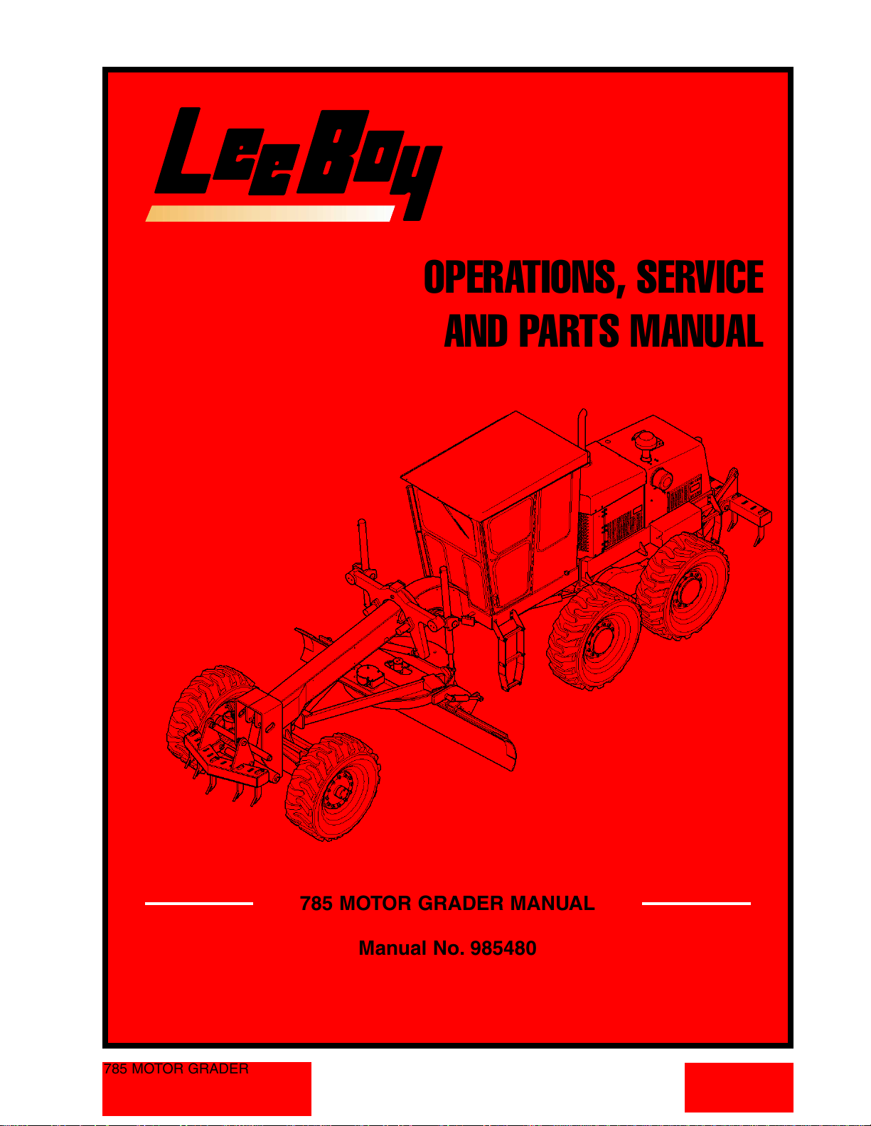
OPERATIONS, SERVICE
AND PARTS MANUAL
785 MOTOR GRADER
785 MOTOR GRADER MANUAL
Manual No. 985480
Courtesy of Machine.Market
Page 2

Courtesy of Machine.Market
Page 3
LIMITED WARRANTY
POLICY AND PROCEDURES
688 North Highway 16
Denver, North Carolina 28037
www.LeeBoy.com
WARRANTY
1. If a defect in material or workmanship is
found and the authorized dealer is notified
during the warranty period, LeeBoy will
repair or replace any part or component of
the unit or part that fails to conform to the
warranty during the warranty period.
2. The warranty date will begin upon the
completion of the warranty form by the initial
customer and will expire after twelve (12)
months have passed. The Warranty Card
should be filled out within (10) days of
delivery of the unit.
3. Engines are warranted by their
manufacturers and may have warranty
coverage that differs from that of LeeBoy.
4. Replacement parts furnished by LeeBoy are
covered for the remainder of the warranty
period applicable to the unit or component in
which such parts are installed.
5. LeeBoy has the right to repair any
component or part before replacing it with a
new part.
6. All new replacement parts purchased by a
LeeBoy dealer will carry a six (6) month
warranty. Remanufactured parts purchased
by a LeeBoy dealer will carry a ninety (90)
day warranty.
ITEMS NOT COVERED
LeeBoy is not responsible for the following:
1. Charges for travel time, mileage, or
overtime.
2. Charges related to transporting the product
to and from the place at which warranty
work is performed.
3. Airfreight charges related to transporting
repair parts to the place at which warranty
work is performed.
4. All used units or used parts of any kind.
5. Repairs due to normal wear and tear, or
brought about by abuse or lack of
maintenance of the equipment, except for
premature failures, conveyor chains,
polytrack pads, and track rails.
6. Attachments not manufactured or installed by
LeeBoy.
7. Liability for incidental or consequential
damages of any type including, but not
limited to lost profits or expenses of acquiring
replacement equipment.
8. Miscellaneous charges.
LIMITATIONS
LeeBoy has no obligation under this warranty for:
1. Any defects caused by misuse,
misapplication, negligence, accident or failure
to maintain or use in accordance with the
most current operating instructions.
2. Unauthorized alterations.
3. Defects or failures caused by any
replacement parts or attachments not
manufactured by or approved by LeeBoy.
4. Failure to conduct normal maintenance and
operating service, including without limitation,
providing lubricants, coolant, fuel, tune-ups,
inspections or adjustments.
5. Unreasonable delay, as established by
LeeBoy, in making the applicable units or
parts available upon notification of a service
notice ordered by LeeBoy.
6. The warranty responsibility on all engines
rests with the respective manufacturer.
7. LeeBoy may have support agreements with
some engine manufacturers for warranty and
parts support.
OTHER WARRANTIES
THE FOREGOING WARRANTY IS EXCLUSIVE AND IN
LIEU OF ALL OTHER EXPRESSED STATUTORY AND
IMPLIED WARRANTIES APPLICABLE TO UNITS ENGINES,
OR PARTS WITHOUT LIMITATION, ALL IMPLIED
WARRANTIES OF MERCHANTABILITY OR FITNESS FOR
ANY PARTICULAR USE OR PURPOSE. IN NO EVENT,
WHETHER AS A RESULT OF BREACH OF CONTRACT OR
WARRANTY, OR ALLEGED NEGLIGENCE OR LIABILITY
WITHOUT FAULT, SHALL LEEBOY BE LIABLE FOR
SPECIAL, INCIDENTAL OR CONSEQUENTIAL DAMAGES,
INCLUDING WITHOUT LIMITATION, LOSS OF PROFIT OR
REVENUE, COST OF CAPITAL, COST OF SUBSTITUTED
EQUIPMENT, FACILITIES OR SERVICES DOWNTIME
COSTS, LABOR COSTS OR CLAIMS OF CUSTOMERS,
PURCHASERS OR LESSEES FOR SUCH DAMAGES.
785 MOTOR GRADER
Courtesy of Machine.Market
Page 4
785 MOTOR GRADER
USER'S REFERENCE GUIDE
DELIVERY DATE______________________________________
UNIT SERIAL NUMBER_________________________________
ENGINE TYPE________________________________________
ENGINE NUMBER_____________________________________
DEALER'S NAME AND ADDRESS
_____________________________________________________
_____________________________________________________
PHONE NUMBER_______________________________________
EQUIPMENT HOURS____________________________________
SERVICE MANAGER ____________________________________
688 North Highway 16 • Denver, North Carolina 28037 • www.LeeBoy.com • (704) 966-3300
785 MOTOR GRADER
Courtesy of Machine.Market
Page 5
785 MOTOR GRADER
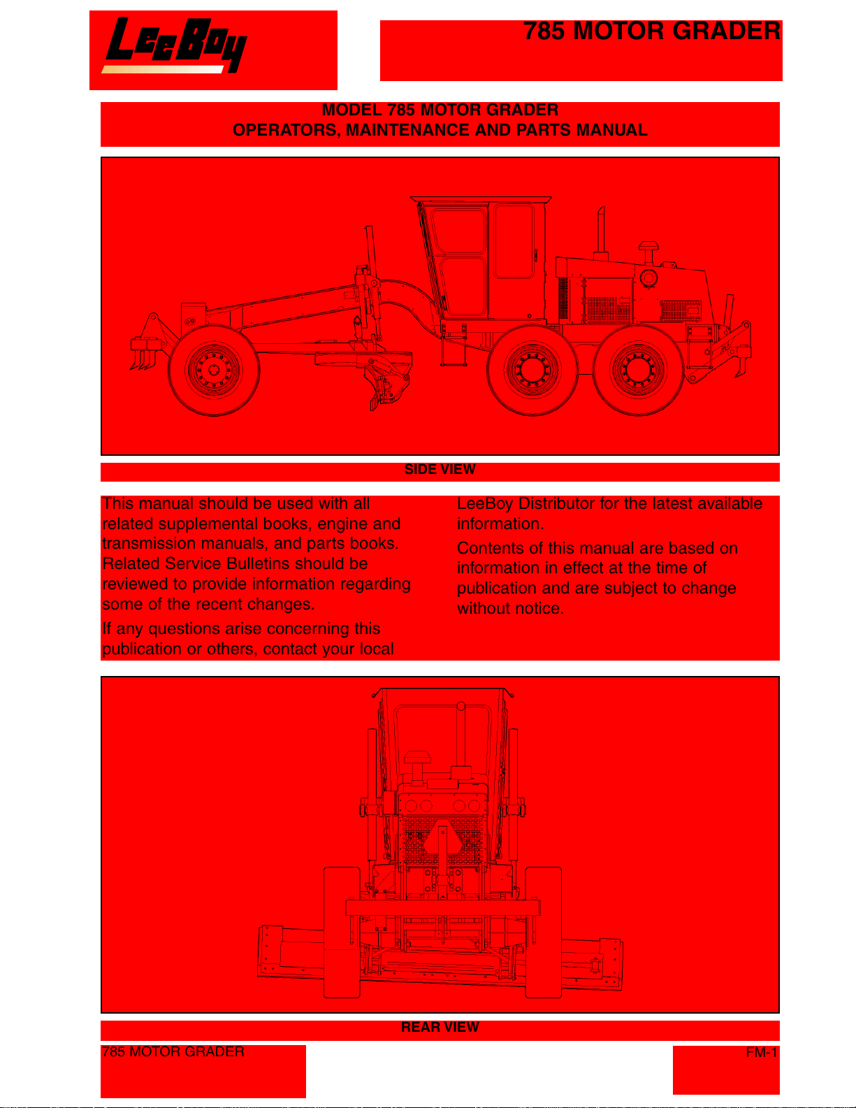
MODEL 785 MOTOR GRADER
OPERATORS, MAINTENANCE AND PARTS MANUAL
This manual should be used with all
related supplemental books, engine and
transmission manuals, and parts books.
Related Service Bulletins should be
reviewed to provide information regarding
some of the recent changes.
If any questions arise concerning this
publication or others, contact your local
SIDE VIEW
LeeBoy Distributor for the latest available
information.
Contents of this manual are based on
information in effect at the time of
publication and are subject to change
without notice.
785 MOTOR GRADER
REAR VIEW
FM-1
Courtesy of Machine.Market
Page 6
785 MOTOR GRADER
SAFETY INSTRUCTIONS
IIMMPPOORRTTAANNTT
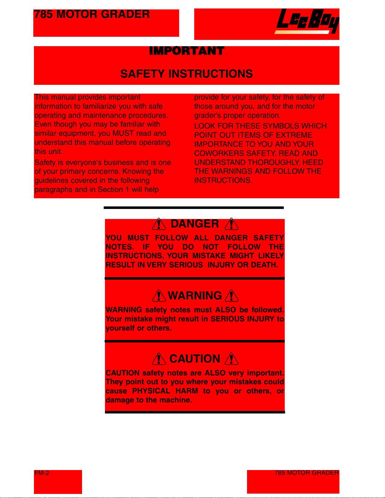
This manual provides important
information to familiarize you with safe
operating and maintenance procedures.
Even though you may be familiar with
similar equipment, you MUST read and
understand this manual before operating
this unit.
Safety is everyone's business and is one
of your primary concerns. Knowing the
guidelines covered in the following
paragraphs and in Section 1 will help
YOU MUST FOLLOW ALL DANGER SAFETY
NOTES. IF YOU DO NOT FOLLOW THE
INSTRUCTIONS, YOUR MISTAKE MIGHT LIKELY
RESULT IN VERY SERIOUS INJURY OR DEATH.
provide for your safety, for the safety of
those around you, and for the motor
grader's proper operation.
LOOK FOR THESE SYMBOLS WHICH
POINT OUT ITEMS OF EXTREME
IMPORTANCE TO YOU AND YOUR
COWORKERS SAFETY. READ AND
UNDERSTAND THOROUGHLY. HEED
THE WARNINGS AND FOLLOW THE
INSTRUCTIONS.
DANGER
FM-2
WARNING
WARNING safety notes must ALSO be followed.
Your mistake might result in SERIOUS INJURY to
yourself or others.
CAUTION
CAUTION safety notes are ALSO very important.
They point out to you where your mistakes could
cause PHYSICAL HARM to you or others, or
damage to the machine.
785 MOTOR GRADER
Courtesy of Machine.Market
Page 7
785 MOTOR GRADER
SAFETY PRECAUTIONS
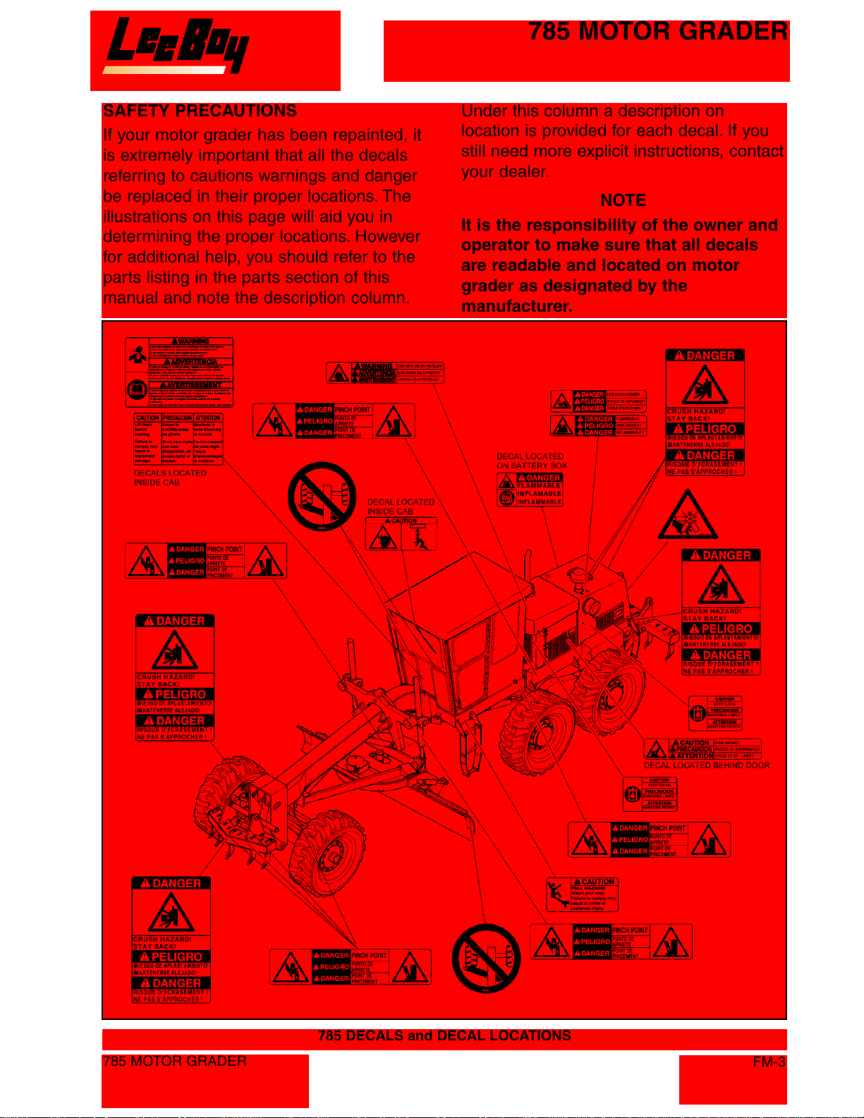
If your motor grader has been repainted, it
is extremely important that all the decals
referring to cautions warnings and danger
be replaced in their proper locations. The
illustrations on this page will aid you in
determining the proper locations. However
for additional help, you should refer to the
parts listing in the parts section of this
manual and note the description column.
Under this column a description on
location is provided for each decal. If you
still need more explicit instructions, contact
your dealer.
NOTE
It is the responsibility of the owner and
operator to make sure that all decals
are readable and located on motor
grader as designated by the
manufacturer.
785 MOTOR GRADER
785 DECALS and DECAL LOCATIONS
FM-3
Courtesy of Machine.Market
Page 8
785 MOTOR GRADER
PRE-START INSPECTION
INSPECT machine. Have any malfunctioning,
broken or missing parts corrected or replaced
before using. Hydraulic hoses should be checked
daily for wear and leaks. Replace if damaged.
CHECK that all the instruction and safety labels are
in place and readable. These are as important as
any other equipment on the machine.
READ and FOLLOW all instruction decals.
WEAR OSHA required safety equipment when
running the motor grader.
FILL the fuel tank with the engine off. Never fill fuel
tank near an open flame, when smoking.
Make sure all covers and guards are in place.
OPERATING SAFETY
ALWAYS make sure no person or object is in your
line of travel BEFORE starting.
WORK slowly in tight areas.
DO NOT run engine in a closed building for long
periods of time.
AVOID steep hills if possible.
ALWAYS look BEFORE changing your direction of
travel.
AVOID leaving engine running without operator
present.
ALWAYS wear your seatbelt.
NEVER attempt to jump clear of a tipping machine.
FATAL crushing injuries will result.
BEFORE moving machine, check that all persons
are clear.
When a signal person is used, BE SURE the
person is in view at all times.
To prevent rollaway accidents, MAKE SURE
machine is properly secured before leaving
operator's seat.
NEVER attempt to mount or stop a moving
machine.
USE handholds and steps when getting on or off
machine. Be CAREFUL of slippery conditions.
STOPPING SAFETY
ALWAYS park the motor grader on solid, level
ground in low range. If this is not possible, always
park the motor grader at a right angle to the slope.
USE proper flags, barriers and warning devices
especially when parking in areas of traffic.
DRIVING SAFETY
Know location of all bystanders before moving
machine.
BE SURE backup warning system is properly
operating.
USE a signal person when moving the machine.
AVOID power line, serious injury or death may
result.
KEEP riders off the machine.
MAINTENANCE SAFETY
NEVER work on the motor grader with the engine
running.
NEVER fill the fuel tank with the engine running.
DO NOT change the engine governor settings.
ALWAYS replace damaged or lost decals.
DISCONNECT battery cables when working on the
electrical system or when welding on the unit.
IF battery needs a charge, be sure battery charger
is off when making connections.
BE SURE the correct battery polarity is observed
(negative (-) to negative (-) and positive (+) to
positive (+), when connecting a battery charger or
jumper cable.
CLEAN trash from machine. Keep engine
compartment and operator's station clean.
WARN others of Service Work. Before performing
any machine work attach a "DO NOT OPERATE"
tag to steering wheel.
UNDERSTAND the service procedure before
beginning work.
ALWAYS lower attachments and implements to the
ground before servicing. If work is required on a
lifted machine or attachment, properly SUPPORT
machine attachment or implement before working
on it.
FM-4
785 MOTOR GRADER
Courtesy of Machine.Market
Page 9
Section 1
INTRODUCTION
TABLE OF CONTENTS
Page
GENERAL INFORMATION . . . . . . . . . . . . . . . . . . . . . . . . . . . . . . . . . . . . . . . . . . . . . . . . . . . . . . . .1-2
SPECIFICATIONS . . . . . . . . . . . . . . . . . . . . . . . . . . . . . . . . . . . . . . . . . . . . . . . . . . . . . . . . . . . . . .1-2
CONTROLS AND OPERATING INSTRUCTIONS . . . . . . . . . . . . . . . . . . . . . . . . . . . . . . . . . . . . . . .1-2
MAINTENANCE PROCEDURES . . . . . . . . . . . . . . . . . . . . . . . . . . . . . . . . . . . . . . . . . . . . . . . . . . .1-2
NAMEPLATE . . . . . . . . . . . . . . . . . . . . . . . . . . . . . . . . . . . . . . . . . . . . . . . . . . . . . . . . . . . . . . . . . .1-2
8500 Conveyor Paver
1-1
Courtesy of Machine.Market
Page 10
Section 1
INTRODUCTION
GENERAL INFORMATION
This manual contains Specification information,
Controls and Operating Procedures, Maintenance
and Repair Procedures and Parts Lists for the 785
Motor Grader.
SPECIFICATIONS
Refer to Section 2 - SPECIFICATIONS in this
manual for all major system specifications and for
typical torque value tables.
CONTROLS AND OPERATING
INSTRUCTIONS
Refer to Section 3 - OPERATION.
The operator of this equipment should READ,
UNDERSTAND, and FOLLOW the operating
instructions, Cautions, and Warnings provided in
the front of this manual and in the OPERATION
section.
WARNING: Do not attempt to operate the 785
Motor Grader unless fully trained
in the machine operation, only
authorized personnel should oper-
ate the Model 785 Motor Grader. All
instructions provided in this manu-
al and on the machine operating
and warning decals must be fol-
lowed to prevent damage to the
equipment and/or injury to operat-
ing personnel.
MAINTENANCE PROCEDURES
Refer to Section 4 - MAINTENANCE in this manual
for all maintenance and repair procedures.
CAUTION: All maintenance instructions
provided in this manual should be
followed to insure safety of the
personnel performing the
maintenance and to prevent
damage to the machine.
NAMEPLATE
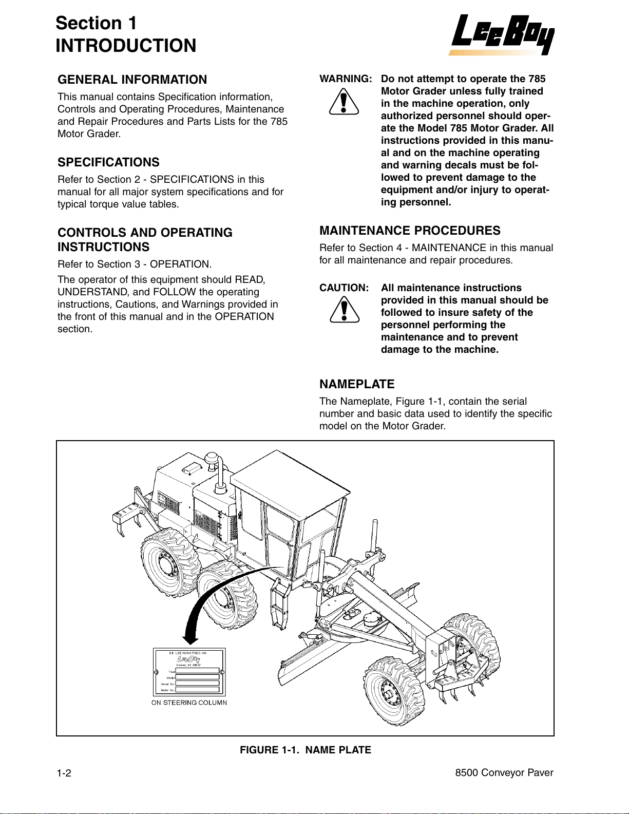
The Nameplate, Figure 1-1, contain the serial
number and basic data used to identify the specific
model on the Motor Grader.
1-2
FIGURE 1-1. NAME PLATE
8500 Conveyor Paver
Courtesy of Machine.Market
Page 11
Section 2
SPECIFICATIONS
TABLE OF CONTENTS
Page
GENERAL INFORMATION . . . . . . . . . . . . . . . . . . . . . . . . . . . . . . . . . . . . . . . . . . . . . . . . . . . . . . . 2-2
TABLE 2-1. ENGINE SPECIFICATIONS . . . . . . . . . . . . . . . . . . . . . . . . . . . . . . . . . . . . . . . . . . . . . 2-2
TABLE 2-2. ELECTRICAL SPECIFICATIONS. . . . . . . . . . . . . . . . . . . . . . . . . . . . . . . . . . . . . . . . . . 2-2
TABLE 2-3. DIMENSION SPECIFICATIONS . . . . . . . . . . . . . . . . . . . . . . . . . . . . . . . . . . . . . . . . . . 2-3
TABLE 2-4. PERFORMANCE SPECIFICATIONS. . . . . . . . . . . . . . . . . . . . . . . . . . . . . . . . . . . . . . . 2-3
TABLE 2-5. SCARIFIER. . . . . . . . . . . . . . . . . . . . . . . . . . . . . . . . . . . . . . . . . . . . . . . . . . . . . . . . . . 2-4
TABLE 2-6. MACHINE SYSTEM CAPACITY SPECIFICATIONS. . . . . . . . . . . . . . . . . . . . . . . . . . . . 2-4
TABLE 2-7. MOLDBOARD . . . . . . . . . . . . . . . . . . . . . . . . . . . . . . . . . . . . . . . . . . . . . . . . . . . . . . . .2-4
TABLE 2-8. HYDRAULIC SYSTEM . . . . . . . . . . . . . . . . . . . . . . . . . . . . . . . . . . . . . . . . . . . . . . . . . .2-4
TABLE 2-9 TRANSMISSION . . . . . . . . . . . . . . . . . . . . . . . . . . . . . . . . . . . . . . . . . . . . . . . . . . . . . .2-5
TABLE 2-10. TYPES OF LUBRICANTS . . . . . . . . . . . . . . . . . . . . . . . . . . . . . . . . . . . . . . . . . . . . . .2-5
TABLE 2-11. TIRES . . . . . . . . . . . . . . . . . . . . . . . . . . . . . . . . . . . . . . . . . . . . . . . . . . . . . . . . . . . . .2-5
TABLE 2-12. TORQUE SPECIFICATIONS FOR STANDARD INCH FASTENERS . . . . . . . . . . . . . . .2-6
TABLE 2-13. TORQUE SPECIFICATIONS FOR METRIC FASTENERS . . . . . . . . . . . . . . . . . . . . . .2-7
785 Motor Grader
2-1
Courtesy of Machine.Market
Page 12
Section 2
SPECIFICATIONS
GENERAL INFORMATION
The specifications provided in this section are applicable to the Model 785 Motor Grader. Included in this section
are machine weights, dimensions, performance and torque values for both metric and standard inch fasteners.
TABLE 2-1. ENGINE SPECIFICATIONS
ITEM CHARACTERISTIC
ENGINE
Manufacturer . . . . . . . . . . . . . . . . . . . . . .Cummins 3.9L
Horsepower . . . . . . . . . . . . . . . . . . . . . . .130 HP @2500 rpm
Type . . . . . . . . . . . . . . . . . . . . . . . . . . . .Four Stroke Turbo Charged and Charge Air
Cooled, In-Line 4 cylinder Diesel engine
(Tier II Compliant)
Bore & Stroke . . . . . . . . . . . . . . . . . . . . .4.02 in. [102 mm] x 4.72 in. [120 mm]
Displacement . . . . . . . . . . . . . . . . . . . . .238 cu. In.
Compression Ratio . . . . . . . . . . . . . . . . .18:01
Maximum Net Torque . . . . . . . . . . . . . . .355 Pound/Foot @1500 rpm
Lubrication system . . . . . . . . . . . . . . . . .Pressure System With Full Flow Filter
Air Cleaner . . . . . . . . . . . . . . . . . . . . . . .Two Stage Dry Element
Engine Oil Type . . . . . . . . . . . . . . . . . . .10W-40
Capacity . . . . . . . . . . . . . . . . . . . . . . . . .10 Quarts [9.46 liter]
ENGINE COOLING SYSTEM
Type . . . . . . . . . . . . . . . . . . . . . . . . . . . .Liquid,
ENGINE FUEL
Type Used . . . . . . . . . . . . . . . . . . . . . . . .Diesel Fuel
Fuel Capacity . . . . . . . . . . . . . . . . . . . . .50 gallons [189.3 liters]
FUEL FILTER
Spin-On . . . . . . . . . . . . . . . . . . . . . . . . .Cummins P/N 3991498/Fleetguard FS19616
In-Line . . . . . . . . . . . . . . . . . . . . . . . . . .P/N 981937
2-2
TABLE 2-2. ELECTRICAL SPECIFICATIONS
ITEM CHARACTERISTIC
BATTERY
Number Per Machine . . . . . . . . . . . . . . . .Two maintenance free
Ampere Hour Rating . . . . . . . . . . . . . . . .950 CCA
Voltage . . . . . . . . . . . . . . . . . . . . . . . . . .12 Volts
ALTERNATOR
Voltage . . . . . . . . . . . . . . . . . . . . . . . . . .12 Volt, negative ground
Output Amperage . . . . . . . . . . . . . . . . . .100 Amps
Fan Belt Tension . . . . . . . . . . . . . . . . . . .Belt tension mechanism keeps serpentine
belt under tension at all times
STARTER
Manufacturer . . . . . . . . . . . . . . . . . . . . . .(See Engine Starter plate)
Voltage and Type . . . . . . . . . . . . . . . . . . .12 Volt, negative ground
785 Motor Grader
Courtesy of Machine.Market
Page 13
SPECIFICATIONS
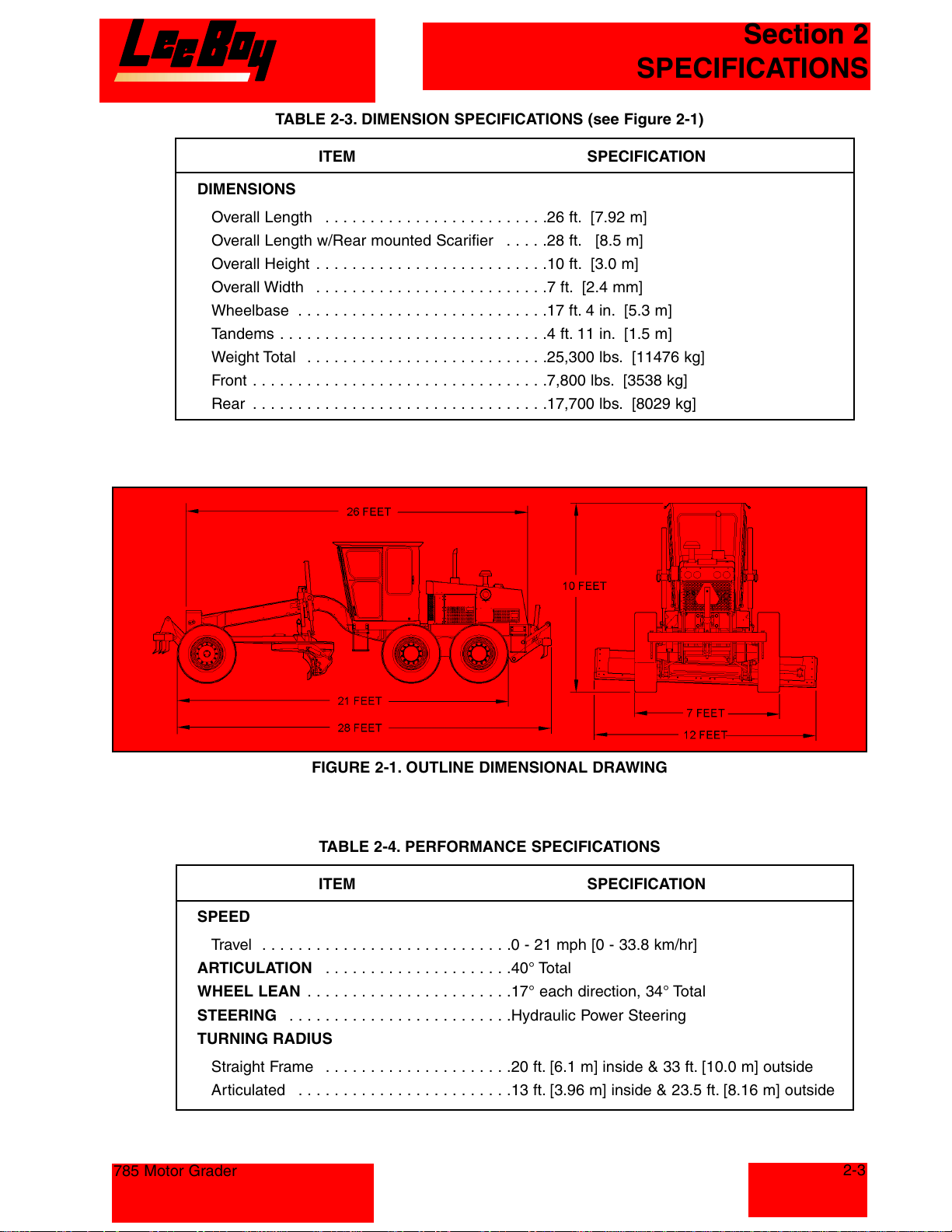
TABLE 2-3. DIMENSION SPECIFICATIONS (see Figure 2-1)
ITEM SPECIFICATION
DIMENSIONS
Overall Length . . . . . . . . . . . . . . . . . . . . . . . . .26 ft. [7.92 m]
Overall Length w/Rear mounted Scarifier . . . . .28 ft. [8.5 m]
Overall Height . . . . . . . . . . . . . . . . . . . . . . . . . .10 ft. [3.0 m]
Overall Width . . . . . . . . . . . . . . . . . . . . . . . . . .7 ft. [2.4 mm]
Wheelbase . . . . . . . . . . . . . . . . . . . . . . . . . . . .17 ft. 4 in. [5.3 m]
Tandems . . . . . . . . . . . . . . . . . . . . . . . . . . . . . .4 ft. 11 in. [1.5 m]
Weight Total . . . . . . . . . . . . . . . . . . . . . . . . . . .25,300 lbs. [11476 kg]
Front . . . . . . . . . . . . . . . . . . . . . . . . . . . . . . . . .7,800 lbs. [3538 kg]
Rear . . . . . . . . . . . . . . . . . . . . . . . . . . . . . . . . .17,700 lbs. [8029 kg]
Section 2
SPEED
Travel . . . . . . . . . . . . . . . . . . . . . . . . . . . .0 - 21 mph [0 - 33.8 km/hr]
ARTICULATION . . . . . . . . . . . . . . . . . . . . .40° Total
WHEEL LEAN . . . . . . . . . . . . . . . . . . . . . . .17° each direction, 34° Total
STEERING . . . . . . . . . . . . . . . . . . . . . . . . .Hydraulic Power Steering
TURNING RADIUS
Straight Frame . . . . . . . . . . . . . . . . . . . . .20 ft. [6.1 m] inside & 33 ft. [10.0 m] outside
Articulated . . . . . . . . . . . . . . . . . . . . . . . .13 ft. [3.96 m] inside & 23.5 ft. [8.16 m] outside
785 Motor Grader
FIGURE 2-1. OUTLINE DIMENSIONAL DRAWING
TABLE 2-4. PERFORMANCE SPECIFICATIONS
ITEM SPECIFICATION
2-3
Courtesy of Machine.Market
Page 14
Section 2
SPECIFICATIONS
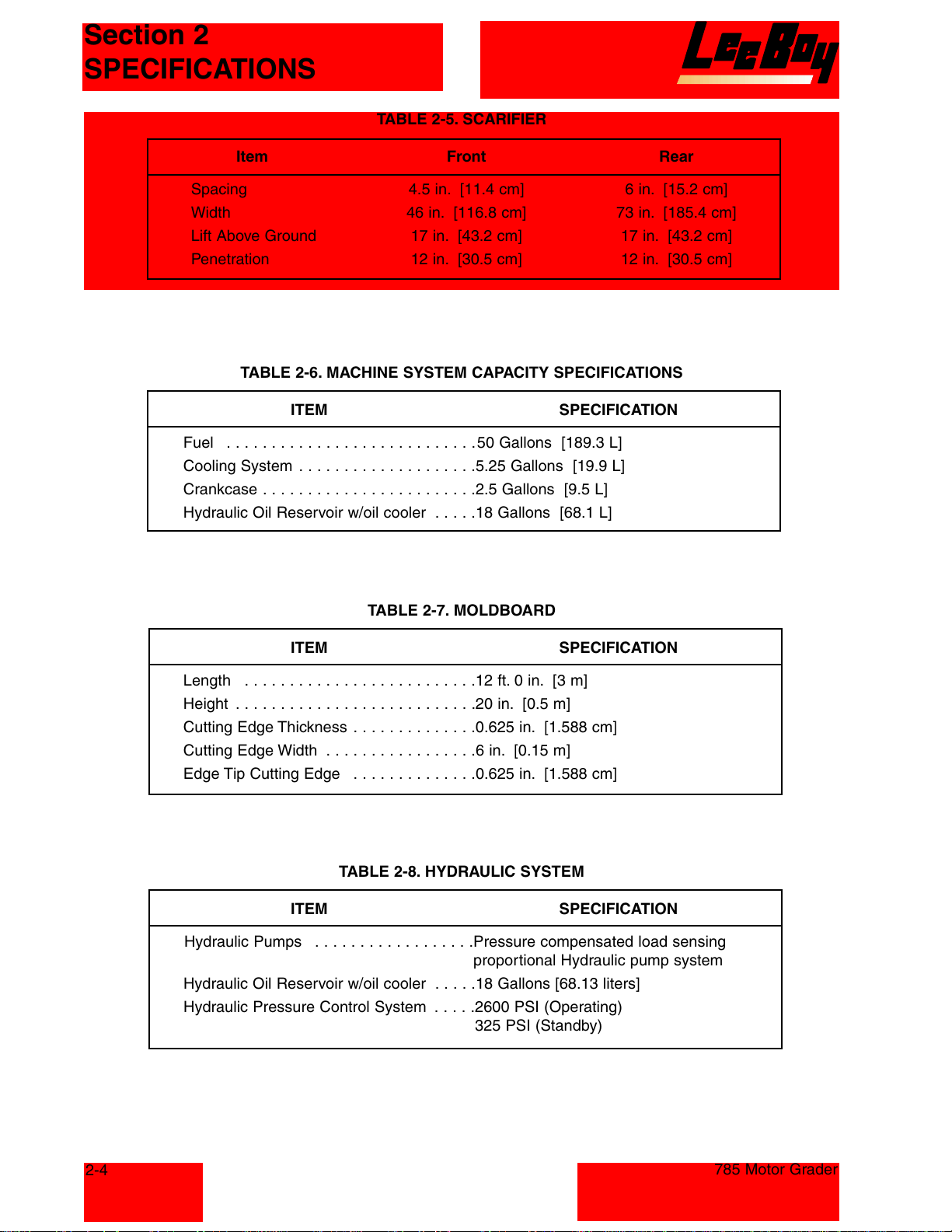
Item Front Rear
Spacing 4.5 in. [11.4 cm] 6 in. [15.2 cm]
Width 46 in. [116.8 cm] 73 in. [185.4 cm]
Lift Above Ground 17 in. [43.2 cm] 17 in. [43.2 cm]
Penetration 12 in. [30.5 cm] 12 in. [30.5 cm]
TABLE 2-6. MACHINE SYSTEM CAPACITY SPECIFICATIONS
ITEM SPECIFICATION
Fuel . . . . . . . . . . . . . . . . . . . . . . . . . . . .50 Gallons [189.3 L]
Cooling System . . . . . . . . . . . . . . . . . . . .5.25 Gallons [19.9 L]
Crankcase . . . . . . . . . . . . . . . . . . . . . . . .2.5 Gallons [9.5 L]
Hydraulic Oil Reservoir w/oil cooler . . . . .18 Gallons [68.1 L]
TABLE 2-5. SCARIFIER
TABLE 2-7. MOLDBOARD
ITEM SPECIFICATION
Length . . . . . . . . . . . . . . . . . . . . . . . . . .12 ft. 0 in. [3 m]
Height . . . . . . . . . . . . . . . . . . . . . . . . . . .20 in. [0.5 m]
Cutting Edge Thickness . . . . . . . . . . . . . .0.625 in. [1.588 cm]
Cutting Edge Width . . . . . . . . . . . . . . . . .6 in. [0.15 m]
Edge Tip Cutting Edge . . . . . . . . . . . . . .0.625 in. [1.588 cm]
TABLE 2-8. HYDRAULIC SYSTEM
ITEM SPECIFICATION
Hydraulic Pumps . . . . . . . . . . . . . . . . . .Pressure compensated load sensing
proportional Hydraulic pump system
Hydraulic Oil Reservoir w/oil cooler . . . . .18 Gallons [68.13 liters]
Hydraulic Pressure Control System . . . . .2600 PSI (Operating)
325 PSI (Standby)
2-4
785 Motor Grader
Courtesy of Machine.Market
Page 15
Section 2
SPECIFICATIONS
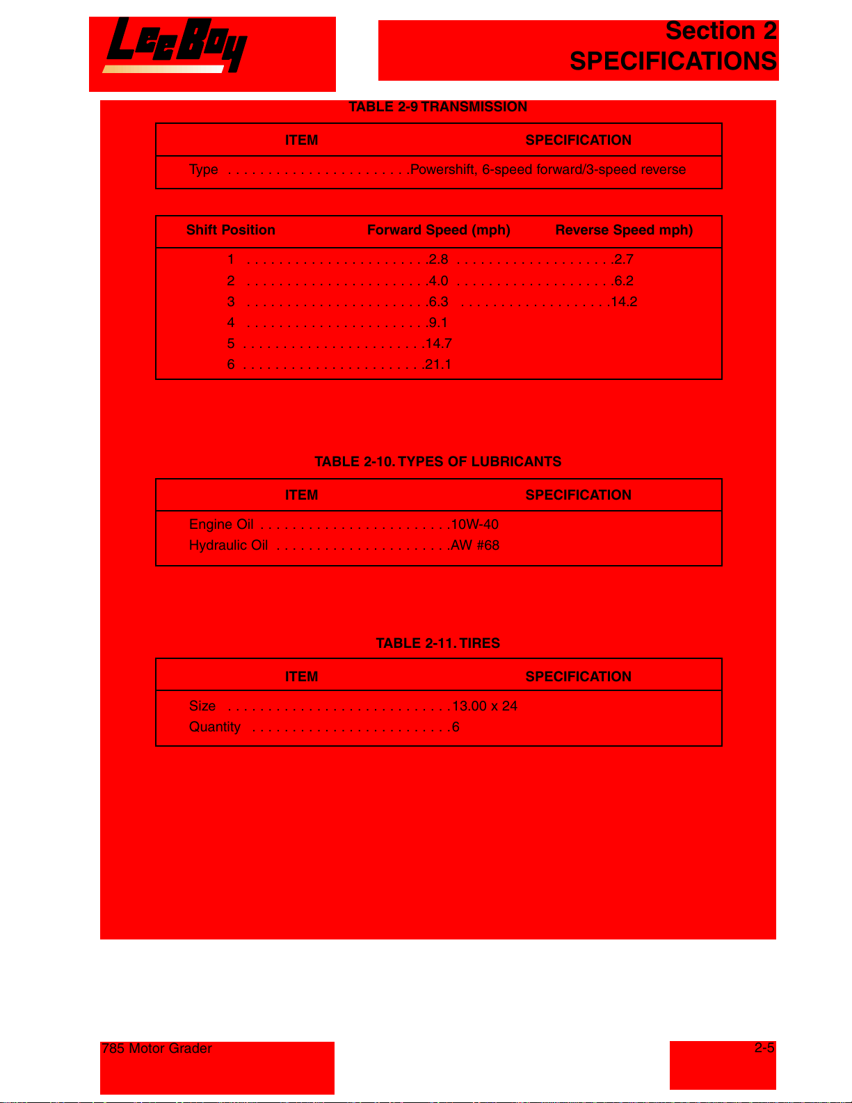
TABLE 2-9 TRANSMISSION
ITEM SPECIFICATION
Type . . . . . . . . . . . . . . . . . . . . . . .Powershift, 6-speed forward/3-speed reverse
Shift Position Forward Speed (mph) Reverse Speed mph)
1 . . . . . . . . . . . . . . . . . . . . . . .2.8 . . . . . . . . . . . . . . . . . . . .2.7
2 . . . . . . . . . . . . . . . . . . . . . . .4.0 . . . . . . . . . . . . . . . . . . . .6.2
3 . . . . . . . . . . . . . . . . . . . . . . .6.3 . . . . . . . . . . . . . . . . . . .14.2
4 . . . . . . . . . . . . . . . . . . . . . . .9.1
5 . . . . . . . . . . . . . . . . . . . . . . .14.7
6 . . . . . . . . . . . . . . . . . . . . . . .21.1
TABLE 2-10. TYPES OF LUBRICANTS
ITEM SPECIFICATION
Engine Oil . . . . . . . . . . . . . . . . . . . . . . . .10W-40
Hydraulic Oil . . . . . . . . . . . . . . . . . . . . . .AW #68
TABLE 2-11. TIRES
ITEM SPECIFICATION
Size . . . . . . . . . . . . . . . . . . . . . . . . . . . .13.00 x 24
Quantity . . . . . . . . . . . . . . . . . . . . . . . . . 6
785 Motor Grader
2-5
Courtesy of Machine.Market
Page 16
Section 2
SPECIFICATIONS
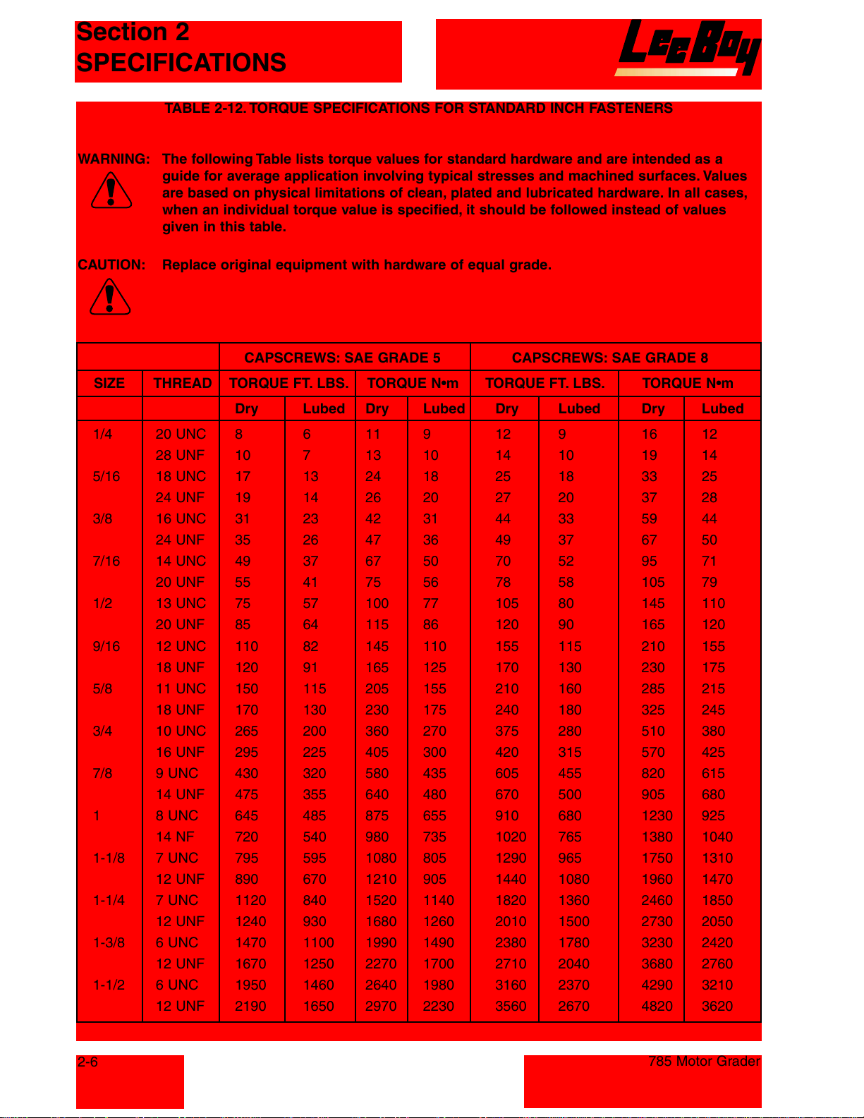
TABLE 2-12. TORQUE SPECIFICATIONS FOR STANDARD INCH FASTENERS
WARNING: The following Table lists torque values for standard hardware and are intended as a
guide for average application involving typical stresses and machined surfaces. Values
are based on physical limitations of clean, plated and lubricated hardware. In all cases,
when an individual torque value is specified, it should be followed instead of values
given in this table.
CAUTION: Replace original equipment with hardware of equal grade.
CAPSCREWS: SAE GRADE 5 CAPSCREWS: SAE GRADE 8
SIZE THREAD TORQUE FT. LBS. TORQUE N•m TORQUE FT. LBS. TORQUE N•m
Dry Lubed Dry Lubed Dry Lubed Dry Lubed
1/4 20 UNC 8 6 11 9 12 9 16 12
28 UNF 10 7 13 10 14 10 19 14
5/16 18 UNC 17 13 24 18 25 18 33 25
24 UNF 19 14 26 20 27 20 37 28
3/8 16 UNC 31 23 42 31 44 33 59 44
24 UNF 35 26 47 36 49 37 67 50
7/16 14 UNC 49 37 67 50 70 52 95 71
20 UNF 55 41 75 56 78 58 105 79
1/2 13 UNC 75 57 100 77 105 80 145 110
20 UNF 85 64 115 86 120 90 165 120
9/16 12 UNC 110 82 145 110 155 115 210 155
18 UNF 120 91 165 125 170 130 230 175
5/8 11 UNC 150 115 205 155 210 160 285 215
18 UNF 170 130 230 175 240 180 325 245
3/4 10 UNC 265 200 360 270 375 280 510 380
16 UNF 295 225 405 300 420 315 570 425
7/8 9 UNC 430 320 580 435 605 455 820 615
14 UNF 475 355 640 480 670 500 905 680
1 8 UNC 645 485 875 655 910 680 1230 925
14 NF 720 540 980 735 1020 765 1380 1040
1-1/8 7 UNC 795 595 1080 805 1290 965 1750 1310
12 UNF 890 670 1210 905 1440 1080 1960 1470
1-1/4 7 UNC 1120 840 1520 1140 1820 1360 2460 1850
12 UNF 1240 930 1680 1260 2010 1500 2730 2050
1-3/8 6 UNC 1470 1100 1990 1490 2380 1780 3230 2420
12 UNF 1670 1250 2270 1700 2710 2040 3680 2760
1-1/2 6 UNC 1950 1460 2640 1980 3160 2370 4290 3210
12 UNF 2190 1650 2970 2230 3560 2670 4820 3620
2-6
785 Motor Grader
Courtesy of Machine.Market
Page 17
Section 2
SPECIFICATIONS
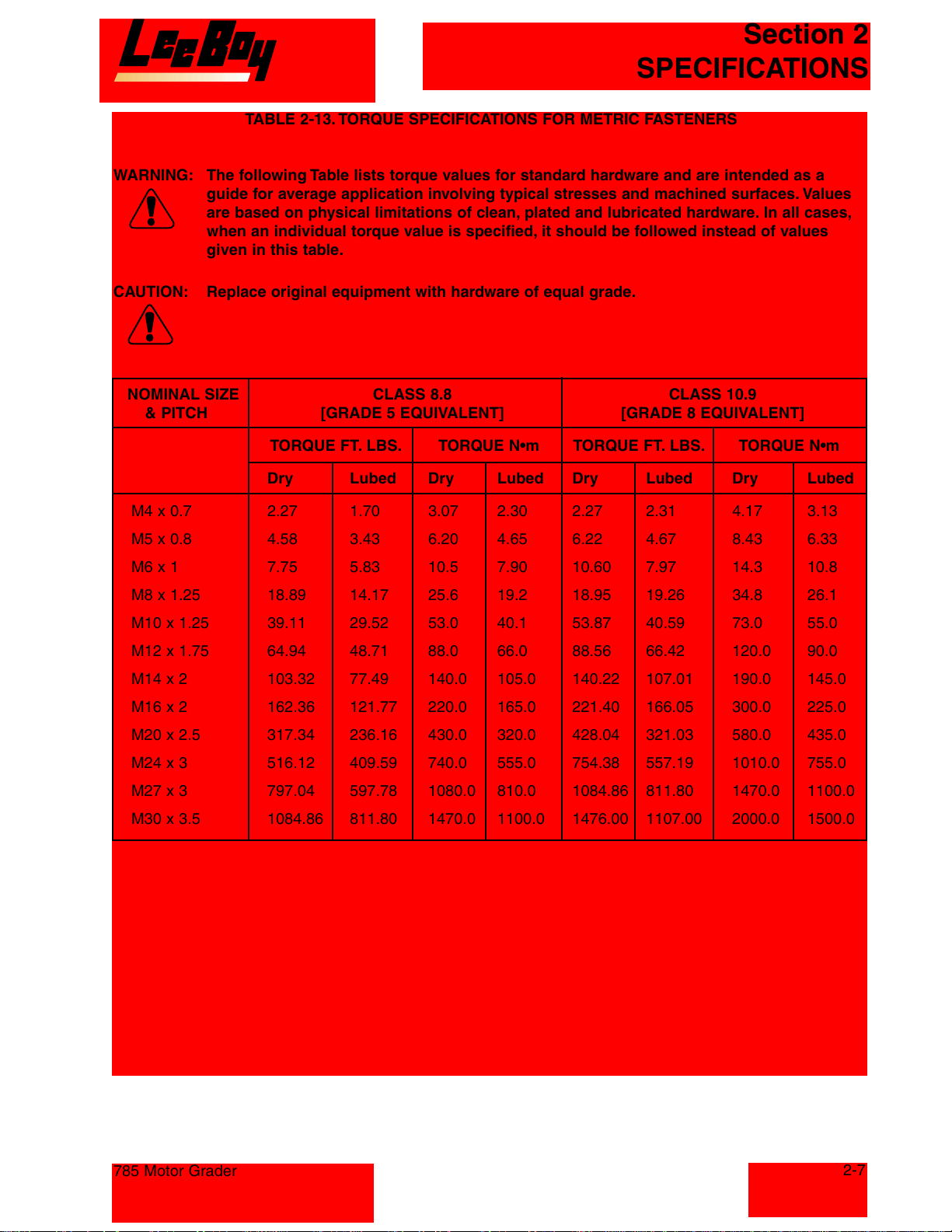
TABLE 2-13. TORQUE SPECIFICATIONS FOR METRIC FASTENERS
WARNING: The following Table lists torque values for standard hardware and are intended as a
guide for average application involving typical stresses and machined surfaces. Values
are based on physical limitations of clean, plated and lubricated hardware. In all cases,
when an individual torque value is specified, it should be followed instead of values
given in this table.
CAUTION: Replace original equipment with hardware of equal grade.
NOMINAL SIZE CLASS 8.8 CLASS 10.9
& PITCH [GRADE 5 EQUIVALENT] [GRADE 8 EQUIVALENT]
TORQUE FT. LBS. TORQUE N•m TORQUE FT. LBS. TORQUE N•m
Dry Lubed Dry Lubed Dry Lubed Dry Lubed
M4 x 0.7 2.27 1.70 3.07 2.30 2.27 2.31 4.17 3.13
M5 x 0.8 4.58 3.43 6.20 4.65 6.22 4.67 8.43 6.33
M6 x 1 7.75 5.83 10.5 7.90 10.60 7.97 14.3 10.8
M8 x 1.25 18.89 14.17 25.6 19.2 18.95 19.26 34.8 26.1
M10 x 1.25 39.11 29.52 53.0 40.1 53.87 40.59 73.0 55.0
M12 x 1.75 64.94 48.71 88.0 66.0 88.56 66.42 120.0 90.0
M14 x 2 103.32 77.49 140.0 105.0 140.22 107.01 190.0 145.0
M16 x 2 162.36 121.77 220.0 165.0 221.40 166.05 300.0 225.0
M20 x 2.5 317.34 236.16 430.0 320.0 428.04 321.03 580.0 435.0
M24 x 3 516.12 409.59 740.0 555.0 754.38 557.19 1010.0 755.0
M27 x 3 797.04 597.78 1080.0 810.0 1084.86 811.80 1470.0 1100.0
M30 x 3.5 1084.86 811.80 1470.0 1100.0 1476.00 1107.00 2000.0 1500.0
785 Motor Grader
2-7
Courtesy of Machine.Market
Page 18

Section 2
SPECIFICATIONS
NOTES
2-8
785 Motor Grader
Courtesy of Machine.Market
Page 19
Section 3
OPERATION
TABLE OF CONTENTS
Page
GENERAL INFORMATION . . . . . . . . . . . . . . . . . . . . . . . . . . . . . . . . . . . . . . . . . . . . . . . . . . . . . . . .3-3
OPERATING CONTROLS, INDICATORS, AND GAUGES . . . . . . . . . . . . . . . . . . . . . . . . . . . . . . . . .3-3
OPERATION . . . . . . . . . . . . . . . . . . . . . . . . . . . . . . . . . . . . . . . . . . . . . . . . . . . . . . . . . . . . . . . . .3-16
SAFETY . . . . . . . . . . . . . . . . . . . . . . . . . . . . . . . . . . . . . . . . . . . . . . . . . . . . . . . . . . . . . . . . . .3-16
Operating Safety . . . . . . . . . . . . . . . . . . . . . . . . . . . . . . . . . . . . . . . . . . . . . . . . . . . . . . . . . . .3-16
Stopping Safety . . . . . . . . . . . . . . . . . . . . . . . . . . . . . . . . . . . . . . . . . . . . . . . . . . . . . . . . . . .3-16
Maintenance Safety . . . . . . . . . . . . . . . . . . . . . . . . . . . . . . . . . . . . . . . . . . . . . . . . . . . . . . . .3-16
INSPECTION . . . . . . . . . . . . . . . . . . . . . . . . . . . . . . . . . . . . . . . . . . . . . . . . . . . . . . . . . . . . . . .3-17
Introduction . . . . . . . . . . . . . . . . . . . . . . . . . . . . . . . . . . . . . . . . . . . . . . . . . . . . . . . . . . . . . .3-17
Receiving Inspection . . . . . . . . . . . . . . . . . . . . . . . . . . . . . . . . . . . . . . . . . . . . . . . . . . . . . . .3-17
Inspection Before Initial Start-Up . . . . . . . . . . . . . . . . . . . . . . . . . . . . . . . . . . . . . . . . . . . . . .3-17
Preliminary Procedures . . . . . . . . . . . . . . . . . . . . . . . . . . . . . . . . . . . . . . . . . . . . . . . . . . . . .3-18
Adjusting Front Console . . . . . . . . . . . . . . . . . . . . . . . . . . . . . . . . . . . . . . . . . . . . . . . . . . .3-18
Air Conditioner . . . . . . . . . . . . . . . . . . . . . . . . . . . . . . . . . . . . . . . . . . . . . . . . . . . . . . . . . .3-18
Defroster Fan . . . . . . . . . . . . . . . . . . . . . . . . . . . . . . . . . . . . . . . . . . . . . . . . . . . . . . . . . . .3-18
Opening Windshield . . . . . . . . . . . . . . . . . . . . . . . . . . . . . . . . . . . . . . . . . . . . . . . . . . . . . .3-18
Cab Door Release Levers . . . . . . . . . . . . . . . . . . . . . . . . . . . . . . . . . . . . . . . . . . . . . . . . . .3-18
Cab Light . . . . . . . . . . . . . . . . . . . . . . . . . . . . . . . . . . . . . . . . . . . . . . . . . . . . . . . . . . . . . .3-18
Console Light . . . . . . . . . . . . . . . . . . . . . . . . . . . . . . . . . . . . . . . . . . . . . . . . . . . . . . . . . . .3-18
DRIVING THE MACHINE . . . . . . . . . . . . . . . . . . . . . . . . . . . . . . . . . . . . . . . . . . . . . . . . . . . . . .3-18
Startup Procedure . . . . . . . . . . . . . . . . . . . . . . . . . . . . . . . . . . . . . . . . . . . . . . . . . . . . . . . . .3-18
Using Booster Batteries . . . . . . . . . . . . . . . . . . . . . . . . . . . . . . . . . . . . . . . . . . . . . . . . . . . . .3-19
Engine Shutdown . . . . . . . . . . . . . . . . . . . . . . . . . . . . . . . . . . . . . . . . . . . . . . . . . . . . . . . . . .3-19
Auto Mode . . . . . . . . . . . . . . . . . . . . . . . . . . . . . . . . . . . . . . . . . . . . . . . . . . . . . . . . . . . . . . .3-19
Moving Forward/Reverse . . . . . . . . . . . . . . . . . . . . . . . . . . . . . . . . . . . . . . . . . . . . . . . . . .3-19
Stopping . . . . . . . . . . . . . . . . . . . . . . . . . . . . . . . . . . . . . . . . . . . . . . . . . . . . . . . . . . . . . . .3-19
Stopping and Restarting . . . . . . . . . . . . . . . . . . . . . . . . . . . . . . . . . . . . . . . . . . . . . . . . . . .3-20
Manual Mode . . . . . . . . . . . . . . . . . . . . . . . . . . . . . . . . . . . . . . . . . . . . . . . . . . . . . . . . . . . . .3-20
Moving Forward/Reverse . . . . . . . . . . . . . . . . . . . . . . . . . . . . . . . . . . . . . . . . . . . . . . . . . .3-20
Stopping . . . . . . . . . . . . . . . . . . . . . . . . . . . . . . . . . . . . . . . . . . . . . . . . . . . . . . . . . . . . . . .3-20
Stopping and Restarting . . . . . . . . . . . . . . . . . . . . . . . . . . . . . . . . . . . . . . . . . . . . . . . . . . .3-20
OPERATING THE MACHINE . . . . . . . . . . . . . . . . . . . . . . . . . . . . . . . . . . . . . . . . . . . . . . . . . . .3-20
Blade Lift Levers . . . . . . . . . . . . . . . . . . . . . . . . . . . . . . . . . . . . . . . . . . . . . . . . . . . . . . . . . . .3-20
Moldboard Slide Lever . . . . . . . . . . . . . . . . . . . . . . . . . . . . . . . . . . . . . . . . . . . . . . . . . . . . . .3-20
Blade Tilt Lever . . . . . . . . . . . . . . . . . . . . . . . . . . . . . . . . . . . . . . . . . . . . . . . . . . . . . . . . . . .3-20
785 Motor Grader
Courtesy of Machine.Market
3-1
Page 20
Section 3
OPERATION
Circle Turn Lever . . . . . . . . . . . . . . . . . . . . . . . . . . . . . . . . . . . . . . . . . . . . . . . . . . . . . . . . . .3-20
Circle Shift Lever . . . . . . . . . . . . . . . . . . . . . . . . . . . . . . . . . . . . . . . . . . . . . . . . . . . . . . . . . .3-20
Articulation Lever . . . . . . . . . . . . . . . . . . . . . . . . . . . . . . . . . . . . . . . . . . . . . . . . . . . . . . . . . .3-20
Leaning Wheel Lever . . . . . . . . . . . . . . . . . . . . . . . . . . . . . . . . . . . . . . . . . . . . . . . . . . . . . . .3-21
Scarifier Lever . . . . . . . . . . . . . . . . . . . . . . . . . . . . . . . . . . . . . . . . . . . . . . . . . . . . . . . . . . . .3-21
Differential Lock Switch . . . . . . . . . . . . . . . . . . . . . . . . . . . . . . . . . . . . . . . . . . . . . . . . . . . . .3-21
Moving Blade to Bank Position . . . . . . . . . . . . . . . . . . . . . . . . . . . . . . . . . . . . . . . . . . . . . . . .3-21
Steering . . . . . . . . . . . . . . . . . . . . . . . . . . . . . . . . . . . . . . . . . . . . . . . . . . . . . . . . . . . . . . . . .3-21
Blade Side Thrust . . . . . . . . . . . . . . . . . . . . . . . . . . . . . . . . . . . . . . . . . . . . . . . . . . . . . . . . . .3-21
Blade Pitch Adjustment . . . . . . . . . . . . . . . . . . . . . . . . . . . . . . . . . . . . . . . . . . . . . . . . . . . . .3-21
Pile Spreading . . . . . . . . . . . . . . . . . . . . . . . . . . . . . . . . . . . . . . . . . . . . . . . . . . . . . . . . . . . .3-21
TABLE OF CONTENTS (Continued)
Page
Back Filling . . . . . . . . . . . . . . . . . . . . . . . . . . . . . . . . . . . . . . . . . . . . . . . . . . . . . . . . . . . . . .3-22
Vee Ditching . . . . . . . . . . . . . . . . . . . . . . . . . . . . . . . . . . . . . . . . . . . . . . . . . . . . . . . . . . . . . .3-22
First Pass . . . . . . . . . . . . . . . . . . . . . . . . . . . . . . . . . . . . . . . . . . . . . . . . . . . . . . . . . . . . . .3-22
Second Pass . . . . . . . . . . . . . . . . . . . . . . . . . . . . . . . . . . . . . . . . . . . . . . . . . . . . . . . . . . . .3-22
Third Pass . . . . . . . . . . . . . . . . . . . . . . . . . . . . . . . . . . . . . . . . . . . . . . . . . . . . . . . . . . . . . .3-22
Spreading Material . . . . . . . . . . . . . . . . . . . . . . . . . . . . . . . . . . . . . . . . . . . . . . . . . . . . . . . . .3-22
Cutting Back Slope . . . . . . . . . . . . . . . . . . . . . . . . . . . . . . . . . . . . . . . . . . . . . . . . . . . . . . . . .3-22
Cleaning Ditches . . . . . . . . . . . . . . . . . . . . . . . . . . . . . . . . . . . . . . . . . . . . . . . . . . . . . . . . . .3-22
Road Crowning . . . . . . . . . . . . . . . . . . . . . . . . . . . . . . . . . . . . . . . . . . . . . . . . . . . . . . . . . . .3-22
Bank Cutting . . . . . . . . . . . . . . . . . . . . . . . . . . . . . . . . . . . . . . . . . . . . . . . . . . . . . . . . . . . . .3-23
Slope Work . . . . . . . . . . . . . . . . . . . . . . . . . . . . . . . . . . . . . . . . . . . . . . . . . . . . . . . . . . . . . .3-23
Cul De Sacs . . . . . . . . . . . . . . . . . . . . . . . . . . . . . . . . . . . . . . . . . . . . . . . . . . . . . . . . . . . . . .3-23
LOADING THE GRADER ON A TRAILER . . . . . . . . . . . . . . . . . . . . . . . . . . . . . . . . . . . . . . . .3-23
TOWING PROCEDURE . . . . . . . . . . . . . . . . . . . . . . . . . . . . . . . . . . . . . . . . . . . . . . . . . . . . . .3-24
3-2 785 Motor Grader
Courtesy of Machine.Market
Page 21
Section 3
OPERATION
GENERAL INFORMATION
This section provides the Operating Instructions for
the Model 785 Motor Grader.
It is important to read, understand, and follow all
"Precautions, Operating Instructions and Warnings"
written in this manual before starting or operating
the machine.
DANGER: Failure to observe the “Precautions,
Operating Instructions and
Warnings” provided in this manual
can cause serious injury or death.
Only authorized personnel, who are
fully trained in the machine opera-
tion, can operate the Model 785
Motor Grader.
This machine should be kept in good mechanical
condition at all times.
WARNING: Do not operate a machine needing
repair. Put an information tag on
the instrument panel that says,
“DO NOT OPERATE”. Remove the
key from the ignition switch.
Repair all damage at once. Minor
damage can result in major system
failures.
OPERATING CONTROLS, INDICATORS,
AND GAUGES
Operating controls for the Model 785 Motor Grader
are shown in Figures 3-1 through 3-6 and listed in
Tables 3-1 through 3-6.
WARNING: Do not start or operate the Model
785 Motor Grader before reading,
understanding and following all
information given in this section
and shown on the machine. The
operators must read and under-
stand the function of all controls,
indicators, and gauges before
starting the engine. Serious injury
or death can result if these proce-
dures are not followed.
785 Motor Grader
3-3
Courtesy of Machine.Market
Page 22
Section 3
OPERATION
3-4
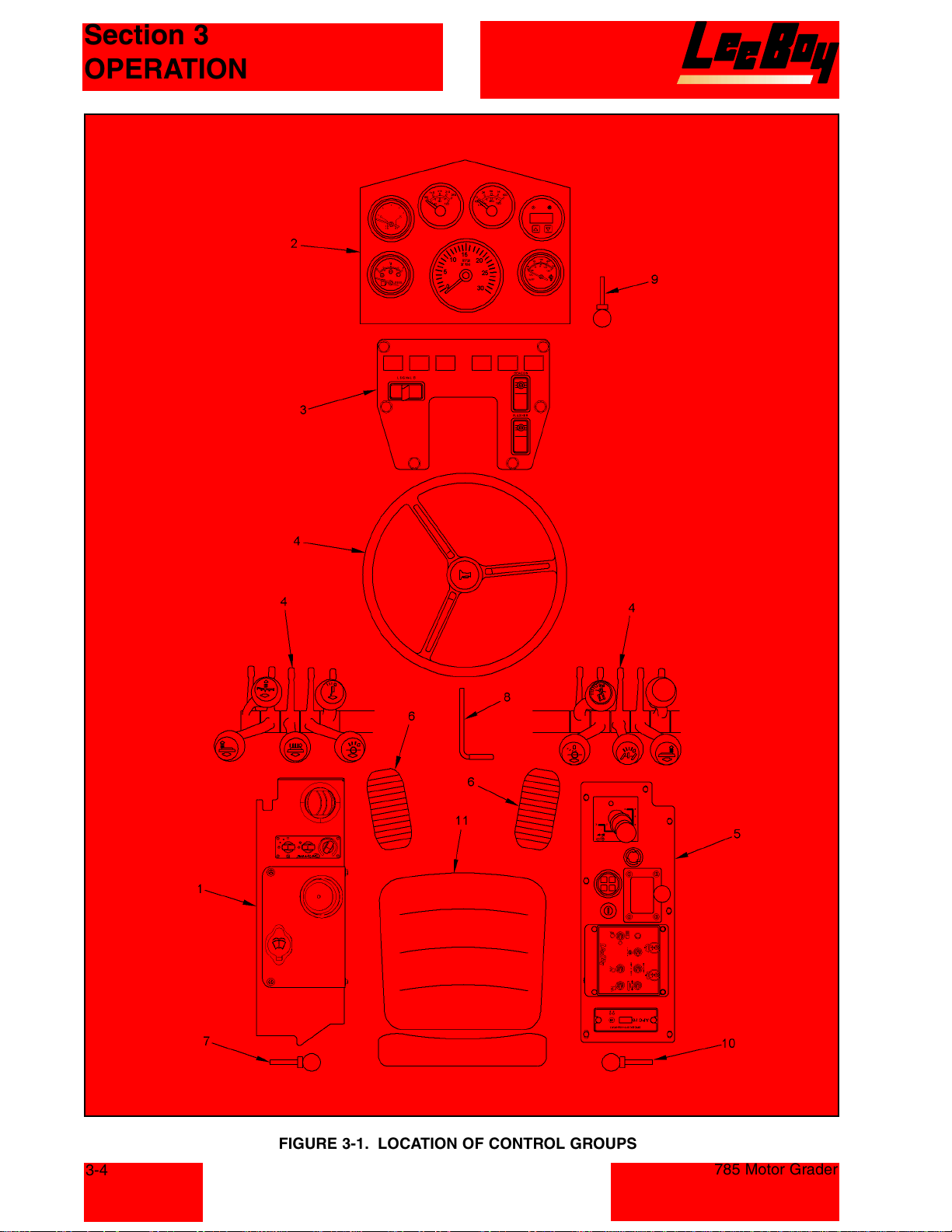
FIGURE 3-1. LOCATION OF CONTROL GROUPS
785 Motor Grader
Courtesy of Machine.Market
Page 23
Section 3
OPERATION
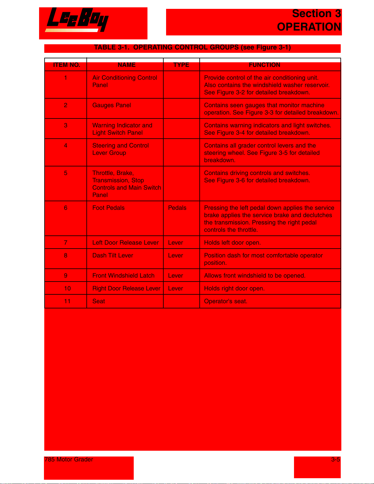
TABLE 3-1. OPERATING CONTROL GROUPS (see Figure 3-1)
ITEM NO. NAME TYPE FUNCTION
1 Air Conditioning Control Provide control of the air conditioning unit.
Panel Also contains the windshield washer reservoir.
See Figure 3-2 for detailed breakdown.
2 Gauges Panel Contains seen gauges that monitor machine
operation. See Figure 3-3 for detailed breakdown.
3 Warning Indicator and Contains warning indicators and light switches.
Light Switch Panel See Figure 3-4 for detailed breakdown.
4 Steering and Control Contains all grader control levers and the
Lever Group steering wheel. See Figure 3-5 for detailed
breakdown.
5 Throttle, Brake, Contains driving controls and switches.
Transmission, Stop See Figure 3-6 for detailed breakdown.
Controls and Main Switch
Panel
6 Foot Pedals Pedals Pressing the left pedal down applies the service
brake applies the service brake and declutches
the transmission. Pressing the right pedal
controls the throttle.
7 Left Door Release Lever Lever Holds left door open.
8 Dash Tilt Lever Lever Position dash for most comfortable operator
position.
9 Front Windshield Latch Lever Allows front windshield to be opened.
10 Right Door Release Lever Lever Holds right door open.
11 Seat Operator's seat.
785 Motor Grader
3-5
Courtesy of Machine.Market
Page 24
Section 3
OPERATION
3-6
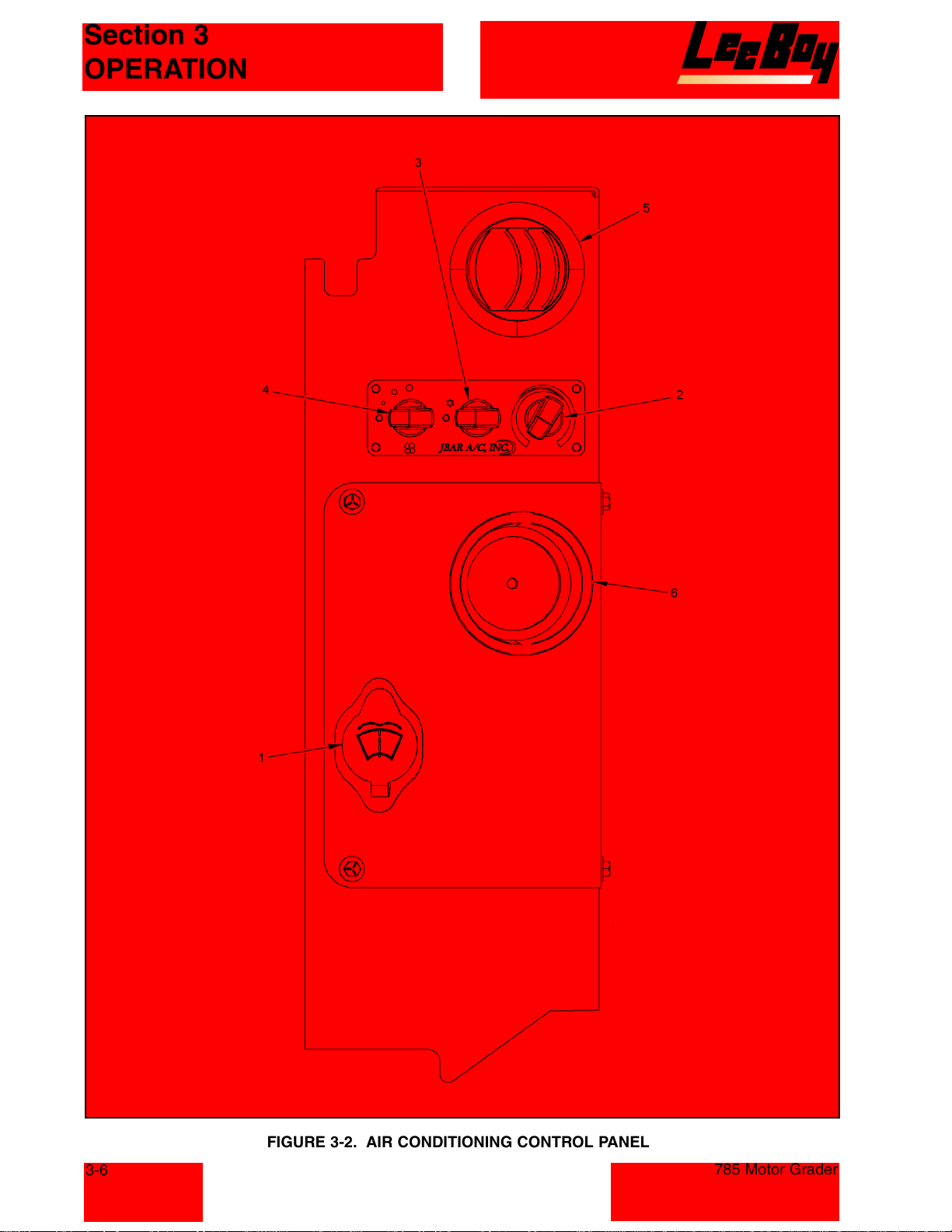
FIGURE 3-2. AIR CONDITIONING CONTROL PANEL
785 Motor Grader
Courtesy of Machine.Market
Page 25
Section 3
OPERATION
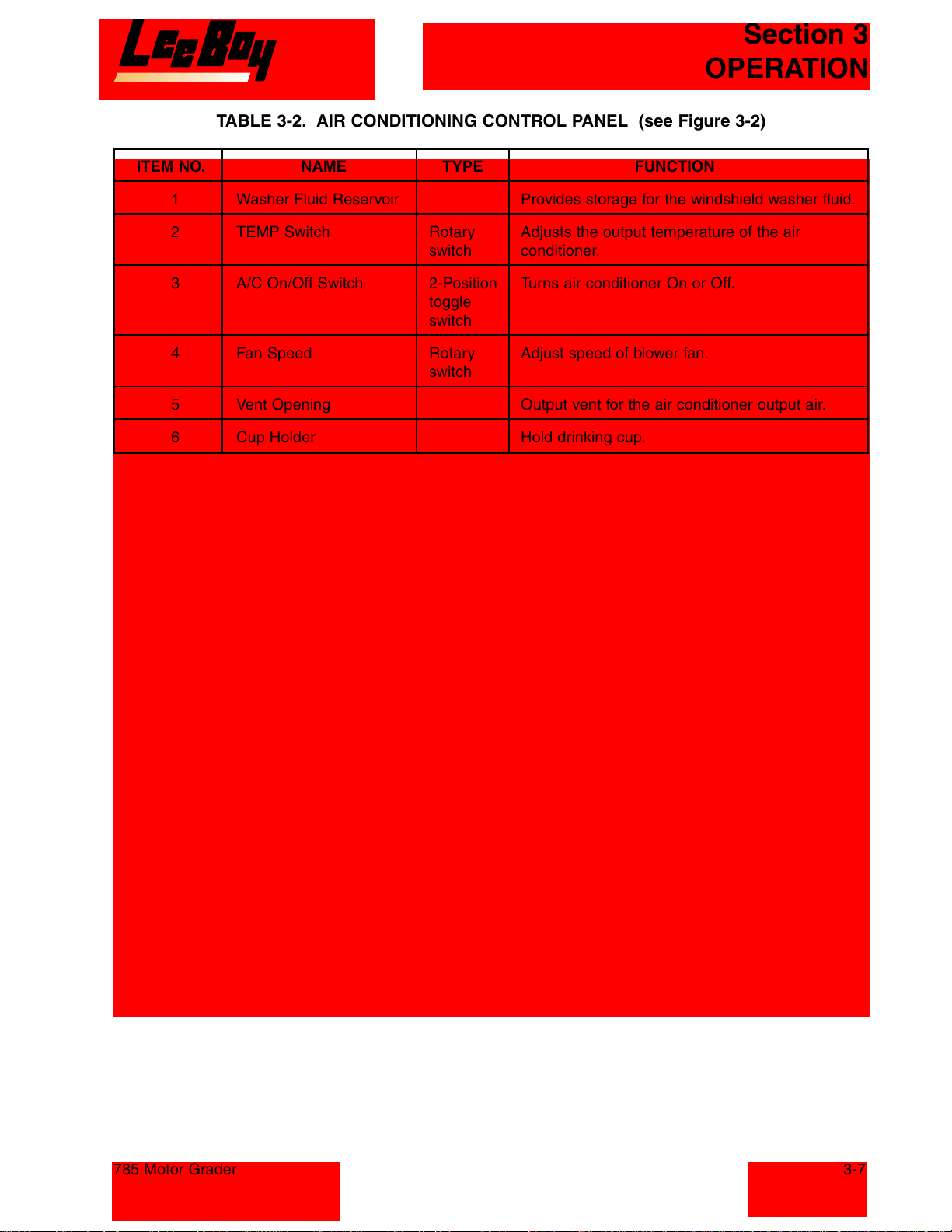
TABLE 3-2. AIR CONDITIONING CONTROL PANEL (see Figure 3-2)
ITEM NO. NAME TYPE FUNCTION
1 Washer Fluid Reservoir Provides storage for the windshield washer fluid.
2 TEMP Switch Rotary Adjusts the output temperature of the air
switch conditioner.
3 A/C On/Off Switch 2-Position Turns air conditioner On or Off.
toggle
switch
4 Fan Speed Rotary Adjust speed of blower fan.
switch
5 Vent Opening Output vent for the air conditioner output air.
6 Cup Holder Hold drinking cup.
785 Motor Grader
3-7
Courtesy of Machine.Market
Page 26
Section 3
OPERATION
3-8
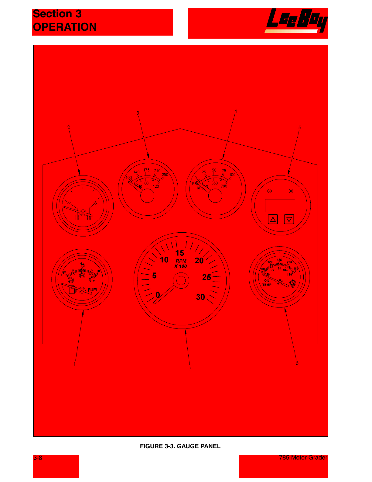
FIGURE 3-3. GAUGE PANEL
785 Motor Grader
Courtesy of Machine.Market
Page 27
Section 3
OPERATION
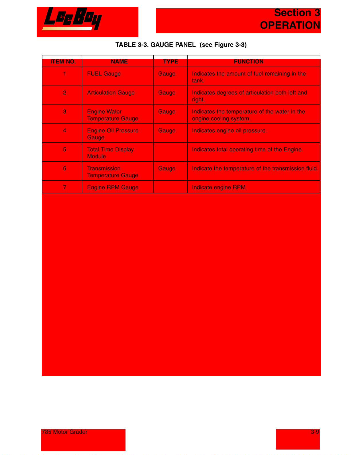
TABLE 3-3. GAUGE PANEL (see Figure 3-3)
ITEM NO. NAME TYPE FUNCTION
1 FUEL Gauge Gauge Indicates the amount of fuel remaining in the
tank.
2 Articulation Gauge Gauge Indicates degrees of articulation both left and
right.
3 Engine Water Gauge Indicates the temperature of the water in the
Temperature Gauge engine cooling system.
4 Engine Oil Pressure Gauge Indicates engine oil pressure.
Gauge
5 Total Time Display Indicates total operating time of the Engine.
Module
6 Transmission Gauge Indicate the temperature of the transmission fluid.
Temperature Gauge
7 Engine RPM Gauge Indicate engine RPM.
785 Motor Grader
3-9
Courtesy of Machine.Market
Page 28
Section 3
OPERATION
3-10
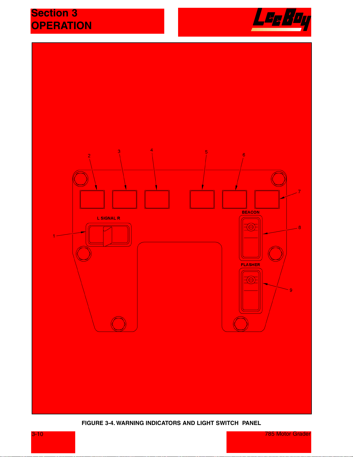
FIGURE 3-4. WARNING INDICATORS AND LIGHT SWITCH PANEL
785 Motor Grader
Courtesy of Machine.Market
Page 29
Section 3
OPERATION
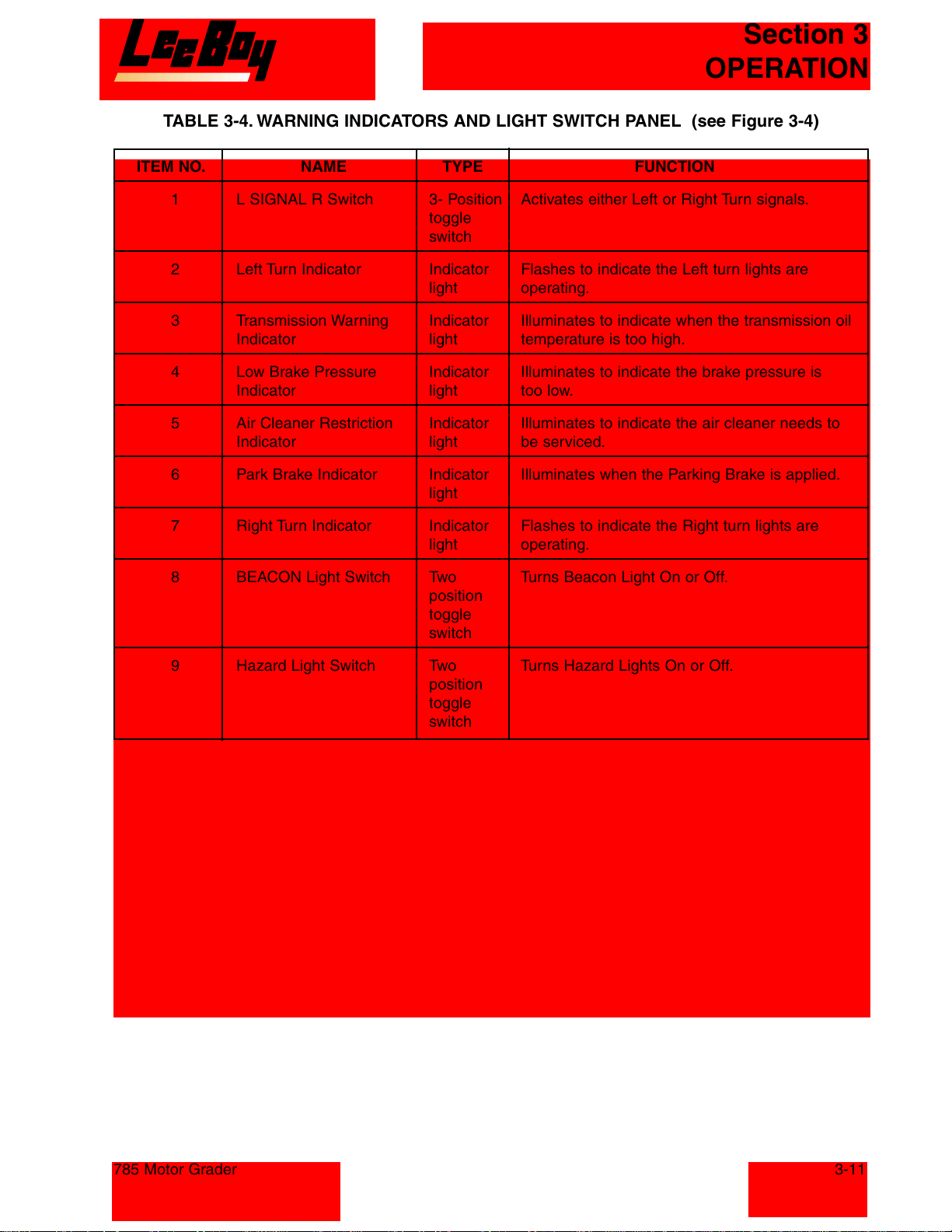
TABLE 3-4. WARNING INDICATORS AND LIGHT SWITCH PANEL (see Figure 3-4)
ITEM NO. NAME TYPE FUNCTION
1 L SIGNAL R Switch 3- Position Activates either Left or Right Turn signals.
toggle
switch
2 Left Turn Indicator Indicator Flashes to indicate the Left turn lights are
light operating.
3 Transmission Warning Indicator Illuminates to indicate when the transmission oil
Indicator light temperature is too high.
4 Low Brake Pressure Indicator Illuminates to indicate the brake pressure is
Indicator light too low.
5 Air Cleaner Restriction Indicator Illuminates to indicate the air cleaner needs to
Indicator light be serviced.
6 Park Brake Indicator Indicator Illuminates when the Parking Brake is applied.
light
7 Right Turn Indicator Indicator Flashes to indicate the Right turn lights are
light operating.
8 BEACON Light Switch Two Turns Beacon Light On or Off.
position
toggle
switch
9 Hazard Light Switch Two Turns Hazard Lights On or Off.
position
toggle
switch
785 Motor Grader
3-11
Courtesy of Machine.Market
Page 30
Section 3
OPERATION
3-12
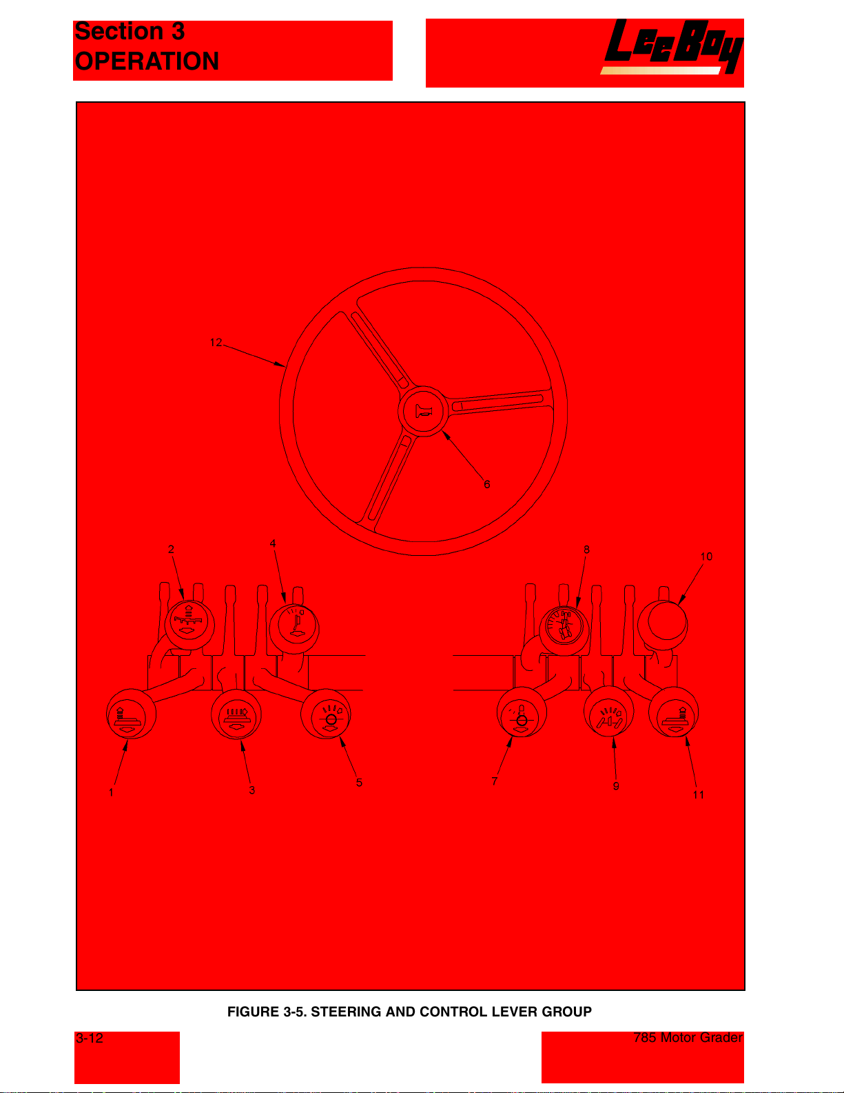
FIGURE 3-5. STEERING AND CONTROL LEVER GROUP
785 Motor Grader
Courtesy of Machine.Market
Page 31
Section 3
OPERATION
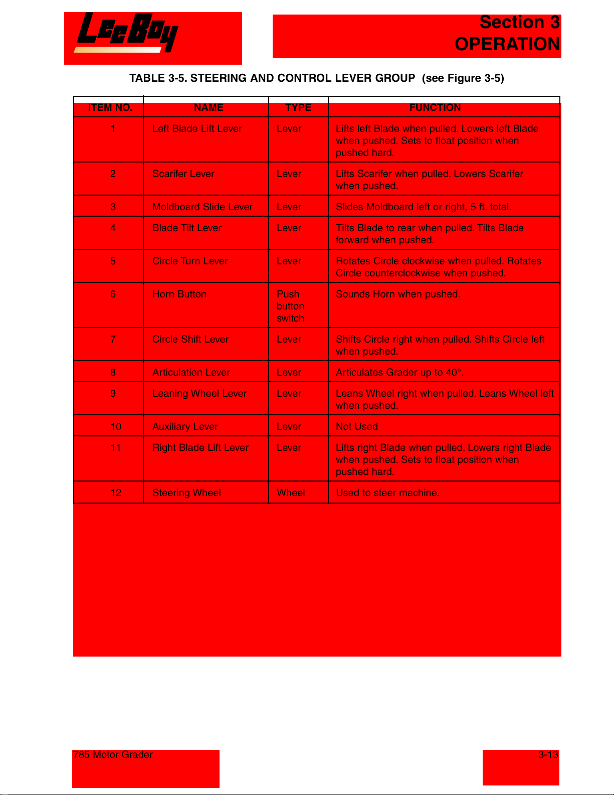
TABLE 3-5. STEERING AND CONTROL LEVER GROUP (see Figure 3-5)
ITEM NO. NAME TYPE FUNCTION
1 Left Blade Lift Lever Lever Lifts left Blade when pulled. Lowers left Blade
when pushed. Sets to float position when
pushed hard.
2 Scarifer Lever Lever Lifts Scarifer when pulled. Lowers Scarifer
when pushed.
3 Moldboard Slide Lever Lever Slides Moldboard left or right, 5 ft. total.
4 Blade Tilt Lever Lever Tilts Blade to rear when pulled. Tilts Blade
forward when pushed.
5 Circle Turn Lever Lever Rotates Circle clockwise when pulled. Rotates
Circle counterclockwise when pushed.
6 Horn Button Push Sounds Horn when pushed.
button
switch
7 Circle Shift Lever Lever Shifts Circle right when pulled. Shifts Circle left
when pushed.
8 Articulation Lever Lever Articulates Grader up to 40°.
9 Leaning Wheel Lever Lever Leans Wheel right when pulled. Leans Wheel left
when pushed.
10 Auxiliary Lever Lever Not Used
11 Right Blade Lift Lever Lever Lifts right Blade when pulled. Lowers right Blade
when pushed. Sets to float position when
pushed hard.
12 Steering Wheel Wheel Used to steer machine.
785 Motor Grader
3-13
Courtesy of Machine.Market
Page 32
Section 3
OPERATION
3-14
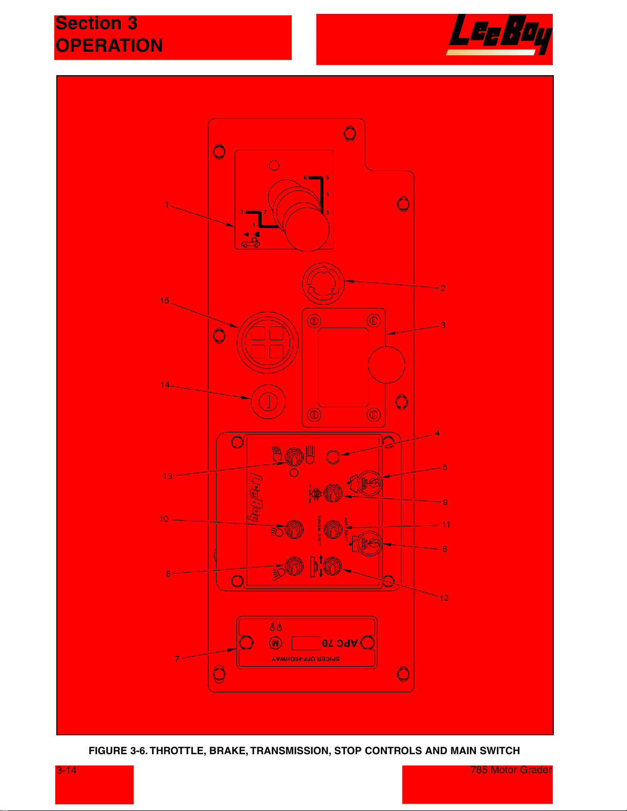
FIGURE 3-6. THROTTLE, BRAKE,TRANSMISSION, STOP CONTROLS AND MAIN SWITCH
785 Motor Grader
Courtesy of Machine.Market
Page 33
Section 3
OPERATION
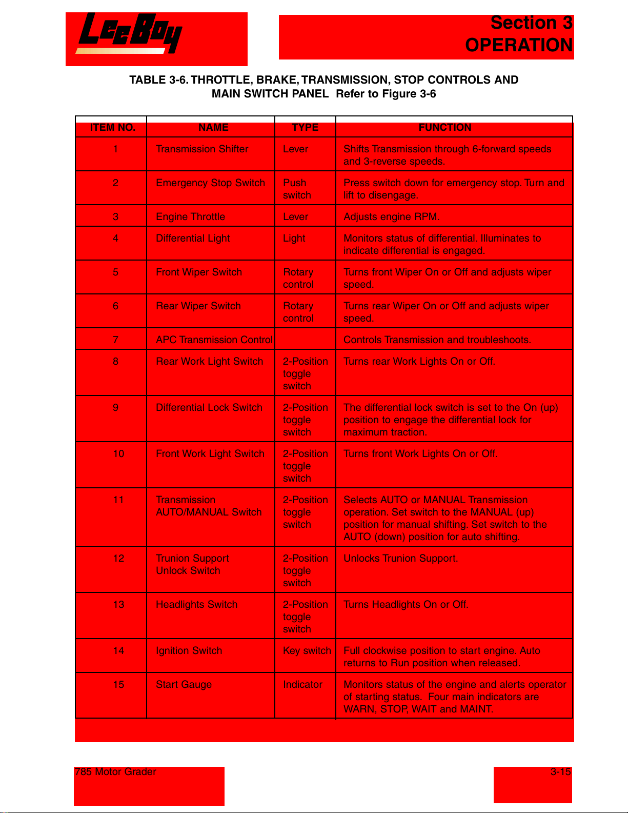
TABLE 3-6. THROTTLE, BRAKE, TRANSMISSION, STOP CONTROLS AND
MAIN SWITCH PANEL Refer to Figure 3-6
ITEM NO. NAME TYPE FUNCTION
1 Transmission Shifter Lever Shifts Transmission through 6-forward speeds
and 3-reverse speeds.
2 Emergency Stop Switch Push Press switch down for emergency stop. Turn and
switch lift to disengage.
3 Engine Throttle Lever Adjusts engine RPM.
4 Differential Light Light Monitors status of differential. Illuminates to
indicate differential is engaged.
5 Front Wiper Switch Rotary Turns front Wiper On or Off and adjusts wiper
control speed.
6 Rear Wiper Switch Rotary Turns rear Wiper On or Off and adjusts wiper
control speed.
7 APC Transmission Control Controls Transmission and troubleshoots.
8 Rear Work Light Switch 2-Position Turns rear Work Lights On or Off.
toggle
switch
9 Differential Lock Switch 2-Position The differential lock switch is set to the On (up)
toggle position to engage the differential lock for
switch maximum traction.
10 Front Work Light Switch 2-Position Turns front Work Lights On or Off.
toggle
switch
11 Transmission 2-Position Selects AUTO or MANUAL Transmission
AUTO/MANUAL Switch toggle operation. Set switch to the MANUAL (up)
switch position for manual shifting. Set switch to the
AUTO (down) position for auto shifting.
12 Trunion Support 2-Position Unlocks Trunion Support.
Unlock Switch toggle
switch
13 Headlights Switch 2-Position Turns Headlights On or Off.
toggle
switch
14 Ignition Switch Key switch Full clockwise position to start engine. Auto
15 Start Gauge Indicator Monitors status of the engine and alerts operator
785 Motor Grader
returns to Run position when released.
of starting status. Four main indicators are
WARN, STOP, WAIT and MAINT.
3-15
Courtesy of Machine.Market
Page 34
Section 3
OPERATION
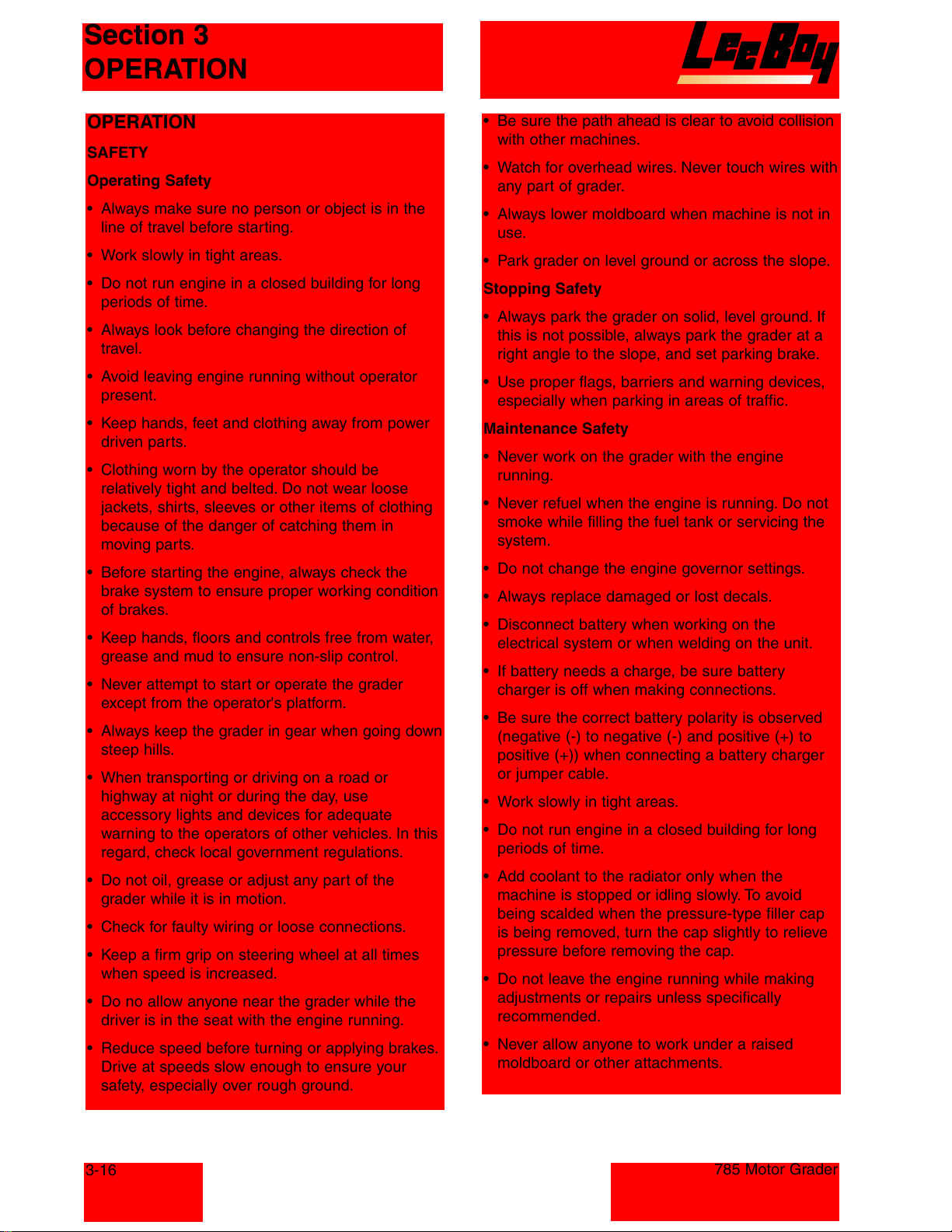
OPERATION
SAFETY
Operating Safety
• Always make sure no person or object is in the
line of travel before starting.
• Work slowly in tight areas.
• Do not run engine in a closed building for long
periods of time.
• Always look before changing the direction of
travel.
• Avoid leaving engine running without operator
present.
• Keep hands, feet and clothing away from power
driven parts.
• Clothing worn by the operator should be
relatively tight and belted. Do not wear loose
jackets, shirts, sleeves or other items of clothing
because of the danger of catching them in
moving parts.
• Before starting the engine, always check the
brake system to ensure proper working condition
of brakes.
• Keep hands, floors and controls free from water,
grease and mud to ensure non-slip control.
• Never attempt to start or operate the grader
except from the operator's platform.
• Always keep the grader in gear when going down
steep hills.
• When transporting or driving on a road or
highway at night or during the day, use
accessory lights and devices for adequate
warning to the operators of other vehicles. In this
regard, check local government regulations.
• Do not oil, grease or adjust any part of the
grader while it is in motion.
• Check for faulty wiring or loose connections.
• Keep a firm grip on steering wheel at all times
when speed is increased.
• Do no allow anyone near the grader while the
driver is in the seat with the engine running.
• Reduce speed before turning or applying brakes.
Drive at speeds slow enough to ensure your
safety, especially over rough ground.
• Be sure the path ahead is clear to avoid collision
with other machines.
• Watch for overhead wires. Never touch wires with
any part of grader.
• Always lower moldboard when machine is not in
use.
• Park grader on level ground or across the slope.
Stopping Safety
• Always park the grader on solid, level ground. If
this is not possible, always park the grader at a
right angle to the slope, and set parking brake.
• Use proper flags, barriers and warning devices,
especially when parking in areas of traffic.
Maintenance Safety
• Never work on the grader with the engine
running.
• Never refuel when the engine is running. Do not
smoke while filling the fuel tank or servicing the
system.
• Do not change the engine governor settings.
• Always replace damaged or lost decals.
• Disconnect battery when working on the
electrical system or when welding on the unit.
• If battery needs a charge, be sure battery
charger is off when making connections.
• Be sure the correct battery polarity is observed
(negative (-) to negative (-) and positive (+) to
positive (+)) when connecting a battery charger
or jumper cable.
• Work slowly in tight areas.
• Do not run engine in a closed building for long
periods of time.
• Add coolant to the radiator only when the
machine is stopped or idling slowly. To avoid
being scalded when the pressure-type filler cap
is being removed, turn the cap slightly to relieve
pressure before removing the cap.
• Do not leave the engine running while making
adjustments or repairs unless specifically
recommended.
• Never allow anyone to work under a raised
moldboard or other attachments.
3-16
785 Motor Grader
Courtesy of Machine.Market
Page 35
Section 3
OPERATION
INSPECTION
Introduction
Daily inspection and servicing at required intervals
is necessary for the safe operation and maximum
service life of the LeeBoy Model 785 Motor Grader
and its components.
WARNING: Do not smoke when performing
inspections or servicing unit.
Flammable liquids are present.
Receiving Inspection
When the grader arrives at a new site, the grader
should be inspected for road hazards or vandalism
that could occur during transportation and could
have damaged the machine. Perform the following
inspections and correct any faulty condition using
the procedures in the MAINTENANCE section of
this manual.
1. Check for any missing or damaged parts
2. Check Engine Oil Level
3. Check Transmission Oil Level
4. Check Differential Oil Level
5. Check Tandem Oil Level
6. Check Gear Hub Oil Level
7. Check Coolant in Radiator
8. Check Fuel Level
9. Check Tires for Cuts
10. Have a qualified Operator Test All Functions
Inspection Before Initial Start-Up
The following inspection by the operator is
essential. This inspection should be performed on
a daily basis. Procedures for performing the
inspections are described in the MAINTENANCE
Section of this manual.
Visually inspect the unit for familiarization and to
check its general condition. Continue with a check
of special systems and components.
INSPECTED ITEM PROCEDURE
Loose or Missing Hardware Check all visually accessible areas for loose or missing hardware.
Any loose hardware should be torqued to the correct value.
Check for Worn or Damaged Parts Check all accessible parts for wear or damage. Replace any part
showing excessive wear or damage.
Check for Leaks Check all hydraulic lines, fuel lines, and tanks for leaks.
Check Engine Oil Level Check that engine oil is between the marks on the dipstick.
Check Transmission Oil Level Check oil level with dip stick. Transmission oil level must be hot
and engine running with transmission in Neutral when checking.
Be sure sufficient oil is present.
Check Differential Oil Level Check that differential oil level is at proper level.
Check Tandem Oil Level Check that differential oil level is at proper level.
Check Planetary Hub Oil Level Check that gear oil level is at proper level.
Check Coolant in Radiator WARNING: Never remove radiator cap when hot. Serious
burns can result from the hot liquid.
Allow coolant to cool down before checking level.
Check Fuel Level Check fuel gauge for sufficient fuel level.
Check Hydraulic Oil Level Check at sight gauge on side of hydraulic oil tank.
Batteries Make sure that all cables are tight and clean. Check for corrosion
on the battery terminals.
785 Motor Grader
Courtesy of Machine.Market
3-17
Page 36
Section 3
OPERATION
INSPECTED ITEM PROCEDURE
Air Cleaner Check the air filter element and hose connections. Air cleaner has
both a primary and secondary filter.
Check Lugs on All Wheels Check for loose appearing lugs. If any lug is suspect, tighten to
the correct torque.
Check Tire Pressure Check for correct tire pressure in all six tires.
Drain Plugs Make sure plugs are in and tight.
Engine Belt Check for proper tension of belt.
Grease Fittings Make sure the fittings are greased and in good working order.
Check Steering Joint and Welds Check for any cracks.
Check all Lights for Proper Operation Test the signal, brake, flasher, work, strobe and driving lights for
proper operation.
Check Parking Brake and Check that both brakes are working properly.
Service Brake
Test All Functions Have a Qualified Operator Test all Functions before allowing
grader to be placed in operation. If any function is not performing
properly, take machine out of service until the faulty condition has
been corrected.
Preliminary Procedures
Adjusting Front Console
The front console can be positioned using the
Dash Tilt Lever (8, Figure 3-1) Adjust for best
operator comfort.
Air Conditioner
The air conditioner controls are located to the left
of the operator. Proceed as follows to control the
air conditioner.
1. Set the A/C ON-OFF switch (3, Figure 3-2) to
the ON position.
2. Adjust the vent (5) for the desired opening.
3. Adjust the Temperature switch (2) for the
desired temperature.
4. Adjust the Fan Speed (4) for the desired level.
Opening Windshield
The windshield can be opened by using the front
windshield latch (9, Figure 3-1).
Cab Door Release Levers
Both the right door release lever (10, Figure 3-1),
and left door release lever (7) will hold the
associated door open.
Cab Light
The cab light is located on the cab ceiling. The
switch for the cab light is located on the light
assembly.
Console Light
The console lights illuminate the gauges for
reading at low light levels. These are turned on
when the headlight switch is set to the ON (up)
position.
5. To turn the air conditioner off set the A/C
On/Off Switch to the OFF position.
Defroster Fan
The defroster fan is used to help defrost the front
windshield. The switch for the defroster fan is
located on the fan at the upper left of the operator.
3-18
DRIVING THE MACHINE
Start-up Procedure
CAUTION: NEVER start engine unless
properly seated in the operators
seat, seat belt is secured, and
transmission is in Neutral.
785 Motor Grader
Courtesy of Machine.Market
Page 37
Section 3
OPERATION
1. Fasten seat belt.
2. Turn MASTER Switch to the ON position.
3. Set Park Brake (2, Figure 3-6) to ON position.
4. Set Transmission Shifter (1) to Neutral position.
5. Set Throttle (3) to Idle position.
WARNING: Do not move the throttle lever from
the idle position while cranking the
engine. This can result in engine
over-speed and severe damage to
the engine.
CAUTION: To prevent damage to the starting
motor, do not engage the starting
motor for more than 30 seconds.
Wait two minutes between each
attempt to start.
6. Turn Key ON and wait for all lights to turn off on
the Start Gauge.
7. Turn the Ignition switch to the Start position. If
the engine does not start after three attempts,
check the fuel supply system.
NOTE: The engine must have adequate oil
pressure within 15 seconds after
starting. If there is no oil pressure
indicated on the gauge within 15
seconds, shut off the engine
immediately to avoid engine damage.
8. Idle the engine for 3 to 5 minutes before
operating with a load.
9. After starting a cold engine, increase the
engine speed (rpm) slowly to provide adequate
lubrication to the bearings and to allow the oil
pressure to stabilize.
The grader electrical system is 12 volt negative
ground and uses two batteries in parallel. When
connecting a booster battery be sure the negative
terminal of the booster battery is connected to the
negative terminal of the grader battery and positive
terminal of the booster battery is connected to the
positive terminal of the grader battery
Engine Shutdown
NOTE: Before leaving the operator's seat
perform the following shut-down
procedure.
1. Place throttle in idle position.
2. Place Transmission Shifter in Neutral position.
3. Set Park brake.
4. Lower all tools (blades).
5. Place all light switches to the off position.
6. Turn Ignition switch to the off position.
7. Turn the Master switch to the off position.
Auto Mode
Moving Forward/Reverse.
1. Start engine as described in START-UP
PROCEDURE.
2. Hold foot on brake.
3. Check that area is clear.
4. Lift tools (blades).
NOTE: Make sure blade is not near a tire.
5. Set MANUAL/AUTO switch to the AUTO position.
6. Set throttle to the idle position.
CAUTION: Do not operate engine at low idle
for long periods with engine
coolant temperature below the
minimum specification. This can
result in the following:
• Fuel dilution of the lubricating oil.
• Cylinder head valve sticking.
• Reduced performance.
Using Booster Batteries
CAUTION: Explosive gases are produced
while batteries are in use or being
charged. Keep flames or sparks
away from battery area. Booster
batteries must be connected
properly to prevent dangerous
sparking.
785 Motor Grader
NOTE: If throttle is not at full Idle, controller
will not engage transmission.
7. Set Transmission Shifter to the desired gear.
8. Release foot brake.
9. Wait until transmission engages.
10. Increase the engine RPM with the throttle.
NOTE: As the engine RPM's increase the
transmission will begin to shift until it
reaches the selected gear.
Stopping
1. Apply foot brake.
2. Move throttle back to the idle position.
3. Set Transmission Shifter to Neutral position.
3-19
Courtesy of Machine.Market
Page 38
Section 3
OPERATION
Stopping and Restarting
1. Apply foot brake.
2. Set Throttle to the idle position.
3. Release foot brake.
4. Apply Throttle.
NOTE: Transmission will not engage if throttle
is not at full Idle position.
Manual Mode
Moving Forward/Reverse
1. Start engine as described in START-UP
PROCEDURE
2. Hold foot on brake.
3. Check that area is clear.
4. Lift tools (blades).
NOTE: Make sure blade is not near a tire.
5. Set MANUAL/AUTO switch to the MANUAL
position.
6. Set throttle to the idle position.
NOTE: If throttle is not at full Idle, controller
will not engage transmission.
7. Set Transmission Shifter to 1st gear forward or
reverse as desired.
8. Wait until transmission engages.
9. Release foot brake.
10. Increase the engine RPM with the throttle and
shift gears as desired..
NOTE: Grader can be down shifted on the go.
The computer will control and protect
the transmission.
NOTE: When switching directions, the
controller will try to start in 3rd gear.
Do not select 1st or 2nd gear unless
you need that gear.
Stopping
Stopping and Restarting
1. Apply foot brake.
2. Set Throttle to the idle position.
3. Release foot brake.
4. Apply Throttle.
NOTE: Transmission will not engage if throttle
is not at full Idle position.
OPERATING THE MACHINE
Blade Lift Levers
The Blades Lift levers (1 and 11, Figure 3-5)
control the lifting and lowering of the Blade.
1. Pull levers to raise the blade.
2. Push levers to lower the blade.
3. Push levers fully forward into detent to float the
blade. Pull levers back to manually release the
float.
Blade float allows blade to float over hard surfaces.
Moldboard Slide Lever
The Moldboard Slide lever (3, Figure 3-5) is
located in the left lever group.
1. Pull lever to shift blade right.
2. Push lever to shift blade left.
Blade Tilt Lever
The Blade Tilt lever (4, Figure 3-5) is used to tilt
the blade.
1. Pull lever to tilt blade to the rear.
2. Push lever to tilt blade forward.
Circle Turn Lever
The Circle Turn lever (5, Figure 3-5) is used to
rotate the circle.
1. Pull lever to turn circle clockwise.
2. Push lever to turn circle counterclockwise.
Circle Shift Lever
The Circle Shift lever (7, Figure 3-5) is used to shift
the circle left or right.
1. Apply foot brake.
2. Move throttle back to the idle position.
3. Set Transmission Shifter to Neutral position.
3-20
1. Pull lever to shift circle right.
2. Push lever to shift circle left.
Articulation Lever
The Articulation lever (8, Figure 3-5) is used to set
the grader articulation up to 40°.
1. Pull lever for right articulation
785 Motor Grader
Courtesy of Machine.Market
Page 39
Section 3
OPERATION
2. Push lever for left articulation.
NOTE: Amount of articulation is displayed on
the Articulation gauge (2, Figure 3-3).
Leaning Wheel Lever
The Leaning Wheel lever (9, Figure 3-5) is used to
set the amount of wheel lean.
1. Pull lever to lean wheels right.
2. Push lever to lean wheel left.
Scarifer Lever
The Scarifer lever (2, Figure 3-5) is used to raise or
lower the Scarifer.
1. Pull lever to lift Scarifier.
2. Push lever to lower Scarifer.
Differential Lock Switch
NOTE: The differential lock is used when
conditions require maximum traction.
The Differential Lock switch (9, Figure 3-6) is used
to help with traction. When the switch is set to the
ON (up) position the differential lock is engaged.
The differential lock can be locked or release while
grader is in motion. Releasing the differential lock
will allow shorter turns.
Moving Blade to Bank Position
The following procedure is for moving blade to the
right. Use opposite functions to move to the left.
1. Position the circle slightly to the right of center.
2. Shift blade right.
3. Lower blade to ground.
4. Set blades to the float position.
5. Disengage lift arm locking pin.
6. Retract left lift cylinder and circle side shift
cylinder and extend right lift cylinder to rotate
lift arms.
7. Align lift arm indicator with desired locking
position and engage locking pin.
8. Use lift cylinders and circle side shift cylinder to
lift blade off ground (4 - 5 in. [100 - 125 mm]).
9. Rotate blade counterclockwise to put right end
of blade forward.
10. Retract right lift cylinder, extend left lift cylinder,
rotate circle, adjust circle side shift cylinder and
pitch, and side shift blade to obtain desired
position.
11. Follow steps in reverse order to move blade out
of the bank position.
Steering
The grader is steered using the steering wheel (12,
Figure 3-5). The machine can be steered in the
straight frame or articulated position. The straight
frame position is most often used for long runs. The
articulated position shortens turns and also can be
used to counteract the side thrust in normal
grading.
Blade Side Thrust
When a load is being pushed, the front of the
grader tends to swing toward the toe of the blade.
This can be counteracted as follows:
1. Articulate machine toward the toe of the blade.
2. Lean top of front wheels toward heel
(discharge side) of blade.
Blade Pitch Adjustment
Use the upright position of the Moldboard for
normal grading. Position the blade so that the top
edge is vertical or slightly ahead of bottom edge.
This places the cutting edge at the best cutting
angle.
Use a backward pitch of the Moldboard for greater
cutting ability. This will cause the cutting edge to
dig in.
NOTE: Dirt may build up and pile into circle
due to decreased rolling action. Adjust
position as required.
For better mixing and rolling action, pitch
Moldboard ahead of vertical position. When
spreading material moldboard should be tipped
further forward. This helps compact material and fill
low spots. Use only as much forward tilt as
necessary for the job.
Pile Spreading
1. Set moldboard at right angles to the direction
of travel and shift the moldboard toward pile.
2. Tilt blade slightly forward.
3. Raise blade for the desired depth.
4. Shift circle toward pile.
5. Lean front wheels slightly away from pile.
NOTE: The material spread in each pass will
be limited by the power and traction of
the grader.
785 Motor Grader
3-21
Courtesy of Machine.Market
Page 40
Section 3
OPERATION
Back Filling
The moldboard can be used to backfill a trench
and the rear tandem can be used to compact the
backfill material.
Vee Ditching
Vee ditching requires at least three passes; The
first pass shapes the ditch, the second pass
deepens the ditch, and the third pass cleans up the
materials. The material is then spread to form the
roadbed and shoulder. The final step is cutting the
back slope.
First Pass
1. Center the circle.
2. Position toe of blade just outside edge of front
tire.
3. Tilt blade and pitch forward until top of blade is
in line with center of front tire.
4. Raise blade heel just ahead of tandem tires so
dirt will spill out between them.
5. Lead front wheels slightly toward discharge end
of blade.
6. Engage the differential lock.
7. Travel in 1st or 2nd gear.
8. Make first pass very shallow in order to
establish line of ditch.
Second Pass
Position wheels in vee ditch made on first pass to
compensate for side thrust.
NOTE: This allows a deeper cut at higher
speed during second pass.
Third Pass
This is the clean-up pass. The cleanup pass is
used to reduce the build-up of dirt between the
tandem wheels from successive passes. After the
cleanup pass the material can be spread to
establish the roadbed and the shoulder.
1. Sideshift circle and blade toward ditch.
2. Position front wheels outside windrow.
3. Set blade at an angle that positions heel
between tandems with blade pitched slightly
forward.
4. Position toe of blade well beyond windrow to
minimize spillage back into the vee ditch;.
5. Articulate grader slightly to deposit windrow
between tandems.
Spreading Material
1. Use a straight frame position to spread
windrow left from cleanup pass.
2. Position circle and moldboard to deposit
material evenly. Use material to establish
roadbed and shoulder.
Cutting Back Slope
1. Sideshift circle and blade toward bank.
2. Position heel of blade in center of rear tire.
3. Pitch blade slightly forward.
4. Blade angle is toward direction of travel at
approximately 40° depending upon degree and
height of slope.
5. Drive wheels of machine in established vee
ditch.
NOTE: This will deposit dirt from back slope
slightly up onto shoulder slope when a
cleanup pass will pull it up onto
roadbed for spreading.
6. To finish vee ditch; pull windrow up from
shoulder slope, clean it away from edge of
ditch and spread it.
7. Repeat steps as necessary.
Cleaning Ditches
If ditch is soft or wet and can not support the full
weight of the grader, proceed as follows:
1. Offset tandems so that the tandems ride on
shoulder of road.
2. Lift material from ditch and dump it outside of
tandems.
3. By articulating tandems on road and front
wheels into ditch, the grader can be backed up
until toe of blade is at end of culvert. Then start
cut, windrowing material onto shoulder of
roadbed.
NOTE: When filling washouts on existing back
slopes, blade can be angled back and
side-shifted enough so that material
can be rolled up slope.
Road Crowning
1. Blade material inward from shoulders of
ditches.
2. Cut top of crown with blade at a 0° angle, or a
slight angle to side cast material to whichever
side might require it.
3-22
785 Motor Grader
Courtesy of Machine.Market
Page 41
Section 3
OPERATION
3. Spread windrows by putting blade at an angle
of 10° - 25° toward center.
4. Keep blade above level of undisturbed surface
so as to avoid collision with solid objects such
as rocks in roadbed.
5. Perform crowning operation at relatively high
speed. High speed causes loose material to be
thrown from the blade, which feathers the
material and blends it at the top.
NOTE: Any ridge that is left in the center can
then be spread out at high speed with
a straight blade.
Bank Cutting
1. The first pass should be at the base of the
bank to level and smooth a platform for the
grader.
2. Locate heel of blade in front of center of rear
wheel.
3. Shift toe of blade forward.
4. Tilt blade forward.
5. Lean wheels slightly toward bank.
5. Lean front wheels toward slope on second
pass.
6. To help prevent front end from drifting down,
position upper front wheel above windrow.
7. To increase stability of machine, articulate
tandems down slope.
8. Position toe of blade forward and angled so
material is spilled off heel of blade slightly
between or under tandems. Set blade pitch
ahead of vertical plane and side-shift circle
toward the upside.
9. Repeat the procedure until dirt is deposited at
toe of slope. Establish toe of slope by cleaning
windrow away from bottom.
10. When working on steep slopes, the differential
may be locked or unlocked at the operator's
preference.
CAUTION: A rollover with the grader
articulated is very unlikely;
however, extreme caution should
always be used when working on
slopes steeper than three to one.
6. Position grader frame straight with all wheels at
base of bank, or if more reach is needed,
articulate slightly to position front inside wheel
on bank.
Three methods can be used to vary depth of cut
these are;
1. Leaning wheels away or toward the bank.
2. Maneuvering lift cylinders.
3. Changing blade pitch.
NOTE: After first bank cut, it may be
necessary to clean loose material away
from bottom of bank.
Slope Work
1. The first pass should be made from above the
slope, if possible, to establish angle.
2. Side-shift the circle and the blade toward slope.
3. Set blade angle slightly toward rear of machine
with a slight forward tilt.
4. Reach the blade as far down slope as possible
and make first pass.
Cul-De-Sacs
1. Shift circle to outside.
2. Articulate grader to inside.
3. Tilt blade forward about 5° - 10°.
4. Travel in 1st gear, fast idle with front wheels
leaning toward direction of turn.
NOTE: After curb is poured, back fill against
the outside of curb to give support.
To finish grading, as the turns become shorter on
each succeeding pass, the circle and moldboard
are shifted toward the center. Then any excess
material left in the middle can be moved out of the
cul-de-sac.
LOADING GRADER ON A TRAILER
1. Place chocks against truck wheels.
CAUTION: Ramps must be strong enough to
carry the weight of the grader. Also
the ramp must have a low angle,
and correct height.
NOTE: The grader can be in straight frame
position or articulated for extra reach.
785 Motor Grader
2. Use a ramp or loading dock. Load and unload
grader on a level surface.
3-23
Courtesy of Machine.Market
Page 42
Section 3
OPERATION
3. If grader is equipped with rollover protective
structure (ROPS), fasten seat belt before
starting engine.
4. Drive grader slowly onto ramps. Centerline of
grader should be over the centerline of the
trailer.
5. Before leaving operator’s seat:
a. Lower all equipment onto blocks on trailer
bed.
NOTE: Blade must not extend beyond truck
bed.
b. Place transmission in Neutral position.
c. Set park brake.
CAUTION: Turbocharger may be damaged if
engine is not properly shut down.
Run engine at one-half speed for two minutes.
d. Move engine speed control lever to slow
idle.
e. Turn key switch to OFF position.
f. Remove key from switch.
g. Cover exhaust opening to prevent entry of
dirt and water.
TOWING PROCEDURE
NOTE: Steering, brakes and transmission may
be operational depending on the failure
type
CAUTION: Operator must be in operator's
seat to control; steering and
brakes.
NOTE: Engine can not be started by towing.
Damage to transmission will result.
CAUTION: DO NOT tow the grader faster than
25 mph (40 km/h).
1. Secure blade and scarifier.
CAUTION: Before towing the grader, move the
tow lever to TOW position to avoid
damage to transmission and
brakes.
2. Set transmission to Neutral position.
3. Release Park brake.
4. Fasten tow bar or chain to frame.
5. Run the engine for braking and steering.
CAUTION: Do not place chains or cables over
or against hydraulic lines or hoses.
6. Fasten chains or cables to grader frame.
7. Fasten each corner of the grader to trailer with
a chain or cable.
3-24
785 Motor Grader
Courtesy of Machine.Market
Page 43
Section 4
MAINTENANCE
TABLE OF CONTENTS
Page
SYSTEM PRESSURES . . . . . . . . . . . . . . . . . . . . . . . . . . . . . . . . . . . . . . . . . . . . . . . . . . . . . . . . . .4-4
FUELS AND LUBRICANTS . . . . . . . . . . . . . . . . . . . . . . . . . . . . . . . . . . . . . . . . . . . . . . . . . . . . . . .4-4
FUEL SPECIFICATIONS . . . . . . . . . . . . . . . . . . . . . . . . . . . . . . . . . . . . . . . . . . . . . . . . . . . . . . .4-4
STORING FUEL . . . . . . . . . . . . . . . . . . . . . . . . . . . . . . . . . . . . . . . . . . . . . . . . . . . . . . . . . . . . . .4-4
FUEL TANK . . . . . . . . . . . . . . . . . . . . . . . . . . . . . . . . . . . . . . . . . . . . . . . . . . . . . . . . . . . . . . . . .4-4
ENGINE OIL . . . . . . . . . . . . . . . . . . . . . . . . . . . . . . . . . . . . . . . . . . . . . . . . . . . . . . . . . . . . . . . .4-4
TRANSMISSION . . . . . . . . . . . . . . . . . . . . . . . . . . . . . . . . . . . . . . . . . . . . . . . . . . . . . . . . . . . . .4-4
GREASE . . . . . . . . . . . . . . . . . . . . . . . . . . . . . . . . . . . . . . . . . . . . . . . . . . . . . . . . . . . . . . . . . . .4-4
LUBRICANT STORAGE . . . . . . . . . . . . . . . . . . . . . . . . . . . . . . . . . . . . . . . . . . . . . . . . . . . . . . . .4-4
MIXING LUBRICANTS . . . . . . . . . . . . . . . . . . . . . . . . . . . . . . . . . . . . . . . . . . . . . . . . . . . . . . . . .4-4
HEATER SHUTOFF . . . . . . . . . . . . . . . . . . . . . . . . . . . . . . . . . . . . . . . . . . . . . . . . . . . . . . . . . . .4-4
PERIODIC MAINTENANCE . . . . . . . . . . . . . . . . . . . . . . . . . . . . . . . . . . . . . . . . . . . . . . . . . . . . . . .4-4
GENERAL . . . . . . . . . . . . . . . . . . . . . . . . . . . . . . . . . . . . . . . . . . . . . . . . . . . . . . . . . . . . . . . . . .4-4
PREPARE MACHINE FOR MAINTENANCE . . . . . . . . . . . . . . . . . . . . . . . . . . . . . . . . . . . . . . . . .4-5
ACCESSING ENGINE . . . . . . . . . . . . . . . . . . . . . . . . . . . . . . . . . . . . . . . . . . . . . . . . . . . . . . . . .4-5
MAINTENANCE SCHEDULE . . . . . . . . . . . . . . . . . . . . . . . . . . . . . . . . . . . . . . . . . . . . . . . . . . . .4-5
As Required . . . . . . . . . . . . . . . . . . . . . . . . . . . . . . . . . . . . . . . . . . . . . . . . . . . . . . . . . . . . . . .4-5
10 Hour Intervals . . . . . . . . . . . . . . . . . . . . . . . . . . . . . . . . . . . . . . . . . . . . . . . . . . . . . . . . . . .4-5
50 Hour Intervals . . . . . . . . . . . . . . . . . . . . . . . . . . . . . . . . . . . . . . . . . . . . . . . . . . . . . . . . . . .4-5
250 Hour Intervals . . . . . . . . . . . . . . . . . . . . . . . . . . . . . . . . . . . . . . . . . . . . . . . . . . . . . . . . . .4-5
500 Hour Intervals . . . . . . . . . . . . . . . . . . . . . . . . . . . . . . . . . . . . . . . . . . . . . . . . . . . . . . . . . .4-5
1000 Hour Intervals . . . . . . . . . . . . . . . . . . . . . . . . . . . . . . . . . . . . . . . . . . . . . . . . . . . . . . . . .4-5
2000 Hour Intervals . . . . . . . . . . . . . . . . . . . . . . . . . . . . . . . . . . . . . . . . . . . . . . . . . . . . . . . . .4-6
SCHEDULED MAINTENANCE PROCEDURES . . . . . . . . . . . . . . . . . . . . . . . . . . . . . . . . . . . . . . . .4-6
AS REQUIRED MAINTENANCE PROCEDURES . . . . . . . . . . . . . . . . . . . . . . . . . . . . . . . . . . . . .4-6
Clean and Tighten Battery Terminals . . . . . . . . . . . . . . . . . . . . . . . . . . . . . . . . . . . . . . . . . . . . .4-6
Check Tire Pressure . . . . . . . . . . . . . . . . . . . . . . . . . . . . . . . . . . . . . . . . . . . . . . . . . . . . . . . . .4-6
Belt Inspection and Adjustment . . . . . . . . . . . . . . . . . . . . . . . . . . . . . . . . . . . . . . . . . . . . . . . . .4-6
Lubricate Saddle Locking Pin Holes . . . . . . . . . . . . . . . . . . . . . . . . . . . . . . . . . . . . . . . . . . . . .4-6
Lubricate Circle Gear . . . . . . . . . . . . . . . . . . . . . . . . . . . . . . . . . . . . . . . . . . . . . . . . . . . . . . . .4-7
Check Precleaner . . . . . . . . . . . . . . . . . . . . . . . . . . . . . . . . . . . . . . . . . . . . . . . . . . . . . . . . . . .4-7
Drain Fuel Tank Sump . . . . . . . . . . . . . . . . . . . . . . . . . . . . . . . . . . . . . . . . . . . . . . . . . . . . . . .4-7
Check Air Cleaner . . . . . . . . . . . . . . . . . . . . . . . . . . . . . . . . . . . . . . . . . . . . . . . . . . . . . . . . . .4-7
10 HOUR MAINTENANCE PROCEDURES . . . . . . . . . . . . . . . . . . . . . . . . . . . . . . . . . . . . . . . . .4-7
785 Motor Grader
Courtesy of Machine.Market
4-1
Page 44
Section 4
MAINTENANCE
Check Transmission-Hydraulic Oil Level . . . . . . . . . . . . . . . . . . . . . . . . . . . . . . . . . . . . . . . . . .4-7
Check Radiator Coolant Level . . . . . . . . . . . . . . . . . . . . . . . . . . . . . . . . . . . . . . . . . . . . . . . . .4-7
Grease Frame Hinge Pivots . . . . . . . . . . . . . . . . . . . . . . . . . . . . . . . . . . . . . . . . . . . . . . . . . . .4-7
Check Engine Oil Level . . . . . . . . . . . . . . . . . . . . . . . . . . . . . . . . . . . . . . . . . . . . . . . . . . . . . .4-8
50 HOUR MAINTENANCE PROCEDURES . . . . . . . . . . . . . . . . . . . . . . . . . . . . . . . . . . . . . . . . .4-8
Lubricate Pivots and Yoke . . . . . . . . . . . . . . . . . . . . . . . . . . . . . . . . . . . . . . . . . . . . . . . . . . . .4-8
250 HOUR MAINTENANCE PROCEDURES . . . . . . . . . . . . . . . . . . . . . . . . . . . . . . . . . . . . . . . .4-8
Check Battery Electrolyte Level . . . . . . . . . . . . . . . . . . . . . . . . . . . . . . . . . . . . . . . . . . . . . . . .4-8
Lubricate Circle Drive Gearbox . . . . . . . . . . . . . . . . . . . . . . . . . . . . . . . . . . . . . . . . . . . . . . .4-10
Change Engine Oil and Replace Filters . . . . . . . . . . . . . . . . . . . . . . . . . . . . . . . . . . . . . . . . .4-10
500 HOUR MAINTENANCE PROCEDURES . . . . . . . . . . . . . . . . . . . . . . . . . . . . . . . . . . . . . . .4-10
TABLE OF CONTENTS (Continued)
Page
Check Tandem Oil Level . . . . . . . . . . . . . . . . . . . . . . . . . . . . . . . . . . . . . . . . . . . . . . . . . . . .4-10
Check Brake Accumulator . . . . . . . . . . . . . . . . . . . . . . . . . . . . . . . . . . . . . . . . . . . . . . . . . . .4-10
Replace Hydraulic Return Oil Filter . . . . . . . . . . . . . . . . . . . . . . . . . . . . . . . . . . . . . . . . . . . .4-11
Replace Transmission Oil Filter . . . . . . . . . . . . . . . . . . . . . . . . . . . . . . . . . . . . . . . . . . . . . . .4-11
Replace Fuel Filter . . . . . . . . . . . . . . . . . . . . . . . . . . . . . . . . . . . . . . . . . . . . . . . . . . . . . . . .4-11
1000 HOUR MAINTENANCE PROCEDURES . . . . . . . . . . . . . . . . . . . . . . . . . . . . . . . . . . . . . .4-11
Engine Speed . . . . . . . . . . . . . . . . . . . . . . . . . . . . . . . . . . . . . . . . . . . . . . . . . . . . . . . . . . . .4-11
Clean, Pack, and Adjust Front Wheel Bearings . . . . . . . . . . . . . . . . . . . . . . . . . . . . . . . . . . . .4-11
Check Air Intake Hoses . . . . . . . . . . . . . . . . . . . . . . . . . . . . . . . . . . . . . . . . . . . . . . . . . . . . .4-12
2000 HOUR MAINTENANCE PROCEDURES . . . . . . . . . . . . . . . . . . . . . . . . . . . . . . . . . . . . . .4-12
Changing Tandem Oil . . . . . . . . . . . . . . . . . . . . . . . . . . . . . . . . . . . . . . . . . . . . . . . . . . . . . .4-12
Lubricate Tandem Pivots . . . . . . . . . . . . . . . . . . . . . . . . . . . . . . . . . . . . . . . . . . . . . . . . . . . .4-13
DRAINING THE COOLING SYSTEM . . . . . . . . . . . . . . . . . . . . . . . . . . . . . . . . . . . . . . . . . . . . .4-13
FILLING THE COOLING SYSTEM . . . . . . . . . . . . . . . . . . . . . . . . . . . . . . . . . . . . . . . . . . . . . .4-13
INJECTION NOZZLES AND PUMP . . . . . . . . . . . . . . . . . . . . . . . . . . . . . . . . . . . . . . . . . . . . . .4-13
DRAINING FUEL FILTER SEDIMENT . . . . . . . . . . . . . . . . . . . . . . . . . . . . . . . . . . . . . . . . . . . .4-14
REPLACING AIR CLEANER ELEMENTS . . . . . . . . . . . . . . . . . . . . . . . . . . . . . . . . . . . . . . . . .4-14
FUSES AND CIRCUIT BREAKERS . . . . . . . . . . . . . . . . . . . . . . . . . . . . . . . . . . . . . . . . . . . . . .4-14
CHECKING NEUTRAL START SYSTEM . . . . . . . . . . . . . . . . . . . . . . . . . . . . . . . . . . . . . . . . . .4-14
CHECKS AND ADJUSTMENTS . . . . . . . . . . . . . . . . . . . . . . . . . . . . . . . . . . . . . . . . . . . . . . . . . . .4-15
ADJUSTING BLADE SIDE SHIFT GUIDES . . . . . . . . . . . . . . . . . . . . . . . . . . . . . . . . . . . . . . . .4-15
CHECKING CYLINDER BALL AND SOCKET CLEARANCES . . . . . . . . . . . . . . . . . . . . . . . . . .4-15
4-2
785 Motor Grader
Courtesy of Machine.Market
Page 45
Section 4
MAINTENANCE
TABLE OF CONTENTS (Continued)
Page
CHECK RING RETAINER BAR CLEARANCE . . . . . . . . . . . . . . . . . . . . . . . . . . . . . . . . . . . . . .4-15
CHECKING AND ADJUSTING TOE-IN . . . . . . . . . . . . . . . . . . . . . . . . . . . . . . . . . . . . . . . . . . .4-16
CHECK OIL LINES AND FITTINGS . . . . . . . . . . . . . . . . . . . . . . . . . . . . . . . . . . . . . . . . . . . . . .4-18
REPLACEMENT PROCEDURES . . . . . . . . . . . . . . . . . . . . . . . . . . . . . . . . . . . . . . . . . . . . . . . . . .4-19
REPLACING FRONT OR REAR SCARIFIER ASSEMBLY SHANK . . . . . . . . . . . . . . . . . . . . . .4-19
REPLACING SCARIFIER TOOTH . . . . . . . . . . . . . . . . . . . . . . . . . . . . . . . . . . . . . . . . . . . . . . .4-19
REPLACING ARTICULATE CYLINDERS . . . . . . . . . . . . . . . . . . . . . . . . . . . . . . . . . . . . . . . . . .4-19
REPLACING RIGHT WHEEL STEERING CYLINDER . . . . . . . . . . . . . . . . . . . . . . . . . . . . . . . .4-19
REPLACING LEFT WHEEL STEERING CYLINDER . . . . . . . . . . . . . . . . . . . . . . . . . . . . . . . . .4-20
REPLACING WHEEL LEAN CYLINDER . . . . . . . . . . . . . . . . . . . . . . . . . . . . . . . . . . . . . . . . . .4-20
REPLACING SCARIFIER LIFT CYLINDER, FRONT SCARIFIER ASSEMBLY . . . . . . . . . . . . . .4-20
REPLACING SCARIFIER LIFT CYLINDER, REAR SCARIFIER ASSEMBLY . . . . . . . . . . . . . . .4-21
REPLACING MOLDBOARD SLIDE HYDRAULIC CYLINDER . . . . . . . . . . . . . . . . . . . . . . . . . .4-21
REPLACING MOLDBOARD TILT HYDRAULIC CYLINDERS . . . . . . . . . . . . . . . . . . . . . . . . . . .4-21
REPLACING CIRCLE SHIFT HYDRAULIC CYLINDERS . . . . . . . . . . . . . . . . . . . . . . . . . . . . . .4-21
REPLACING MOLDBOARD LIFT HYDRAULIC CYLINDERS . . . . . . . . . . . . . . . . . . . . . . . . . . .4-22
REPLACING MOLDBOARD END BITS . . . . . . . . . . . . . . . . . . . . . . . . . . . . . . . . . . . . . . . . . . .4-22
REPLACING MOLDBOARD CUTTING EDGE . . . . . . . . . . . . . . . . . . . . . . . . . . . . . . . . . . . . . .4-22
REPLACING HYDRAULIC RESERVOIR STRAINERS . . . . . . . . . . . . . . . . . . . . . . . . . . . . . . . .4-22
Hydraulic Oil Suction Strainer and Hydraulic Oil Strainer Filter . . . . . . . . . . . . . . . . . . . . . . . .4-22
Strainer and Gasket Kit . . . . . . . . . . . . . . . . . . . . . . . . . . . . . . . . . . . . . . . . . . . . . . . . . . . . .4-23
REPLACING EXHAUST SYSTEM . . . . . . . . . . . . . . . . . . . . . . . . . . . . . . . . . . . . . . . . . . . . . . .4-23
REPLACING RADIATOR ASSEMBLY . . . . . . . . . . . . . . . . . . . . . . . . . . . . . . . . . . . . . . . . . . . .4-23
REPLACING VALVE BANK . . . . . . . . . . . . . . . . . . . . . . . . . . . . . . . . . . . . . . . . . . . . . . . . . . . .4-23
REPLACING WINDSHIELD WIPER ASSEMBLY . . . . . . . . . . . . . . . . . . . . . . . . . . . . . . . . . . . .4-24
REPLACING WHEEL AND TIRE . . . . . . . . . . . . . . . . . . . . . . . . . . . . . . . . . . . . . . . . . . . . . . . .4-24
Front Wheel . . . . . . . . . . . . . . . . . . . . . . . . . . . . . . . . . . . . . . . . . . . . . . . . . . . . . . . . . . . . .4-24
Rear Wheel . . . . . . . . . . . . . . . . . . . . . . . . . . . . . . . . . . . . . . . . . . . . . . . . . . . . . . . . . . . . .4-24
SCHEMATIC DIAGRAMS . . . . . . . . . . . . . . . . . . . . . . . . . . . . . . . . . . . . . . . . . . . . . . . . . . . . . . . .4-25
HYDRAULIC DIAGRAMS . . . . . . . . . . . . . . . . . . . . . . . . . . . . . . . . . . . . . . . . . . . . . . . . . . . . . . . .4-52
TROUBLESHOOTING . . . . . . . . . . . . . . . . . . . . . . . . . . . . . . . . . . . . . . . . . . . . . . . . . . . . . . . . . .4-54
GENERAL . . . . . . . . . . . . . . . . . . . . . . . . . . . . . . . . . . . . . . . . . . . . . . . . . . . . . . . . . . . . . . . .4-54
TROUBLESHOOTING CHARTS . . . . . . . . . . . . . . . . . . . . . . . . . . . . . . . . . . . . . . . . . . . . . . . .4-54
785 Motor Grader
Courtesy of Machine.Market
4-3
Page 46
Section 4
MAINTENANCE
SYSTEM PRESSURES
FUNCTION PRESSURE
PSI
Hydraulic function 2600
Standby pressure 325
Hydraulic steering pressure 2500
Differential lock pressure 400
Park brake pressure 400
Circle lock pressure 400
Brake accumulator pressure 1000
Transmission declutch pressure 800
FUELS AND LUBRICANTS
FUEL SPECIFICATIONS
Use only clean, high quality fuel
Use Grade No. 2-D fuel above 4°C (40°F)
Use Grade No. 1-D fuel below 4°C (40°F)
Use Grade No. 1-D fuel for all air temperatures at
altitudes above 5,000 ft. (1500 m)
NOTE: If sulfur content exceeds 0.5%, change
the engine oil at ½ the normal interval.
STORING FUEL
If there is a very slow turnover of fuel in the fuel
tank or supply tank, it may be necessary to add a
fuel conditioner to prevent water condensation.
Contact your authorized dealer for proper service
or maintenance recommendations.
Do not use galvanized container to store diesel fuel.
NOTE: Diesel fuel stored in galvanized
containers reacts with zinc coating to
form zinc flakes. If fuel contains water,
a zinc gel will also form. The gel and
flakes will quickly plug fuel filters and
damage fuel injectors and fuel pumps.
Do not use brass-coated containers. Brass is an
alloy of copper and zinc.
FUEL TANK
CAUTION: Do not fill fuel tank if engine is hot.
Shut off engine and fill the fuel tank at the end of
each day to avoid condensation.
ENGINE OIL
The oil should meet API Service Class CE or CD.
Additives are not required and are not
recommended.
TRANSMISSION
CITCO transguard THF lo temp
GREASE
SAE multi-purpose EP Grease
LUBRICANT STORAGE
Whenever possible, store lubricants and containers
in an area protected from dust, moisture, and other
contamination. Store containers on their side to
avoid water and dirt accumulation.
MIXING LUBRICANTS
Avoid mixing different brands or types of oil. Oil
manufacturers blend additives in their oils to meet
certain specification and performance
requirements. Mixing different oils can interfere with
the proper functioning of these additives and
degrade lubricant performance.
HEATER SHUTOFF
Hot water to the heater should be turned off in the
summer. Close the heater shutoff valve located by
the lower water inlet.
PERIODIC MAINTENANCE
GENERAL
1. Use only recommended fuels and lubricants to
prevent machine damage.
2. Use the hour meter to determine when your
machine needs periodic maintenance.
NOTE: Intervals on the periodic maintenance
chart are for operating in normal
conditions. If the machine is operating
in difficult conditions, machine should
be serviced at shorter intervals.
3. Perform service on items at multiples of the
original requirement. For example, at 500 hours,
also service these items, if applicable, listed
under 250 hours, 100 hours and 50 hours.
CAUTION: Do not smoke while filling fuel tank
or working on fuel system.
4-4
785 Motor Grader
Courtesy of Machine.Market
Page 47
Section 4
MAINTENANCE
PREPARE MACHINE FOR MAINTENANCE
Before performing the following maintenance
procedures and before leaving the operator's seat,
perform the following steps unless another position
is specified in the procedure.
1. Park machine on a level surface.
2. Lower all equipment to the ground.
3. Move transmission selector lever to Neutral.
4. Engage parking brake.
NOTE: Turbocharger may be damaged if
engine is not properly shut down.
5. Run engine at one-half speed without load for 2
minutes.
6. Move engine speed control level to slow idle.
7. Turn key switch to OFF position.
NOTE: If maintenance must be performed with
the engine running, do not leave
machine unattended.
ACCESSING ENGINE
There are two access panels on each side of the
grader. These panels are hinged on one side and
have a latch on the other side. The engine can be
accessed by pushing the latch toward the cab and
rotating the access panel on the hinges.
MAINTENANCE SCHEDULE
The following checklist summarizes scheduled
maintenance and parts and oil required at each
maintenance interval.
Service the machine at intervals shown in the
following schedule. Also, perform service on items
at multiples of the original requirement. For
example, at 500 hours, also service these items, if
applicable, listed under 250 hours, 100 hours and
50 hours.
Procedures for performing each of these
maintenance tasks are provided in the section
SCHEDULED MAINTENANCE PROCEDURES.
As Required
Check, clean, and tighten battery terminals
Check tire pressure
Check belt tension
Grease saddle locking pin holes
Grease circle gear
Drain fuel tank sump
Clean or replace air cleaner elements
10 Hour Intervals
Check transmission and hydraulic oil level
Check coolant level
Grease frame hinge pivots
Check engine oil level
50 Hour Intervals
Grease front axle pivot
Grease king pins and steering
Grease circle drive gearbox
Grease moldboard pivots
Grease articulated joint
Grease cylinders joints
Grease trunions
Grease front scarifier cylinder
Grease rear scarifier cylinder
Grease drawbar pivot
Change planetary hub oil
250 Hour Intervals
Check battery electrolyte level
Grease tandems
Change engine oil and replace filter
500 Hour Intervals
Check tandem oil level
Check brake accumulator
Change hydraulic return filter
Change transmission oil filter
Change fuel filter
1000 Hour Intervals
Check engine speed
Check hydraulic oil
Check, pack, and adjust front wheel bearings
Check air intake hoses
Clean fuel tank filter
Change transmission oil
Check precleaner
785 Motor Grader
4-5
Courtesy of Machine.Market
Page 48
Section 4
MAINTENANCE
2000 Hour Intervals
Change tandem oil
Grease tandem pivots
Grease circle gearbox
Change differential oil
Change planetary hubs oil
Change hydraulic oil
SCHEDULED MAINTENANCE
PROCEDURES
AS REQUIRED MAINTENANCE PROCEDURES
Clean and Tighten Battery Terminals
WARNING: Battery gas can explode. Keep
sparks and flames away from bat-
teries. Always remove grounded (-)
battery clamp first and replace last.
The batteries are located in a compartment on the
left side of the machine.
NOTE: Tire pressure may need to be changed
for specific working conditions. Refer
to manufacturers information.
5. After tire is at correct pressure, shut off air
supply. Release chuck.
6. Inspect tire for damage.
Belt Inspection and Adjustment
1. Check belt regularly for wear. Replace if
defective.
2. Check tension of belt closest to fan midway
between pulleys. Apply a force of 20 lb. (90 N)
and check for a deflection of ¾ in. (19 mm).
3. If deflection is not within specifications, loosen
alternator mounting cap screw.
4. Tighten capscrews to 20 ft. lb. (27.12 N•m).
Lubricate Saddle Locking Pin Holes
Lower blade to ground. Disengage locking pin from
hole, Figure 1. Apply grease with brush to all 10
lock pin holes.
1. Disconnect battery clamps, grounded clamp first.
2. Clean terminal and clamp with a stiff brush.
3. Install and tighten clamps, grounded clamp last.
Check Tire Pressure
WARNING: Explosive separation of a tire and
rim parts can cause serious injury
or death.
• DO NOT operate with low pressure, cuts,
bubbles, damaged rims, or missing wheel studs
and nuts.
• Always maintain correct tire pressure. DO NOT
inflate tires above the recommended level.
• When inflating tires, use a clip-on chuck and
extension hose long enough to allow you to stand
to one side and NOT in front of or over the tire
assembly.
Check tire pressure with an accurate gauge having
1 PSI (6.9 kPa) (0.07 bar) graduations.
1. Shut off air supply to hose.
2. Move gauge hand to correct pressure.
3. Lock air chuck on tire valve.
4. Turn on air supply. Stand to front or rear of
tire when air is added. Inflate tires to 35 PSI
(241 kPa) (2.41 bar).
4-6
Figure 1. Saddle Locking Pin Holes
785 Motor Grader
Courtesy of Machine.Market
Page 49
Section 4
MAINTENANCE
Lubricate Circle Gear
Clean circle, if necessary.
Lubricate all contact areas on top and bottom of
circle. Rotate circle in both directions.
Check Precleaner
Empty pre-cleaner if accumulations of dirt, dust, or
snow is up to the mark in the bowl.
Drain Fuel Tank Sump
1. Remove filler cap from fuel tank.
2. Open fuel tank drain valve, Figure 2, for several
seconds to drain water and sediment.
3. Close valve.
4. Install filler cap.
3, Wheels must be straight up. Front and back of
machine must be aligned.
4. Engine must be running in Neutral.
5. Remove dipstick (see Figure 3). Oil must be in
the crosshatched area.
6. If necessary, add oil.
7. Install dipstick.
Figure 2. Location of Fuel Drain Valve
Check Air Cleaner
When the engine air filter restriction indictor light
illuminates, clean or replace air filter elements.
10 HOUR MAINTENANCE PROCEDURES
Check Transmission-Hydraulic Oil Level
CAUTION: Do not start engine without oil in
the transmission-hydraulic system.
1. Park machine on a level surface.
2. Lower all equipment to the ground and roll
blade back completely.
Figure 3. Location of Dip Stick
Check Radiator Coolant Level
WARNING: Explosive release of fluids from
pressurized cooling system can
cause serious burns.
1. Shut off engine.
2. Remove filer cap when cool enough to touch
with bare hands.
3. Slowly loosen cap to first stop to relieve
pressure before removing completely
4. Remove radiator cap. Check that radiator is full.
Add coolant as necessary.
5. Install filler cap.
Grease Frame Hinge Pivots
Lubricate grease fittings, until grease escapes at
joints, Figure 4.
785 Motor Grader
4-7
Courtesy of Machine.Market
Page 50
Section 4
MAINTENANCE
50 HOUR MAINTENANCE PROCEDURES
Lubricate Pivots and Yoke
Lubricate the following points. Refer to Figure 6.
Lubricate until grease escapes at joint.
1. Lubricate Front Axle Pivot (One point)
2. Lubricate King Pins (Two points each side)
3. Lubricate Steering Cylinders (One point each
side)
4. Lubricate Wheel Lean Pivots (Five points)
5. Lubricate Tie Rod Ends (Two points)
6. Lubricate Circle Drive (One point)
7. Lubricate Moldboard Pivots (Two points each
side)
8. Lubricate Articulated Joint (Two points)
Figure 4. Frame Hinge Pivots
Check Engine Oil Level
NOTE: DO NOT run engine when oil level is
below the ADD mark.
Check oil level at the beginning of the day's
operation while the engine is still cold.
1. Be sure dipstick, Figure 5, is fully seated.
2. Remove dipstick to check oil level.
NOTE: The engine is full when the oil level is
in the cross hatched area on the
dipstick before he engine is started.
3. After running the engine allow oil to drain for 10
minutes before checking. Oil level is ok if above
the ADD mark on the dipstick.
4. Add oil if necessary.
9. Lubricate Articulating Cylinders (Two points
each side)
10. Lubricate Lift and Angle Cylinder Joints (Three
points)
11. Lubricate Tandems (One point each side)
12. Lubricate Trunions (Three points each side)
13. Lubricate Front Scarifier Cylinder (Two points)
14. Lubricate Rear Scarifier Cylinder (Two points)
15. Lubricate Drawbar Pivot (One point)
250 HOUR MAINTENANCE PROCEDURES
Check Battery Electrolyte Level
CAUTION: Battery gas can explode. Use a
flashlight to check electrolyte level.
Sulfuric acid in battery electrolyte is poisonous. It
can burn skin, eat holes in clothing and cause
blindness.
Use a voltmeter or hydrometer to check battery.
4-8
CAUTION: Spilled or swallowed acid can
cause serious damage.
1. If acid is spilled on yourself, flush skin with
water and apply baking soda or lime to help
neutralize the acid.
Figure 5. Location of Dip Stick
785 Motor Grader
Courtesy of Machine.Market
Page 51

Section 4
MAINTENANCE
785 Motor Grader
Figure 6. Location of Lubrication Points
4-9
Courtesy of Machine.Market
Page 52
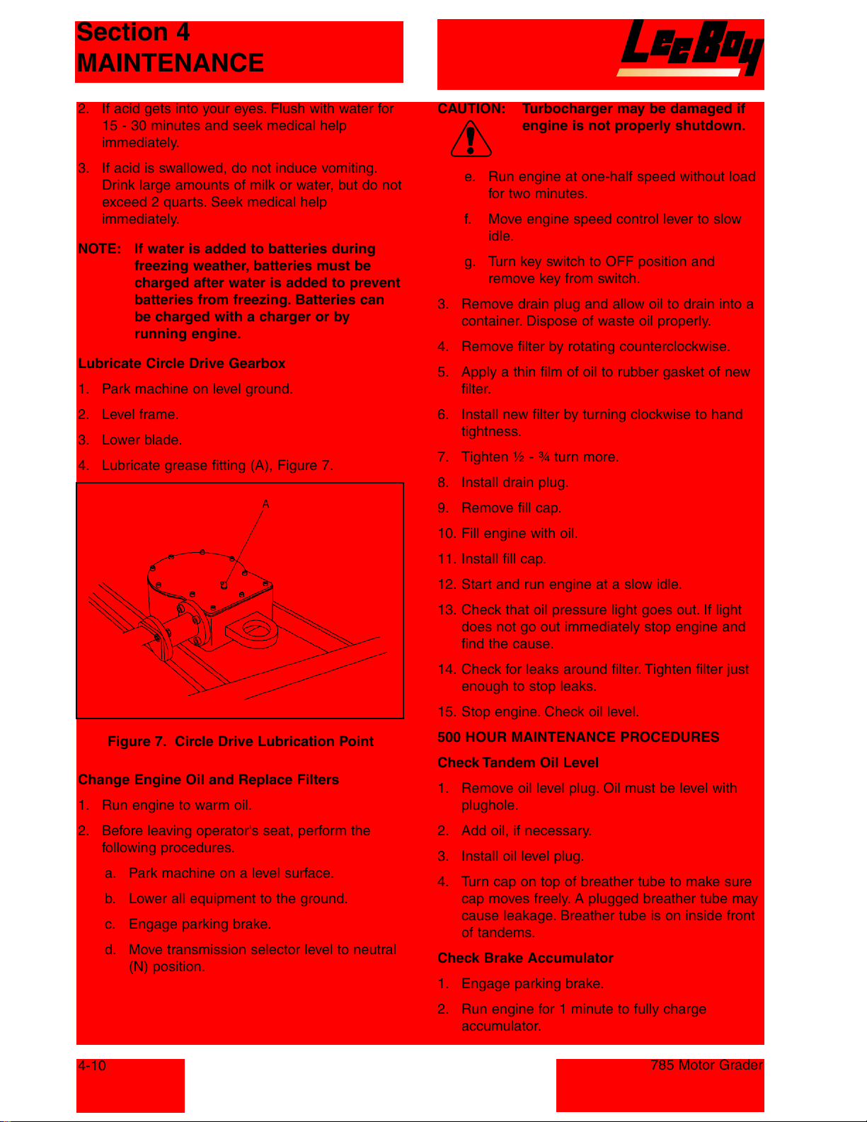
Section 4
MAINTENANCE
2. If acid gets into your eyes. Flush with water for
15 - 30 minutes and seek medical help
immediately.
3. If acid is swallowed, do not induce vomiting.
Drink large amounts of milk or water, but do not
exceed 2 quarts. Seek medical help
immediately.
NOTE: If water is added to batteries during
freezing weather, batteries must be
charged after water is added to prevent
batteries from freezing. Batteries can
be charged with a charger or by
running engine.
Lubricate Circle Drive Gearbox
1. Park machine on level ground.
2. Level frame.
3. Lower blade.
4. Lubricate grease fitting (A), Figure 7.
CAUTION: Turbocharger may be damaged if
engine is not properly shutdown.
e. Run engine at one-half speed without load
for two minutes.
f. Move engine speed control lever to slow
idle.
g. Turn key switch to OFF position and
remove key from switch.
3. Remove drain plug and allow oil to drain into a
container. Dispose of waste oil properly.
4. Remove filter by rotating counterclockwise.
5. Apply a thin film of oil to rubber gasket of new
filter.
6. Install new filter by turning clockwise to hand
tightness.
7. Tighten ½ - ¾ turn more.
8. Install drain plug.
9. Remove fill cap.
Figure 7. Circle Drive Lubrication Point
Change Engine Oil and Replace Filters
1. Run engine to warm oil.
2. Before leaving operator's seat, perform the
following procedures.
a. Park machine on a level surface.
b. Lower all equipment to the ground.
c. Engage parking brake.
d. Move transmission selector level to neutral
(N) position.
10. Fill engine with oil.
11. Install fill cap.
12. Start and run engine at a slow idle.
13. Check that oil pressure light goes out. If light
does not go out immediately stop engine and
find the cause.
14. Check for leaks around filter. Tighten filter just
enough to stop leaks.
15. Stop engine. Check oil level.
500 HOUR MAINTENANCE PROCEDURES
Check Tandem Oil Level
1. Remove oil level plug. Oil must be level with
plughole.
2. Add oil, if necessary.
3. Install oil level plug.
4. Turn cap on top of breather tube to make sure
cap moves freely. A plugged breather tube may
cause leakage. Breather tube is on inside front
of tandems.
Check Brake Accumulator
1. Engage parking brake.
4-10
2. Run engine for 1 minute to fully charge
accumulator.
785 Motor Grader
Courtesy of Machine.Market
Page 53
Section 4
MAINTENANCE
3. Stop engine.
4. Turn key to BULB CHECK position and release
to "arm" the monitor. Brake pressure indicator
must be off. Other indicator lights will be on and
stop engine indicator will flash.
5. Apply brake five times at 5 second intervals.
Brake pressure indicator must not come on
before three applications and pedal should feel
firm for five applications.
NOTE: If brake pressure indicator comes on
before three applications or pedal feels
"soft" before five applications: There is
a hydraulic leak in the brake system,
there is air in the brake system or the
nitrogen gas precharge in the
accumulator is too low.
CAUTION: Do not operate the machine until
the problem is resolved.
6. Continue to apply brakes until brake pressure
light is on. If pedal feels "soft" before brake
pressure light is on, do not operate the
machine until low brake pressure condition has
been corrected.
Replace Hydraulic Return Oil Filter
NOTE: Hydraulic return oil filter is a spin-on
type filter.
3. Install new filter.
4. Add oil.
5. Start engine and run at one-half speed for 2
minutes.
6. Stop engine.
7. Check for leaks around filter. Tighten filter only
enough to stop leaks.
8. Check oil level.
Replace Fuel Filter
NOTE: Fuel filter is a spin-on type filter.
1. Remove spin-on filter.
2. Clean mounting surface.
3. Install new filter.
4. Loosen bleed screw.
5. Operate primer lever until fuel flows from bleed
screw is free of bubbles.
1000 HOUR MAINTENANCE PROCEDURES
Engine Speed
1. Warm engine to normal operating temperature.
2. Connect a tachometer to check engine speed.
Slow Idle 900 +/-25 rpm
Fast Idle 2500 +/-25 rpm
If engine speeds need adjustment, see your
authorized dealer.
1. Remove spin-on filter.
2. Clean mounting surface.
3. Install new filter.
4. Add oil.
5. Start engine and run at one-half speed for 2
minutes.
6. Stop engine.
7. Check for leaks around filter. Tighten filter only
enough to stop leaks.
8. Check oil level.
Replace Transmission Oil Filter
NOTE: Transmission oil filter is a spin-on type
filter.
1. Remove spin-on filter.
2. Clean mounting surface.
785 Motor Grader
Clean, Pack, and Adjust Front Wheel Bearings
NOTE: If machine is operated in wet or muddy
conditions, clean and pack bearing as
necessary.
1. Remove the following parts, see Figure 8.
a. Hub cap (10)
b. Gasket (30)
c. Cotter pin (40) and castle nut (50)
d. Retainer Washer (60)
e. Bearing cone (70)
f. Wheel Hub (90)
g. Bearing cone (110)
h. Bearing cup (120)
i. Tandem axle seal (100)
4-11
Courtesy of Machine.Market
Page 54
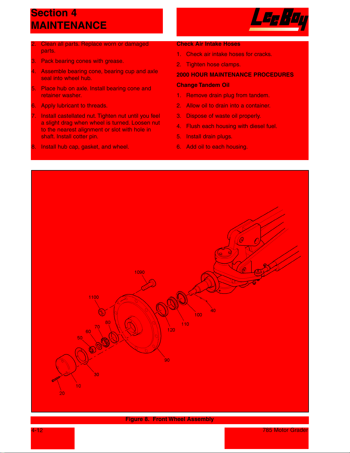
Section 4
MAINTENANCE
2. Clean all parts. Replace worn or damaged
parts.
3. Pack bearing cones with grease.
4. Assemble bearing cone, bearing cup and axle
seal into wheel hub.
5. Place hub on axle. Install bearing cone and
retainer washer.
6. Apply lubricant to threads.
7. Install castellated nut. Tighten nut until you feel
a slight drag when wheel is turned. Loosen nut
to the nearest alignment or slot with hole in
shaft. Install cotter pin.
8. Install hub cap, gasket, and wheel.
Check Air Intake Hoses
1. Check air intake hoses for cracks.
2. Tighten hose clamps.
2000 HOUR MAINTENANCE PROCEDURES
Change Tandem Oil
1. Remove drain plug from tandem.
2. Allow oil to drain into a container.
3. Dispose of waste oil properly.
4. Flush each housing with diesel fuel.
5. Install drain plugs.
6. Add oil to each housing.
4-12
Figure 8. Front Wheel Assembly
785 Motor Grader
Courtesy of Machine.Market
Page 55
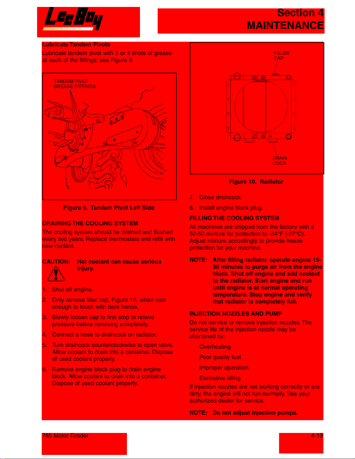
Lubricate Tandem Pivots
Lubricate tandem pivot with 3 or 4 shots of grease
at each of the fittings; see Figure 9.
Section 4
MAINTENANCE
Figure 10. Radiator
Figure 9. Tandem Pivot Left Side
DRAINING THE COOLING SYSTEM
The cooling system should be drained and flushed
every two years. Replace thermostats and refill with
new coolant.
CAUTION: Hot coolant can cause serious
injury.
1. Shut off engine.
2. Only remove filler cap, Figure 10, when cool
enough to touch with bare hands.
3. Slowly loosen cap to first stop to relieve
pressure before removing completely.
4. Connect a hose to draincock on radiator.
5. Turn draincock counterclockwise to open valve.
Allow coolant to drain into a container. Dispose
of used coolant properly.
6. Remove engine block plug to drain engine
block. Allow coolant to drain into a container.
Dispose of used coolant properly.
7. Close draincock.
8. Install engine block plug.
FILLING THE COOLING SYSTEM
All machines are shipped from the factory with a
50-50 mixture for protection to -34°F (-37°C).
Adjust mixture accordingly to provide freeze
protection for your machine.
NOTE: After filling radiator, operate engine 15-
30 minutes to purge air from the engine
block. Shut off engine and add coolant
to the radiator. Start engine and run
until engine is at normal operating
temperature. Stop engine and verify
that radiator is completely full.
INJECTION NOZZLES AND PUMP
Do not service or remove injection nozzles. The
service life of the injection nozzle may be
shortened by:
Overheating
Poor quality fuel
Improper operation
Excessive idling
If injection nozzles are not working correctly or are
dirty, the engine will not run normally. See your
authorized dealer for service.
785 Motor Grader
NOTE: Do not adjust injection pumps.
4-13
Courtesy of Machine.Market
Page 56
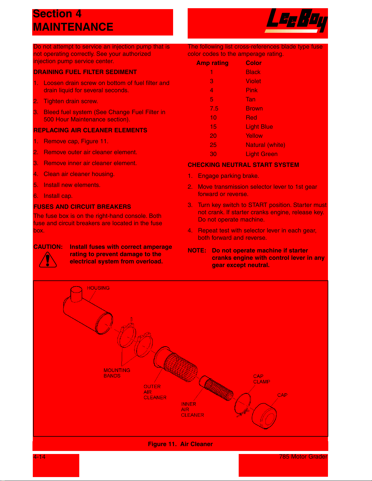
Section 4
MAINTENANCE
Do not attempt to service an injection pump that is
not operating correctly. See your authorized
injection pump service center.
DRAINING FUEL FILTER SEDIMENT
1. Loosen drain screw on bottom of fuel filter and
drain liquid for several seconds.
2. Tighten drain screw.
3. Bleed fuel system (See Change Fuel Filter in
500 Hour Maintenance section).
REPLACING AIR CLEANER ELEMENTS
1. Remove cap, Figure 11.
2. Remove outer air cleaner element.
3. Remove inner air cleaner element.
4. Clean air cleaner housing.
5. Install new elements.
6. Install cap.
FUSES AND CIRCUIT BREAKERS
The fuse box is on the right-hand console. Both
fuse and circuit breakers are located in the fuse
box.
CAUTION: Install fuses with correct amperage
rating to prevent damage to the
electrical system from overload.
The following list cross-references blade type fuse
color codes to the amperage rating.
Amp rating Color
1 Black
3 Violet
4 Pink
5Tan
7.5 Brown
10 Red
15 Light Blue
20 Yellow
25 Natural (white)
30 Light Green
CHECKING NEUTRAL START SYSTEM
1. Engage parking brake.
2. Move transmission selector lever to 1st gear
forward or reverse.
3. Turn key switch to START position. Starter must
not crank. If starter cranks engine, release key.
Do not operate machine.
4. Repeat test with selector lever in each gear,
both forward and reverse.
NOTE: Do not operate machine if starter
cranks engine with control lever in any
gear except neutral.
4-14
Figure 11. Air Cleaner
785 Motor Grader
Courtesy of Machine.Market
Page 57
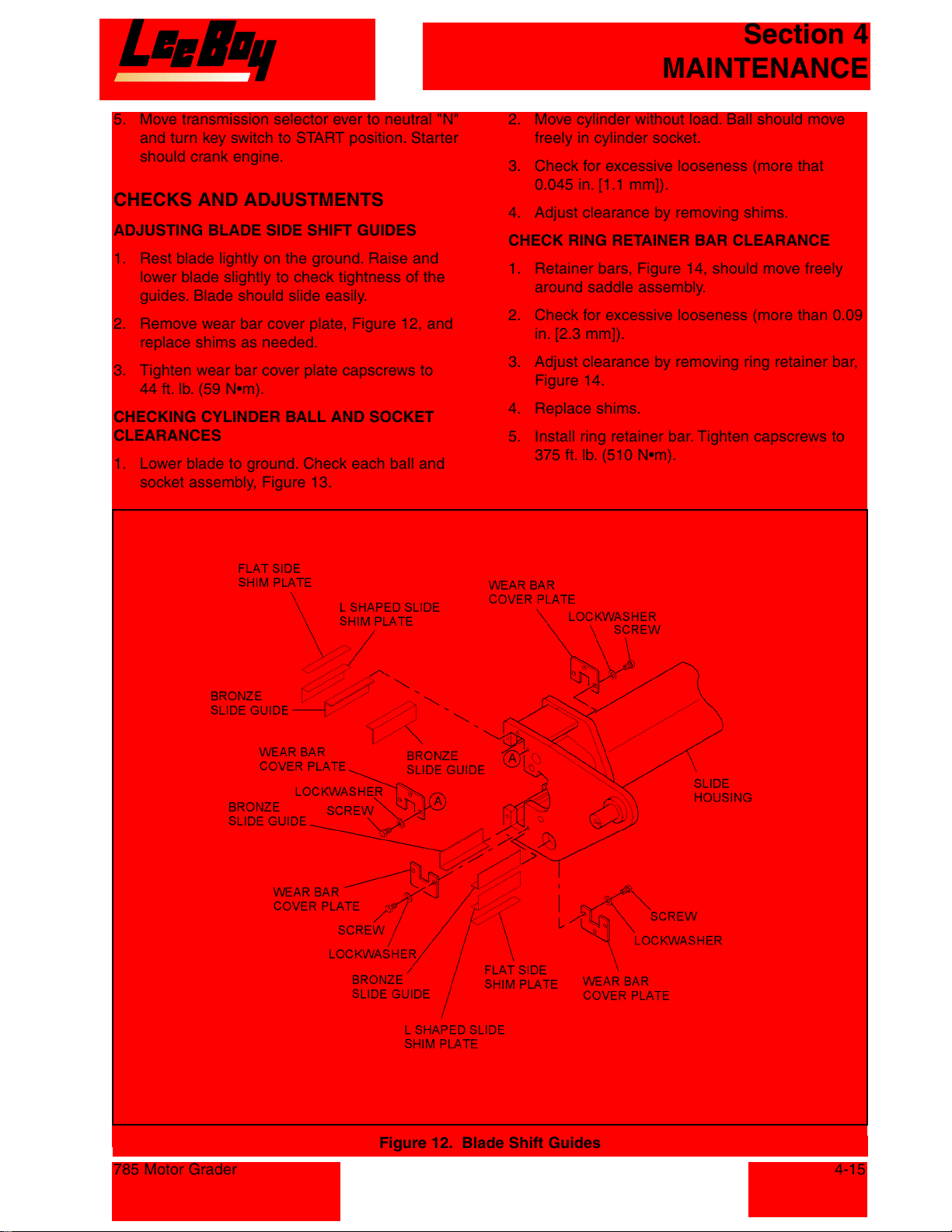
Section 4
MAINTENANCE
5. Move transmission selector ever to neutral "N"
and turn key switch to START position. Starter
should crank engine.
CHECKS AND ADJUSTMENTS
ADJUSTING BLADE SIDE SHIFT GUIDES
1. Rest blade lightly on the ground. Raise and
lower blade slightly to check tightness of the
guides. Blade should slide easily.
2. Remove wear bar cover plate, Figure 12, and
replace shims as needed.
3. Tighten wear bar cover plate capscrews to
44 ft. lb. (59 N•m).
CHECKING CYLINDER BALL AND SOCKET
CLEARANCES
1. Lower blade to ground. Check each ball and
socket assembly, Figure 13.
2. Move cylinder without load. Ball should move
freely in cylinder socket.
3. Check for excessive looseness (more that
0.045 in. [1.1 mm]).
4. Adjust clearance by removing shims.
CHECK RING RETAINER BAR CLEARANCE
1. Retainer bars, Figure 14, should move freely
around saddle assembly.
2. Check for excessive looseness (more than 0.09
in. [2.3 mm]).
3. Adjust clearance by removing ring retainer bar,
Figure 14.
4. Replace shims.
5. Install ring retainer bar. Tighten capscrews to
375 ft. lb. (510 N•m).
785 Motor Grader
Figure 12. Blade Shift Guides
4-15
Courtesy of Machine.Market
Page 58
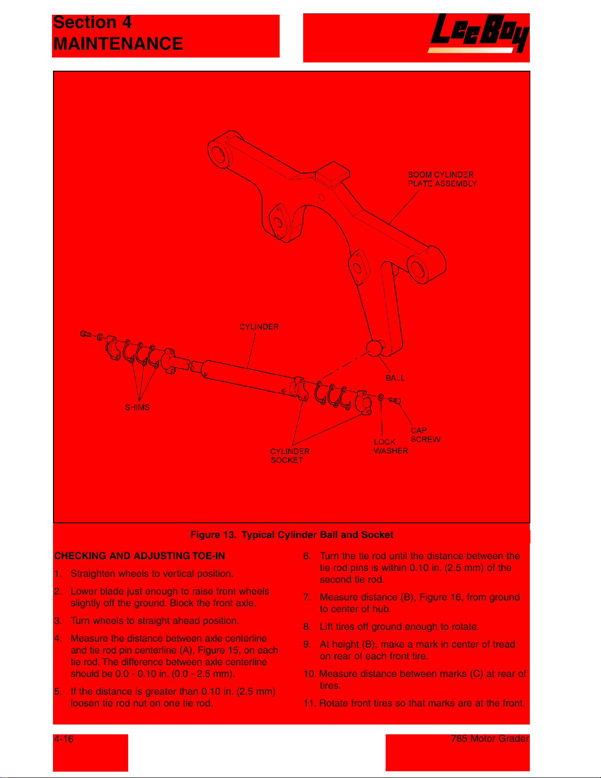
Section 4
MAINTENANCE
Figure 13. Typical Cylinder Ball and Socket
CHECKING AND ADJUSTING TOE-IN
1. Straighten wheels to vertical position.
2. Lower blade just enough to raise front wheels
slightly off the ground. Block the front axle.
3. Turn wheels to straight ahead position.
4. Measure the distance between axle centerline
and tie rod pin centerline (A), Figure 15, on each
tie rod. The difference between axle centerline
should be 0.0 - 0.10 in. (0.0 - 2.5 mm).
5. If the distance is greater than 0.10 in. (2.5 mm)
loosen tie rod nut on one tie rod.
4-16
6. Turn the tie rod until the distance between the
tie rod pins is within 0.10 in. (2.5 mm) of the
second tie rod.
7. Measure distance (B), Figure 16, from ground
to center of hub.
8. Lift tires off ground enough to rotate.
9. At height (B), make a mark in center of tread
on rear of each front tire.
10. Measure distance between marks (C) at rear of
tires.
11. Rotate front tires so that marks are at the front.
785 Motor Grader
Courtesy of Machine.Market
Page 59
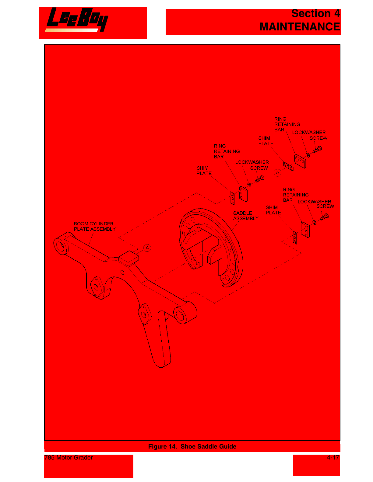
Section 4
MAINTENANCE
785 Motor Grader
Figure 14. Shoe Saddle Guide
4-17
Courtesy of Machine.Market
Page 60
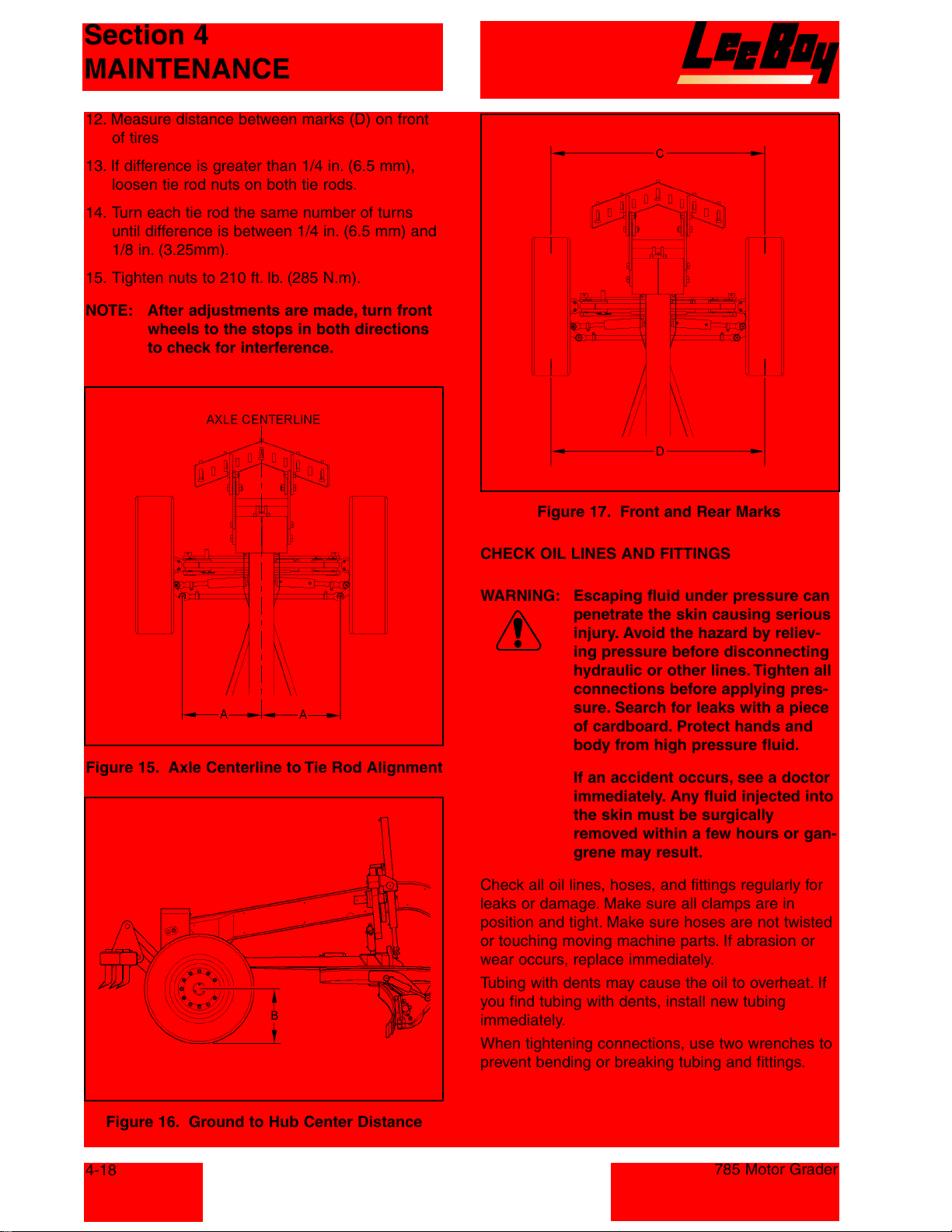
Section 4
MAINTENANCE
12. Measure distance between marks (D) on front
of tires
13. If difference is greater than 1/4 in. (6.5 mm),
loosen tie rod nuts on both tie rods.
14. Turn each tie rod the same number of turns
until difference is between 1/4 in. (6.5 mm) and
1/8 in. (3.25mm).
15. Tighten nuts to 210 ft. lb. (285 N.m).
NOTE: After adjustments are made, turn front
wheels to the stops in both directions
to check for interference.
Figure 15. Axle Centerline to Tie Rod Alignment
Figure 17. Front and Rear Marks
CHECK OIL LINES AND FITTINGS
WARNING: Escaping fluid under pressure can
penetrate the skin causing serious
injury. Avoid the hazard by reliev-
ing pressure before disconnecting
hydraulic or other lines. Tighten all
connections before applying pres-
sure. Search for leaks with a piece
of cardboard. Protect hands and
body from high pressure fluid.
If an accident occurs, see a doctor
immediately. Any fluid injected into
the skin must be surgically
removed within a few hours or gan-
grene may result.
Check all oil lines, hoses, and fittings regularly for
leaks or damage. Make sure all clamps are in
position and tight. Make sure hoses are not twisted
or touching moving machine parts. If abrasion or
wear occurs, replace immediately.
Tubing with dents may cause the oil to overheat. If
you find tubing with dents, install new tubing
immediately.
When tightening connections, use two wrenches to
prevent bending or breaking tubing and fittings.
Figure 16. Ground to Hub Center Distance
4-18
785 Motor Grader
Courtesy of Machine.Market
Page 61
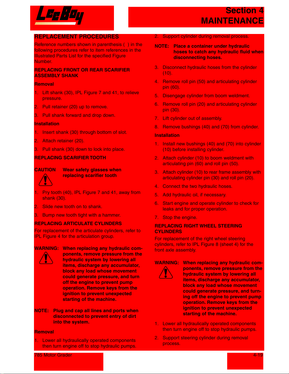
Section 4
MAINTENANCE
REPLACEMENT PROCEDURES
Reference numbers shown in parenthesis ( ) in the
following procedures refer to item references in the
Illustrated Parts List for the specified Figure
Number.
REPLACING FRONT OR REAR SCARIFIER
ASSEMBLY SHANK
Removal
1. Lift shank (30), IPL Figure 7 and 41, to relieve
pressure.
2. Pull retainer (20) up to remove.
3. Pull shank forward and drop down.
Installation
1. Insert shank (30) through bottom of slot.
2. Attach retainer (20).
3. Pull shank (30) down to lock into place.
REPLACING SCARIFIER TOOTH
CAUTION Wear safety glasses when
replacing scarifier tooth
2. Support cylinder during removal process.
NOTE: Place a container under hydraulic
hoses to catch any hydraulic fluid when
disconnecting hoses.
3. Disconnect hydraulic hoses from the cylinder
(10).
4. Remove roll pin (50) and articulating cylinder
pin (60).
5. Disengage cylinder from boom weldment.
6. Remove roll pin (20) and articulating cylinder
pin (30).
7. Lift cylinder out of assembly.
8. Remove bushings (40) and (70) from cylinder.
Installation
1. Install new bushings (40) and (70) into cylinder
(10) before installing cylinder.
2. Attach cylinder (10) to boom weldment with
articulating pin (60) and roll pin (50).
3. Attach cylinder (10) to rear frame assembly with
articulating cylinder pin (30) and roll pin (20).
1. Pry tooth (40), IPL Figure 7 and 41, away from
shank (30).
2. Slide new tooth on to shank.
3. Bump new tooth tight with a hammer.
REPLACING ARTICULATE CYLINDERS
For replacement of the articulate cylinders, refer to
IPL Figure 4 for the articulation group.
WARNING: When replacing any hydraulic com-
ponents, remove pressure from the
hydraulic system by lowering all
items, discharge any accumulator,
block any load whose movement
could generate pressure, and turn
off the engine to prevent pump
operation. Remove keys from the
ignition to prevent unexpected
starting of the machine.
NOTE: Plug and cap all lines and ports when
disconnected to prevent entry of dirt
into the system.
Removal
1. Lower all hydraulically operated components
then turn engine off to stop hydraulic pumps.
4. Connect the two hydraulic hoses.
5. Add hydraulic oil, if necessary.
6. Start engine and operate cylinder to check for
leaks and for proper operation.
7. Stop the engine.
REPLACING RIGHT WHEEL STEERING
CYLINDERS
For replacement of the right wheel steering
cylinders, refer to IPL Figure 8 (sheet 4) for the
front axle assembly.
WARNING: When replacing any hydraulic com-
ponents, remove pressure from the
hydraulic system by lowering all
items, discharge any accumulator,
block any load whose movement
could generate pressure, and turn-
ing off the engine to prevent pump
operation. Remove keys from the
ignition to prevent unexpected
starting of the machine.
1. Lower all hydraulically operated components
then turn engine off to stop hydraulic pumps.
2. Support steering cylinder during removal
process.
785 Motor Grader
4-19
Courtesy of Machine.Market
Page 62
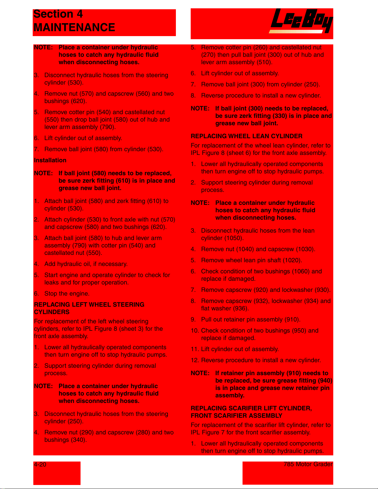
Section 4
MAINTENANCE
NOTE: Place a container under hydraulic
hoses to catch any hydraulic fluid
when disconnecting hoses.
3. Disconnect hydraulic hoses from the steering
cylinder (530).
4. Remove nut (570) and capscrew (560) and two
bushings (620).
5. Remove cotter pin (540) and castellated nut
(550) then drop ball joint (580) out of hub and
lever arm assembly (790).
6. Lift cylinder out of assembly.
7. Remove ball joint (580) from cylinder (530).
Installation
NOTE: If ball joint (580) needs to be replaced,
be sure zerk fitting (610) is in place and
grease new ball joint.
1. Attach ball joint (580) and zerk fitting (610) to
cylinder (530).
2. Attach cylinder (530) to front axle with nut (570)
and capscrew (580) and two bushings (620).
3. Attach ball joint (580) to hub and lever arm
assembly (790) with cotter pin (540) and
castellated nut (550).
4. Add hydraulic oil, if necessary.
5. Start engine and operate cylinder to check for
leaks and for proper operation.
6. Stop the engine.
REPLACING LEFT WHEEL STEERING
CYLINDERS
For replacement of the left wheel steering
cylinders, refer to IPL Figure 8 (sheet 3) for the
front axle assembly.
1. Lower all hydraulically operated components
then turn engine off to stop hydraulic pumps.
2. Support steering cylinder during removal
process.
NOTE: Place a container under hydraulic
hoses to catch any hydraulic fluid
when disconnecting hoses.
3. Disconnect hydraulic hoses from the steering
cylinder (250).
4. Remove nut (290) and capscrew (280) and two
bushings (340).
5. Remove cotter pin (260) and castellated nut
(270) then pull ball joint (300) out of hub and
lever arm assembly (510).
6. Lift cylinder out of assembly.
7. Remove ball joint (300) from cylinder (250).
8. Reverse procedure to install a new cylinder.
NOTE: If ball joint (300) needs to be replaced,
be sure zerk fitting (330) is in place and
grease new ball joint.
REPLACING WHEEL LEAN CYLINDER
For replacement of the wheel lean cylinder, refer to
IPL Figure 8 (sheet 6) for the front axle assembly.
1. Lower all hydraulically operated components
then turn engine off to stop hydraulic pumps.
2. Support steering cylinder during removal
process.
NOTE: Place a container under hydraulic
hoses to catch any hydraulic fluid
when disconnecting hoses.
3. Disconnect hydraulic hoses from the lean
cylinder (1050).
4. Remove nut (1040) and capscrew (1030).
5. Remove wheel lean pin shaft (1020).
6. Check condition of two bushings (1060) and
replace if damaged.
7. Remove capscrew (920) and lockwasher (930).
8. Remove capscrew (932), lockwasher (934) and
flat washer (936).
9. Pull out retainer pin assembly (910).
10. Check condition of two bushings (950) and
replace if damaged.
11. Lift cylinder out of assembly.
12. Reverse procedure to install a new cylinder.
NOTE: If retainer pin assembly (910) needs to
be replaced, be sure grease fitting (940)
is in place and grease new retainer pin
assembly.
REPLACING SCARIFIER LIFT CYLINDER,
FRONT SCARIFIER ASSEMBLY
For replacement of the scarifier lift cylinder, refer to
IPL Figure 7 for the front scarifier assembly.
1. Lower all hydraulically operated components
then turn engine off to stop hydraulic pumps.
4-20
785 Motor Grader
Courtesy of Machine.Market
Page 63
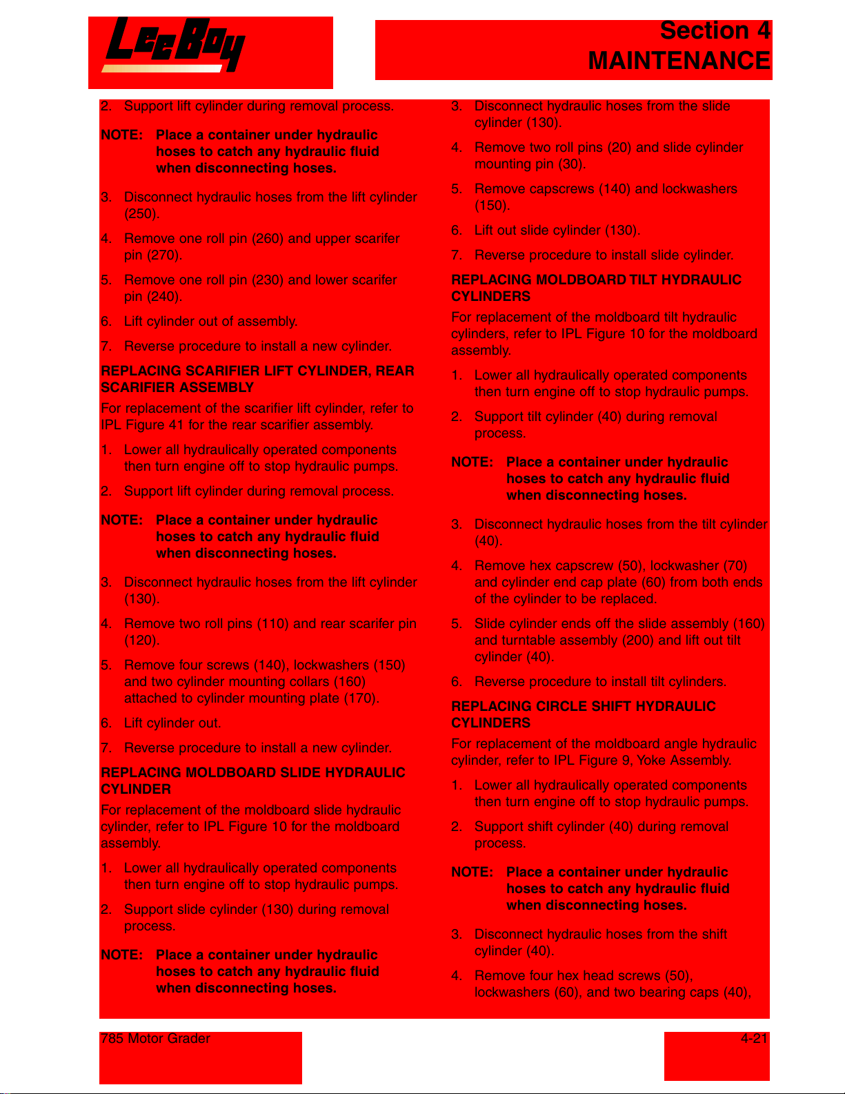
Section 4
MAINTENANCE
2. Support lift cylinder during removal process.
NOTE: Place a container under hydraulic
hoses to catch any hydraulic fluid
when disconnecting hoses.
3. Disconnect hydraulic hoses from the lift cylinder
(250).
4. Remove one roll pin (260) and upper scarifer
pin (270).
5. Remove one roll pin (230) and lower scarifer
pin (240).
6. Lift cylinder out of assembly.
7. Reverse procedure to install a new cylinder.
REPLACING SCARIFIER LIFT CYLINDER, REAR
SCARIFIER ASSEMBLY
For replacement of the scarifier lift cylinder, refer to
IPL Figure 41 for the rear scarifier assembly.
1. Lower all hydraulically operated components
then turn engine off to stop hydraulic pumps.
2. Support lift cylinder during removal process.
3. Disconnect hydraulic hoses from the slide
cylinder (130).
4. Remove two roll pins (20) and slide cylinder
mounting pin (30).
5. Remove capscrews (140) and lockwashers
(150).
6. Lift out slide cylinder (130).
7. Reverse procedure to install slide cylinder.
REPLACING MOLDBOARD TILT HYDRAULIC
CYLINDERS
For replacement of the moldboard tilt hydraulic
cylinders, refer to IPL Figure 10 for the moldboard
assembly.
1. Lower all hydraulically operated components
then turn engine off to stop hydraulic pumps.
2. Support tilt cylinder (40) during removal
process.
NOTE: Place a container under hydraulic
hoses to catch any hydraulic fluid
when disconnecting hoses.
NOTE: Place a container under hydraulic
hoses to catch any hydraulic fluid
when disconnecting hoses.
3. Disconnect hydraulic hoses from the lift cylinder
(130).
4. Remove two roll pins (110) and rear scarifer pin
(120).
5. Remove four screws (140), lockwashers (150)
and two cylinder mounting collars (160)
attached to cylinder mounting plate (170).
6. Lift cylinder out.
7. Reverse procedure to install a new cylinder.
REPLACING MOLDBOARD SLIDE HYDRAULIC
CYLINDER
For replacement of the moldboard slide hydraulic
cylinder, refer to IPL Figure 10 for the moldboard
assembly.
1. Lower all hydraulically operated components
then turn engine off to stop hydraulic pumps.
2. Support slide cylinder (130) during removal
process.
NOTE: Place a container under hydraulic
hoses to catch any hydraulic fluid
when disconnecting hoses.
3. Disconnect hydraulic hoses from the tilt cylinder
(40).
4. Remove hex capscrew (50), lockwasher (70)
and cylinder end cap plate (60) from both ends
of the cylinder to be replaced.
5. Slide cylinder ends off the slide assembly (160)
and turntable assembly (200) and lift out tilt
cylinder (40).
6. Reverse procedure to install tilt cylinders.
REPLACING CIRCLE SHIFT HYDRAULIC
CYLINDERS
For replacement of the moldboard angle hydraulic
cylinder, refer to IPL Figure 9, Yoke Assembly.
1. Lower all hydraulically operated components
then turn engine off to stop hydraulic pumps.
2. Support shift cylinder (40) during removal
process.
NOTE: Place a container under hydraulic
hoses to catch any hydraulic fluid
when disconnecting hoses.
3. Disconnect hydraulic hoses from the shift
cylinder (40).
4. Remove four hex head screws (50),
lockwashers (60), and two bearing caps (40),
785 Motor Grader
4-21
Courtesy of Machine.Market
Page 64
Section 4
MAINTENANCE
5. Remove cylinder from plate assembly (270)
and from moldboard assembly (10), IPL Figure
2, and lift out shift cylinder (40), IPL Figure 9.
6. Reverse procedure to install shift cylinders and
torque capscrews (50) to 210 in. lb. (23.7 N•m).
REPLACING MOLDBOARD LIFT HYDRAULIC
CYLINDERS
For replacement of the moldboard lift hydraulic
cylinders, refer to IPL Figure 9, Yoke Assembly.
Removal
1. Lower all hydraulically operated components
then turn engine off to stop hydraulic pumps.
2. Support lift cylinder (220) to be removed during
removal process.
NOTE: Place a container under hydraulic
hoses to catch any hydraulic fluid
when disconnecting hoses.
3. Disconnect hydraulic hoses from the lift cylinder
(220).
4. Remove two hex capscrews (230), lockwashers
(240) and the bearing cap (220), disconnecting
cylinder (220) from moldboard assembly (10),
IPL Figure 2.
5. Remove two capscrews (150), IPL Figure 9,
lockwashers (160), and each cylinder bottom
clamp plate (140).
6. Remove cylinder end cap (180), steel bushing
(190), drawbar bushing (200), and oil seal (210).
Installation
1. Install grease fittings (250) into cylinder end
caps (180).
2. Install new oil seals (210), drawbar bushings
(200), steel bushings (190), and cylinder end
caps (180).
3. Position cylinders (220) in cylinder clamps
(170).
4. Attach each cylinder bottom clamp plate (140)
with two capscrews (150) and lockwashers
(160).
5. Torque capscrews (150) to 105 in. lb. (11.9 N•m).
6. Attach bearing cap (220) with hex capscrew
(230) and lockwasher (240) to moldboard
assembly (10), IPL Figure 2.
7. Torque capscrews (230), IPL Figure 9, to 210 in.
lb. (23.7 N•m).
NOTE: If hydraulic fittings have been removed
from the cylinder, be sure that the
fitting with the orifice is attached at the
rod end.
REPLACING MOLDBOARD END BITS
For replacement of the moldboard end bits, refer to
IPL Figure 11 for the moldboard assembly.
1. Remove the four nuts (60) and plow bolts (50)
securing each end bit (40) to moldboard
weldment (70) and remove end bit (40).
2. Reverse procedures to install a new end bit.
REPLACING MOLDBOARD CUTTING EDGE
For replacement of the moldboard cutting edge,
refer to IPL Figure 11 for the moldboard assembly.
1. Raise moldboard so that cutting edges (10) are
off ground.
2. Remove the eight nuts (30) and plow bolts
(20) securing each cutting edge (10) to
moldboard weldment (70) and remove each
cutting edge (10).
3. Reverse procedures to install a new cutting edge.
REPLACING HYDRAULIC RESERVOIR
STRAINERS
For replacement of the hydraulic reservoir strainers
refer to IPL Figure 37.
Hydraulic Oil Suction Strainer and Hydraulic Oil
Strainer Filter
WARNING: Hydraulic oil is extremely hot
after use. Allow oil to cool before
servicing.
1. Lower all hydraulically operated components.
Turn engine off to stop hydraulic pumps.
2. Place a container with enough capacity to hold
the hydraulic fluid from the hydraulic tank.
3. Drain the hydraulic tank and discard the oil in
accordance with regulations.
4. Disconnect suction line from strainer.
5. Remove the oil suction strainer (20) or oil
strainer filter (30) as applicable.
6. Install new components.
7. Reconnect the suction line to strainer.
8. Refill the hydraulic tank with new hydraulic fluid.
9. Check system operation.
4-22
785 Motor Grader
Courtesy of Machine.Market
Page 65
Section 4
MAINTENANCE
Strainer and Gasket Kit
WARNING: Hydraulic oil is extremely hot
after use. Allow oil to cool before
servicing.
1. Remove cap (40).
2. Remove six screws (60).
3. Remove filler neck (50).
4. Remove strainer and gasket (70).
5. Install new strainer and gasket (70) and align
the six screw holes of the components.
6. Install filler neck (50) and align screw holes.
7. Attach filler neck (50) and strainer and gasket
kit (70) with the six screws (60).
8. Check hydraulic oil level and add oil if required.
9. Install cap (40).
REPLACING EXHAUST SYSTEM
For replacement of the muffler, refer to IPL
Figure 33.
4. Support radiator during removal process.
5. Remove nuts (70), lockwashers (80), and
screws (60) attaching radiator-mounting pad
(50) to radiator support plate (90).
6. Lift radiator (10) off of mounting surface.
7. Remove screw (20), nut (30), and lockwasher
(40) attaching radiator-mounting pad (50) to
radiator.
NOTE: Check radiator mounting pads (50) for wear
or damage and replace if necessary.
8. Install a new radiator by reversing procedure.
9. Check for proper centering of the fan in the
shroud. Fan should be 2/3 in shroud for proper
air flow.
10. After reconnecting hoses, add coolant,
hydraulic fluid and transmission fluid as
needed. Add coolant to overflow tank if
necessary.
REPLACING VALVE BANK
Refer to IPL Figure 24 to replace a valve in the
valve group.
WARNING: Allow engine to cool down before
performing any service.
1. Support muffler (150) then loosen clamp (160)
attaching muffler to engine assembly (170).
2. Remove muffler (150) from grader.
3. Install new muffler by reversing procedure.
REPLACING RADIATOR ASSEMBLY
For replacement of the radiator, refer to IPL
Figure 33.
WARNING: Allow engine to cool down before
performing any service.
NOTE: Remove hood and grill to access
radiator.
1. Drain radiator coolant into a container large
enough the hold all radiator coolant.
2. Disconnect the transmission fluid lines and plug
lines. Allow transmission fluid in radiator to
drain into a container.
3. Disconnect the hydraulic fluid lines and plug
lines. Allow hydraulic fluid in radiator to drain
into a container.
785 Motor Grader
WARNING: When replacing any hydraulic com-
ponents, remove pressure from the
hydraulic system by lowering all
items, discharge any accumulator,
block any load whose movement
could generate pressure, and turn-
ing off the engine to prevent pump
operation. Remove keys from the
ignition to prevent unexpected
starting of the machine.
1. Lower all hydraulically operated components
then turn engine off to stop hydraulic pumps.
NOTE: Place a container under hydraulic
hoses to catch any hydraulic fluid
when disconnecting hoses.
2. Disconnect all hydraulic hoses from the valves.
3. Remove valve assembly and place on a clean
table for service.
4. Disconnect the ball stud heim joint (150 or 170),
as applicable, from the valve mount shaft (190).
5. Remove two nuts (100) and slide capscrew (90)
out far enough to clear the valve that is to be
replaced.
6. Slide the defective valve out of the valve
assembly.
4-23
Courtesy of Machine.Market
Page 66
Section 4
MAINTENANCE
7. Reverse procedure when installing a new valve.
8. Torque nuts (100) and capscrews (90) to 49 ft.
lb. (67 N•m).
REPLACING WINDSHIELD WIPER ASSEMBLY
The motor assembly (220) for the windshield wiper
is attached at the center of the windshield. Refer to
IPL Figure 17 to replace the motor assembly.
1. Remove wiper motor cover (215).
2. Disconnect electrical wires from wiper motor
(220).
3. Remove the wiper arm retaining nut (200), flat
washer (210), and wiper arm (190).
4. Remove self-locking nut (240), flat washer
(250) inside cab.
5. Remove screw (230) and flat washer (250)
outside cab.
6. Remove wiper motor (220).
7. Reverse procedure to install a new wiper motor
(220).
2. Secure the tire to the axle with the 12 nuts
(120) and studs (110). Be sure flat side of nut is
toward tire rim.
3. Using a torque wrench, torque the nuts in a
star pattern to even the tension on the wheel as
the nuts are tightened. Torque nuts to 460 ft. lb.
(628 N•m).
4. Remove the wooden bracing from under the
frame and lower to the ground.
5. Check tire pressure. Pressure should be 35 psi
(241 kPa) (2.45 bar).
Rear Wheel
For replacement of the rear tire and wheel, refer to
IPL Figure 4.
Removal
1. Place wooden blocks in front of and in back of
the front wheels.
2. Jack up the rear end of the grader, so that the
wheel that is to be removed is just touching the
ground.
REPLACING WHEEL AND TIRE
Front Wheel
For replacement of the front tire and wheel, refer to
IPL Figure 1.
Removal
1. Place wooden blocks in front of and in back of
the rear wheels.
2. Jack up the front end of the grader, under the
wheel that is to be removed so it is just
touching the ground.
3. Place wooden bracing under the frame in the
event the jack slips.
4. Remove the 12 nuts (120) securing the front
wheel (100 or -130) to the axle, then remove
wheel.
Installation
NOTE: Be sure tires are mounted on the rim
with proper tread orientation as shown
in the IPL.
1. Slide the front wheel (100 or -130) onto the
axle with the tire oriented as shown in the IPL.
3. Place wooden bracing under the frame in the
event the jack slips.
4. Remove the 12 nuts (230) securing the rear
wheel (210 or -240) to the axle, then remove
wheel.
Installation
NOTE: Be sure tires are mounted on the rim
with proper tread orientation as shown
in the IPL.
1. Slide the rear wheel (210 or -240) onto the axle
with the tire oriented as shown in the IPL.
2. Secure the tire to the axle with the 12 nuts
(230). Be sure flat side of nut is toward tire rim.
3. Using a torque wrench, torque the nuts in a
star pattern to even the tension on the wheel as
the nuts are tightened. Torque nuts to 460 ft. lb.
(624 N•m).
4. Remove the wooden bracing from under the
frame and lower to the ground.
5. Check tire pressure. Pressure should be 35 psi
(241 kPa) (2.45 bar).
4-24
785 Motor Grader
Courtesy of Machine.Market
Page 67
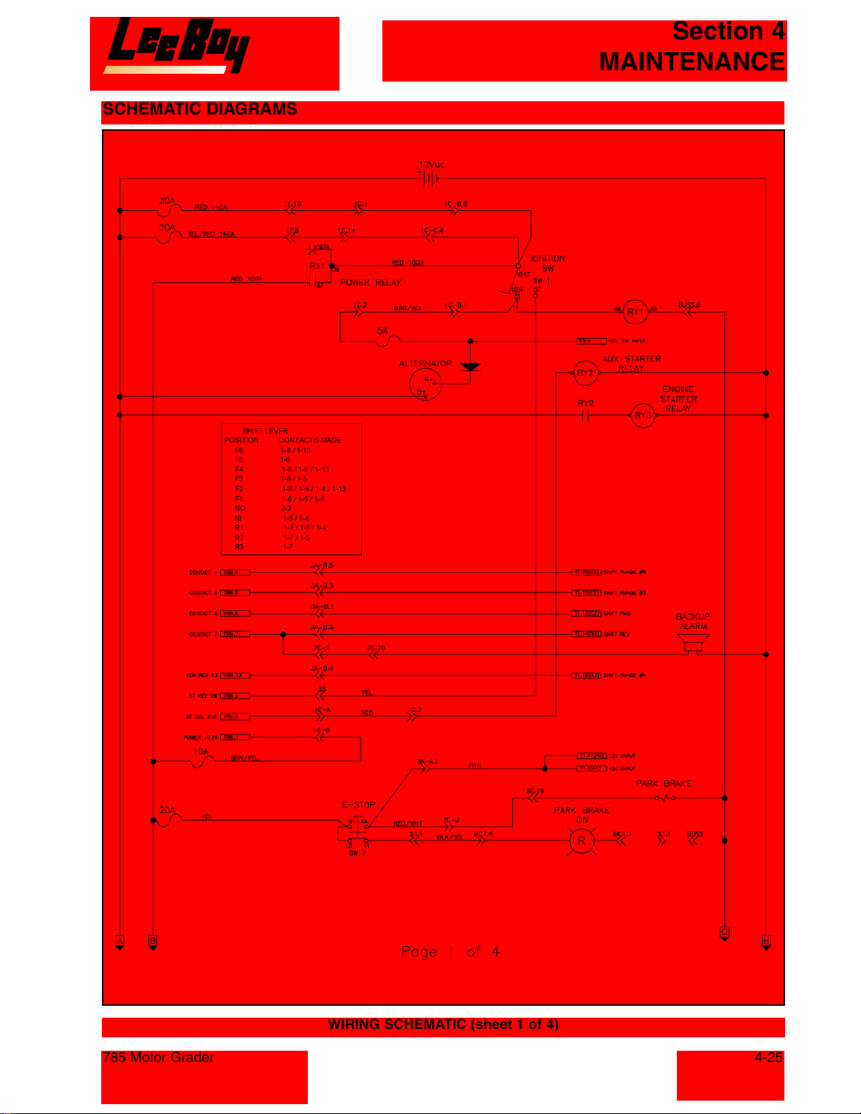
SCHEMATIC DIAGRAMS
Section 4
MAINTENANCE
785 Motor Grader
WIRING SCHEMATIC (sheet 1 of 4)
4-25
Courtesy of Machine.Market
Page 68
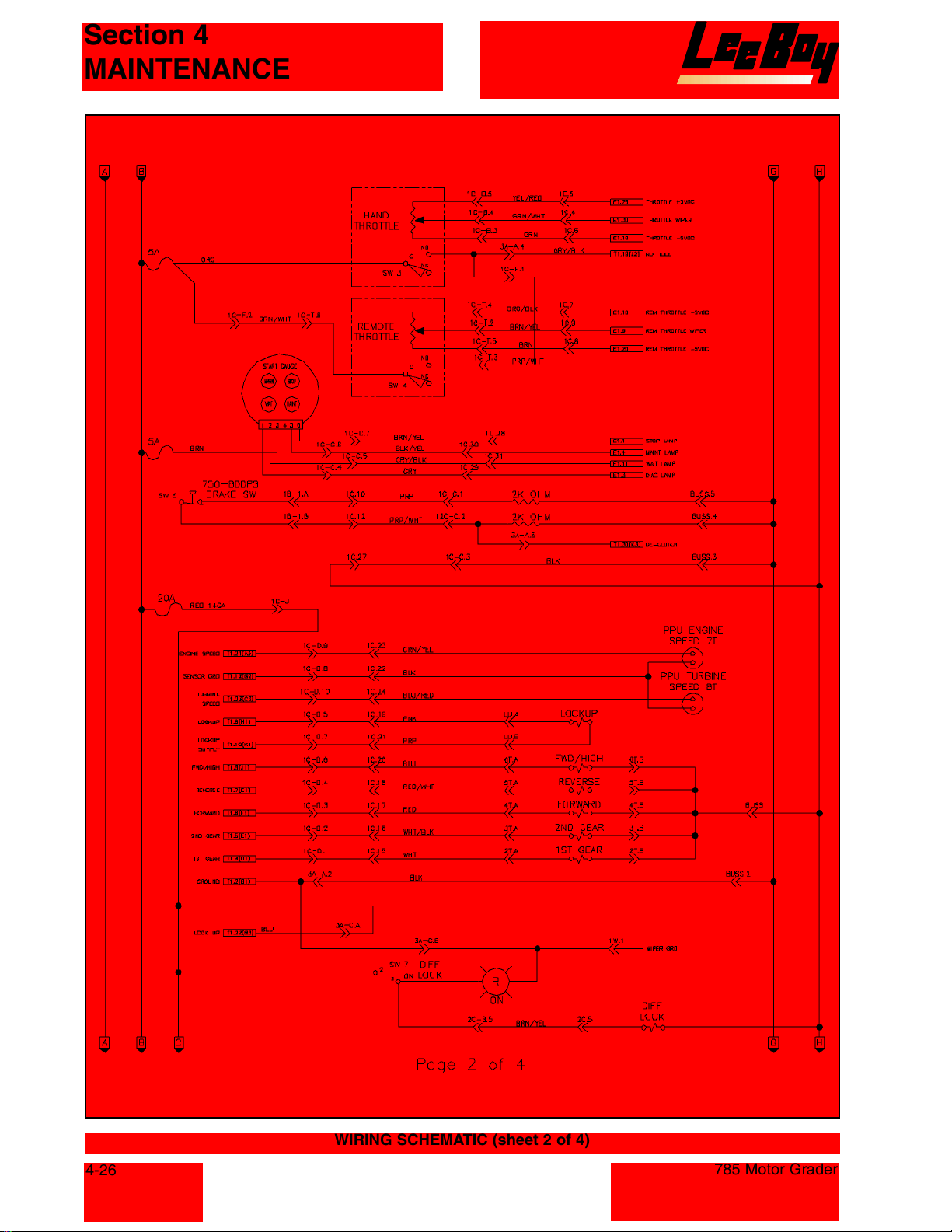
Section 4
MAINTENANCE
4-26
WIRING SCHEMATIC (sheet 2 of 4)
785 Motor Grader
Courtesy of Machine.Market
Page 69
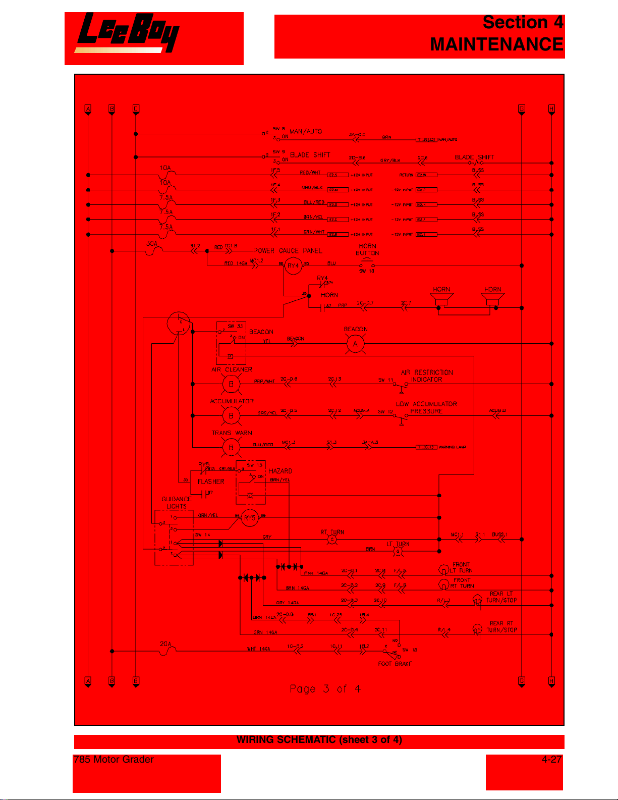
Section 4
MAINTENANCE
785 Motor Grader
WIRING SCHEMATIC (sheet 3 of 4)
4-27
Courtesy of Machine.Market
Page 70
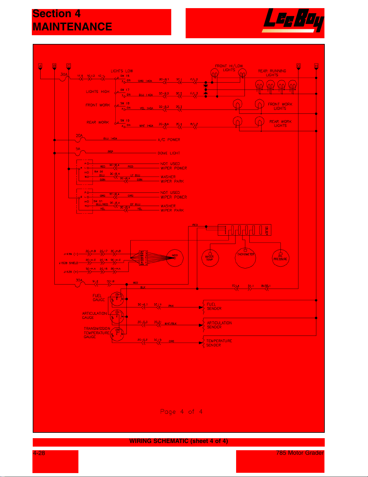
Section 4
MAINTENANCE
4-28
WIRING SCHEMATIC (sheet 4 of 4)
785 Motor Grader
Courtesy of Machine.Market
Page 71
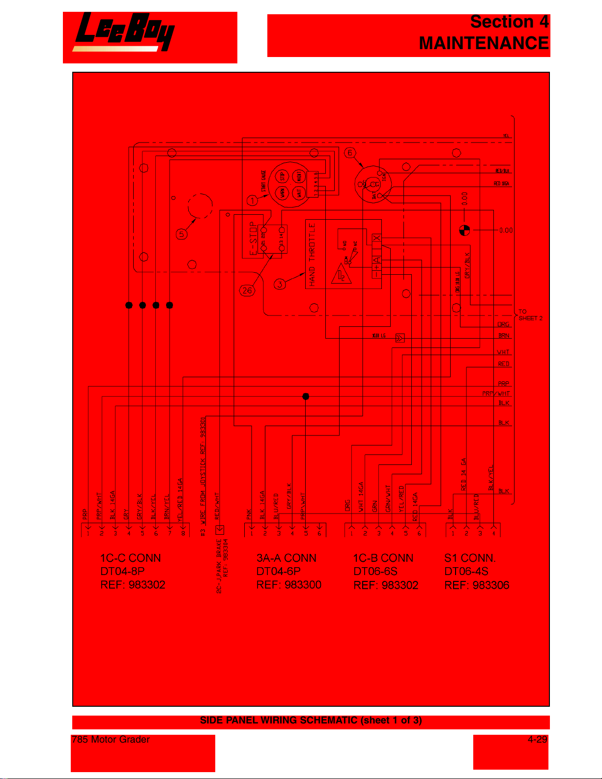
Section 4
MAINTENANCE
785 Motor Grader
SIDE PANEL WIRING SCHEMATIC (sheet 1 of 3)
4-29
Courtesy of Machine.Market
Page 72
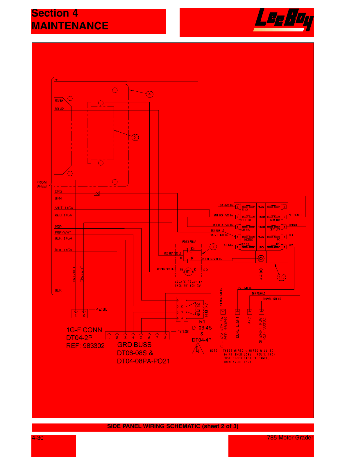
Section 4
MAINTENANCE
4-30
SIDE PANEL WIRING SCHEMATIC (sheet 2 of 3)
785 Motor Grader
Courtesy of Machine.Market
Page 73
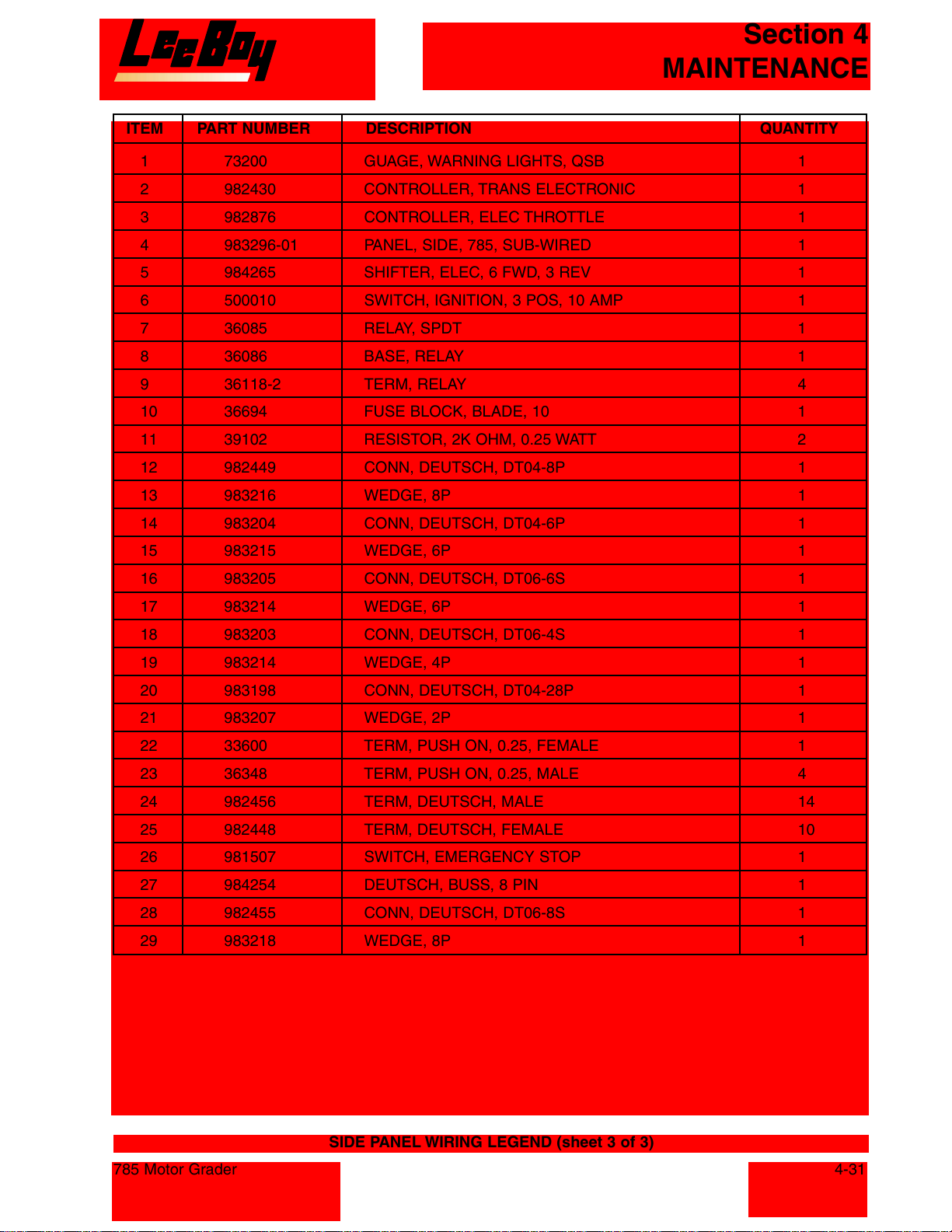
Section 4
MAINTENANCE
ITEM PART NUMBER DESCRIPTION QUANTITY
1 73200 GUAGE, WARNING LIGHTS, QSB 1
2 982430 CONTROLLER, TRANS ELECTRONIC 1
3 982876 CONTROLLER, ELEC THROTTLE 1
4 983296-01 PANEL, SIDE, 785, SUB-WIRED 1
5 984265 SHIFTER, ELEC, 6 FWD, 3 REV 1
6 500010 SWITCH, IGNITION, 3 POS, 10 AMP 1
7 36085 RELAY, SPDT 1
8 36086 BASE, RELAY 1
9 36118-2 TERM, RELAY 4
10 36694 FUSE BLOCK, BLADE, 10 1
11 39102 RESISTOR, 2K OHM, 0.25 WATT 2
12 982449 CONN, DEUTSCH, DT04-8P 1
13 983216 WEDGE, 8P 1
14 983204 CONN, DEUTSCH, DT04-6P 1
15 983215 WEDGE, 6P 1
16 983205 CONN, DEUTSCH, DT06-6S 1
17 983214 WEDGE, 6P 1
18 983203 CONN, DEUTSCH, DT06-4S 1
19 983214 WEDGE, 4P 1
20 983198 CONN, DEUTSCH, DT04-28P 1
21 983207 WEDGE, 2P 1
22 33600 TERM, PUSH ON, 0.25, FEMALE 1
23 36348 TERM, PUSH ON, 0.25, MALE 4
24 982456 TERM, DEUTSCH, MALE 14
25 982448 TERM, DEUTSCH, FEMALE 10
26 981507 SWITCH, EMERGENCY STOP 1
27 984254 DEUTSCH, BUSS, 8 PIN 1
28 982455 CONN, DEUTSCH, DT06-8S 1
29 983218 WEDGE, 8P 1
785 Motor Grader
SIDE PANEL WIRING LEGEND (sheet 3 of 3)
4-31
Courtesy of Machine.Market
Page 74
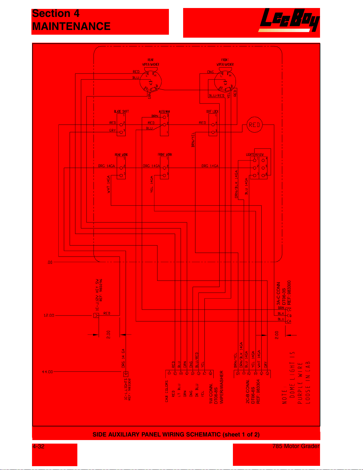
Section 4
MAINTENANCE
4-32
SIDE AUXILIARY PANEL WIRING SCHEMATIC (sheet 1 of 2)
785 Motor Grader
Courtesy of Machine.Market
Page 75
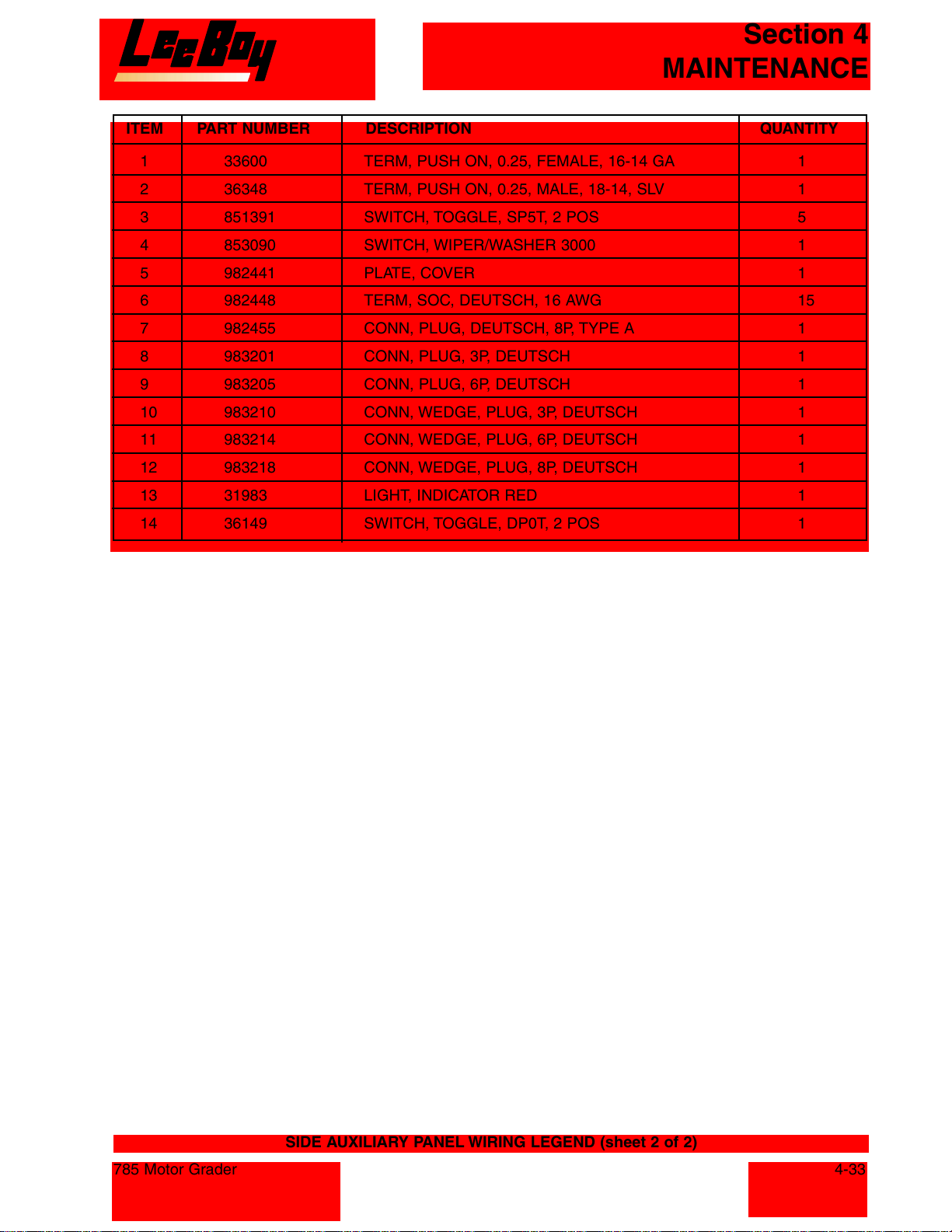
Section 4
MAINTENANCE
ITEM PART NUMBER DESCRIPTION QUANTITY
1 33600 TERM, PUSH ON, 0.25, FEMALE, 16-14 GA 1
2 36348 TERM, PUSH ON, 0.25, MALE, 18-14, SLV 1
3 851391 SWITCH, TOGGLE, SP5T, 2 POS 5
4 853090 SWITCH, WIPER/WASHER 3000 1
5 982441 PLATE, COVER 1
6 982448 TERM, SOC, DEUTSCH, 16 AWG 15
7 982455 CONN, PLUG, DEUTSCH, 8P, TYPE A 1
8 983201 CONN, PLUG, 3P, DEUTSCH 1
9 983205 CONN, PLUG, 6P, DEUTSCH 1
10 983210 CONN, WEDGE, PLUG, 3P, DEUTSCH 1
11 983214 CONN, WEDGE, PLUG, 6P, DEUTSCH 1
12 983218 CONN, WEDGE, PLUG, 8P, DEUTSCH 1
13 31983 LIGHT, INDICATOR RED 1
14 36149 SWITCH, TOGGLE, DP0T, 2 POS 1
785 Motor Grader
SIDE AUXILIARY PANEL WIRING LEGEND (sheet 2 of 2)
4-33
Courtesy of Machine.Market
Page 76
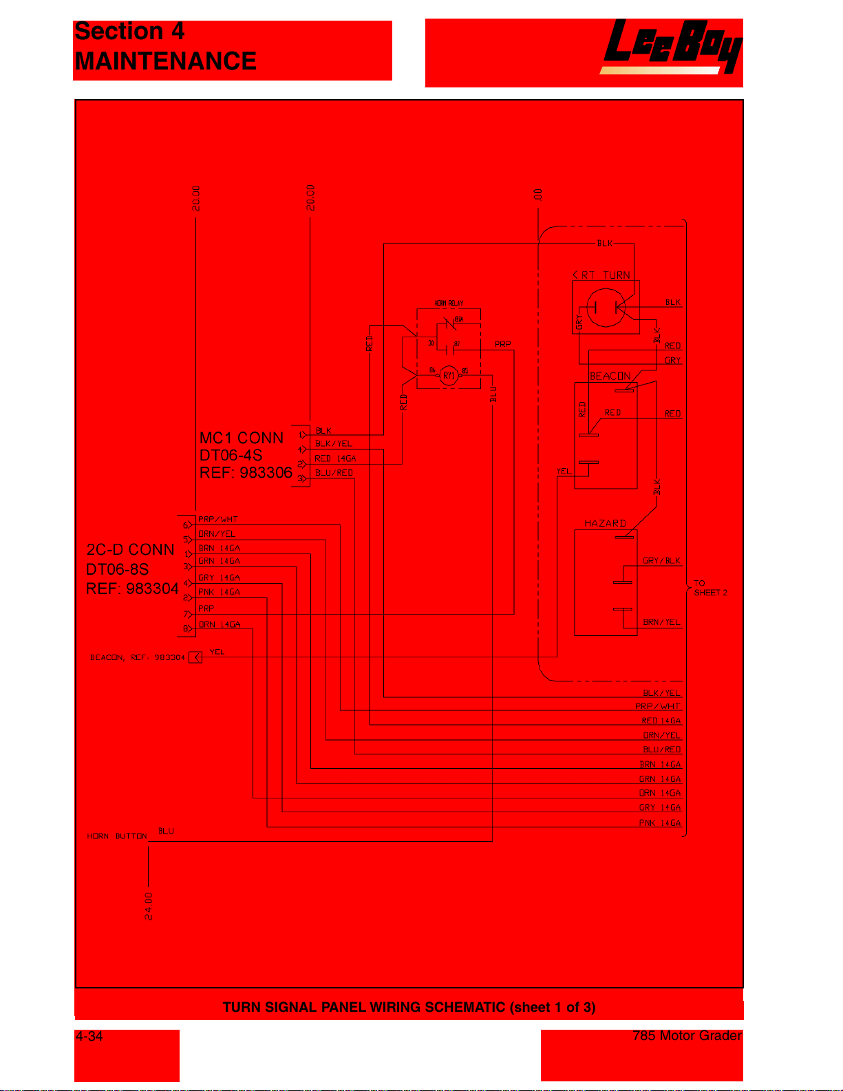
Section 4
MAINTENANCE
4-34
TURN SIGNAL PANEL WIRING SCHEMATIC (sheet 1 of 3)
785 Motor Grader
Courtesy of Machine.Market
Page 77
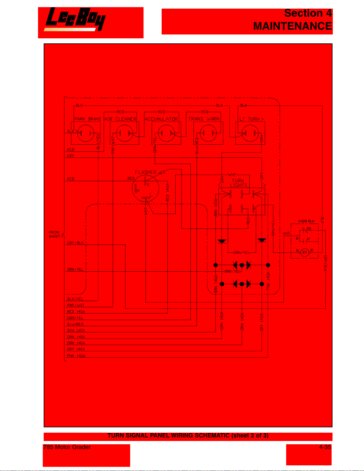
Section 4
MAINTENANCE
785 Motor Grader
TURN SIGNAL PANEL WIRING SCHEMATIC (sheet 2 of 3)
4-35
Courtesy of Machine.Market
Page 78
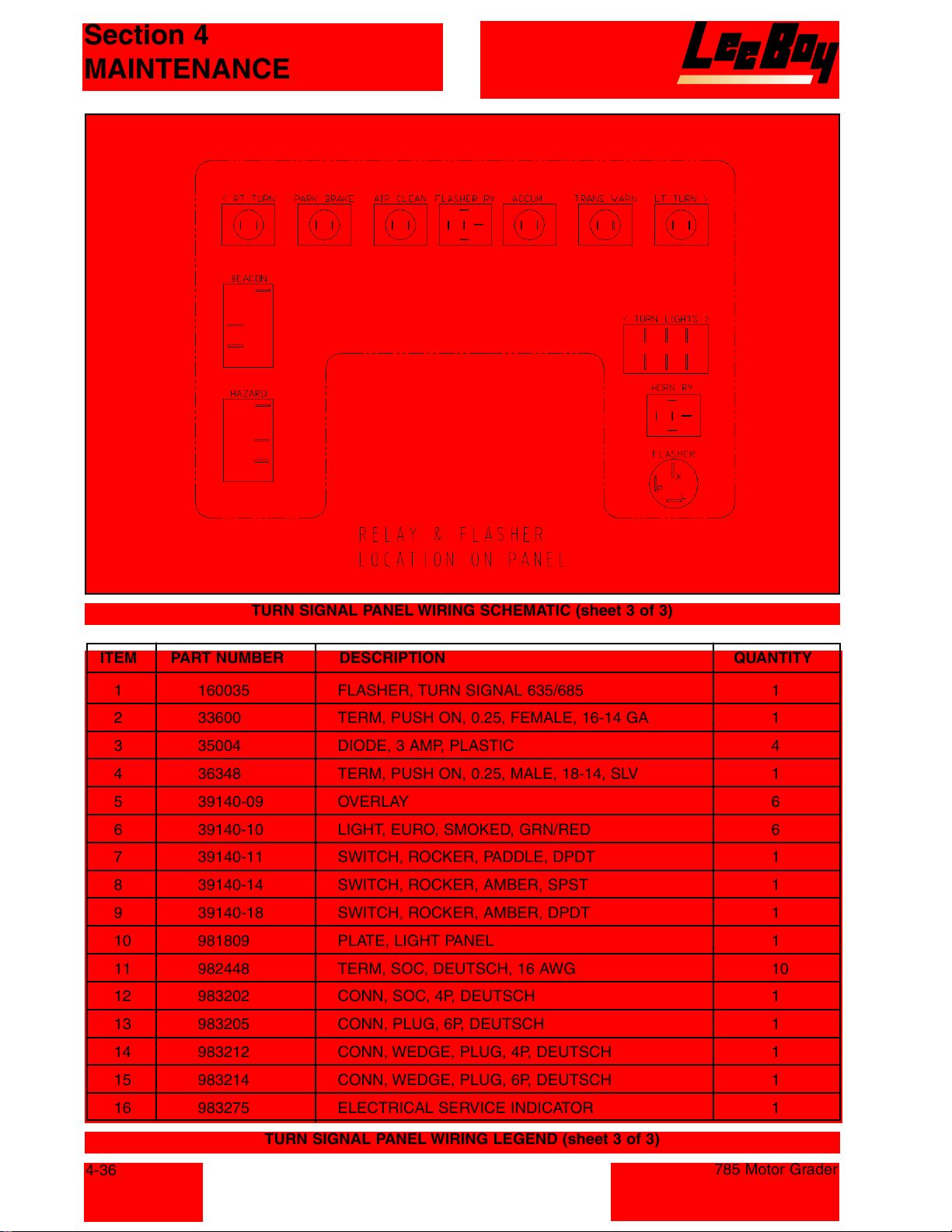
Section 4
MAINTENANCE
TURN SIGNAL PANEL WIRING SCHEMATIC (sheet 3 of 3)
ITEM PART NUMBER DESCRIPTION QUANTITY
1 160035 FLASHER, TURN SIGNAL 635/685 1
2 33600 TERM, PUSH ON, 0.25, FEMALE, 16-14 GA 1
3 35004 DIODE, 3 AMP, PLASTIC 4
4 36348 TERM, PUSH ON, 0.25, MALE, 18-14, SLV 1
5 39140-09 OVERLAY 6
6 39140-10 LIGHT, EURO, SMOKED, GRN/RED 6
7 39140-11 SWITCH, ROCKER, PADDLE, DPDT 1
8 39140-14 SWITCH, ROCKER, AMBER, SPST 1
9 39140-18 SWITCH, ROCKER, AMBER, DPDT 1
10 981809 PLATE, LIGHT PANEL 1
11 982448 TERM, SOC, DEUTSCH, 16 AWG 10
12 983202 CONN, SOC, 4P, DEUTSCH 1
13 983205 CONN, PLUG, 6P, DEUTSCH 1
14 983212 CONN, WEDGE, PLUG, 4P, DEUTSCH 1
15 983214 CONN, WEDGE, PLUG, 6P, DEUTSCH 1
16 983275 ELECTRICAL SERVICE INDICATOR 1
TURN SIGNAL PANEL WIRING LEGEND (sheet 3 of 3)
4-36
785 Motor Grader
Courtesy of Machine.Market
Page 79
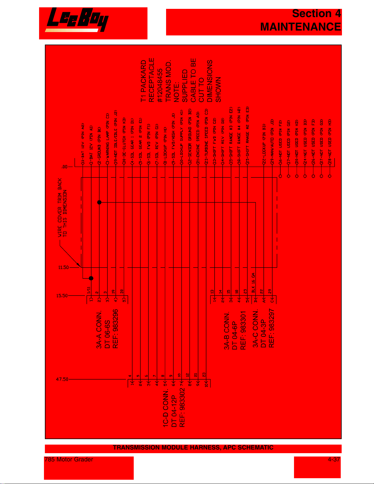
Section 4
MAINTENANCE
785 Motor Grader
TRANSMISSION MODULE HARNESS, APC SCHEMATIC
4-37
Courtesy of Machine.Market
Page 80
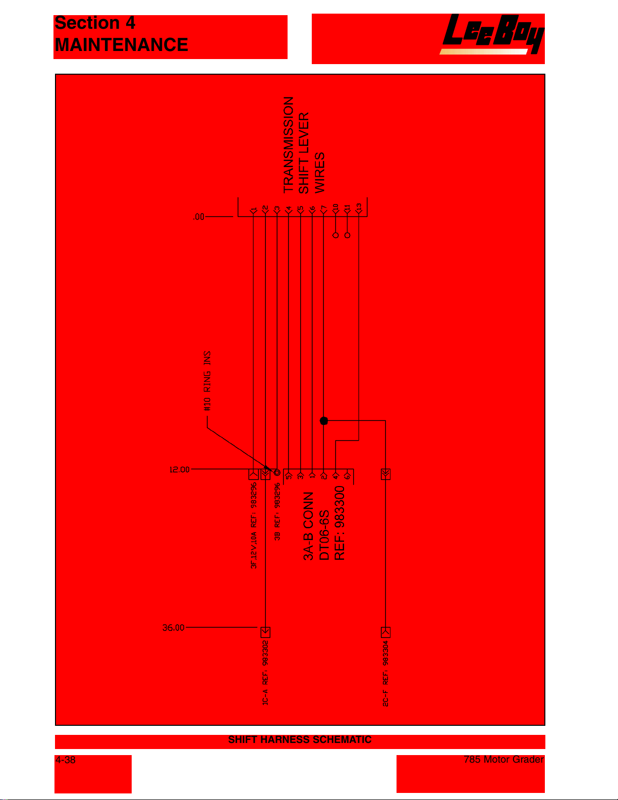
Section 4
MAINTENANCE
4-38
SHIFT HARNESS SCHEMATIC
785 Motor Grader
Courtesy of Machine.Market
Page 81
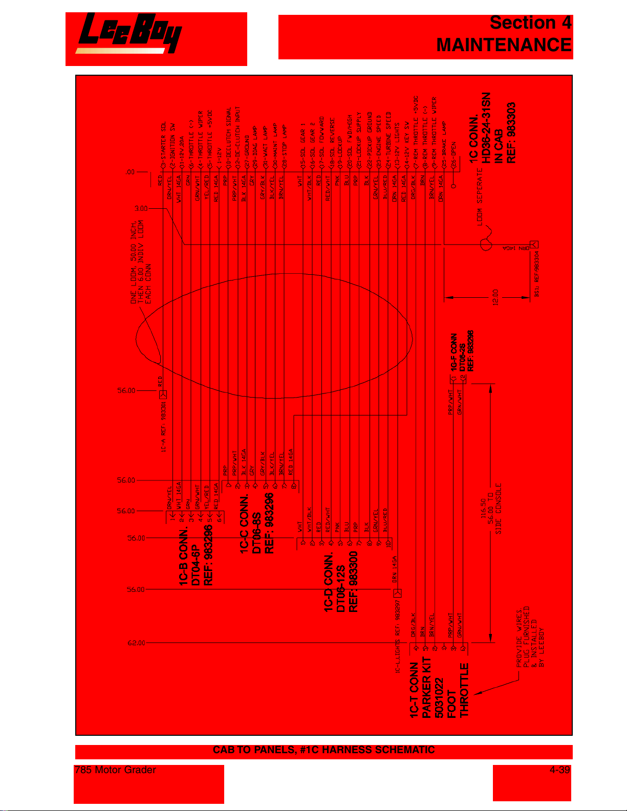
Section 4
MAINTENANCE
785 Motor Grader
CAB TO PANELS, #1C HARNESS SCHEMATIC
4-39
Courtesy of Machine.Market
Page 82
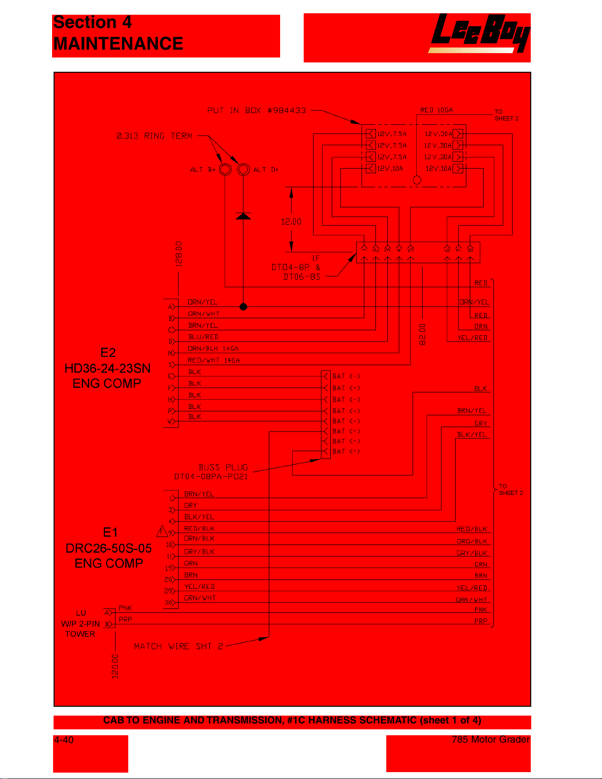
Section 4
MAINTENANCE
4-40
CAB TO ENGINE AND TRANSMISSION, #1C HARNESS SCHEMATIC (sheet 1 of 4)
785 Motor Grader
Courtesy of Machine.Market
Page 83
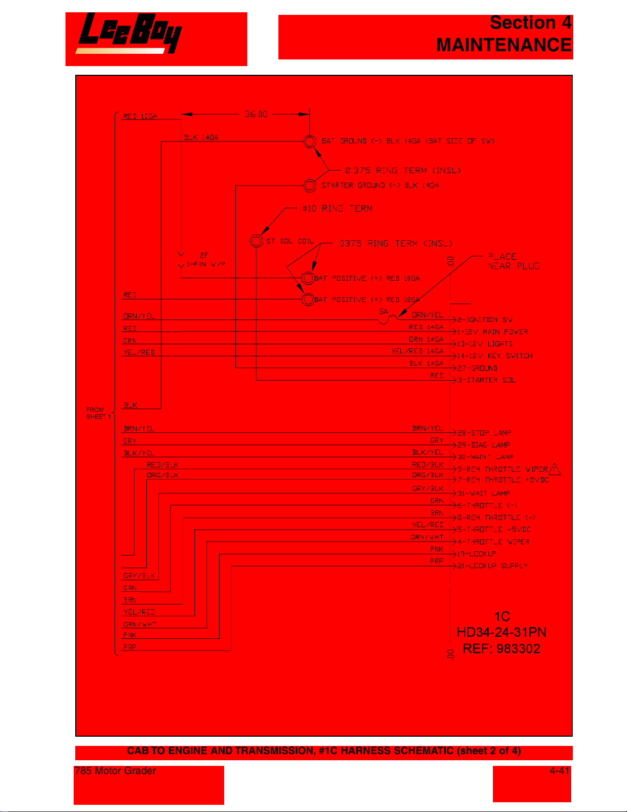
Section 4
MAINTENANCE
CAB TO ENGINE AND TRANSMISSION, #1C HARNESS SCHEMATIC (sheet 2 of 4)
785 Motor Grader
4-41
Courtesy of Machine.Market
Page 84
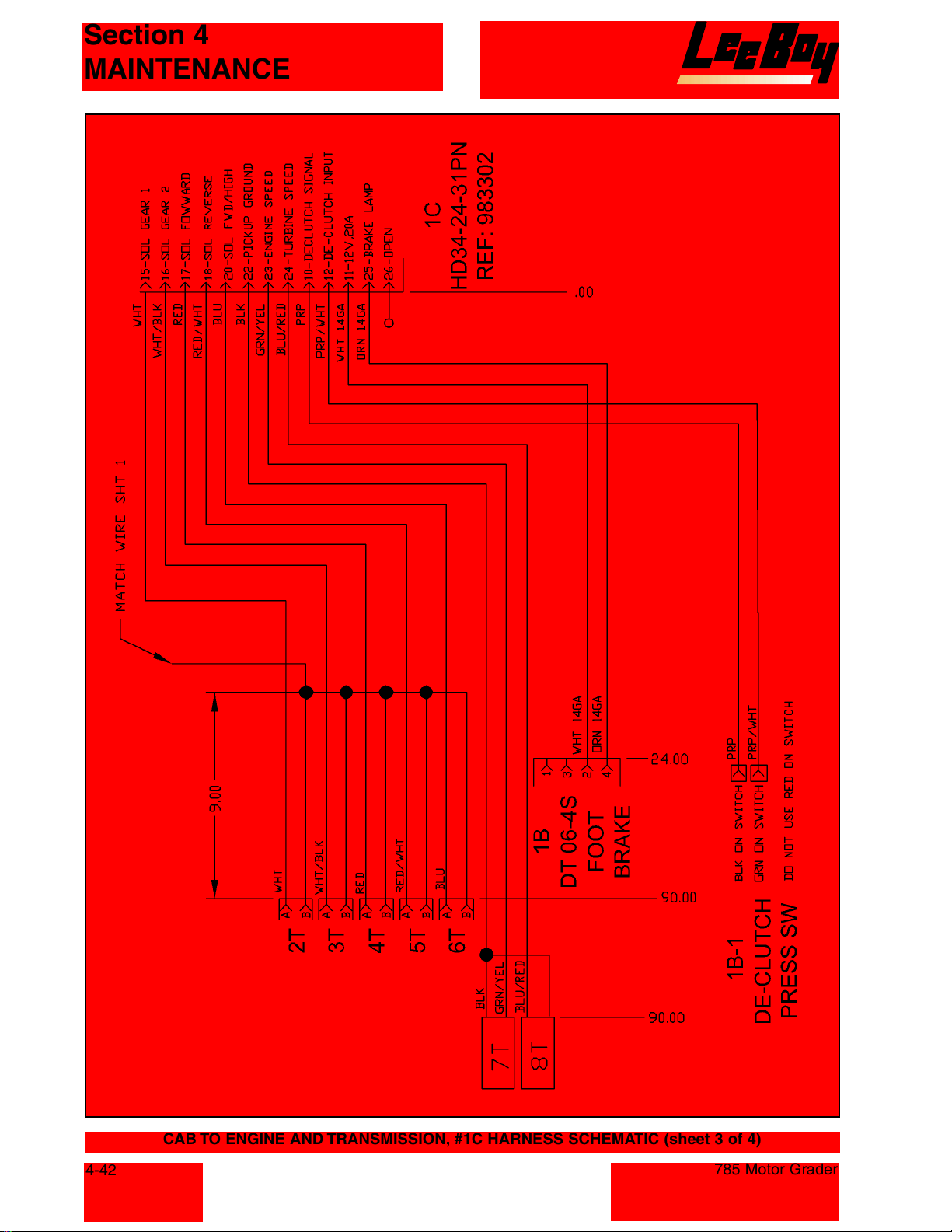
Section 4
MAINTENANCE
4-42
CAB TO ENGINE AND TRANSMISSION, #1C HARNESS SCHEMATIC (sheet 3 of 4)
785 Motor Grader
Courtesy of Machine.Market
Page 85
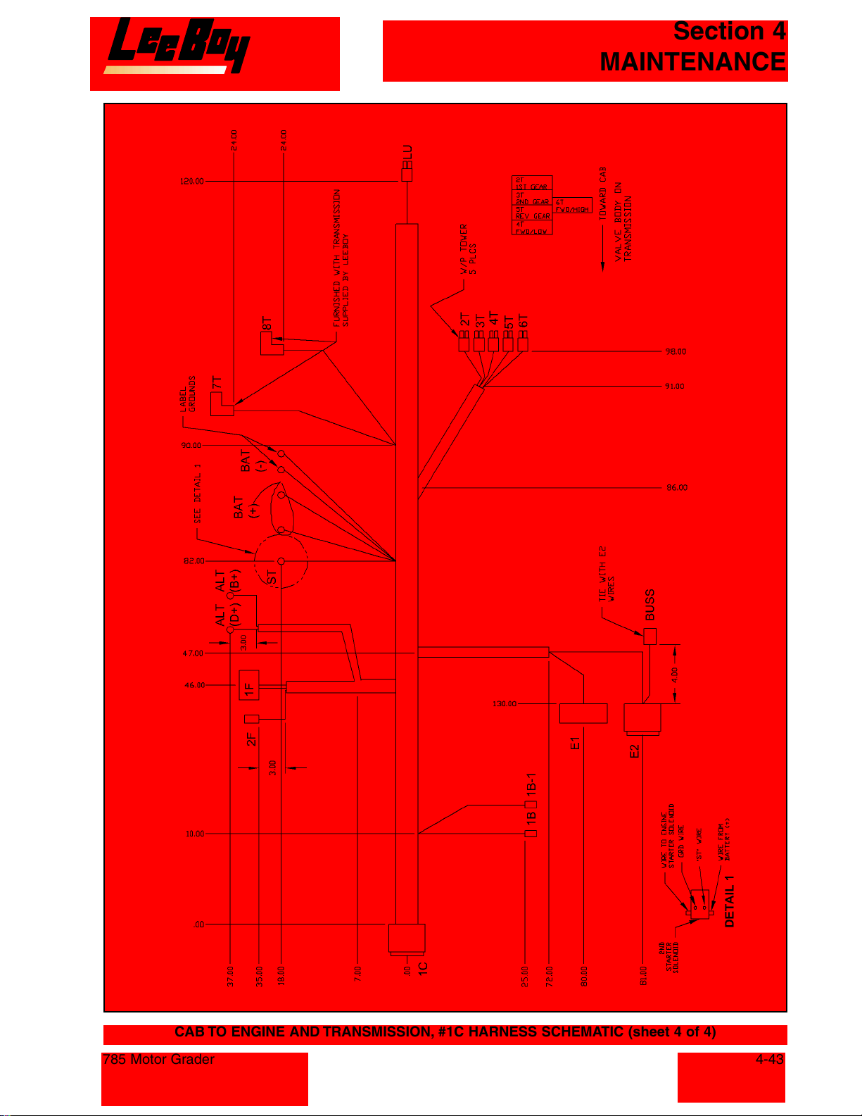
Section 4
MAINTENANCE
CAB TO ENGINE AND TRANSMISSION, #1C HARNESS SCHEMATIC (sheet 4 of 4)
785 Motor Grader
4-43
Courtesy of Machine.Market
Page 86
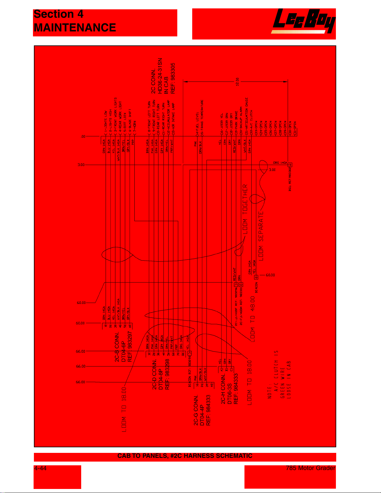
Section 4
MAINTENANCE
4-44
CAB TO PANELS, #2C HARNESS SCHEMATIC
785 Motor Grader
Courtesy of Machine.Market
Page 87
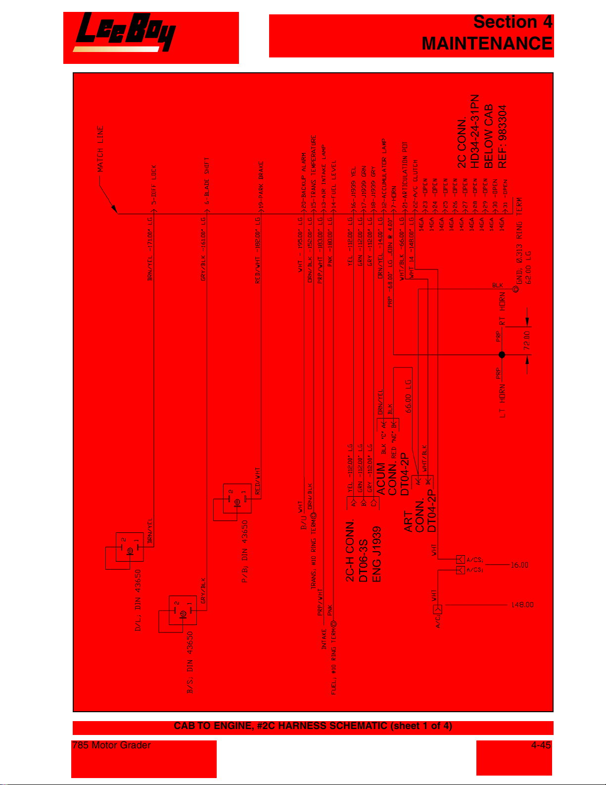
Section 4
MAINTENANCE
785 Motor Grader
CAB TO ENGINE, #2C HARNESS SCHEMATIC (sheet 1 of 4)
4-45
Courtesy of Machine.Market
Page 88
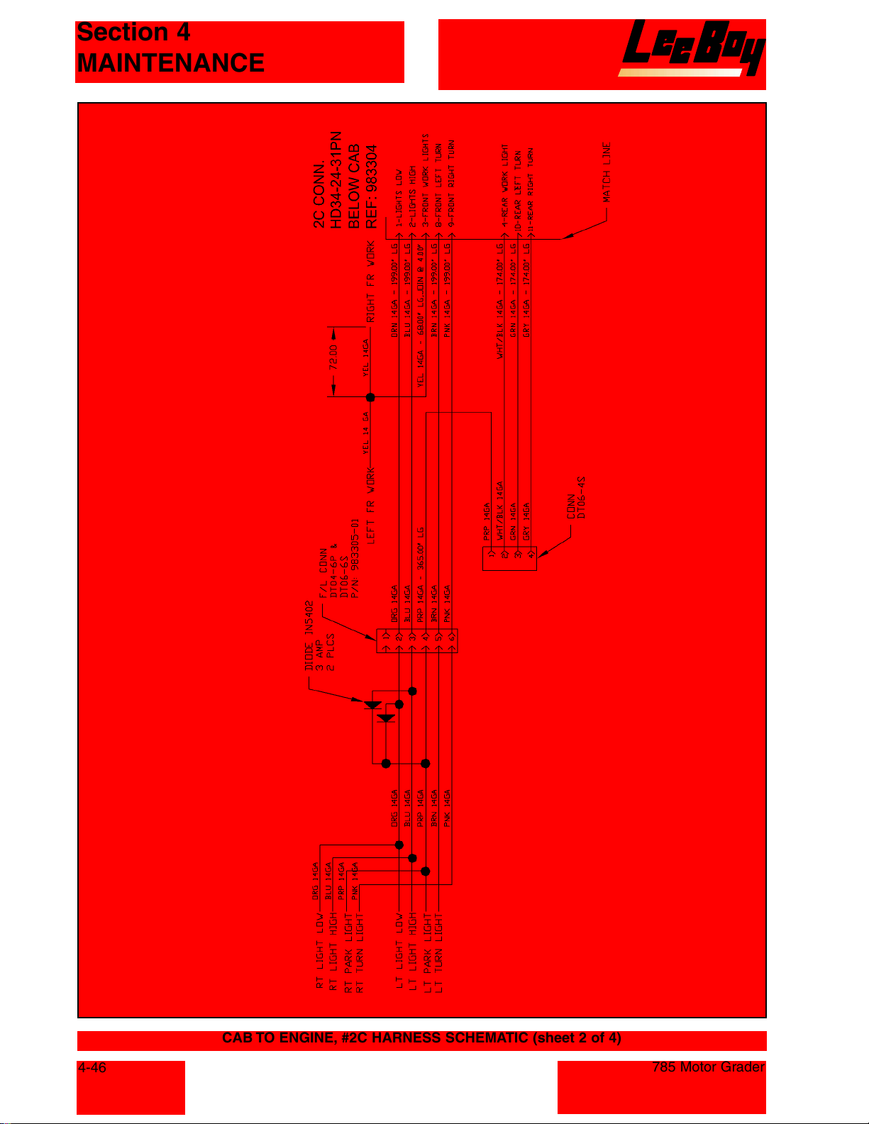
Section 4
MAINTENANCE
4-46
CAB TO ENGINE, #2C HARNESS SCHEMATIC (sheet 2 of 4)
785 Motor Grader
Courtesy of Machine.Market
Page 89
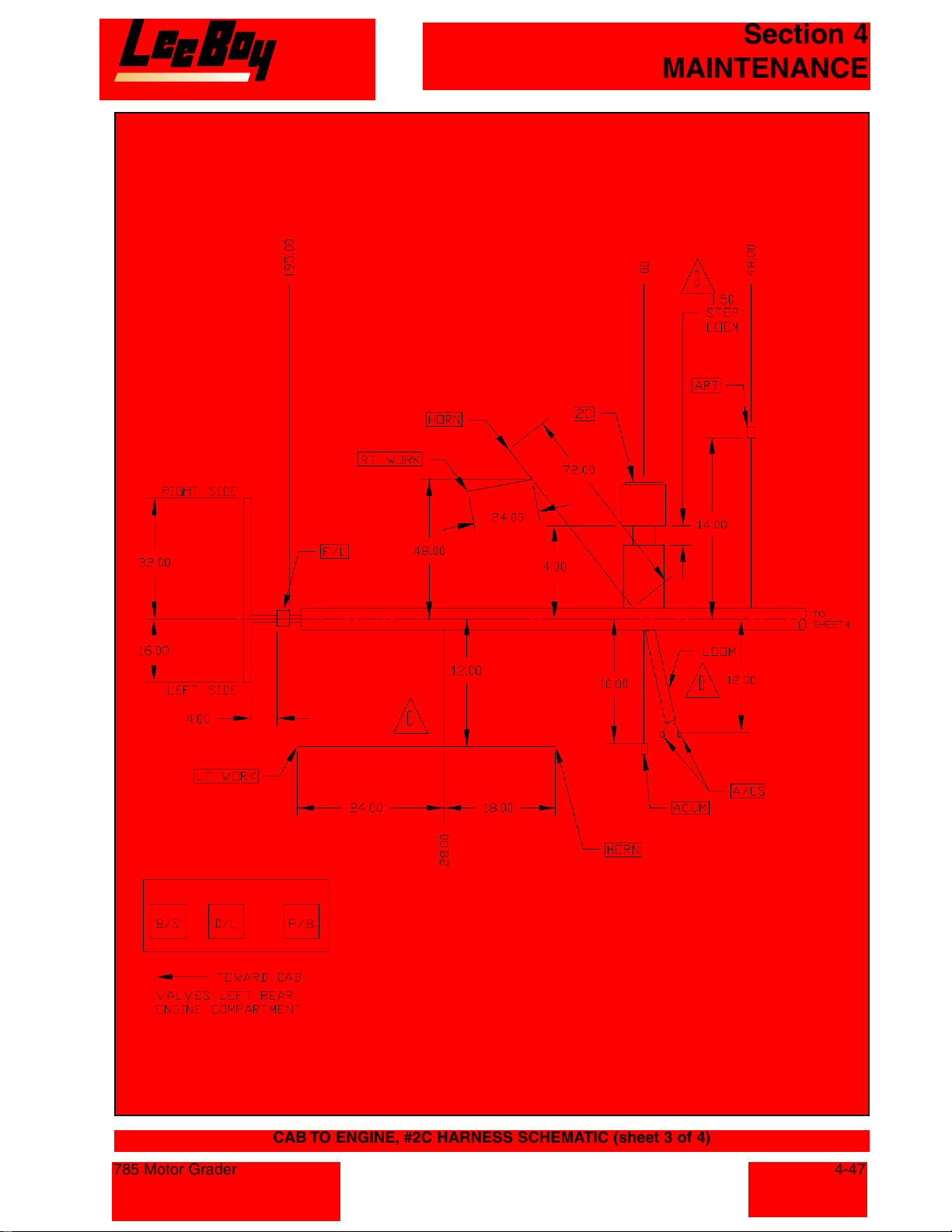
Section 4
MAINTENANCE
785 Motor Grader
CAB TO ENGINE, #2C HARNESS SCHEMATIC (sheet 3 of 4)
4-47
Courtesy of Machine.Market
Page 90
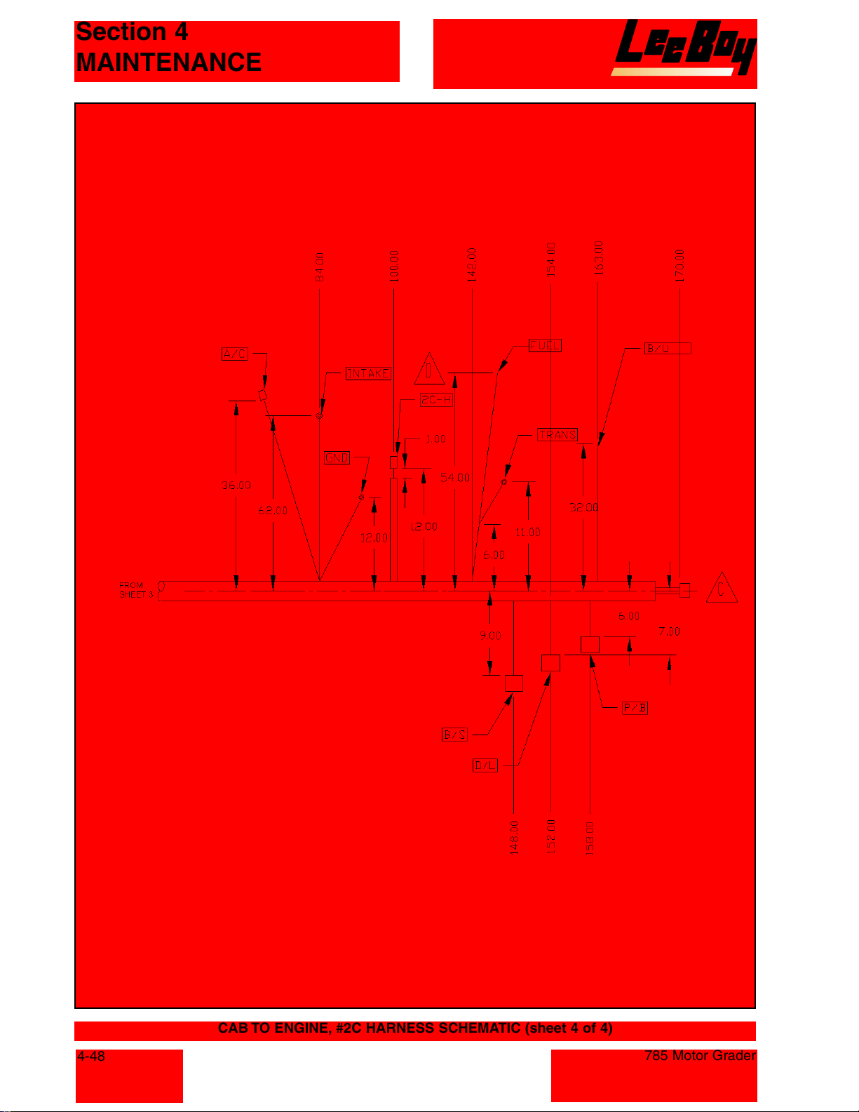
Section 4
MAINTENANCE
4-48
CAB TO ENGINE, #2C HARNESS SCHEMATIC (sheet 4 of 4)
785 Motor Grader
Courtesy of Machine.Market
Page 91
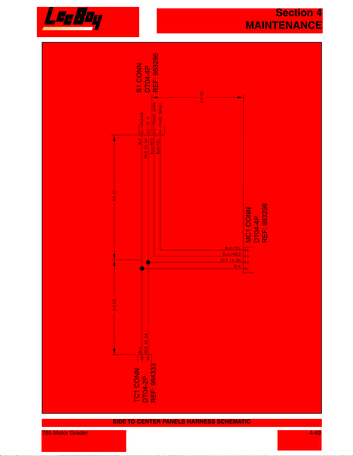
Section 4
MAINTENANCE
785 Motor Grader
SIDE TO CENTER PANELS HARNESS SCHEMATIC
4-49
Courtesy of Machine.Market
Page 92
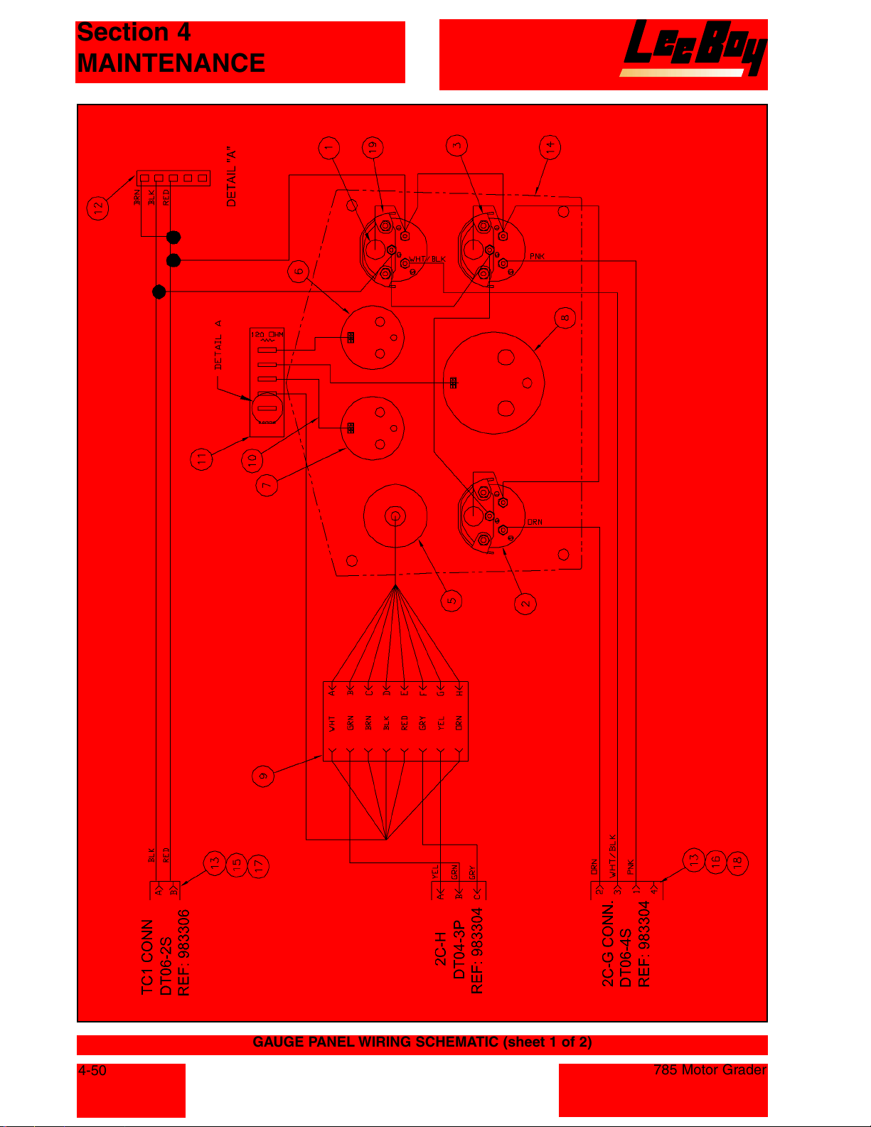
Section 4
MAINTENANCE
4-50
GAUGE PANEL WIRING SCHEMATIC (sheet 1 of 2)
785 Motor Grader
Courtesy of Machine.Market
Page 93
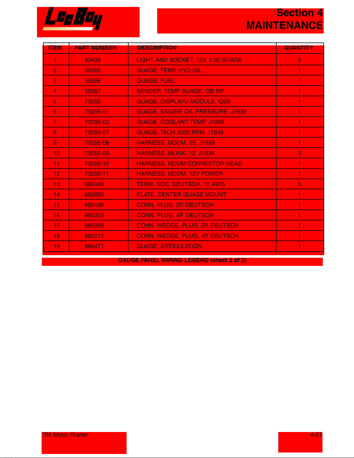
Section 4
MAINTENANCE
ITEM PART NUMBER DESCRIPTION QUANTITY
1 33435 LIGHT AND SOCKET, 12V, 2.00 GUAGE 3
2 35365 GUAGE, TEMP, HYD OIL 1
3 35366 GUAGE, FUEL 1
4 35367 SENDER, TEMP GUAGE, OB MP 1
5 73255 GUAGE, DISPLAYU MODULE, QSB 1
6 73255-01 GUAGE, ENGINE OIL PRESSURE, J1939 1
7 73255-02 GUAGE, COOLANT TEMP, J1939 1
8 73255-07 GUAGE, TACH 3000 RPM, J1939 1
9 73255-08 HARNESS, MDDM, 25, J1939 1
10 73255-09 HARNESS, MLINK, 12, J1939 3
11 73255-10 HARNESS, MDDM CONNECTOR HEAD 1
12 73255-11 HARNESS, MDDM, 12V POWER 1
13 982448 TERM, SOC, DEUTSCH, 16 AWG 5
14 982850 PLATE, CENTER GUAGE MOUNT 1
15 983199 CONN, PLUG, 2P, DEUTSCH 1
16 983203 CONN, PLUG, 4P, DEUTSCH 1
17 983208 CONN, WEDGE, PLUG, 2P, DEUTSCH 1
18 983212 CONN, WEDGE, PLUG, 4P, DEUTSCH 1
19 984471 GUAGE, ARTICULATION 1
GAUGE PANEL WIRING LEGEND (sheet 2 of 2)
785 Motor Grader
4-51
Courtesy of Machine.Market
Page 94
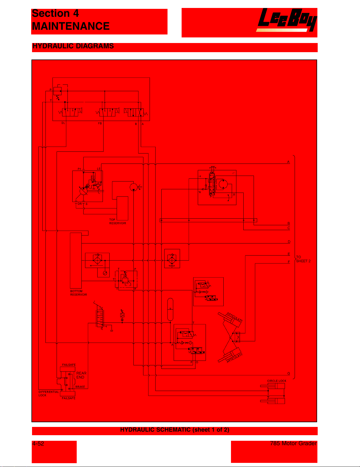
Section 4
MAINTENANCE
HYDRAULIC DIAGRAMS
4-52
HYDRAULIC SCHEMATIC (sheet 1 of 2)
785 Motor Grader
Courtesy of Machine.Market
Page 95
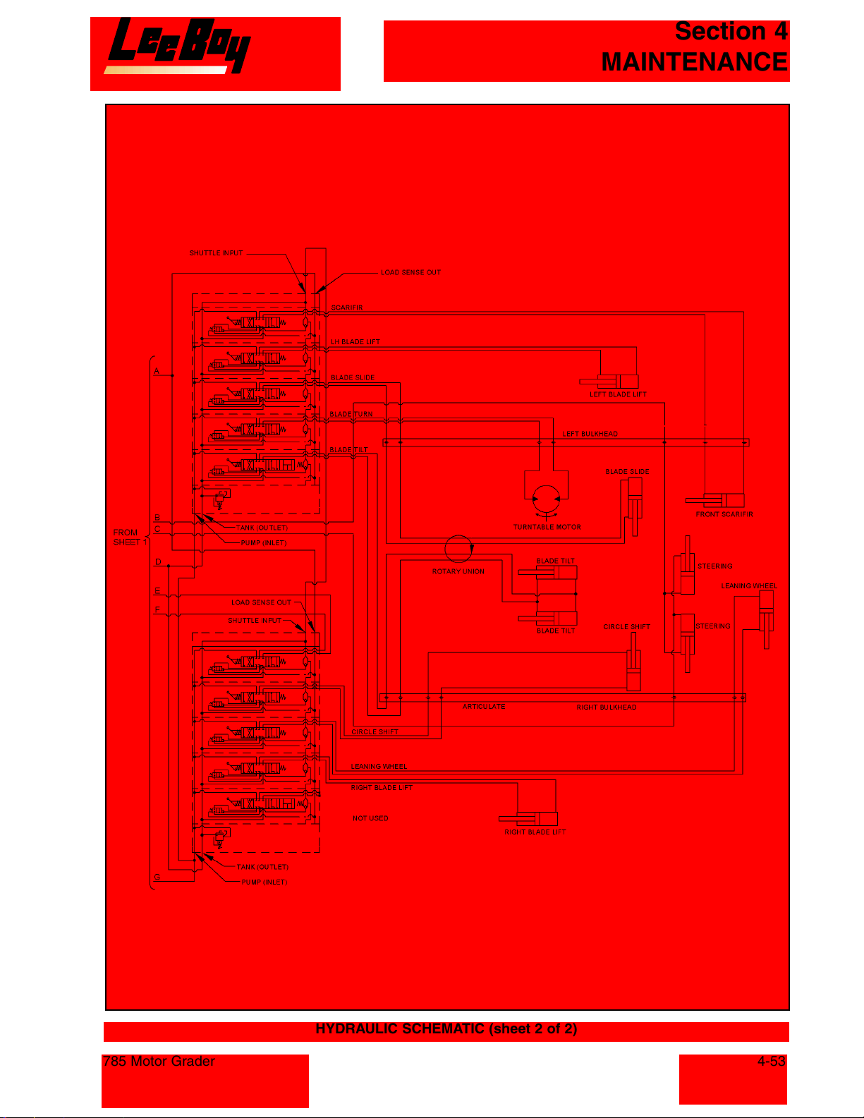
Section 4
MAINTENANCE
785 Motor Grader
HYDRAULIC SCHEMATIC (sheet 2 of 2)
4-53
Courtesy of Machine.Market
Page 96
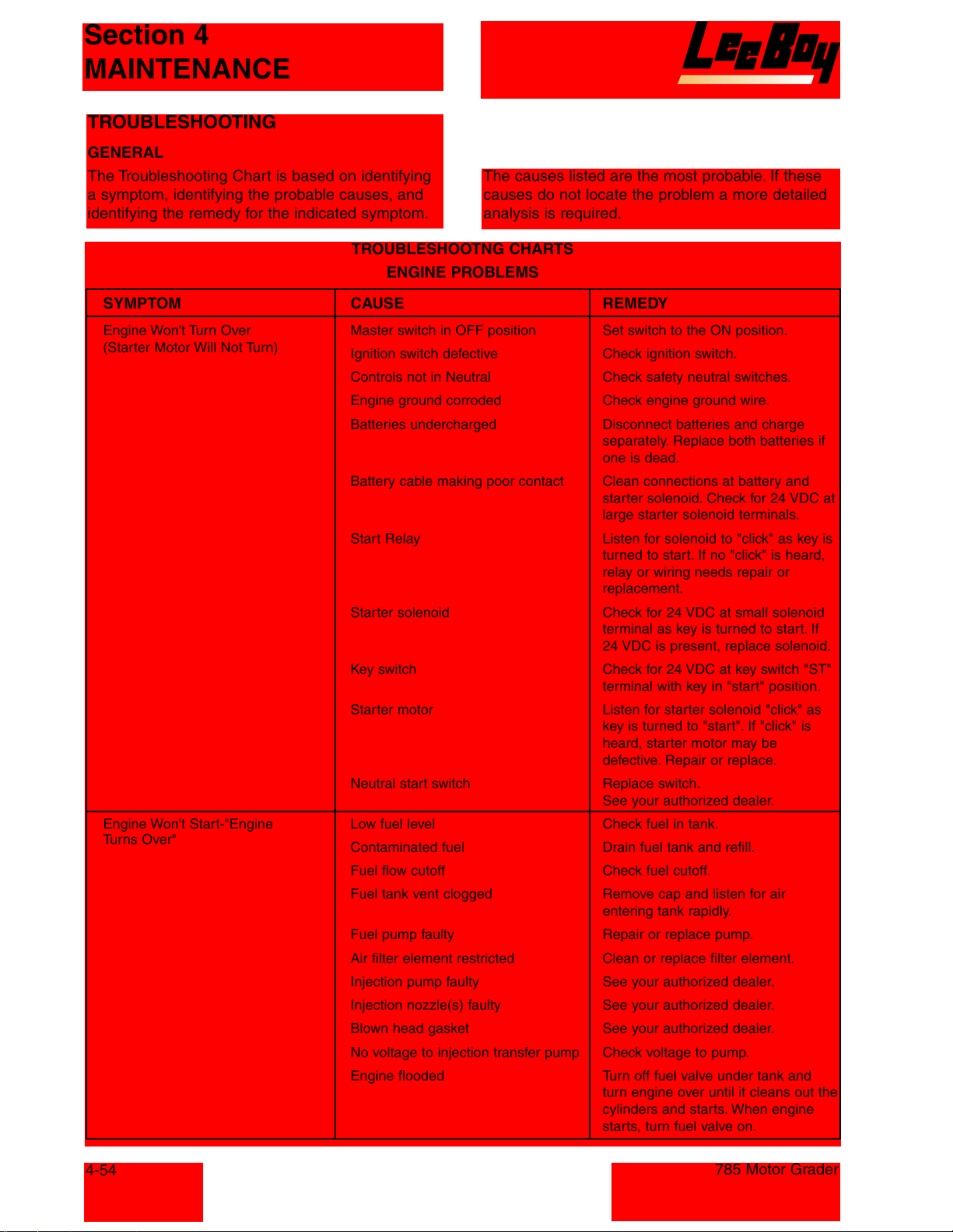
Section 4
MAINTENANCE
TROUBLESHOOTING
GENERAL
The Troubleshooting Chart is based on identifying
a symptom, identifying the probable causes, and
identifying the remedy for the indicated symptom.
TROUBLESHOOTNG CHARTS
ENGINE PROBLEMS
SYMPTOM CAUSE REMEDY
Engine Won't Turn Over Master switch in OFF position Set switch to the ON position.
(Starter Motor Will Not Turn)
Engine Won't Start-"Engine Low fuel level Check fuel in tank.
Turns Over"
Ignition switch defective Check ignition switch.
Controls not in Neutral Check safety neutral switches.
Engine ground corroded Check engine ground wire.
Batteries undercharged Disconnect batteries and charge
Battery cable making poor contact Clean connections at battery and
Start Relay Listen for solenoid to "click" as key is
Starter solenoid Check for 24 VDC at small solenoid
Key switch Check for 24 VDC at key switch "ST"
Starter motor Listen for starter solenoid "click" as
Neutral start switch Replace switch.
Contaminated fuel Drain fuel tank and refill.
Fuel flow cutoff Check fuel cutoff.
Fuel tank vent clogged Remove cap and listen for air
Fuel pump faulty Repair or replace pump.
Air filter element restricted Clean or replace filter element.
Injection pump faulty See your authorized dealer.
Injection nozzle(s) faulty See your authorized dealer.
Blown head gasket See your authorized dealer.
No voltage to injection transfer pump Check voltage to pump.
Engine flooded Turn off fuel valve under tank and
The causes listed are the most probable. If these
causes do not locate the problem a more detailed
analysis is required.
separately. Replace both batteries if
one is dead.
starter solenoid. Check for 24 VDC at
large starter solenoid terminals.
turned to start. If no "click" is heard,
relay or wiring needs repair or
replacement.
terminal as key is turned to start. If
24 VDC is present, replace solenoid.
terminal with key in "start" position.
key is turned to "start". If "click" is
heard, starter motor may be
defective. Repair or replace.
See your authorized dealer.
entering tank rapidly.
turn engine over until it cleans out the
cylinders and starts. When engine
starts, turn fuel valve on.
4-54
785 Motor Grader
Courtesy of Machine.Market
Page 97
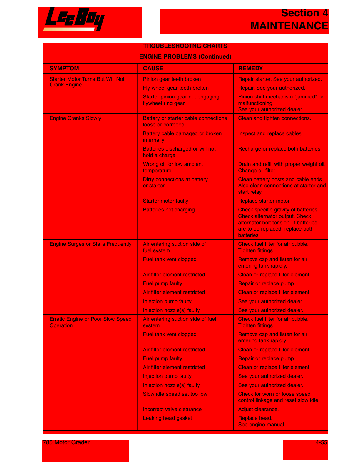
Section 4
MAINTENANCE
TROUBLESHOOTNG CHARTS
ENGINE PROBLEMS (Continued)
SYMPTOM CAUSE REMEDY
Starter Motor Turns But Will Not Pinion gear teeth broken Repair starter. See your authorized.
Crank Engine
Engine Cranks Slowly Battery or starter cable connections Clean and tighten connections.
Engine Surges or Stalls Frequently Air entering suction side of Check fuel filter for air bubble.
Erratic Engine or Poor Slow Speed Air entering suction side of fuel Check fuel filter for air bubble.
Operation system Tighten fittings.
Fly wheel gear teeth broken Repair. See your authorized.
Starter pinion gear not engaging Pinion shift mechanism "jammed" or
flywheel ring gear malfunctioning.
See your authorized dealer.
loose or corroded
Battery cable damaged or broken Inspect and replace cables.
internally
Batteries discharged or will not Recharge or replace both batteries.
hold a charge
Wrong oil for low ambient Drain and refill with proper weight oil.
temperature Change oil filter.
Dirty connections at battery Clean battery posts and cable ends.
or starter Also clean connections at starter and
start relay.
Starter motor faulty Replace starter motor.
Batteries not charging Check specific gravity of batteries.
Check alternator output. Check
alternator belt tension. If batteries
are to be replaced, replace both
batteries.
fuel system Tighten fittings.
Fuel tank vent clogged Remove cap and listen for air
entering tank rapidly.
Air filter element restricted Clean or replace filter element.
Fuel pump faulty Repair or replace pump.
Air filter element restricted Clean or replace filter element.
Injection pump faulty See your authorized dealer.
Injection nozzle(s) faulty See your authorized dealer.
Fuel tank vent clogged Remove cap and listen for air
entering tank rapidly.
Air filter element restricted Clean or replace filter element.
Fuel pump faulty Repair or replace pump.
Air filter element restricted Clean or replace filter element.
Injection pump faulty See your authorized dealer.
Injection nozzle(s) faulty See your authorized dealer.
Slow idle speed set too low Check for worn or loose speed
control linkage and reset slow idle.
Incorrect valve clearance Adjust clearance.
Leaking head gasket Replace head.
See engine manual.
785 Motor Grader
4-55
Courtesy of Machine.Market
Page 98
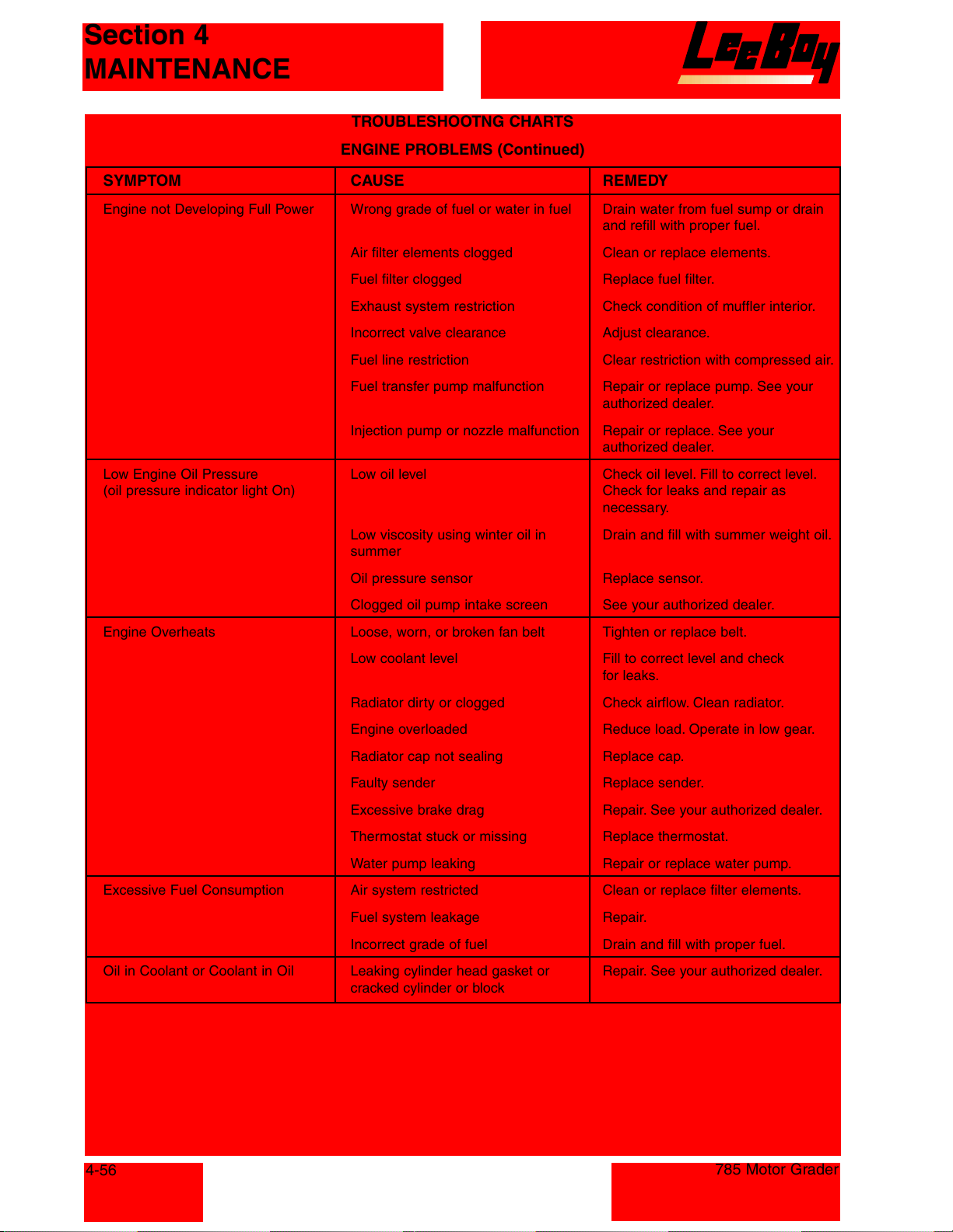
Section 4
MAINTENANCE
TROUBLESHOOTNG CHARTS
ENGINE PROBLEMS (Continued)
SYMPTOM CAUSE REMEDY
Engine not Developing Full Power Wrong grade of fuel or water in fuel Drain water from fuel sump or drain
and refill with proper fuel.
Air filter elements clogged Clean or replace elements.
Fuel filter clogged Replace fuel filter.
Exhaust system restriction Check condition of muffler interior.
Incorrect valve clearance Adjust clearance.
Fuel line restriction Clear restriction with compressed air.
Fuel transfer pump malfunction Repair or replace pump. See your
authorized dealer.
Injection pump or nozzle malfunction Repair or replace. See your
authorized dealer.
Low Engine Oil Pressure Low oil level Check oil level. Fill to correct level.
(oil pressure indicator light On) Check for leaks and repair as
necessary.
Low viscosity using winter oil in Drain and fill with summer weight oil.
summer
Oil pressure sensor Replace sensor.
Clogged oil pump intake screen See your authorized dealer.
Engine Overheats Loose, worn, or broken fan belt Tighten or replace belt.
Low coolant level Fill to correct level and check
for leaks.
Radiator dirty or clogged Check airflow. Clean radiator.
Engine overloaded Reduce load. Operate in low gear.
Radiator cap not sealing Replace cap.
Faulty sender Replace sender.
Excessive brake drag Repair. See your authorized dealer.
Thermostat stuck or missing Replace thermostat.
Water pump leaking Repair or replace water pump.
Excessive Fuel Consumption Air system restricted Clean or replace filter elements.
Fuel system leakage Repair.
Incorrect grade of fuel Drain and fill with proper fuel.
Oil in Coolant or Coolant in Oil Leaking cylinder head gasket or Repair. See your authorized dealer.
cracked cylinder or block
4-56
785 Motor Grader
Courtesy of Machine.Market
Page 99
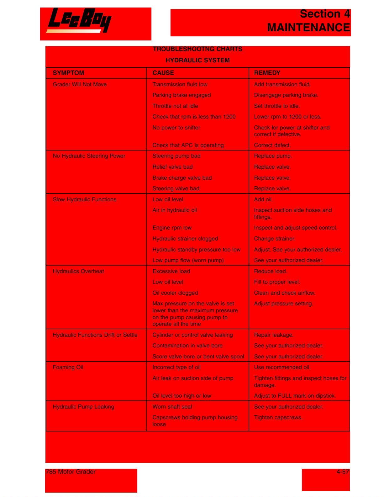
Section 4
MAINTENANCE
TROUBLESHOOTNG CHARTS
HYDRAULIC SYSTEM
SYMPTOM CAUSE REMEDY
Grader Will Not Move Transmission fluid low Add transmission fluid.
Parking brake engaged Disengage parking brake.
Throttle not at idle Set throttle to idle.
Check that rpm is less than 1200 Lower rpm to 1200 or less.
No power to shifter Check for power at shifter and
correct if defective.
Check that APC is operating Correct defect.
No Hydraulic Steering Power Steering pump bad Replace pump.
Relief valve bad Replace valve.
Brake charge valve bad Replace valve.
Steering valve bad Replace valve.
Slow Hydraulic Functions Low oil level Add oil.
Air in hydraulic oil Inspect suction side hoses and
fittings.
Engine rpm low Inspect and adjust speed control.
Hydraulic strainer clogged Change strainer.
Hydraulic standby pressure too low Adjust. See your authorized dealer.
Low pump flow (worn pump) See your authorized dealer.
Hydraulics Overheat Excessive load Reduce load.
Low oil level Fill to proper level.
Oil cooler clogged Clean and check airflow.
Max pressure on the valve is set Adjust pressure setting.
lower than the maximum pressure
on the pump causing pump to
operate all the time
Hydraulic Functions Drift or Settle Cylinder or control valve leaking Repair leakage.
Contamination in valve bore See your authorized dealer.
Score valve bore or bent valve spool See your authorized dealer.
Foaming Oil Incorrect type of oil Use recommended oil.
Air leak on suction side of pump Tighten fittings and inspect hoses for
damage.
Oil level too high or low Adjust to FULL mark on dipstick.
Hydraulic Pump Leaking Worn shaft seal See your authorized dealer.
Capscrews holding pump housing Tighten capscrews.
loose
785 Motor Grader
Courtesy of Machine.Market
4-57
Page 100
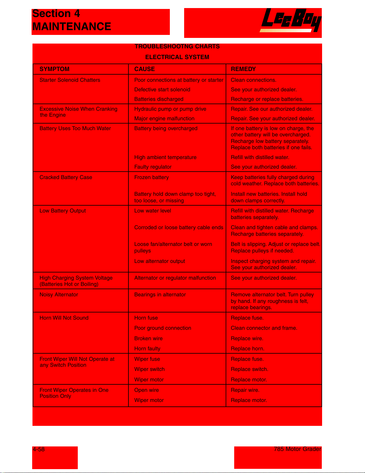
Section 4
MAINTENANCE
TROUBLESHOOTNG CHARTS
ELECTRICAL SYSTEM
SYMPTOM CAUSE REMEDY
Starter Solenoid Chatters Poor connections at battery or starter Clean connections.
Defective start solenoid See your authorized dealer.
Batteries discharged Recharge or replace batteries.
Excessive Noise When Cranking Hydraulic pump or pump drive Repair. See our authorized dealer.
the Engine
Battery Uses Too Much Water Battery being overcharged If one battery is low on charge, the
Cracked Battery Case Frozen battery Keep batteries fully charged during
Major engine malfunction Repair. See your authorized dealer.
other battery will be overcharged.
Recharge low battery separately.
Replace both batteries if one fails.
High ambient temperature Refill with distilled water.
Faulty regulator See your authorized dealer.
cold weather. Replace both batteries.
Battery hold down clamp too tight, Install new batteries. Install hold
too loose, or missing down clamps correctly.
Low Battery Output Low water level Refill with distilled water. Recharge
batteries separately.
Corroded or loose battery cable ends Clean and tighten cable and clamps.
Recharge batteries separately.
Loose fan/alternator belt or worn Belt is slipping. Adjust or replace belt.
pulleys Replace pulleys if needed.
Low alternator output Inspect charging system and repair.
See your authorized dealer.
High Charging System Voltage Alternator or regulator malfunction See your authorized dealer.
(Batteries Hot or Boiling)
Noisy Alternator Bearings in alternator Remove alternator belt. Turn pulley
by hand. If any roughness is felt,
replace bearings.
Horn Will Not Sound Horn fuse Replace fuse.
Poor ground connection Clean connector and frame.
Broken wire Replace wire.
Horn faulty Replace horn.
Front Wiper Will Not Operate at Wiper fuse Replace fuse.
any Switch Position
Wiper switch Replace switch.
Wiper motor Replace motor.
Front Wiper Operates in One Open wire Repair wire.
Position Only
Wiper motor Replace motor.
4-58
785 Motor Grader
Courtesy of Machine.Market
 Loading...